Si deseas distinguir tus productos, servicios o ambos de los de otra empresa, es posible que necesites una marca o nombre comercial. Descubre qué son, en qué consiste su procedimiento de registro y qué implica.

Información sobre los plazos de presentación de solicitudes de transformación de marcas de la Unión Europea en marca nacional española. Más información


Si tienes un nuevo dispositivo, producto o procedimiento que resuelva un problema técnico o tenga una ventaja práctica, existen distintas formas de protegerlo en España y en otros países. Descubre cómo hacerlo.

¿Tu innovación reside en la estética, la ornamentación o la apariencia de tu producto? Protégela mediante un diseño industrial. Descubre qué derechos confiere el registro y cómo realizar la tramitación.

Las indicaciones geográficas protegen el nombre de un producto originario de una zona geográfica, a la cual le debe una determinada calidad, reputación u otra característica. Descubre qué son, en qué consiste su procedimiento de registro y qué beneficios conceden.

Las patentes publicadas en todo el mundo son una valiosa fuente de información científica, técnica y comercial.

Si eres emprendedor/a o una empresa y quieres potenciar y mejorar la rentabilidad de tu negocio protegiendo de forma adecuada los activos intangibles de tu organización, en este espacio encontrarás lo necesario.


 392
resultados
392
resultados
 Última actualización
22/09/2026 [07:03:00]
Última actualización
22/09/2026 [07:03:00]


 Resultados 275 a 300 de 392

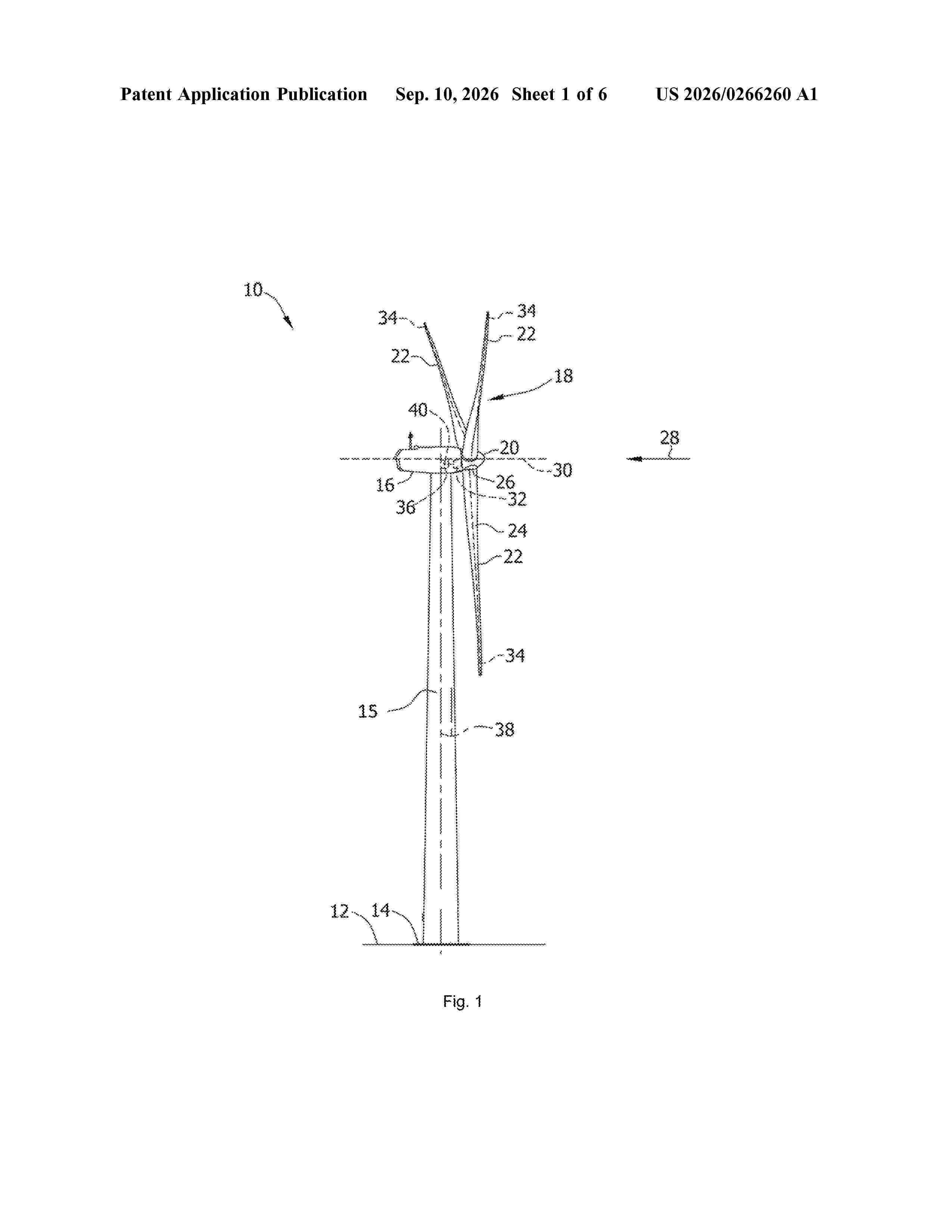
Resumen de: US20260266260A1
The present disclosure is related to methods for determining a thrust limit for a wind turbine and methods for operating a wind turbine. The methods comprise determining an operational state of a blade load monitoring system of the wind turbine. Additionally, the methods comprise adjusting a thrust threshold of the wind turbine at least partially based on the operational state of the blade monitoring system. Further, the methods also comprise operating the wind turbine such that a thrust load on a rotor of the wind turbine is maintained at or below the adjusted thrust threshold. A control system suitable to maintain thrust loads at or below a thrust threshold is also provided, as well as wind turbines including such a control system.

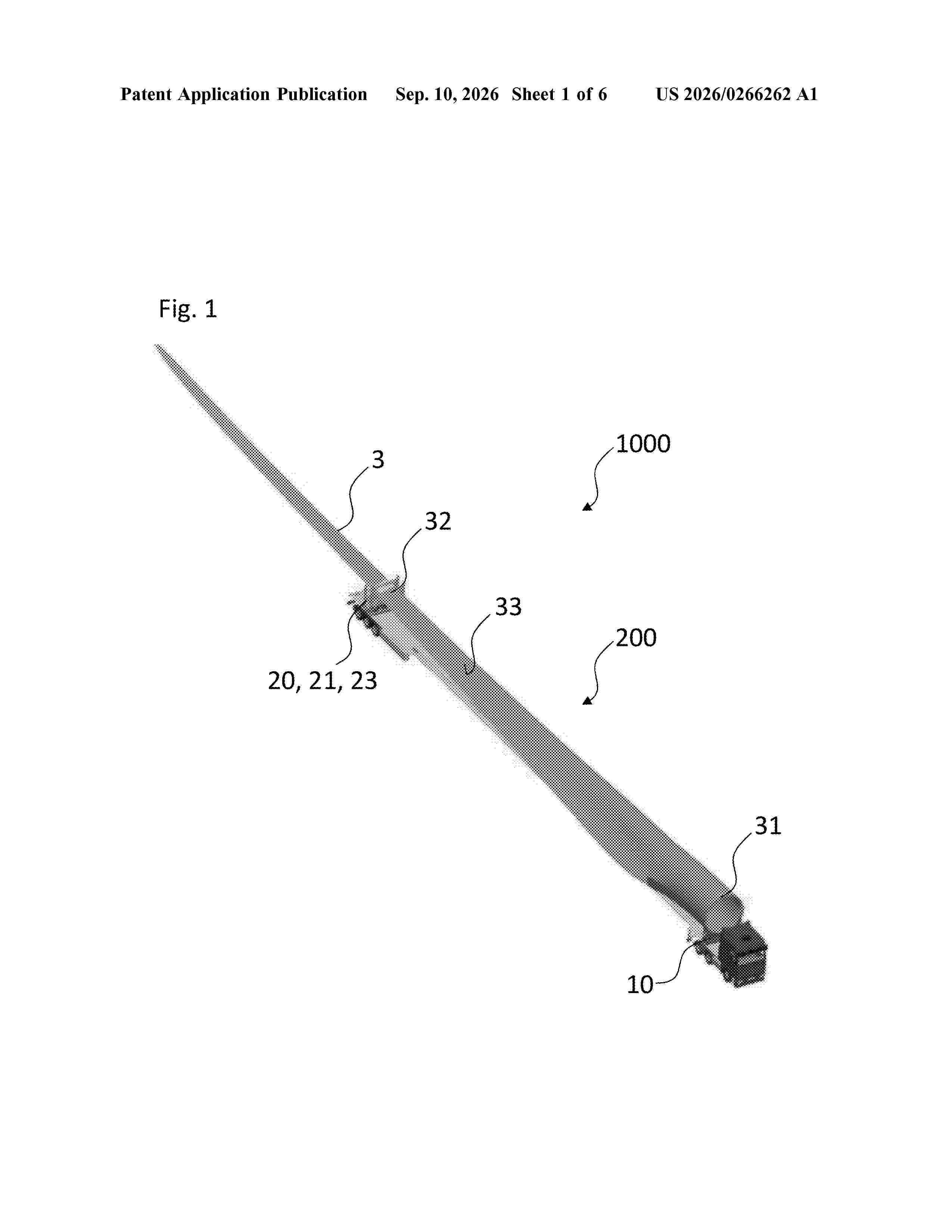
Resumen de: US20260266262A1
According to an embodiment, the transport system includes a root support element which is configured to be connected to the root end of a rotor blade. Furthermore, the transport system includes a clamping element which is configured to clamp a section of the rotor blade distant from the root end. The transport system enables the transport of a rotor blade for a wind turbine with the pressure side of the rotor blade up when the root end of the rotor blade is connected to the root support element and when the section of the rotor blade is clamped in the clamping element.
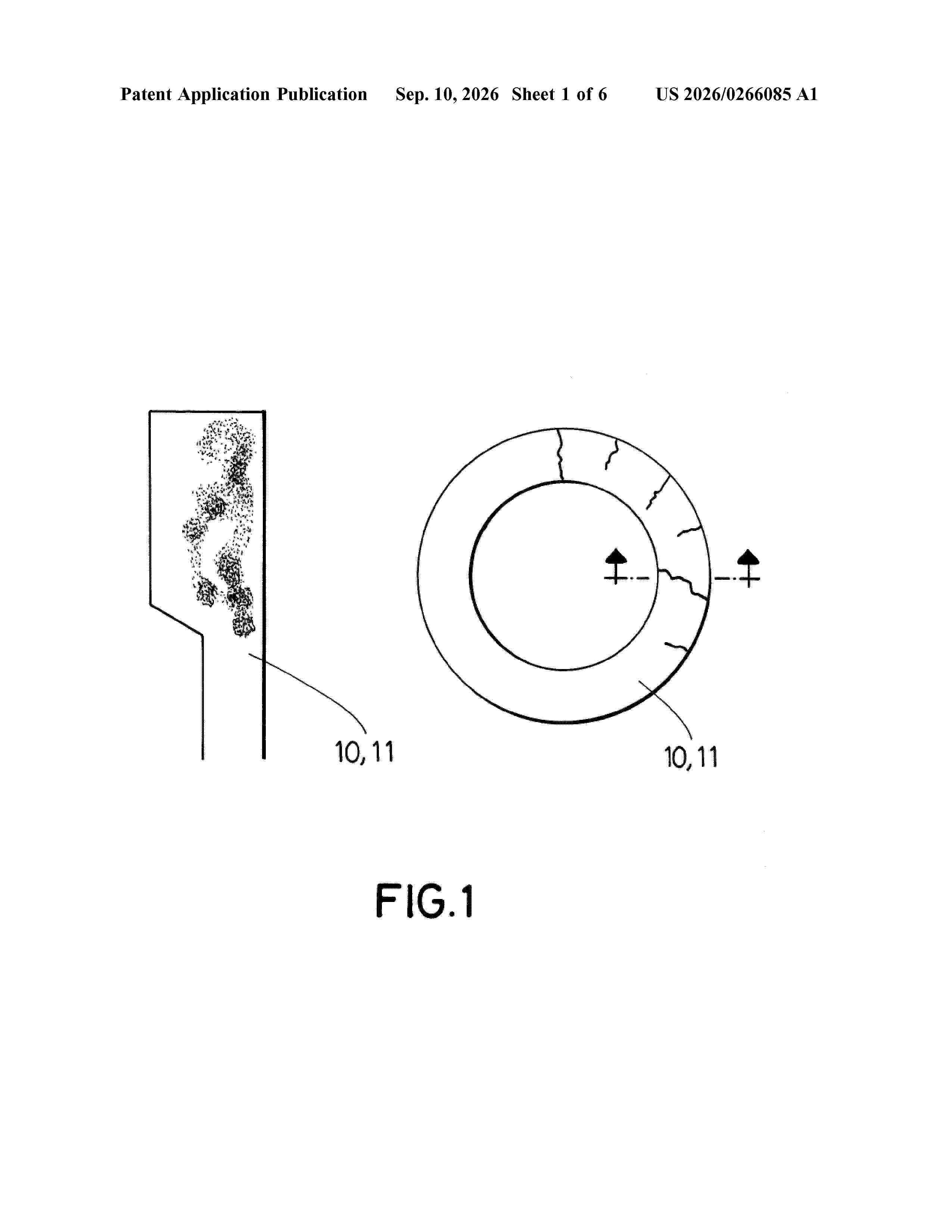
Resumen de: US20260266085A1
The present invention relates to a reinforcement system for a tower (1) of a wind turbine that avoids the appearance or propagation of cracks or openings in the surface of a concrete element of the tower of the wind turbine once the tower is subjected to post-tensioning forces, exerting a radial compression force to the concrete element, wherein the invention also relates to a tower (1) of a wind turbine comprising at least one reinforcement system (2,3) and to a method of reinforcing a tower of a wind turbine.
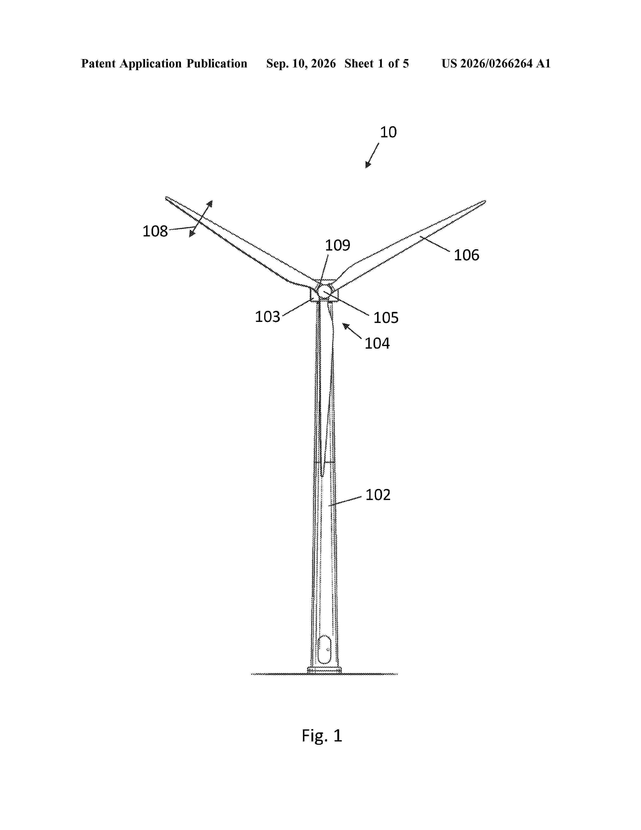
Resumen de: US20260266264A1
The invention estimates a velocity of a top of a tower of a wind turbine that has a rotor and a plurality of rotor blades. The invention involves obtaining a measured acceleration indicative of tower top acceleration in the fore-aft direction. The invention involves obtaining an estimated thrust force experienced by the rotor, and providing this estimate as input to a defined observer model describing motion of the tower top. The invention involves determining an error based on a difference between the measured acceleration and an estimated acceleration obtained using the observer model, and providing the error as input to the observer model as part of a feedback loop. The invention involves estimating, using the observer model, velocity of the tower top in the fore-aft direction. The estimated thrust force is obtained based on measured flap loading on the rotor blades.
Resumen de: US20260266267A1
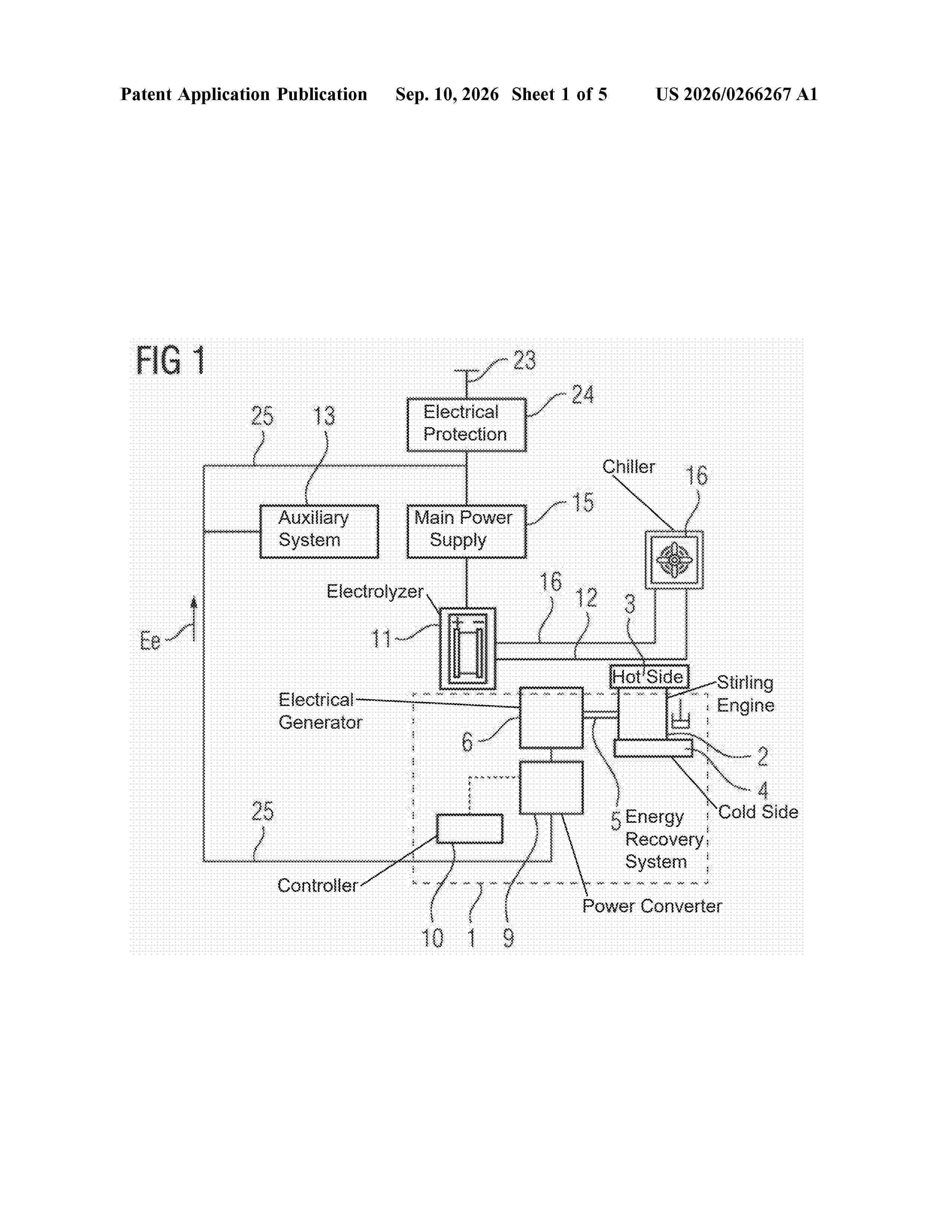
0000 An energy recovery system for an electrolyzer includes a heat engine configured to be thermally connected at a hot side to a waste heat output of the electrolyzer, and an electrical generator configured to be functionality coupled to a crankshaft of the heat engine. The energy recovery system is configured to recover electrical energy generated by the electrical generator from waste heat of the electrolyzer. A method of recovering energy, such as by use of the energy recovery system, is also provided.
Resumen de: AU2026223185A1
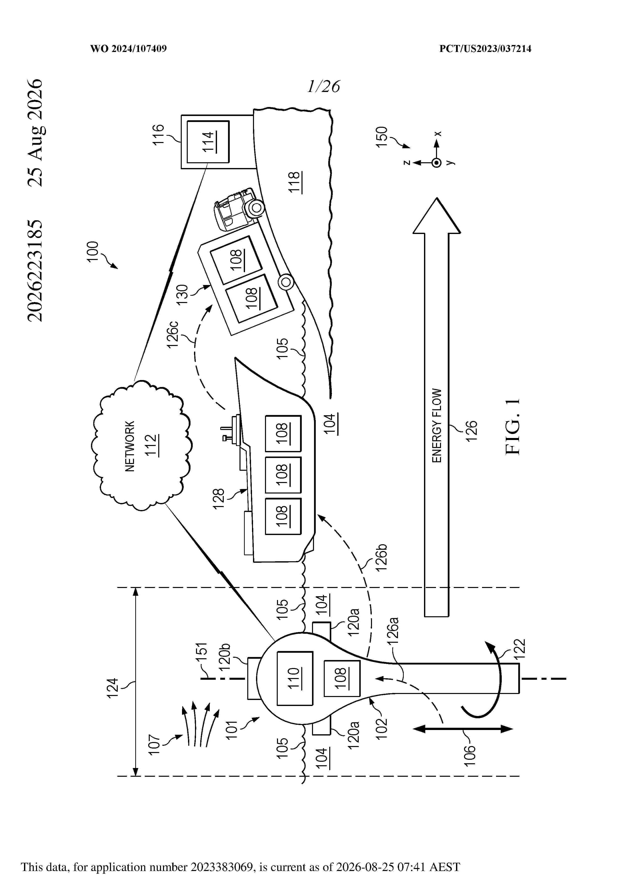
The present invention provides an unmoored, ocean-faring wave energy converter, comprising a hull having a draft of a length greater than a length of a largest horizontal width, the hull including a bulbous enclosure centered about a vertical axis and an open tube protruding downwardly therefrom; a reservoir within the bulbous enclosure adapted to adjust a buoyancy of the hull through ingress and egress of water received via the open tube; and a propeller mounted to the hull and positioned to impart a rotational force on the hull. a rotational force on the hull. ug u g
Resumen de: DE102025108504A1
Die Erfindung betrifft ein Getriebe (20) für eine Windkraftanlage (1). Das Getriebe (20) weist eine Antriebswelle (30) zum Aufnehmen mechanischer Leistung von einem Rotor (4) der Windkraftanlage (1) auf. Das Getriebe (20) weist ein Antriebsrad (32) auf, welches mit der Antriebswelle (30) drehfest verbunden ist. Das Getriebe (20) weist eine achsparallel zu der Antriebswelle (30) beabstandete Abtriebswelle (40) auf. Die Abtriebswelle (40) ist zum Übertragen mechanischer Leistung drehfest mit einer Generatoreinheit (50) koppelbar. Das Getriebe (20) weist ein Abtriebsrad (42) auf, welches mit der Abtriebswelle (40) drehfest verbunden ist und mit dem Antriebsrad (32) kämmt. Das Getriebe (20) ist derart ausgebildet, dass die Abtriebswelle (40) mit dem Abtriebsrad (42) in radialer Richtung (92) des Antriebsrads (32) von dem Getriebe (20) zur Wartung abnehmbar ist. Die Erfindung betrifft ferner einen Triebstrang (10) und eine Windkraftanlage (1).
Resumen de: DE102025108475A1
Die Erfindung betrifft ein Getriebe (20) für eine Windkraftanlage (1). Das Getriebe weist eine Antriebswelle (30) zum Aufnehmen mechanischer Leistung von einer Rotorwelle (12) der Windkraftanlage sowie ein Antriebsrad (32), welches lösbar mit der Antriebswelle drehfest verbunden und zur Wartung abnehmbar ist, auf. Das Getriebe weist eine achsparallel zur Antriebswelle beabstandete Abtriebswelle (40), welche zum Übertragen mechanischer Leistung drehfest mit einer Generatoreinheit (50) koppelbar ist, auf. Das Getriebe weist ein Abtriebsrad (42) auf, welches mit der Abtriebswelle drehfest verbunden ist und mit dem Antriebsrad (32) kämmt. Ferner weist das Getriebe ein Antriebsgehäuse (22), in welchem das Antriebsrad (32) untergebracht ist und welches eine Öffnung (23) zum axialen Entnehmen des Antriebsrads (32) aufweist, auf. Zudem weist das Getriebe eine Abdeckung (70) zum zumindest teilweisen Verschließen der Öffnung (23) des Antriebsgehäuses (22) auf. Die Erfindung betrifft zudem ein Verfahren, einen Triebstrang (10) und eine Windkraftanlage.
Resumen de: DE102025108468A1
Die Erfindung betrifft ein Getriebe (20) für eine Windkraftanlage (1). Das Getriebe weist eine Antriebswelle (30) zum Aufnehmen mechanischer Leistung von einer Rotorwelle (12) der Windkraftanlage und ein Antriebsrad (32), welches mit der Antriebswelle (30) drehfest verbunden ist, auf. Das Getriebe weist eine von der Antriebswelle (30) im Wesentlichen achsparallel beabstandete Abtriebswelle (40), welche zum Übertragen mechanischer Leistung mit einer Generatoreinheit (50) mechanisch koppelbar ist, auf. Das Getriebe umfasst zudem ein Abtriebsrad (42), welches mit der Abtriebswelle (40) mechanisch wirkverbunden ist und mit dem Antriebsrad (32) kämmt. Das Getriebe ist derart ausgebildet, dass eine von der Achsparallelität abweichende Fehlstellung der Antriebswelle (30) mit Bezug auf die Abtriebswelle (40) aufgrund von Verzahnungskräften ein Biegemoment in der Antriebswelle (30) erzeugt. Das Getriebe weist zudem einen Verformungsabschnitt (70), welcher zum Ausgleichen der Fehlstellung biegeweich ausgeführt ist, auf. Die Erfindung betrifft auch einen Triebstrang (10) und eine Windkraftanlage.
Resumen de: US20260269626A1
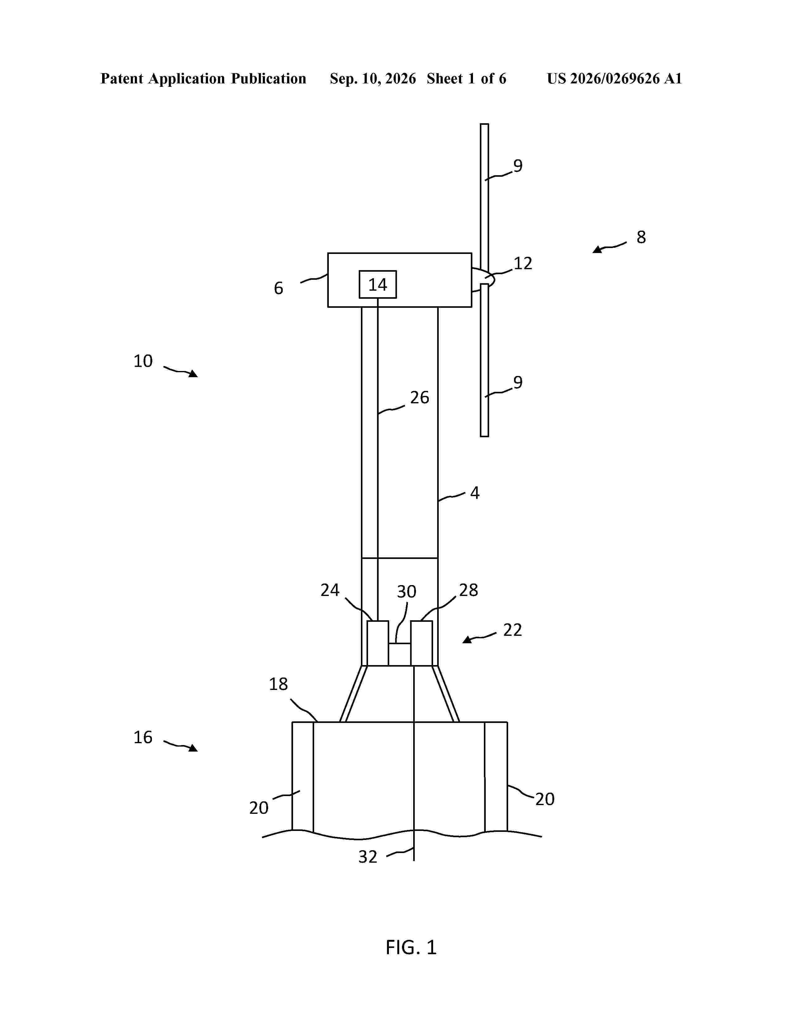
A wind power plant includes a control system operatively connected to switchgear devices of a plurality of wind turbine clusters, and wherein the control system is configured to identify the existence of a no-generation condition affecting at least one of the plurality of wind turbine clusters; control the switch status of the switchgear devices, based on the identification, to control the connection status of each of the plurality of wind turbine clusters to an inter-cluster power network so as to reduce no load losses of the wind turbine clusters.
Resumen de: US20260264355A1
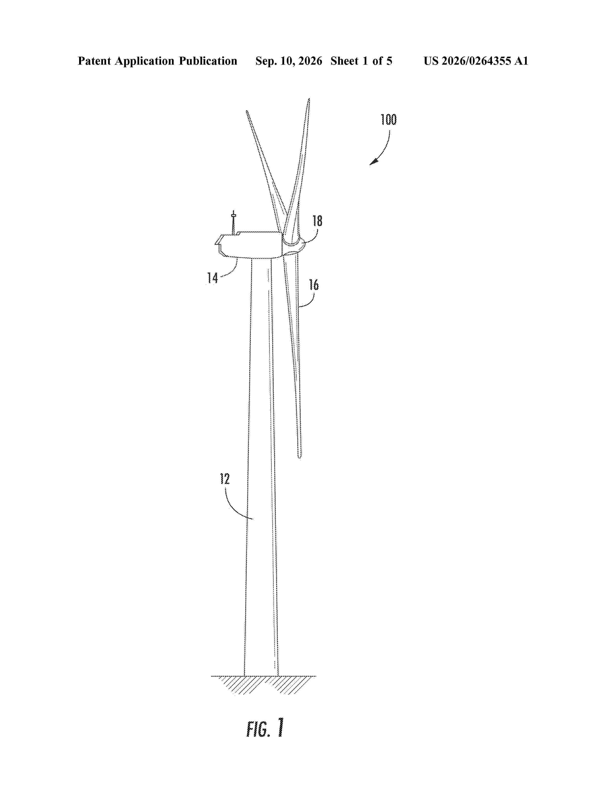
A method of manufacturing a jointed structural component of a rotor blade includes forming at least one first portion of the jointed structural component via at least one custom mold. The first portion(s) has one or more custom characteristics with respect to the rotor blade. The method also includes providing at least one second portion of the jointed structural component. The second portion(s) of the jointed structural component is a pre-fabricated component. The method further includes arranging the first portion(s) and the second portion(s) of the jointed structural component together at an interface. Moreover, the method includes joining the first portion(s) and the second portion(s) together at the interface to create the jointed structural component.
Resumen de: WO2026185731A1
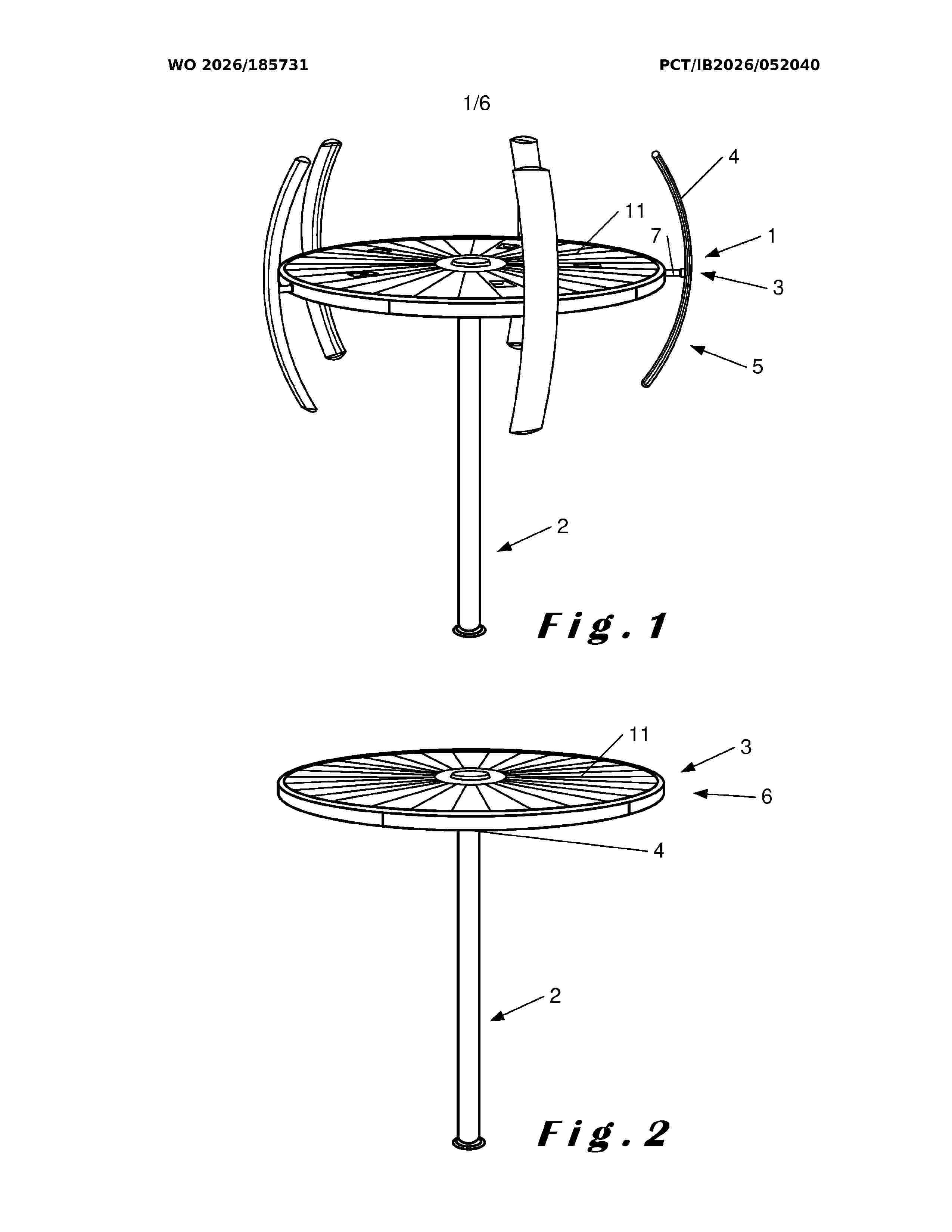
The invention provides a vertical-axis wind turbine (1 ), comprising a mast (2) and a frame (3) rotatable about the mast (2) having a plurality of blades (4) attached to the frame (3), wherein the blades (4) extend substantially vertically in a first blade position (5), characterized in that the blades (4) are mounted to the frame (3) so as to be adjustable between the first (5) and a second blade position (6) and the blades (4) extend substantially horizontally in the second blade position (6).
Resumen de: WO2026184133A1
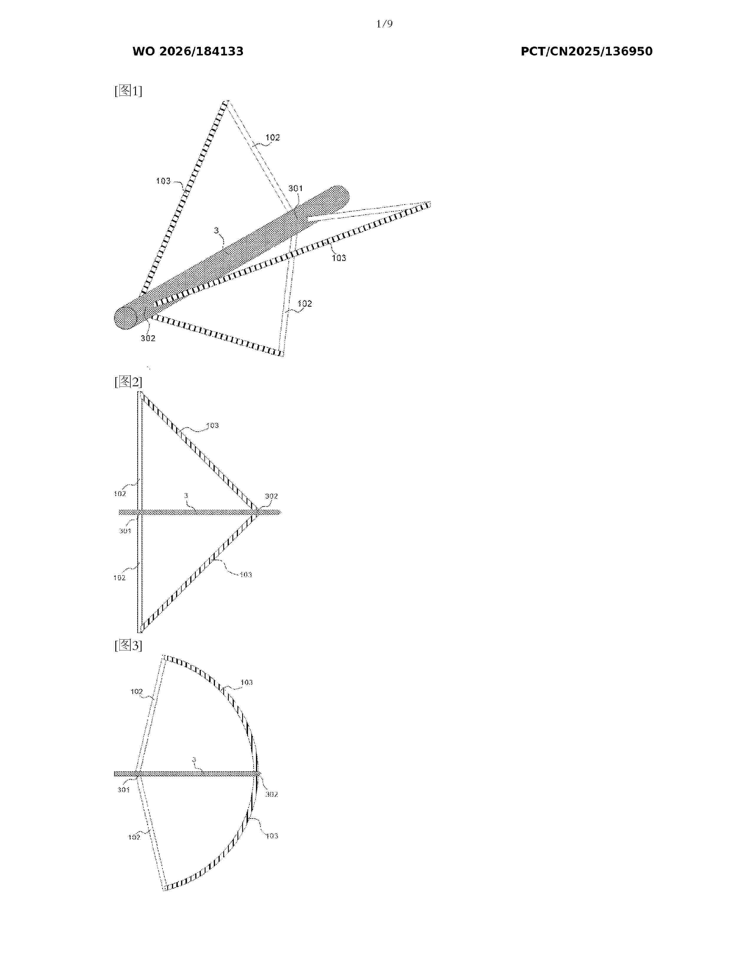
A wind rotor having canvas blades and a horizontal-axis wind turbine comprising the wind rotor having canvas blades. In view of the problems of high cost, high noise, and harm to birds in conventional three-blade wind turbines, and of low power generation efficiency of vertical‑axis wind turbines having canvas blades, the present invention provides a wind rotor having canvas blades, wherein the canvas blades of the wind rotor are combined with a frame-type hub, and inner and outer edges of the canvas blades are respectively connected to a main shaft and helical spokes to form a rose-shaped wind-catching curved surface; the wind rotor further integrates radial or circumferential furling mechanisms for retracting the blades under strong wind conditions. The described structure can effectively improve the wind resistance and operational safety of the complete machine, while simplifying the structure, reducing manufacturing costs, and significantly lowering the weight; additionally, the described structure enhances power generation efficiency in low-wind-speed regions, and achieves the technical effects of low noise, environmental friendliness, and ease of recycling.
Resumen de: WO2026186280A1
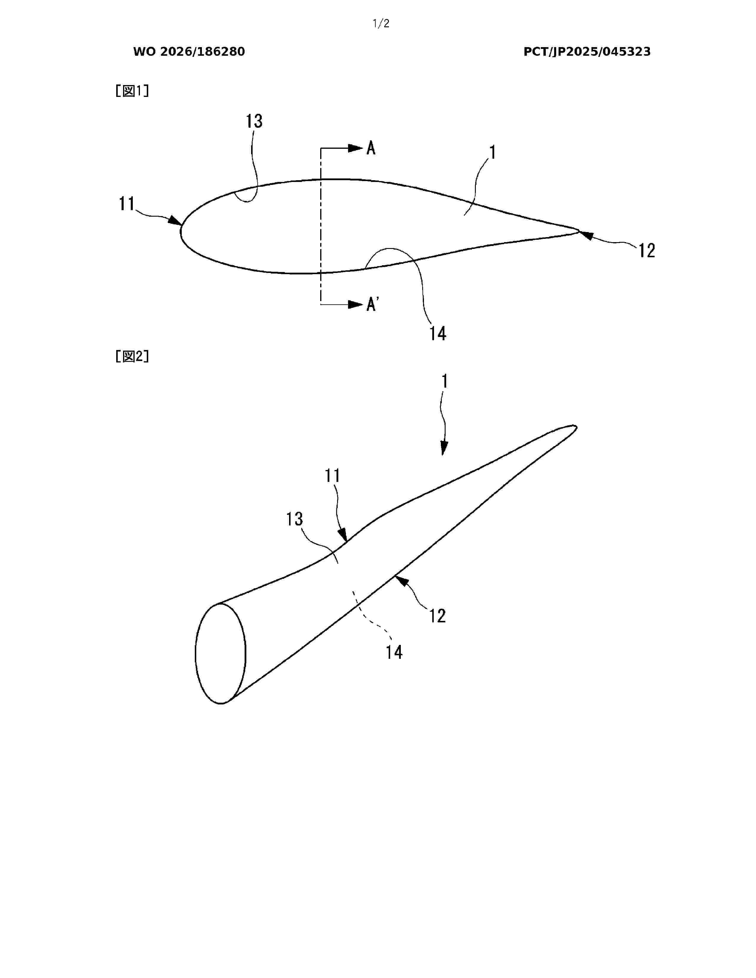
The purpose of the present invention is to provide a coating film exhibiting excellent erosion resistance. A silicone composition according to the present invention is characterized by containing 100 parts by mass of a reactive silicone oil (A), 5-80 parts by mass of a curing agent (B) that reacts with the reactive silicone oil (A), and 1-100 parts by mass of a reinforcing agent (C), wherein the reactive silicone oil (A) contains at least one selected from the group consisting of a first reactive silicone oil (A-1) having two or more hydroxyl groups per molecule and having no other reactive functional group, and a second reactive silicone oil (A-2) having two or more alkoxy groups per molecule and having no other reactive functional group, and the reinforcing agent (C) contains at least one selected from the group consisting of silicone resins (C-1), silica particles (C-2), and silicate particles (C-3).
Resumen de: WO2026184834A1
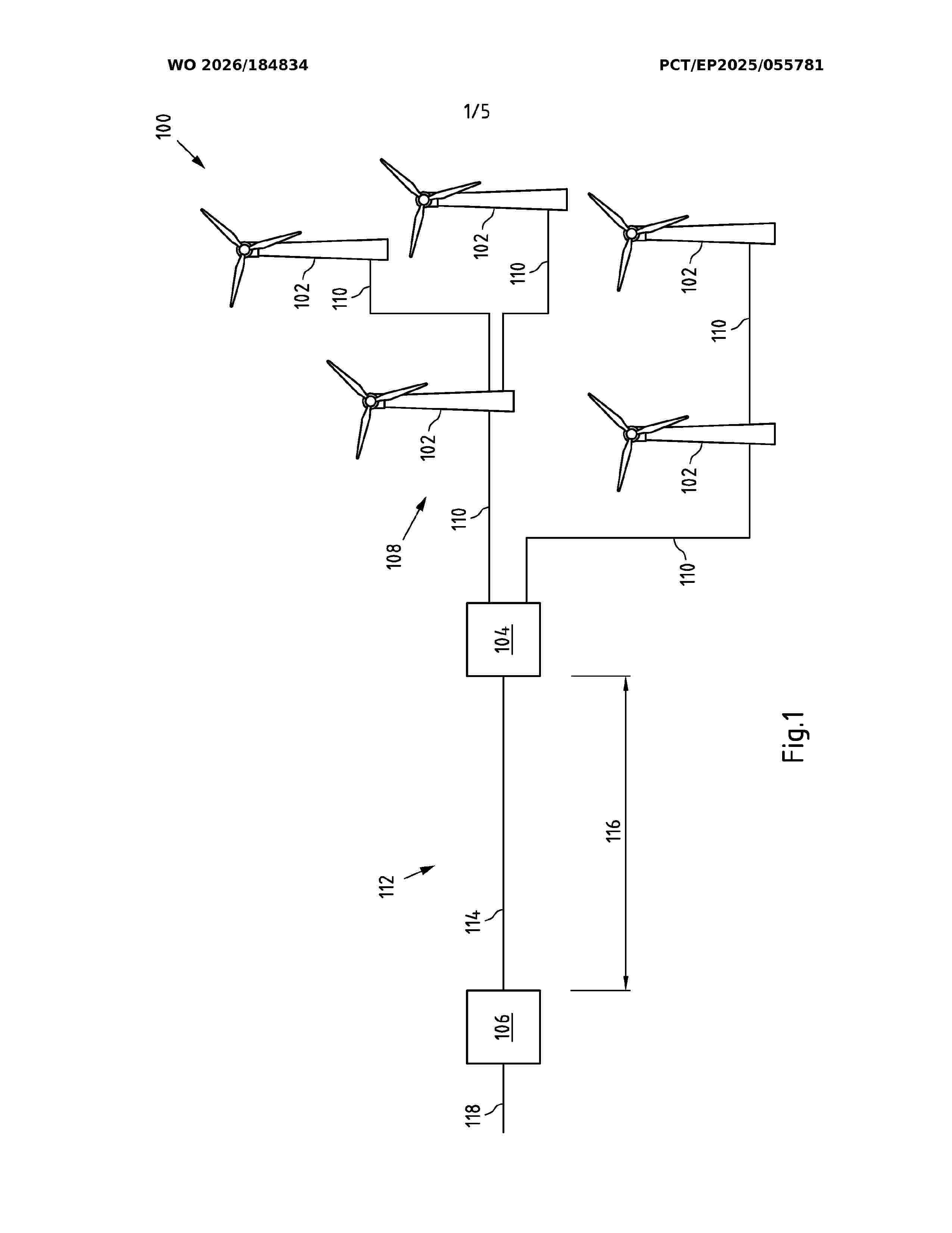
The invention relates to an offshore wind farm (100, 200, 300), comprising a plurality of offshore wind turbines (102, 202, 222, 302), wherein each offshore wind turbine (102, 202, 222, 302) is configured to produce power with a nominal voltage level of at least 66 kV, at least one switchgear arrangement (104, 204, 304) configured to transfer at least a portion of the produced power without a voltage level change via at least one submarine power cable arrangement (112, 212, 312) of the offshore wind farm (100, 200, 300) with a cable length of at least 30 km to an onshore substation (106, 206, 306).
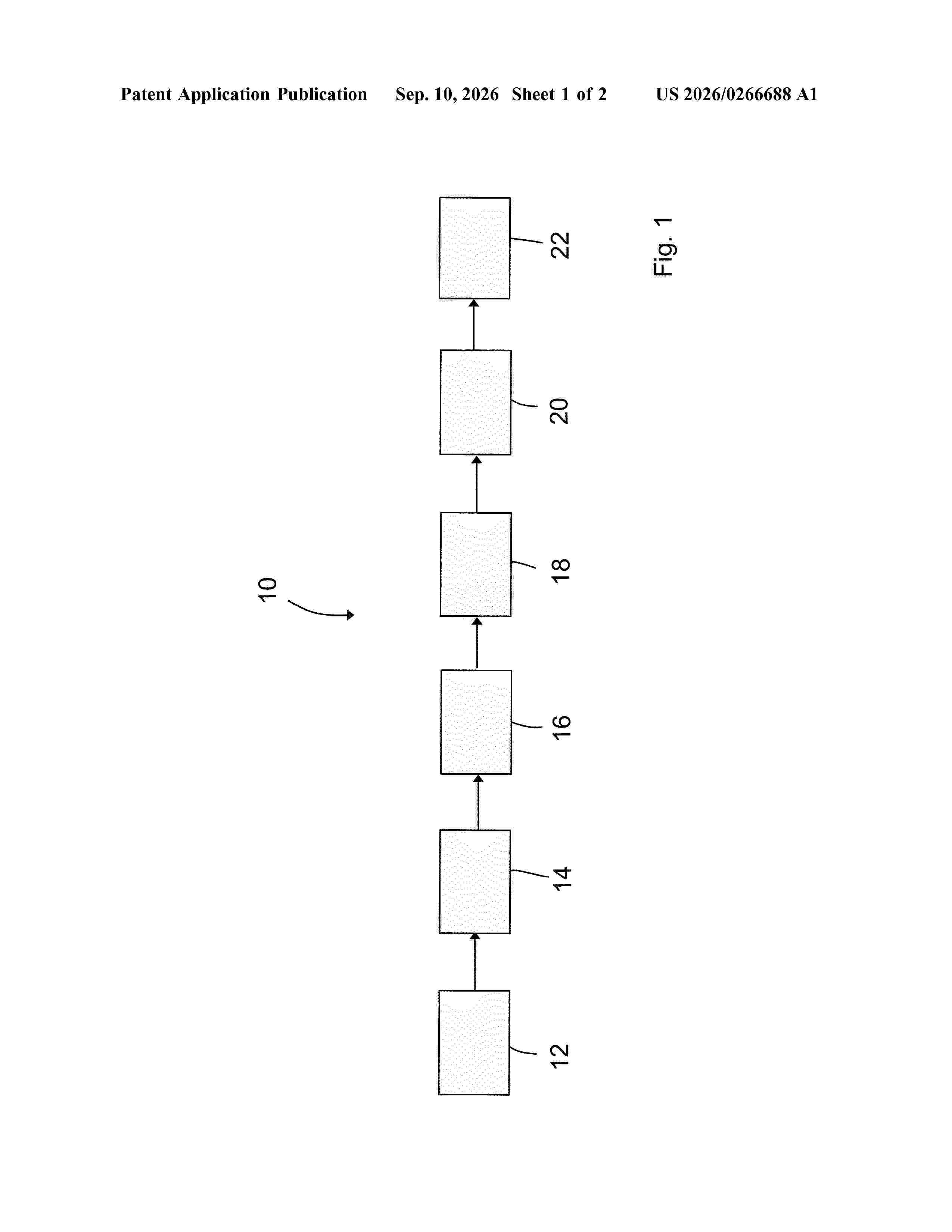
Resumen de: US20260266688A1
A method for monitoring a slide bearing of a wind turbine, a steam turbine or a compressor includes at least the following steps: detecting a structure-borne sound signal of the slide bearing by means of a structure-borne sound sensor; transforming the detected structure-borne sound signal into a time-frequency domain, in particular by means of continuous wavelet transformation; identifying anomalies in the transformed structure-borne sound signal by means of an autoencoder; and generating anomaly data depending on identified anomalies. A system for monitoring a slide bearing is also disclosed.
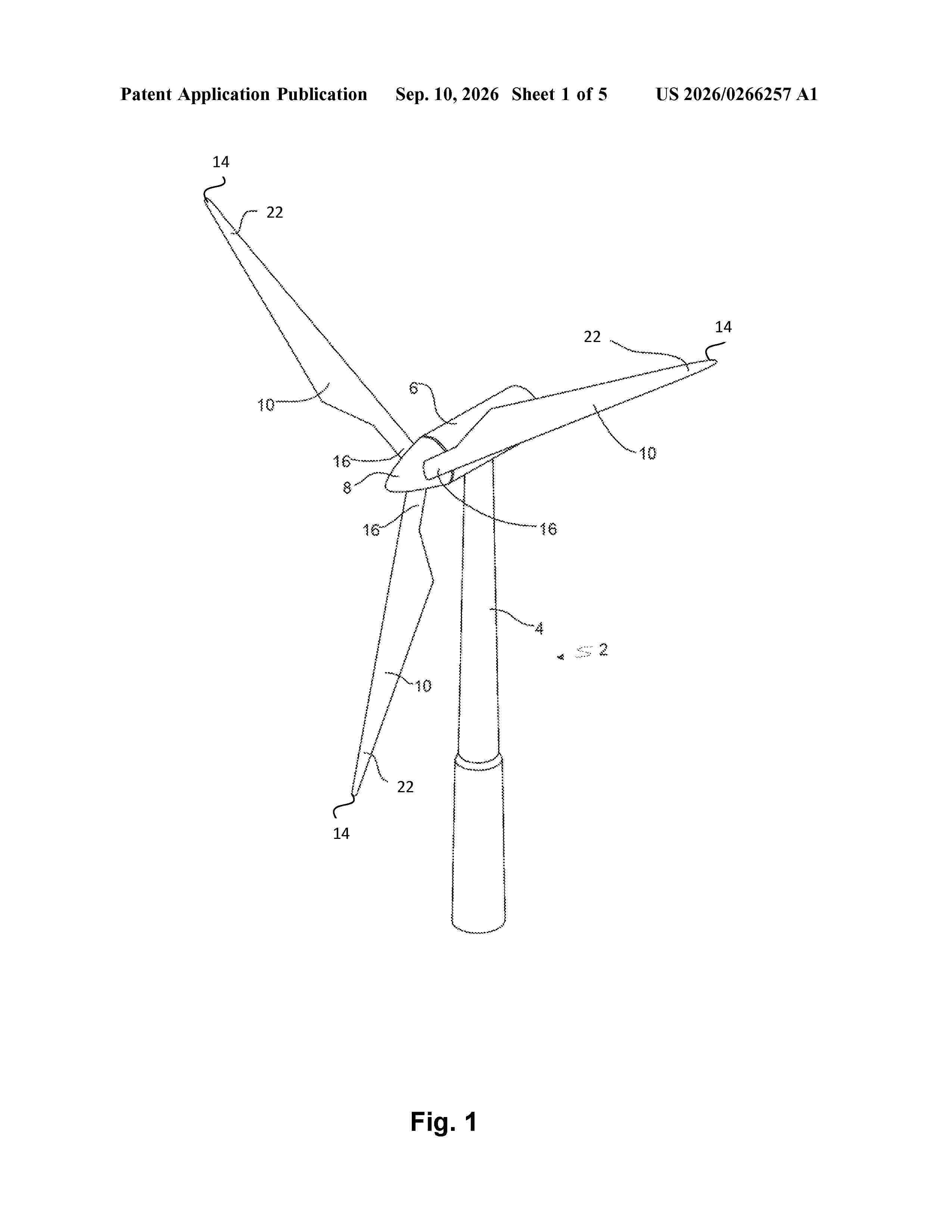
Resumen de: US20260266257A1
0000 The present invention relates to a leading edge protection for a wind turbine blade, wherein a leading edge axis of the leading edge protection is configured to be fitted on at least part of a leading edge of a wind turbine blade and the leading edge protection is configured to extend between the leading edge and a first edge downstream a first side of the wind turbine blade as well as between the leading edge and a second edge downstream a second side of the wind turbine blade, wherein the leading edge protection comprises a first part and wherein the first edge is configured to be non-parallel with the leading edge of the wind turbine blade along the first part of the leading edge protection. The present invention further relates to a wind turbine blade comprising the leading edge protection and a wind turbine comprising the wind turbine blade. Finally, the present invention relates to a method for protecting a leading edge of a wind turbine blade arranged on a wind turbine and a leading edge protection obtainable by that method.
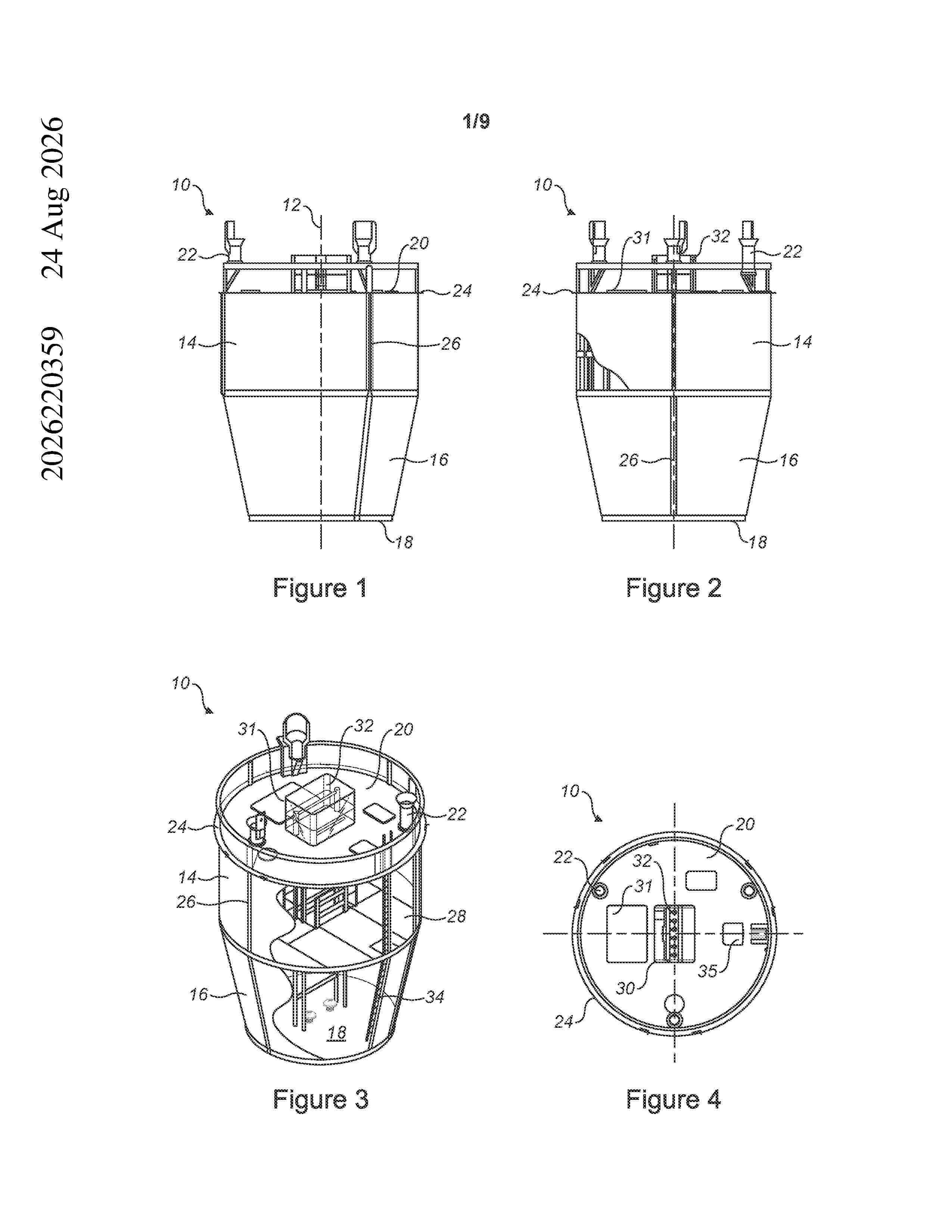
Resumen de: AU2026220359A1
Installing equipment in offshore monopile foundations Abstract An equipment canister for supporting and enclosing electrical equipment of a wind turbine. The canister comprises: a housing defining or containing at least one internal 5 platform for supporting the equipment; a lifting interface on a top of the housing; an at least one support formation positioned on or projecting laterally beyond a side wall of the housing. The support formation is capable of supporting the weight of the canister suspended therefrom when the canister is installed within a monopile wind turbine foundation. 10 Various wind turbine arrangements and wind turbine assembly methods incorporating such a canister are also described. Figure 5 15 Abstract 10 foundation. such a canister are also described.20 ug b s t r a c t u g f o u n d a t i o n v fab w mn v Figure 5 ug u g
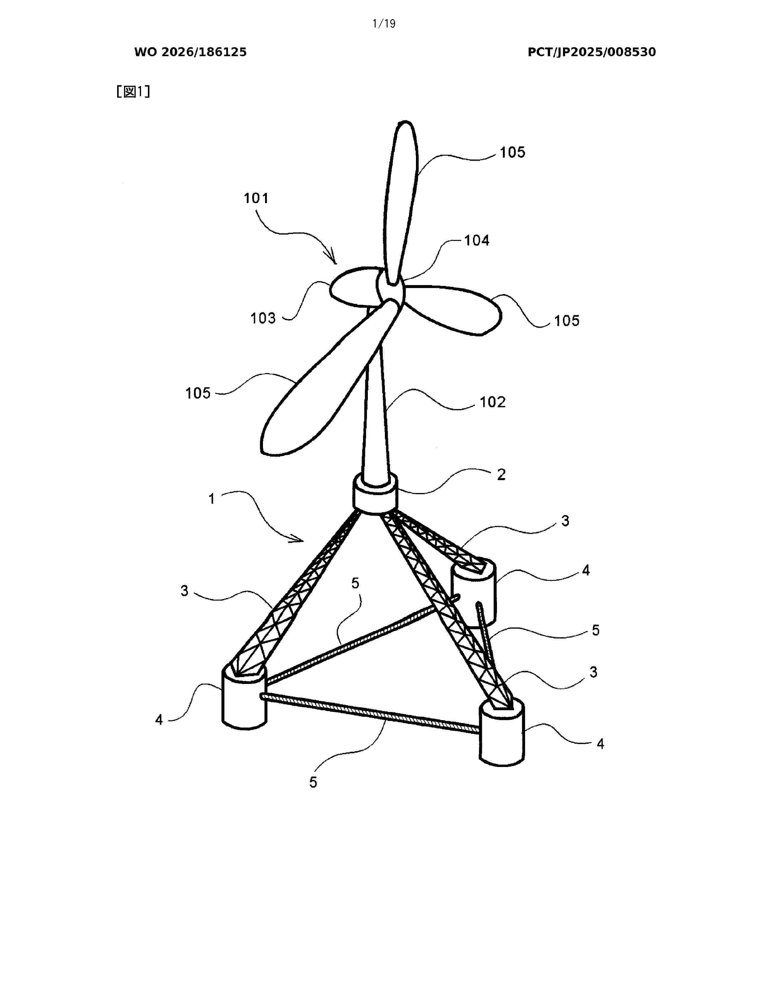
Resumen de: WO2026186125A1
The present invention addresses the problem of providing a floating body structure, and the problem is solved by a floating body structure 1 characterized by comprising a facility holding body 2 that holds an offshore facility 101, three or more inclined leg members 3 each having an upper end connected to the facility holding body 2 and a lower end swingable in directions in which the lower ends move toward and away from each other, floating bodies 4 attached to the lower ends of the inclined leg members 3, and a wire 5 that limits the distance between the floating bodies 4, wherein: in a state in which the lower ends of the inclined leg members 3 are directed obliquely downward around the facility holding body 2, the floating body structure 1 floats on the sea by buoyancy generated in the floating bodies 4; and tension is generated in the wire 5 by gravity acting on the offshore facility 101 and the facility holding body 2, and the distance between the floating bodies 4 is maintained constant.
Resumen de: WO2026186279A1
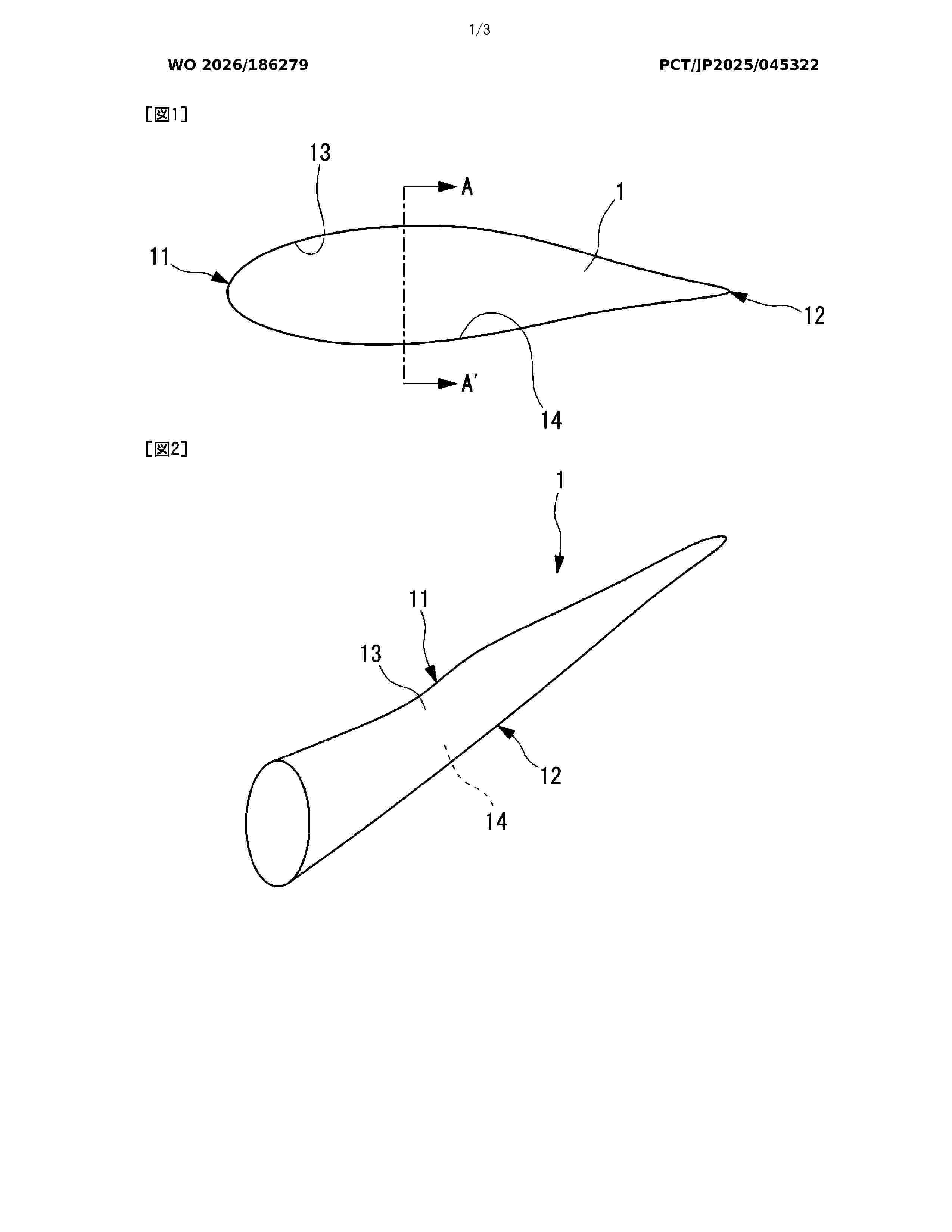
The purpose of the present invention is to provide a wind power generator blade comprising a coating film that has excellent snow-and-ice adhesion suppressing ability and that exhibits excellent adhesion to a blade base body. A wind power generator blade according to the present invention comprises a blade base body and a coating film that covers at least a partial region of the surface of the blade base body. The coating film contains a cured object of a silicone composition. The silicone composition contains a reactive silicone oil (A), a nonreactive silicone oil (B), and a curing agent (C) that reacts with the reactive silicone oil (A), and does not contain a silicone resin (D) or silica particles (E). The reactive silicone oil (A) contains at least one selected from the group consisting of first reactive silicone oils (A-1) and second reactive silicone oils (A-2). The film thickness of the coating film is 50 µm or more.
Resumen de: WO2026186707A1
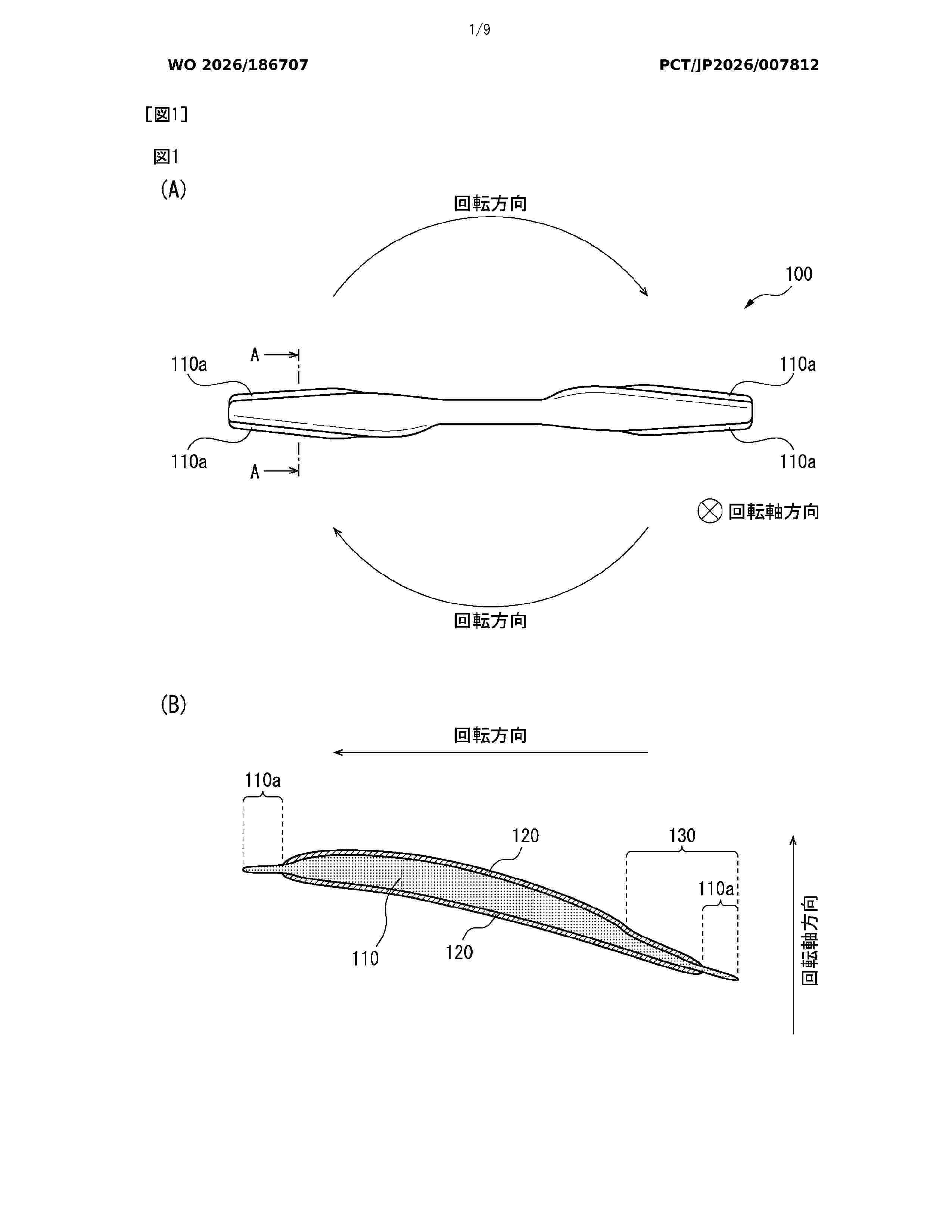
Provided is a blade 100 comprising a core material 110 and a skin material 120 disposed on the surface of the core material 110, wherein the elastic modulus of the core material 110 is lower than the elastic modulus of the skin material 120, and a core material protrusion 110a, which is a portion of the core material 110 that does not overlap the skin material 120 when viewed from the direction of the rotation axis of the blade 100, is disposed on at least a portion of the edge of the blade 100.
Resumen de: US20260266265A1
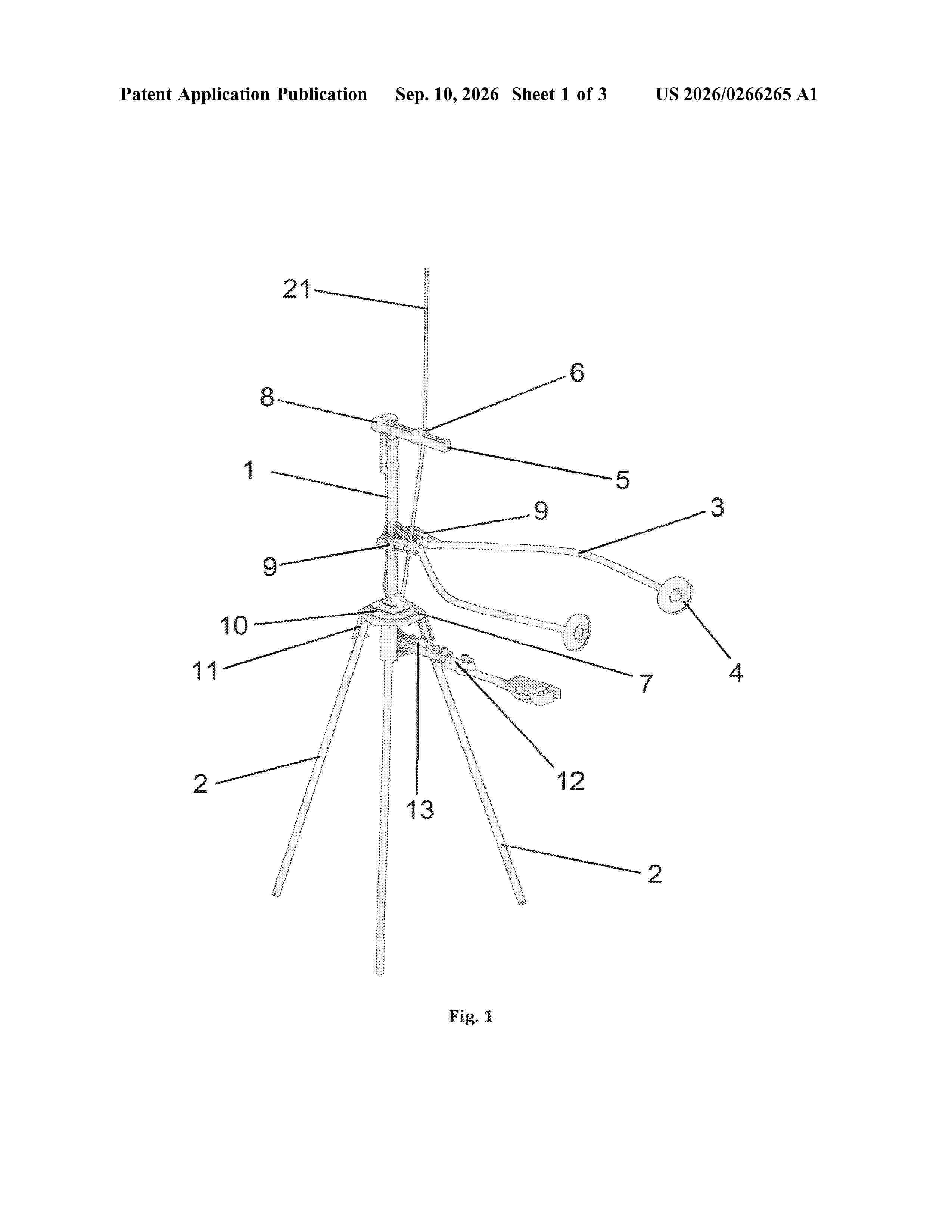
A wind turbine blade and tower maintenance device, used for servicing, including cleaning, inspection, deicing and painting of wind turbine blades and tower. The device has: a plurality of balancing rods, a central hub, at least one tool arm adapted to releasably fix one or more tools adapted for surface maintenance; and a tool arm motor adapted to adjust the angle of the tool arm in respect a longitudinal axis of the central hub, wherein: the central rod and balancing rods are connected to the central hub; the tool arm is rotatably fixed to the central hub and the balancing rods and central hub are adapted to be connected to carrying and balancing ropes or cables. A system for lowering and raising of the arrangement is also disclosed.
Resumen de: WO2026186710A1
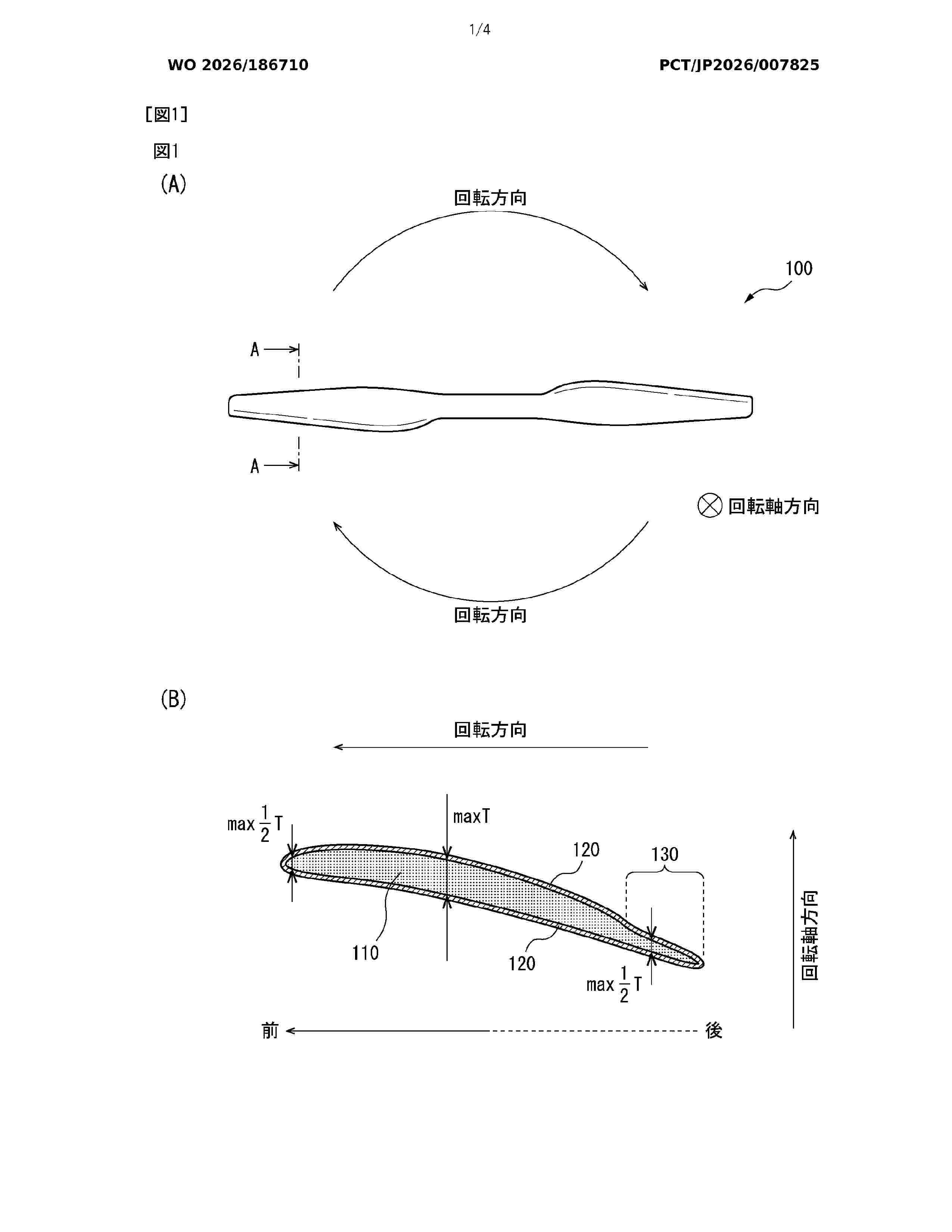
Provided is a blade comprising: a core material; and a skin material disposed on the surface of the core material. The skin material includes: reinforcing fibers; and a matrix resin impregnated in the reinforcing fibers. The core material is at least partially foamed. When an inner foam density of the core material measured at the maximum thickness of the blade is defined as ρin-tmax, an inner foam density of the core material measured at 1/2 of the maximum thickness of the blade is defined as ρin-t1/2, an outer foam density of the core material measured at the maximum thickness of the blade is defined as ρout-tmax, and an outer foam density of the core material measured at 1/2 of the maximum thickness of the blade is defined as ρout-t1/2, ρin-t1/2 is 50 to 120% of ρin-tmax, ρout-tmax is 0 to 55% of ρin-tmax, and ρout-t1/2 is 0 to 55% of ρin-t1/2.
Resumen de: WO2026187033A1
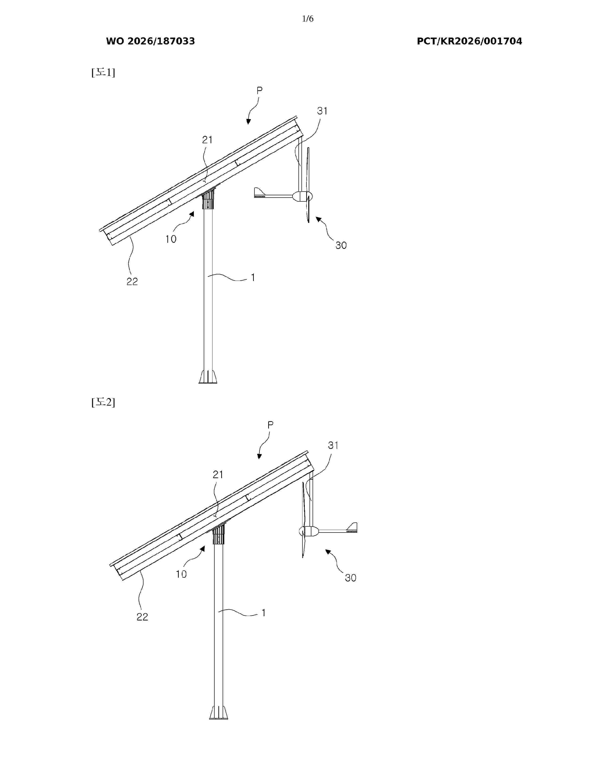
Disclosed is a convergence power generation system comprising: a solar panel array; a wind power generator that is disposed around the solar panel array and movable in conjunction with rotation of the solar panel array; and a solar tracker that provides rotational force to the solar panel array.
Nº publicación: WO2026186982A1 10/09/2026
Solicitante:
NEARTHLAB INC [KR]
(\uC8FC)\uB2C8\uC5B4\uC2A4\uB7A9
Resumen de: WO2026186982A1
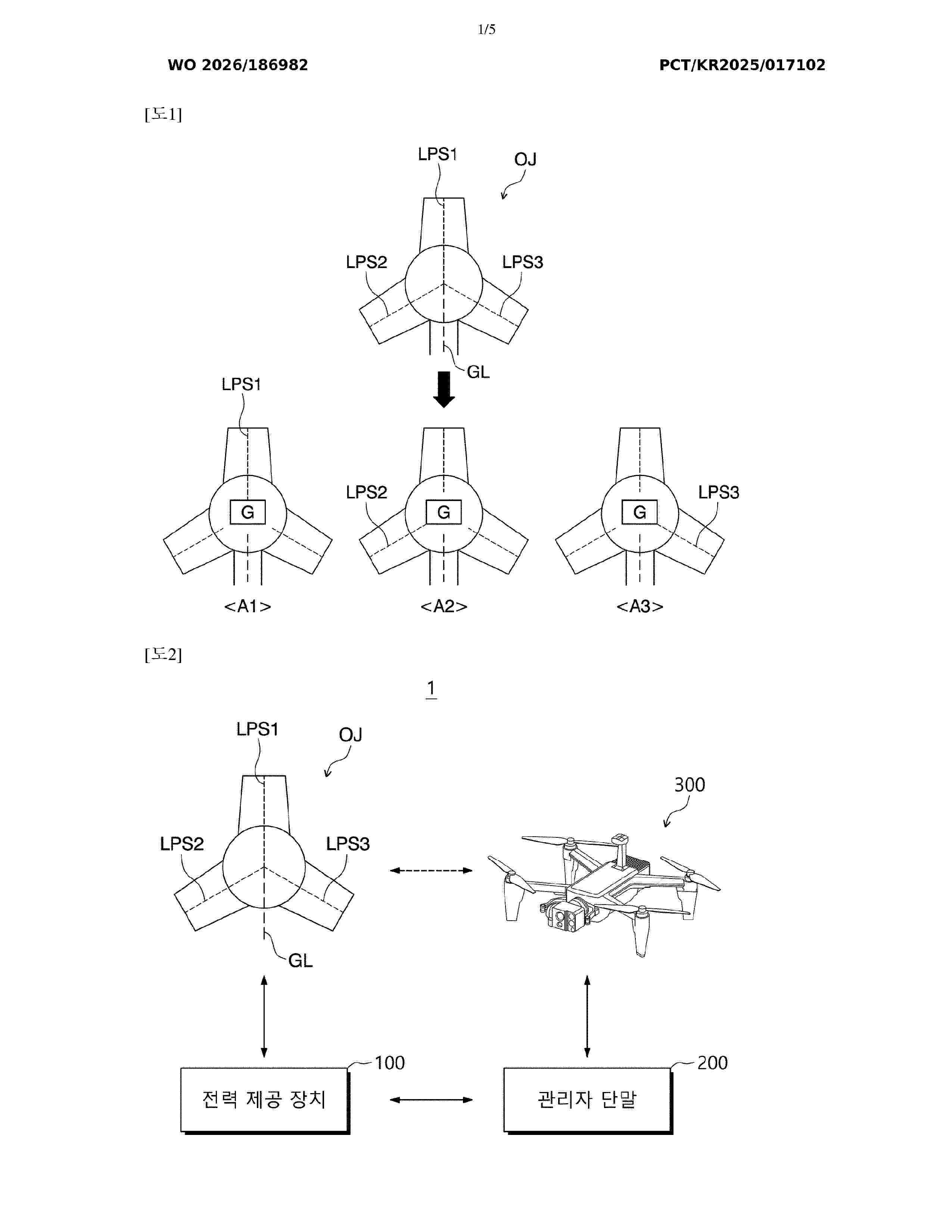
The present invention relates to a power supply device for inspecting a lighting protection system (LPS) line by analyzing imaging data of a swarm of mobile objects, and an inspection system comprising same. The power supply device for providing power for inspecting an LPS line included in a predefined object, according to some embodiments of the present invention, may comprise: a generator for generating a high-voltage signal; a channel electrically connected to the generator and the LPS line so as to transmit the generated high-voltage signal to the LPS line; a switch formed on the channel so as to control that the high-voltage signal flows through the channel; and a controller for controlling the switch.
 BOPI
BOPI
 Sede Electrónica