Si deseas distinguir tus productos, servicios o ambos de los de otra empresa, es posible que necesites una marca o nombre comercial. Descubre qué son, en qué consiste su procedimiento de registro y qué implica.

Información sobre los plazos de presentación de solicitudes de transformación de marcas de la Unión Europea en marca nacional española. Más información


Si tienes un nuevo dispositivo, producto o procedimiento que resuelva un problema técnico o tenga una ventaja práctica, existen distintas formas de protegerlo en España y en otros países. Descubre cómo hacerlo.

¿Tu innovación reside en la estética, la ornamentación o la apariencia de tu producto? Protégela mediante un diseño industrial. Descubre qué derechos confiere el registro y cómo realizar la tramitación.

Las indicaciones geográficas protegen el nombre de un producto originario de una zona geográfica, a la cual le debe una determinada calidad, reputación u otra característica. Descubre qué son, en qué consiste su procedimiento de registro y qué beneficios conceden.

Las patentes publicadas en todo el mundo son una valiosa fuente de información científica, técnica y comercial.

Si eres emprendedor/a o una empresa y quieres potenciar y mejorar la rentabilidad de tu negocio protegiendo de forma adecuada los activos intangibles de tu organización, en este espacio encontrarás lo necesario.


 1083
resultados
1083
resultados
 Última actualización
21/03/2026 [07:23:00]
Última actualización
21/03/2026 [07:23:00]


 Resultados 550 a 575 de 1083

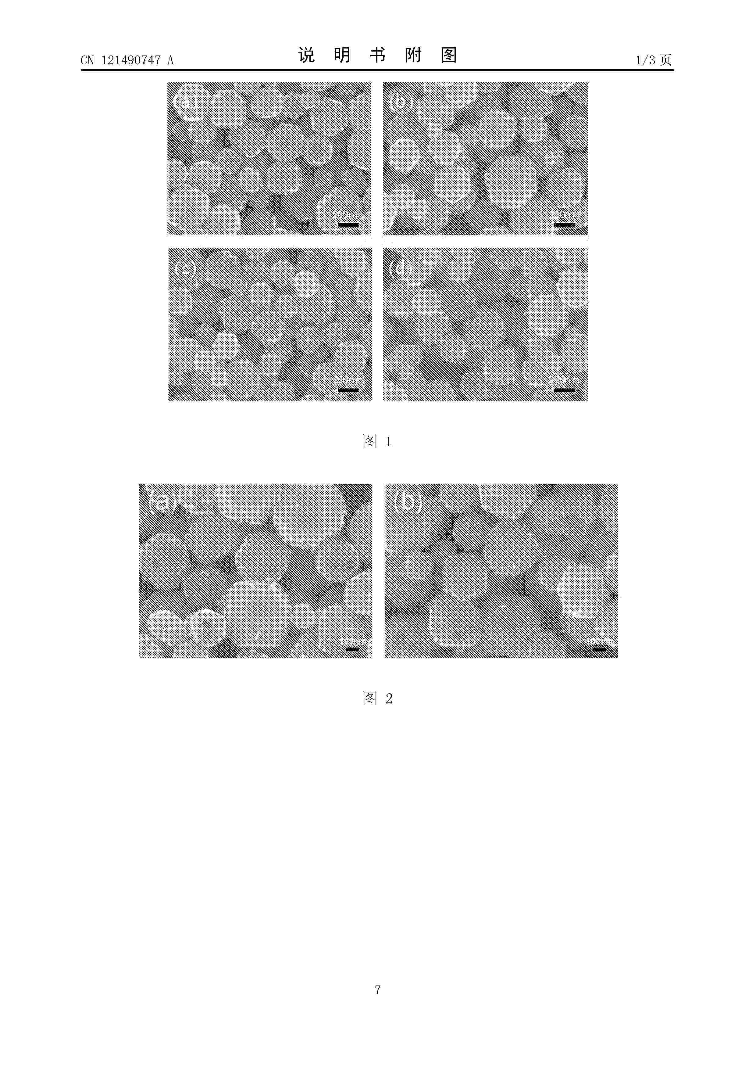
Resumen de: CN121490747A
本发明涉及材料制备领域,具体为一种原位刻蚀生长嵌套式SrTiO3/TiO2异质结光催化材料的制备方法,解决了现有制备方法无法原位合成嵌套式SrTiO3/TiO2异质结构的问题。具体为将SrCl2·6H2O的水溶液与LiOH·H2O的水溶液混合,搅拌得到溶液A,将TiCl4加入1,2‑丙二醇的溶液中,搅拌得到溶液B;将溶液A和溶液B混合搅拌并水热反应一段时间,得到十八面体形状SrTiO3;盐酸水热刻蚀后,SrTiO3内部也会被部分刻蚀,并在其(001)晶面生长出锥形小颗粒,形成SrTiO3与TiO2内外嵌套结构;经过冷却、离心、清洗及干燥后,即可得到原位刻蚀生长嵌套式SrTiO3/TiO2异质结光催化材料。本发明在一般水热条件下即可进行,操作简单、成本低廉、具有较高的产率和纯度,且光催化活性较高,具备实际应用的潜力。

Resumen de: AU2024281599A1
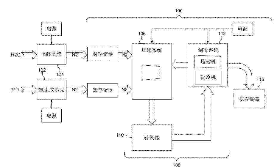
A multi-tier integrated power-to-ammonia system includes a converter for generating ammonia and heat through a reaction involving a compressed mixture of hydrogen and nitrogen gases. The system includes a steam generator that can generate steam using the heat from the reaction, and a reversible solid-oxide system in fluid communication with the steam generator that can separate the steam into oxygen gas and hydrogen gas.
Resumen de: CN121496465A
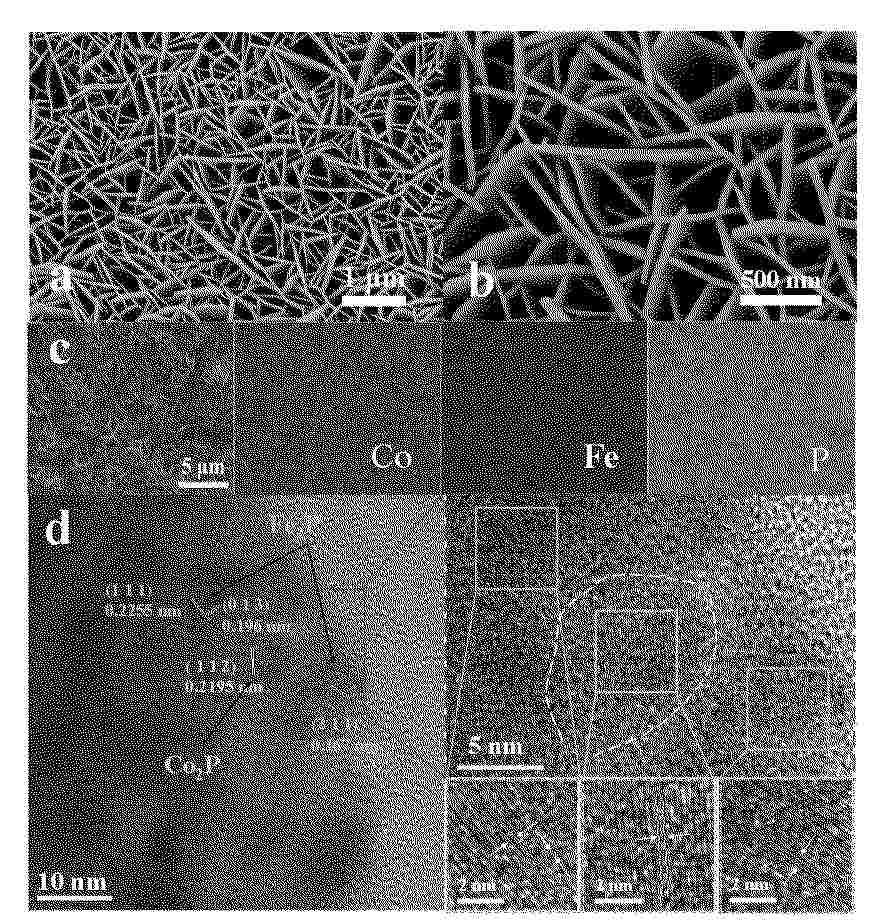
本发明公开了一种Co2P/Fe2P异质结纳米片阵列材料及其制备方法和应用,属于电催化材料技术领域。本发明提供的制备方法包括:将预处理后的泡沫镍置于含钴盐、铁盐、尿素和氟化铵的前驱体溶液中,通过水热反应在其表面生长CoFe‑LDH纳米片阵列前驱体;随后在惰性气氛下进行低温磷化处理,将前驱体转化为Co2P/Fe2P异质结,最终得到生长于泡沫镍上的Co2P/Fe2P异质结纳米片阵列材料。该材料在碱性电解质中表现出优异的双功能电催化活性与稳定性,用于全水分解时仅需1.50V的低槽压即可驱动20 mA cm‑2的电流密度。本发明工艺简单、成本低廉,为高效、稳定的非贵金属水分解催化电极的制备提供了新方案。
Resumen de: CN121496447A
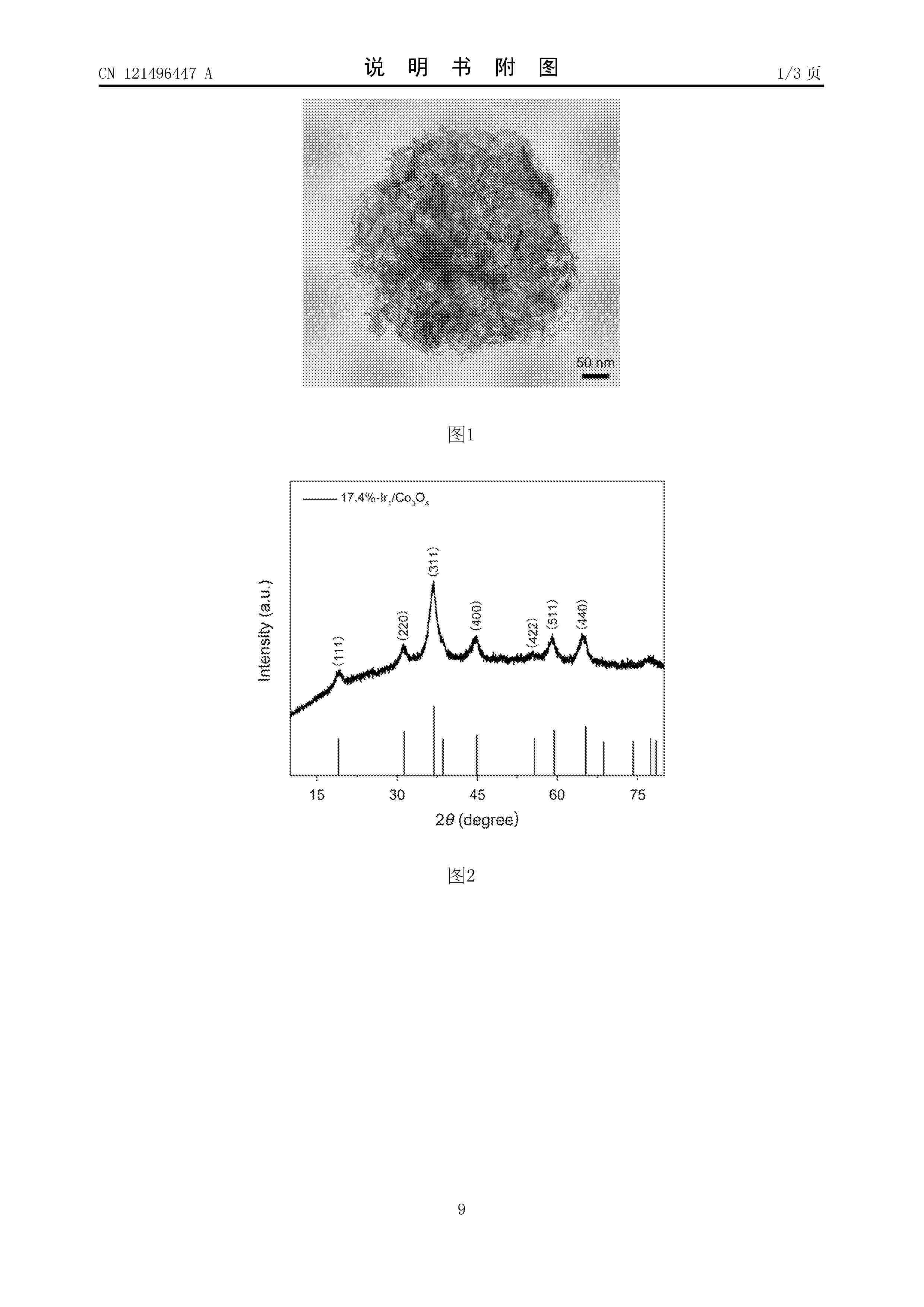
本发明公开了一种面向酸性电解水的钴基高密度单原子催化剂及其制备方法、应用,属于催化剂技术领域。所述的钴基高密度单原子催化剂包括:纳米四氧化三钴载体和负载在该载体上的单分散的铱单原子;所述铱单原子的负载量在6wt%以上,所述铱单原子的密度为4个/nm2以上。本发明公开了上述单原子催化剂在电催化分解水反应中的应用;通过提高单原子的利用率和负载密度,其在电催化分解水反应中具有高活性和高稳定性。此外,所述钴基高密度单原子催化剂合成便捷,成本低廉,在产业化应用中有巨大潜力。
Resumen de: CN121496491A
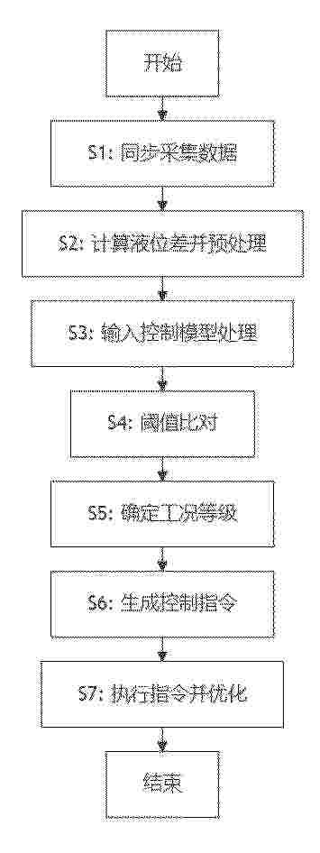
本发明涉及电解水制氢技术领域,尤其涉及一种制氢系统连通管控制方法,包括以下步骤:同步采集氢分离器和氧分离器的液位数据、氢气中的氧气浓度数据和氧气中的氢气浓度数据;基于采集的液位数据计算液位差,并对气体浓度数据进行信号预处理;将液位差和预处理后的气体浓度数据输入控制模型进行处理;通过控制模型将液位差与液位差阈值进行比对,将气体浓度数据与对应的气体浓度阈值进行比对。本发明中,通过引入气体纯度参数与液位差的多阈值耦合判断机制,进而根据超标等级触发分级控制指令,从而改善了传统方法大都采用单一液位平衡控制,由于缺乏对氢中氧和氧中氢扩散的主动阻断机制,从而造成气体纯度失控风险高的问题。
Resumen de: CN121285539A
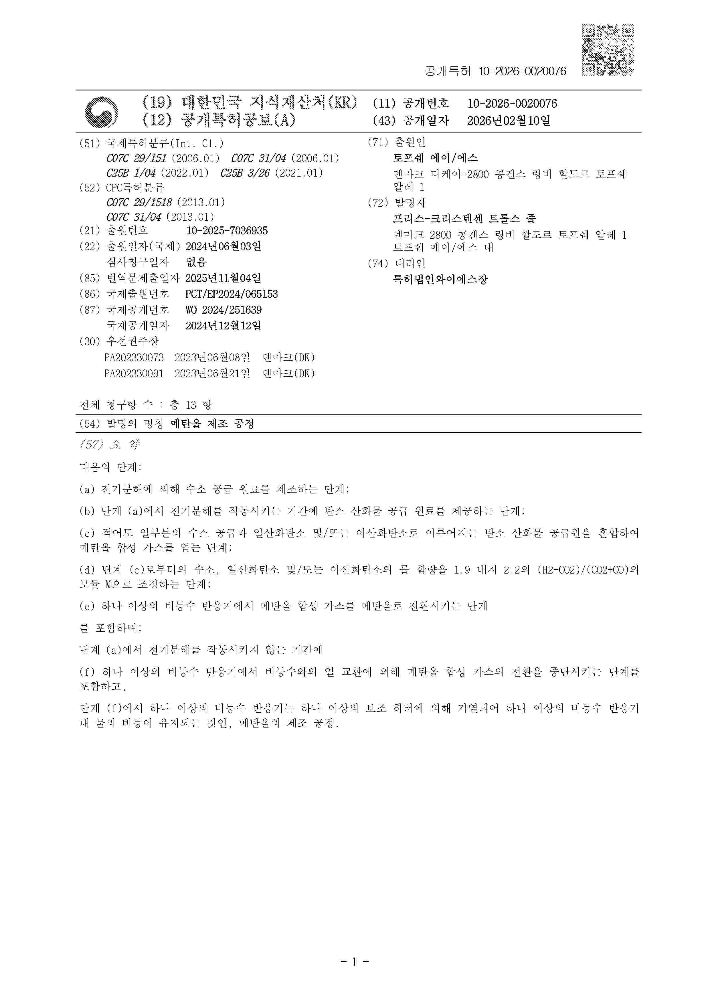
The invention relates to a method for preparing methanol. The method comprises the following steps: (a) preparing a hydrogen raw material through electrolysis; (b) providing a carbon oxide feedstock during the electrolysis operation in step (a); (c) mixing at least part of the hydrogen feed and a carbon oxide source consisting of a carbon monoxide and/or carbon dioxide feed to obtain methanol syngas; (d) adjusting the molar content of hydrogen, carbon monoxide and/or carbon dioxide in step (c) to a modulus M of 1.9 to 2.2, said modulus M being (H2-CO2)/(CO2 + CO); (e) converting the methanol syngas to methanol in one or more boiling water reactors; during the electrolysis inoperation in step (a): (f) interrupting the conversion of methanol syngas by heat exchange with boiling water in one or more boiling water reactors, in which step (f) the one or more boiling water reactors are heated by one or more auxiliary heaters to maintain boiling of water in the one or more boiling water reactors.
Resumen de: WO2025002798A1
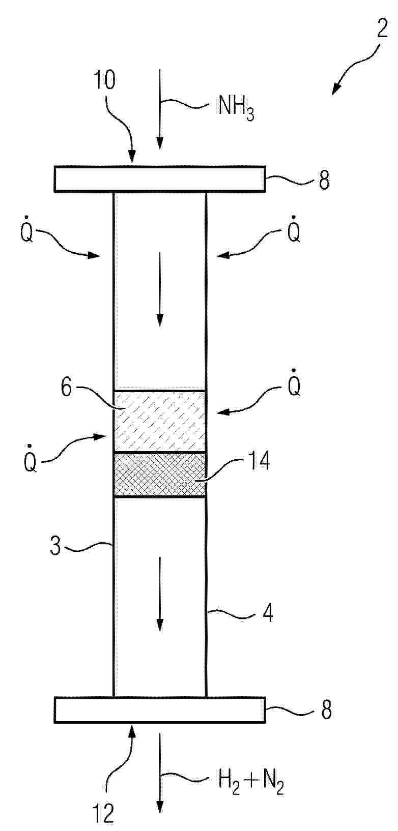
The invention relates to a reactor (2) for generating hydrogen and at least one other product from at least one reactant, the reactor comprising a tubular reactor vessel (4) which contains a catalyst (6) in the form of a ceramic bed. Improved corrosion resistance against a variety of media and thus an increased service life of the reactor (2) is achieved by forming the reactor vessel (4) from silicon-infiltrated silicon carbide (SiSiC).
Resumen de: KR20260020050A
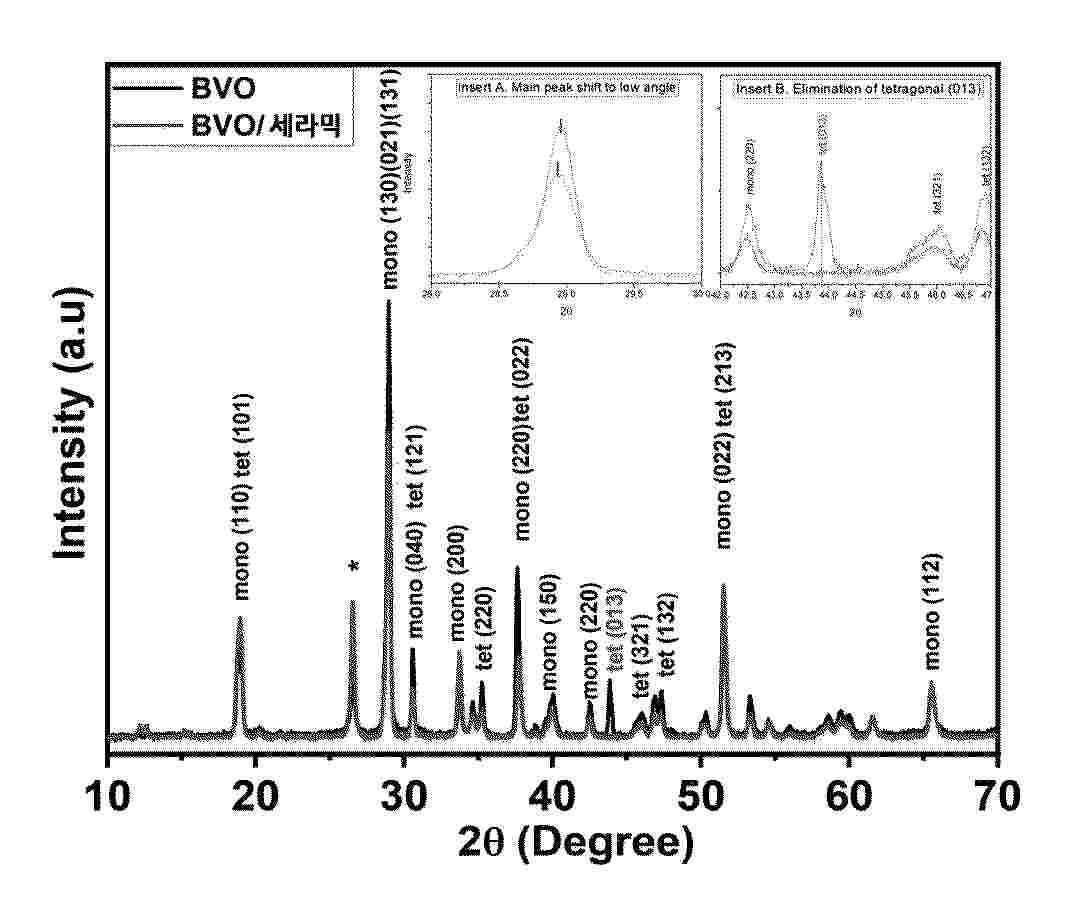
본 발명은 우수한 성능을 지닌 광활성 재료용 복합체, 이를 포함하는 산소 발생 반응용 광전극, 및 이의 제조방법 등에 관한 것으로, 본 발명의 여러 구현예를 통하여 궁극적으로 우수한 성능으로 광전기화학적 물 분해를 통한 녹색 수소 생산을 달성할 수 있다.
Resumen de: US20260035242A1
A hydrogen generation system with controlled water distribution is disclosed. The system comprises a reaction chamber containing a hydrogen-producing fuel, a liquid distribution mechanism, and a control system. The liquid distribution mechanism includes a rotating arm with liquid injection ports that move vertically through the fuel chamber. This allows for precise and efficient liquid delivery to unreacted fuel, optimizing hydrogen production. A proprietary fuel blend utilizes chemicals that store significant amounts of hydrogen in a solid-state form. A feature of the device is the arm's controlled vertical movement, achieved through a screw mechanism that adjusts the arm's height as it rotates, creating a spiral liquid distribution pattern. The control system regulates liquid injection rates, arm rotation speed, and vertical movement to optimize hydrogen production based on demand. The system can also operate at low pressures and be scaled to different sizes in a safer, more efficient, on-demand manner.
Resumen de: JP2026021217A
【課題】水素の製造効率が良く、水酸化マグネシウムの産業廃棄物を産出しない、水から水素を製造する方法を提供する。【解決手段】水素化マグネシウムとクエン酸やグルコン酸などのハイドロオキシカルボン酸を水酸化マグネシウムの1.2モル比倍以上加えた塩化マグネシウム水溶液から製造したクロロマグネシウムプラズマで水から水素を製造する方法である。【選択図】なし
Resumen de: JP2026020879A
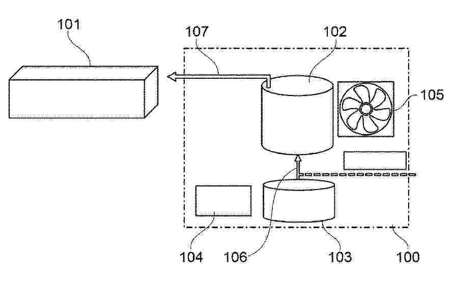
【課題】電極性能に関連する状態のばらつきが少ない水電解用電極を製造する観点から有利な水電解用電極の製造方法を提供する。【解決手段】水電解用電極の製造方法は、下記(I)及び(II)を含んでいる。(I)少なくとも1つの導電性基材21上に水電解用電極を形成させるための原料溶液L1を少なくとも1つの導電性基材21が配設された容器11を経由して循環させる。(II)容器11の内部における原料溶液L1の流れの向きを反転させる。【選択図】図1
Resumen de: JP2026020880A
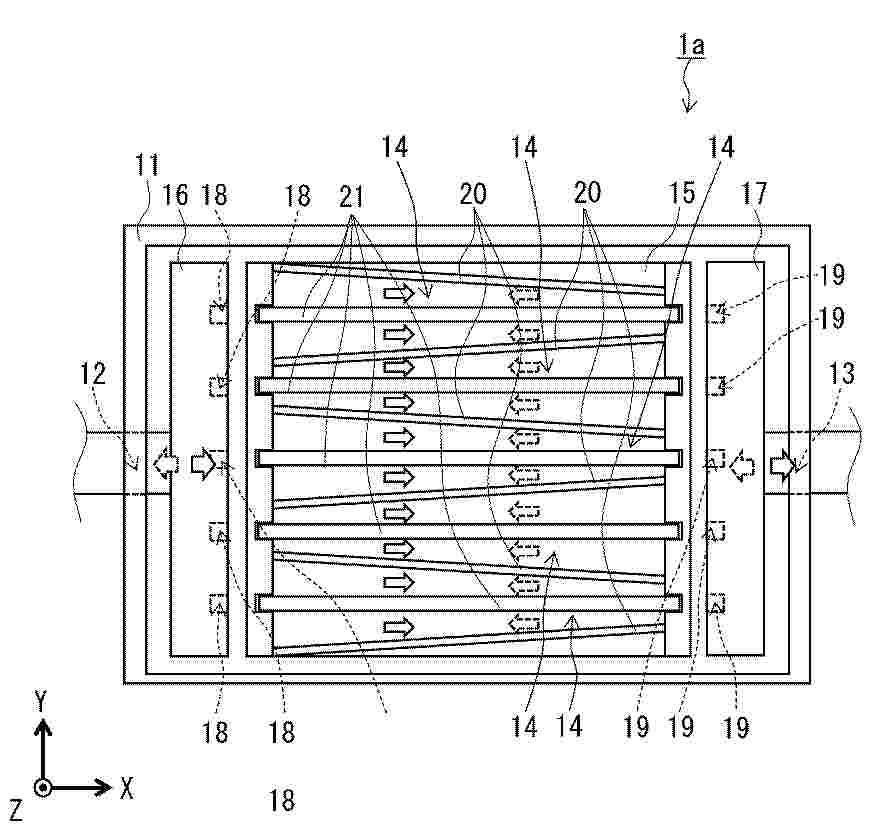
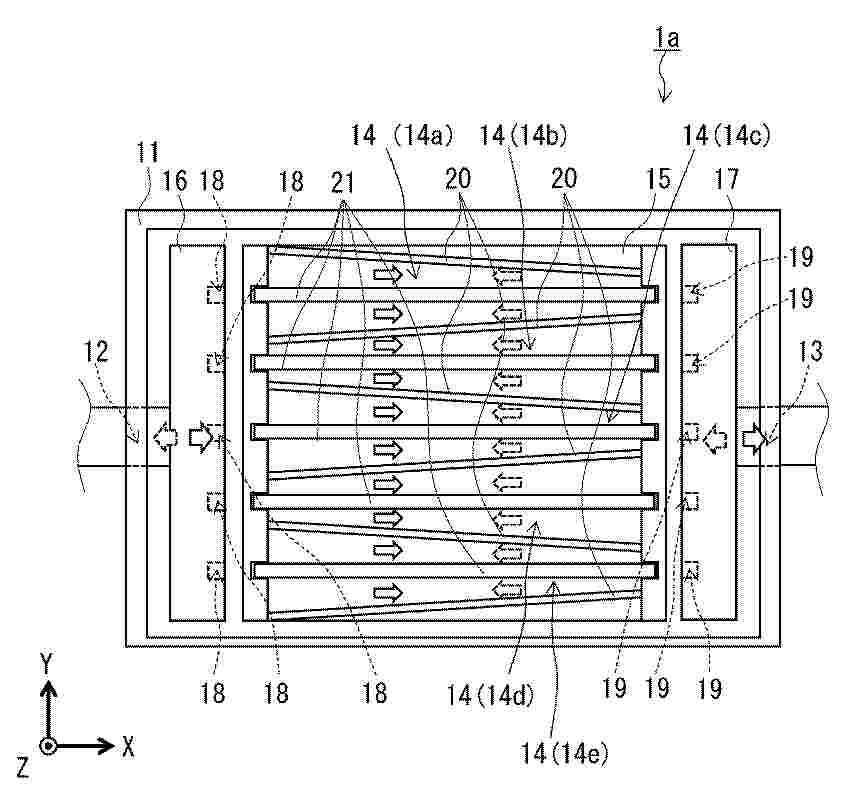
【課題】少なくとも特定の箇所において電極性能に関連する状態のばらつきが少ない水電解用電極を製造する観点から有利な水電解用電極の製造方法を提供する。【解決手段】水電解用電極の製造方法は、下記(I)、(II)、及び(III)を含んでいる。(I)少なくとも1つの導電性基材21上に水電解用電極を形成させるための原料溶液L1を少なくとも1つの導電性基材21が配設された容器11を経由して循環させる。(II)原料溶液L1が少なくとも1つの流路14を通過する。(III)原料溶液L1の流れの下流における流路14の流路断面積が原料溶液L1の流れの上流における流路14の流路断面積よりも小さい状態で原料溶液L1の流れを生じさせる。【選択図】図1
Resumen de: JP2026020857A
【課題】Irを含有しなくても、十分な触媒性能および十分な耐久性を有する新規な水電解陽極触媒を提供する。【解決手段】第四周期以上第六周期以下の第IV、V、VI族元素および第二周期以上第六周期以下のXIV族元素からなる群から選択される少なくとも一種の元素、を含む炭化物、窒化物、およびホウ化物からなる群から選択される少なくとも一種の化合物、を含む水電解陽極触媒。【選択図】なし
Resumen de: JP2026020881A
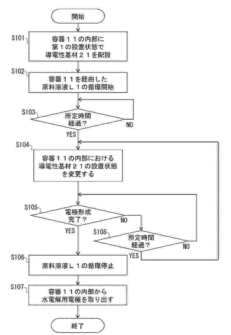
【課題】従来よりも電極性能に関連する状態のばらつきが少ない水電解用電極を製造する観点から有利な水電解用電極の製造方法を提供する。【解決手段】水電解用電極の製造方法は、第1の設置状態及び第2の設置状態において少なくとも1つの導電性基材21上に水電解用電極を形成させるための原料溶液L1を少なくとも1つの導電性基材21が配置された容器11を経由して循環させる。第2の設置状態における少なくとも1つの導電性基材21の向きは、第1の設置状態における少なくとも1つの導電性基材21を、所定の直線を回転軸として半回転させたときの少なくとも1つの導電性基材21の向きと一致する。所定の直線は、少なくとも1つの導電性基材21の主面上の直線又は少なくとも1つの導電性基材の主面と交差する直線である。【選択図】図5
Resumen de: CN121496458A
本发明属于电催化二氧化碳还原反应技术领域,具体公开了Ni‑Co双单原子催化剂及其制备方法和应用,催化剂包括碳载体,原子级分散的Ni单原子,以Ni‑N4构型锚定于碳载体;原子级分散的Co单原子,以Co‑N4构型锚定于碳载体,催化剂中无金属‑金属键。本发明采用上述的Ni‑Co双单原子催化剂及其制备方法和应用,通过Ni‑N4和Co‑N4双活性位点分别独立调控CO2‑to‑CO转化和析氢反应(HER),实现CO/H2比例在0.3:1‑2.5:1范围内精确可调;利用Ni单原子位点调控界面水氢键网络刚性,平衡CO2和H2O的活化动力学,抑制工业级电流密度下的副反应。
Resumen de: CN121490765A
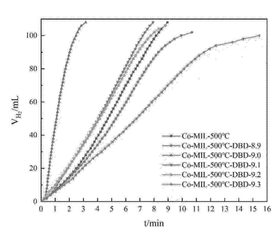
本发明适用于制氢技术领域,提供了一种MOF衍生多层碳材料催化剂的制备方法及其应用,所述催化剂以钴基MOF为前驱体,经高温焙烧后,再通过特定条件的DBD等离子体处理制得。DBD处理能有效减小催化剂粒径,增加活性位点暴露,提高钴物种分散度。将所得催化剂用于氨硼烷甲醇分解制氢反应,在温和条件下即可实现高效产氢,其催化活性与部分贵金属催化剂相当。本发明制备工艺简单、能耗低、环境友好,为非贵金属催化剂的开发及氨硼烷储氢材料的应用提供了新途径。
Resumen de: CN121496445A
本发明涉及电解水制氢的技术领域,提供一种PEM电解水的阳极催化剂浆料的制备方法及浆料及催化层,所述制备方法包括:S1、将阳极催化剂、第一离聚物、第一溶剂混合,分散,得到第一催化剂浆料;S2、将消氢催化剂、第二离聚物、第二溶剂混合,分散,得到第二催化剂浆料;所述消氢催化剂为碳载贵金属催化剂;S3、将第一催化剂浆料和第二催化剂浆料混合,进行均质化处理,得到阳极催化剂浆料。优点:通过消氢添加剂的添加、浆料制备工艺步骤等的配合设置,同时实现提高均匀性、改善传质和降低氧中氢的效果,提升了膜电极性能和安全性。
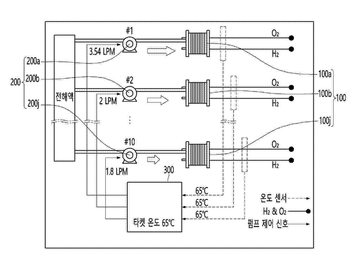
Resumen de: KR20260018245A
본 발명의 일 태양에 따르면, 수전해 스택에 공급되는 전해액의 유량을 개별 제어하기 위한 수전해 시스템으로서, 복수의 수전해 스택, 상기 복수의 수전해 스택과 일대일 대응으로 연결되어 전해액을 공급하는 복수의 전해액 공급 펌프, 및 상기 복수의 수전해 스택으로부터 배출되는 수소 가스 또는 산소 가스의 온도와 상기 복수의 수전해 스택에 대하여 설정되는 타겟 온도를 참조하여 상기 복수의 전해액 공급 펌프의 유량을 개별 제어하는 유량 제어부를 포함하는 수전해 시스템이 제공된다.
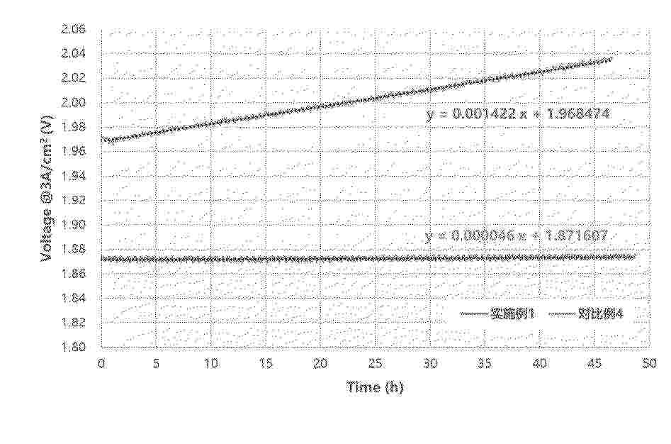
Resumen de: KR20260018302A
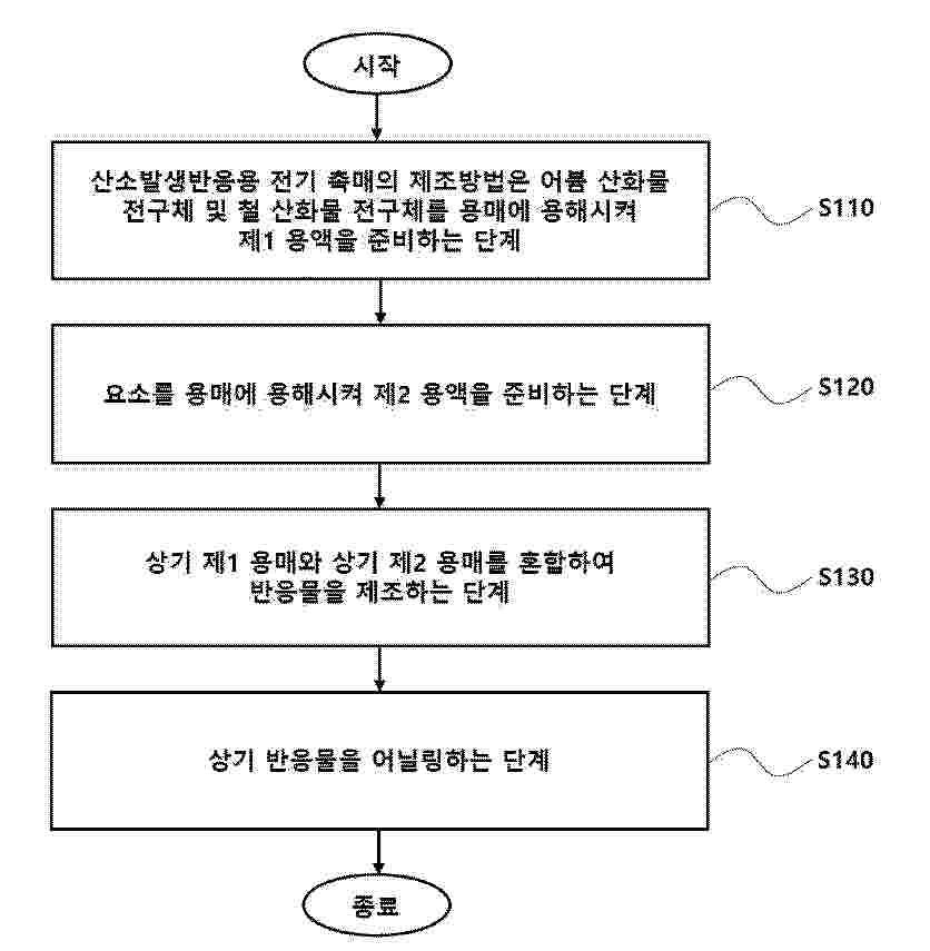
산소발생반응용 전기 촉매를 개시한다. 어븀 산화물 나노 클러스터(nano cluster); 및 상기 어븀 산화물 나노 클러스터 상에 배치되어 상기 어븀 산화물 나노 클러스터와 이종계면을 형성하는 철 산화물 나노 입자를 포함한다.
Resumen de: CN120882907A
A system and method for generating hydrogen from a liquid source comprising water is disclosed. The system comprises: a high fluid velocity electrolysis cell comprising an inlet and an outlet, the inlet of the high fluid velocity electrolysis cell being fluidly connected to a liquid source; and a gas fractionation system fluidly connected to the outlet of the high fluid velocity electrolysis cell.
Resumen de: CN121481107A
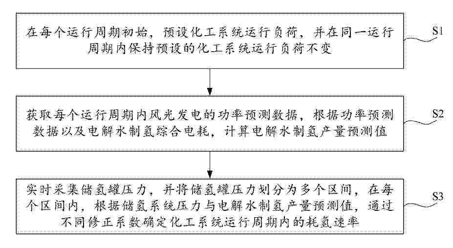
本发明涉及再生能源利用与绿色化工耦合技术领域,公开了可再生能源电解水制氢耦合绿色化工的运行方法及系统,运行方法包括:在每个运行周期初始,预设化工系统运行负荷,并在同一运行周期内保持预设的化工系统运行负荷不变;获取每个运行周期内风光发电的功率预测数据,根据功率预测数据以及电解水制氢综合电耗,计算电解水制氢产量预测值;实时采集储氢罐压力,并将储氢罐压力划分为多个区间,在每个区间内,根据储氢系统压力与电解水制氢产量预测值,通过不同修正系数确定化工系统运行周期内的耗氢速率。结合储氢情况及风、光电功率预测,设置下一时间周期内的化工稳定运行负荷,提升化工系统运行的稳定性,降低变负荷操作频率。
Resumen de: JP2026020096A
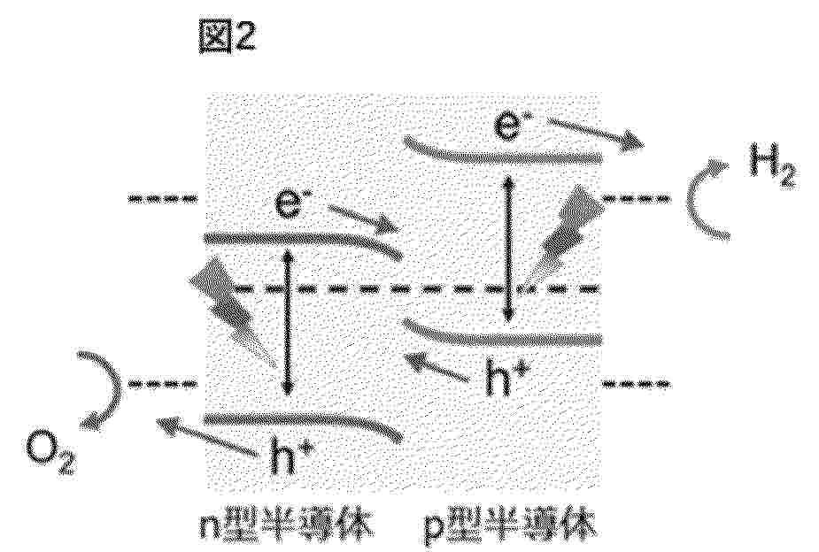
【課題】p型半導体とn型半導体とを組み合わせた接合体であって、効率よく酸化還元反応を起こす光触媒として使用できる接合体の提供。【解決手段】Cu系のp型酸化物半導体と、M1Fe2O4又はM2WO4(M1およびM2は、それぞれ独立して、金属元素)であるn型酸化物半導体とを接合した、接合体。【選択図】図2
Resumen de: CN121472864A
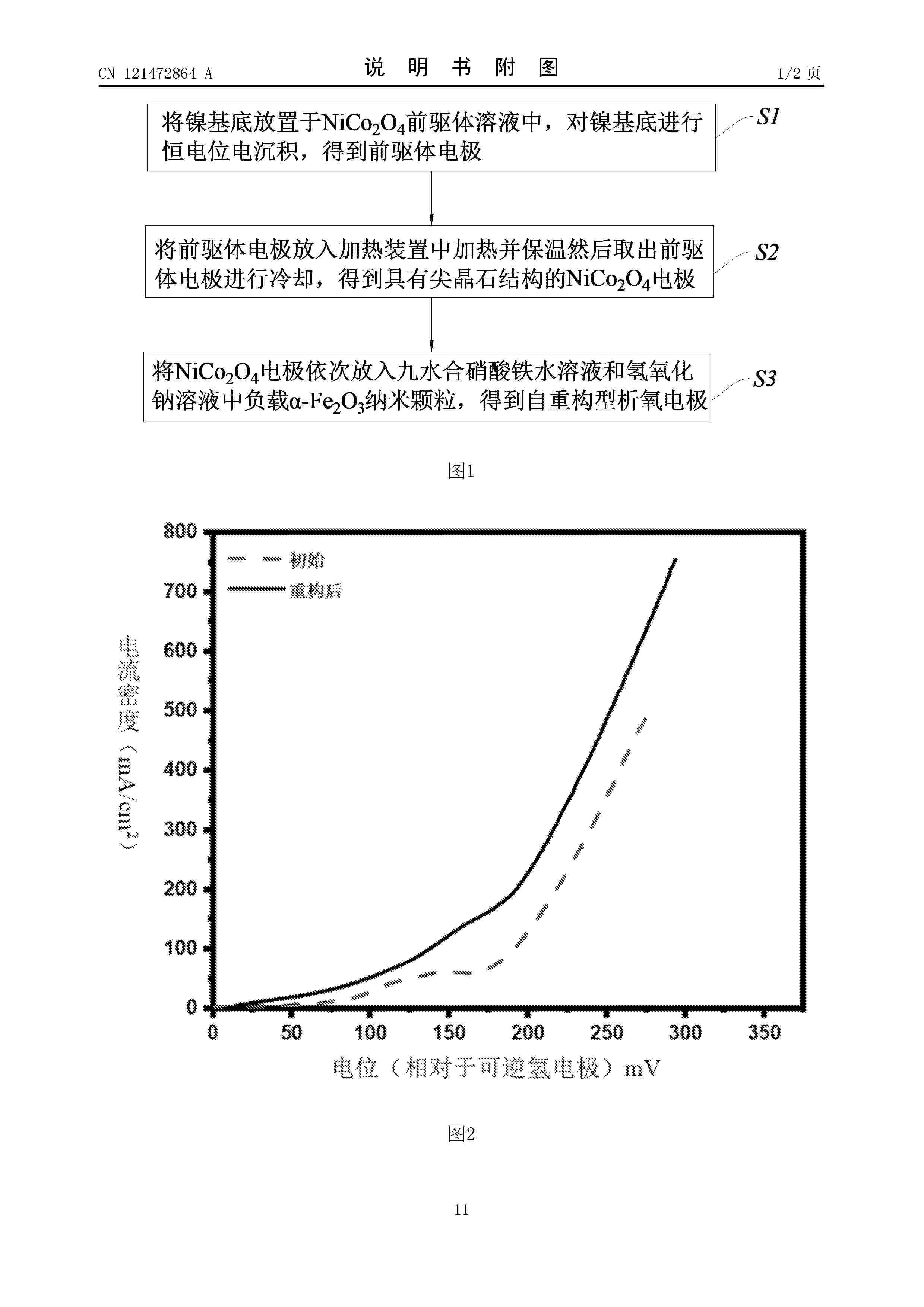
本发明公开了一种自重构型析氧电极、制备方法及应用,该制备方法包括将镍基底作为工作电极,铂片作为对电极,饱和甘汞电极作为参比电极放置于NiCo2O4前驱体溶液中,对镍基底进行恒电位电沉积,得到表面具有Ni‑Co LDH前驱体的前驱体电极;将前驱体电极放入加热装置中加热并保温,然后取出前驱体电极进行冷却,得到具有尖晶石结构的NiCo2O4电极;将NiCo2O4电极依次放入九水合硝酸铁水溶液和氢氧化钠溶液中,使用连续离子层吸附反应法在NiCo2O4电极的表面负载α‑Fe2O3纳米颗粒,得到自重构型析氧电极。该自重构型析氧电极的制备方法在镍基底上构建由尖晶石结构的NiCo2O4和α‑Fe2O3组成的复合催化层,能适应功率波动。
Resumen de: CN121472926A
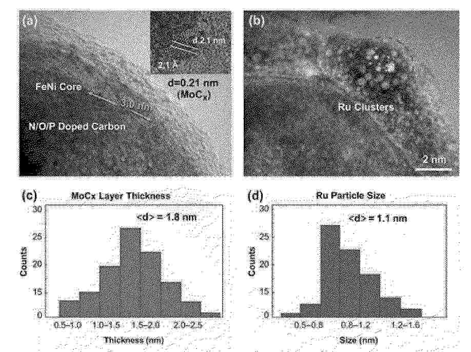
本发明公开了一种木质素多金属有序碳化界面四元电触媒,主要由FeNi合金纳米核、MoCx 渐变界面层、Ru超小金属簇和N/O/P 共掺杂木质素派生碳壳构成;MoCx 渐变界面层紧密包覆于 FeNi合金纳米核表面,Ru超小金属簇分布在MoCx 渐变界面层和N/O/P 共掺杂木质素派生碳壳之间,N/O/P 共掺杂木质素派生碳壳包围在最外层。据此,还建立了相应制备方法。本发明四元电触媒可以应用于高流密整体水分解,并用来制备电极或碱性整体水分解电解槽,为木质素等生物质资源在高流密电解水领域的高价值利用提供了一条新路径。
Nº publicación: CN121472894A 06/02/2026
Solicitante:
佛山仙湖实验室
Resumen de: CN121472894A
本发明公开了一种PEM电解槽的集成式密封结构及PEM电解槽,包括极板组件、膜电极组件和集成式密封体,极板组件包括两块双极板,双极板的两侧表面均设置有至少一个环形密封槽;集成式密封体夹装于两块双极板之间,且沿膜电极组件的四周密封设置,集成式密封体的横截面包括扁平状的密封主体,密封主体的其中一侧表面设有至少一个第一线密封部和至少一个第一面密封部,另外一侧设有至少一个第二线密封部和至少一个第二面密封部,第一线密封部和第二线密封部分别与对应的环形密封槽密封抵接,第一面密封部和第二面密封部分别与两块双极板的表面密封抵接。本发明结合了线密封+面密封,增强了高压下的密封力,降低了装夹力,有效防止侧移风险。
 BOPI
BOPI
 Sede Electrónica