Si deseas distinguir tus productos, servicios o ambos de los de otra empresa, es posible que necesites una marca o nombre comercial. Descubre qué son, en qué consiste su procedimiento de registro y qué implica.

Información sobre los plazos de presentación de solicitudes de transformación de marcas de la Unión Europea en marca nacional española. Más información


Si tienes un nuevo dispositivo, producto o procedimiento que resuelva un problema técnico o tenga una ventaja práctica, existen distintas formas de protegerlo en España y en otros países. Descubre cómo hacerlo.

¿Tu innovación reside en la estética, la ornamentación o la apariencia de tu producto? Protégela mediante un diseño industrial. Descubre qué derechos confiere el registro y cómo realizar la tramitación.

Las indicaciones geográficas protegen el nombre de un producto originario de una zona geográfica, a la cual le debe una determinada calidad, reputación u otra característica. Descubre qué son, en qué consiste su procedimiento de registro y qué beneficios conceden.

Las patentes publicadas en todo el mundo son una valiosa fuente de información científica, técnica y comercial.

Si eres emprendedor/a o una empresa y quieres potenciar y mejorar la rentabilidad de tu negocio protegiendo de forma adecuada los activos intangibles de tu organización, en este espacio encontrarás lo necesario.


 120
resultados
120
resultados
 Última actualización
05/04/2026 [06:59:00]
Última actualización
05/04/2026 [06:59:00]


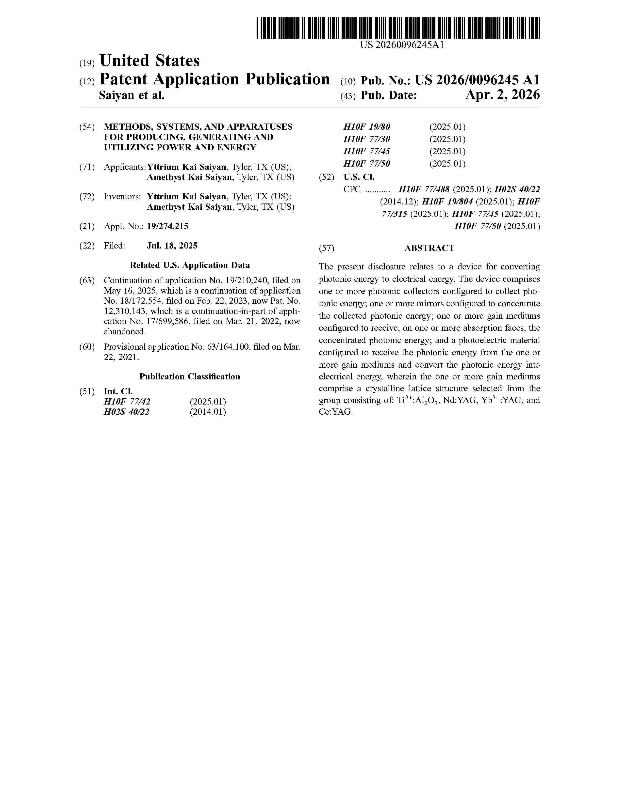
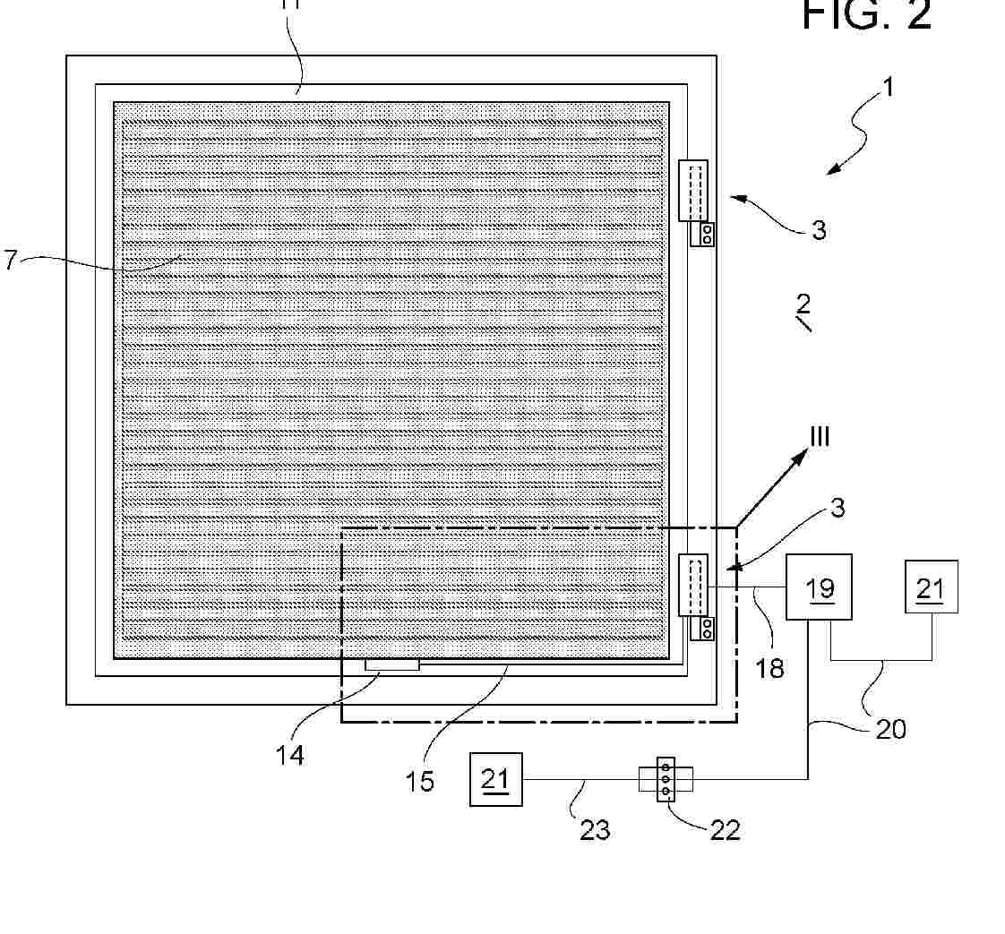
Resumen de: US20260096245A1
The present disclosure relates to a device for converting photonic energy to electrical energy. The device comprises one or more photonic collectors configured to collect photonic energy; one or more mirrors configured to concentrate the collected photonic energy; one or more gain mediums configured to receive, on one or more absorption faces, the concentrated photonic energy; and a photoelectric material configured to receive the photonic energy from the one or more gain mediums and convert the photonic energy into electrical energy, wherein the one or more gain mediums comprise a crystalline lattice structure selected from the group consisting of: Ti3+:Al2O3, Nd:YAG, Yb3+:YAG, and Ce:YAG.

Resumen de: AU2024344953A1
A solar collecting fencing system is provided, comprising a fence panel assembly with a metal sheet formed as a single piece. The metal sheet is shaped to define contoured sections, each having a major and minor portion. Elongate solar panels are affixed to the major portions to facilitate solar energy collection. The system is designed for use as a functional fence while maximising solar energy capture. Electrical wiring is connected between the solar panels, and a rail may be installed to protect the wiring. The system is suitable for installation in various configurations to optimise solar exposure.
Resumen de: US20260092422A1
An anti-tip ground pile for a solar tracking system includes an elongate tube having a central longitudinal axis, one or more blades formed along the tube for engaging with a ground in which the ground pile is implanted, and a stabilizing panel rotatably engaged with the tube such that the panel is continuously rotatable around the entire tube. The stabilizing panel providing support to the tube to help prevent the tube from tipping over in soil in which the tube is implanted.
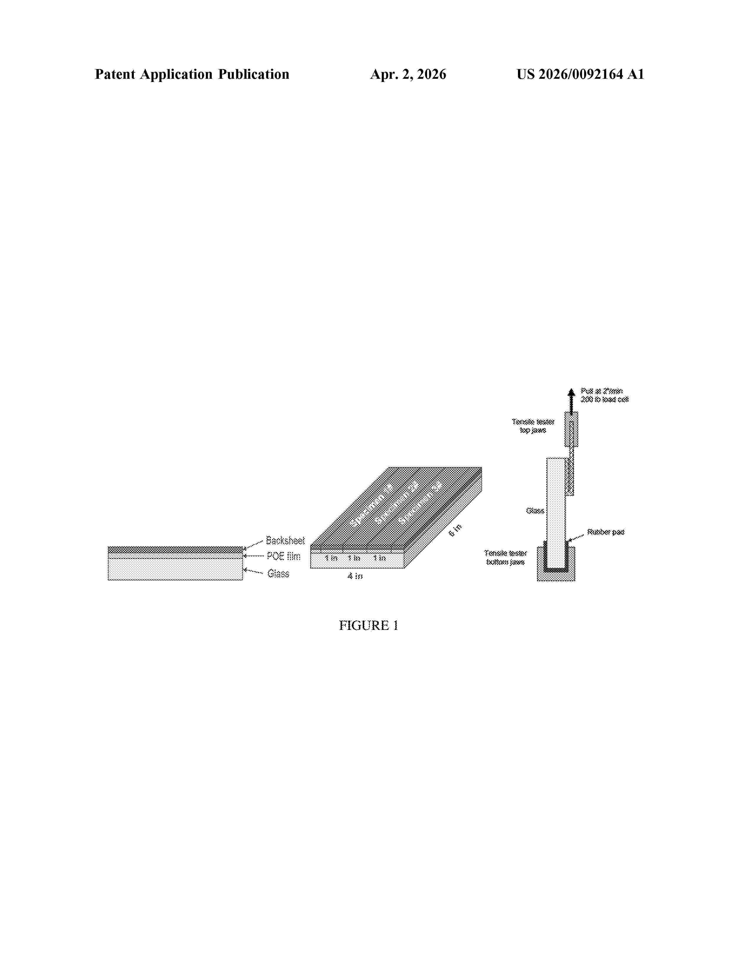
Resumen de: US20260092164A1
A composition comprising the following: a) an ethylene/alpha-olefin/interpolymer;b) a peroxide;c) a “Si-containing compound” selected from the following i) through v): i)where each R is independently selected from a C1-C3 alkyl, and n is from 1 to 16; ii)where each R is independently methyl or ethyl, and n is from 1 to 18; iii)where each R is independently methyl or ethyl; iv) a vinyl oligomeric siloxane; or v) any combination of i) through iv).
Resumen de: AU2024331510A1
This disclosure is related to materials with highly stable and reversible water sorption and retention properties, as well as formulations and methods for their manufacture and uses. Composite materials of the present disclosure can avoid weeping or leakage of liquid water at wide ranges in ambient relative humidities so as to be suitable for a variety of applications including thermal management, thermal energy storage, atmospheric water generation and dehumidification systems. Composites disclosed herein can comprise an ionomeric material and in some embodiments, a hygroscopic or deliquescent salt. Furthermore, composites disclosed herein can also include a water vapor permeable or support polymer material providing support for reversible expansion or volume changes during water vapor sorption/desorption cycling via porous and/or elastic character, thereby avoiding mechanical restriction that could cause weeping or leakage of liquid water.
Resumen de: AU2024327333A1
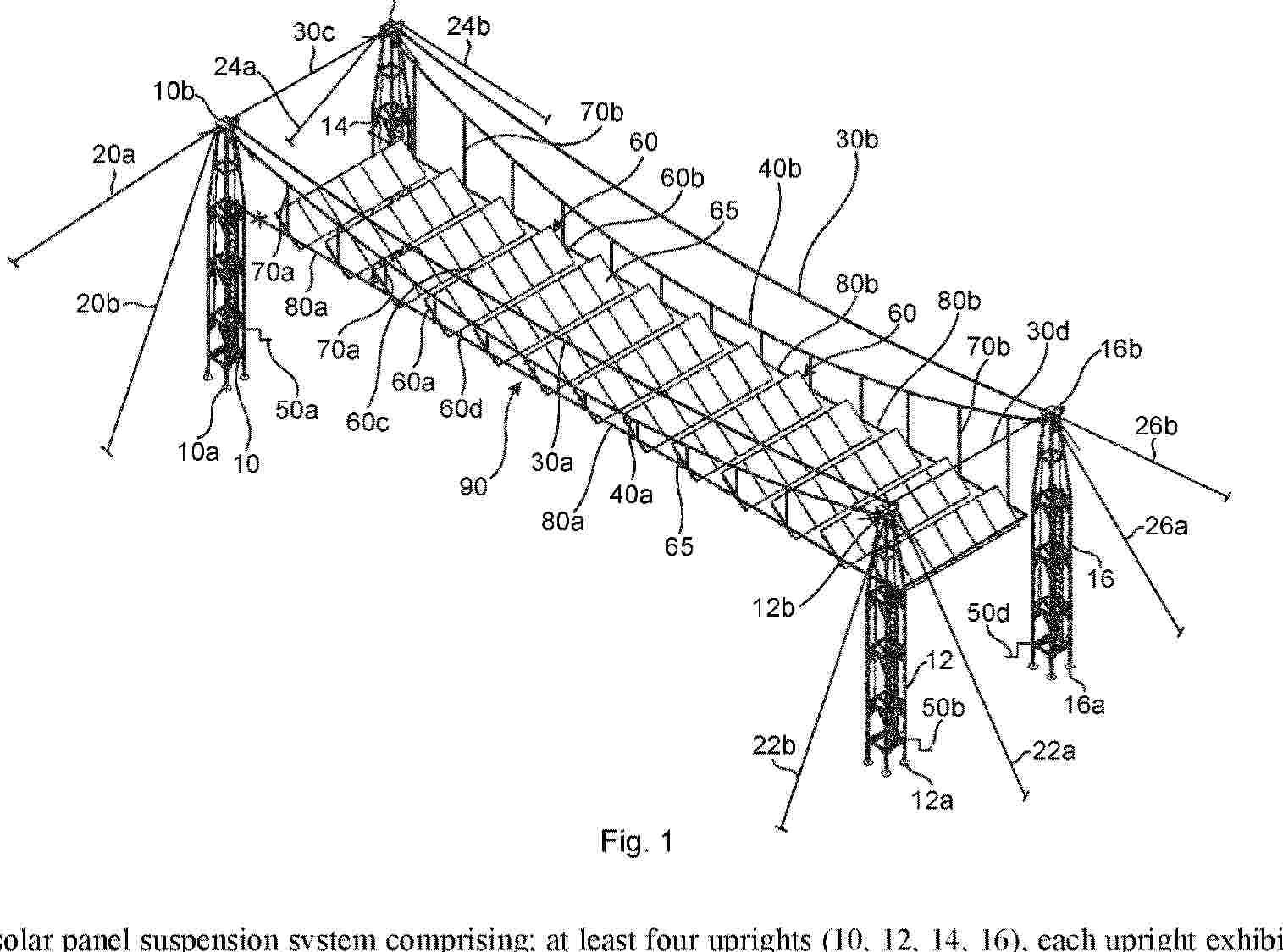
A solar panel suspension system comprising; at least four uprights (10, 12, 14, 16), each upright exhibiting a bottom end (10a, 12a, 14a, 16a) and a top end (10b, 12b, 14b, 16b), said at least four uprights being arrangeable in pairs, wherein each pair comprises two uprights aligned in a first direction and wherein the pairs are arranged in parallel, side by side in a second direction which is perpendicular to the first direction. Supporting wires (20a 20b, 22a, 22b, 24a, 24b, 26a, 26b, 30a 30b, 30c, 30d) are arranged to support the uprights by supportingly connecting each upright to the ground and to at least two neighbouring uprights. At least two first suspension wires (40a, 40b) are arranged to extend in a first direction between the top end of two uprights in a respective pair of uprights. The system further comprises a plurality of rectangular planar support frames (60), which are arranged to be supportingly connected to two first suspension wires (40a, 40b). A hoisting arrangement (50a, 50b, 50d) is arranged to extend and retract each first suspension wire (40a, 40b) from the top end of both uprights (10, 12, 14, 16) in each pair of uprights. A method of erection such a system is also described.
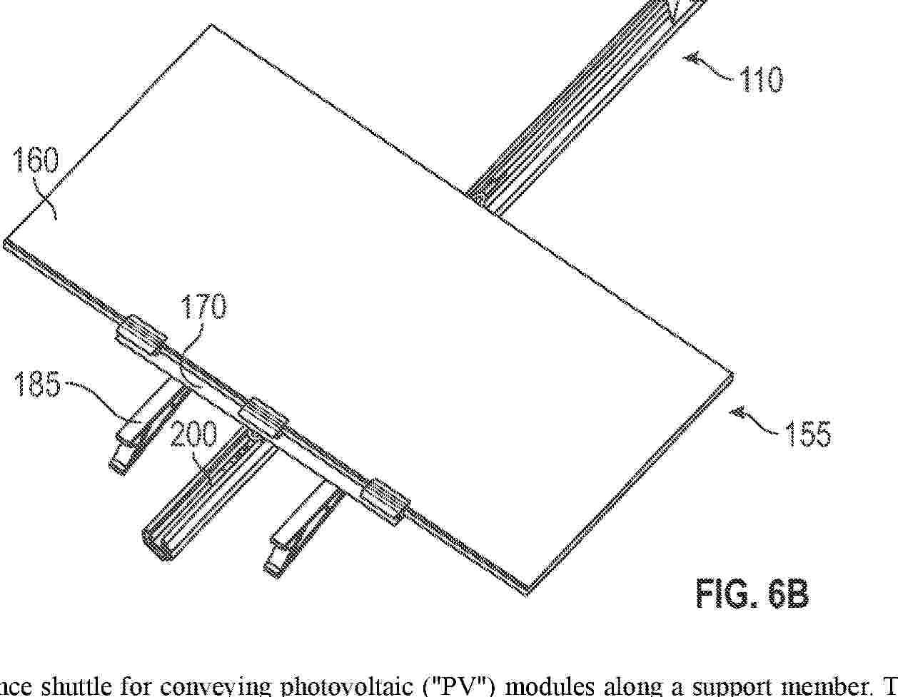
Resumen de: AU2024344275A1
A conveyance shuttle for conveying photovoltaic ("PV") modules along a support member. The conveyance shuttle comprises a receptacle for receiving a member of a PV module or a PV module support panel, wherein the conveyance shuttle, when coordinated with the shuttle coordinating feature, is capable of conveying the PV module or PV module support panel along a length of the support member.
Resumen de: US20260096240A1
Provided in one embodiment is a method of making, comprising: exposing a raw material having a first viscosity to a first pressure and a first temperature such that the raw material after the exposure has a second viscosity, wherein the raw material comprises particles comprising at least one electrically conductive material, and wherein the second viscosity is sufficiently low for the raw material to be adapted for a hydrodynamic cavitation process; and subjecting the raw material having the second viscosity to the hydrodynamic cavitation process to make a product material having a third viscosity. Apparatus employed to apply the method and the exemplary compositions made in accordance with the method are also provided.
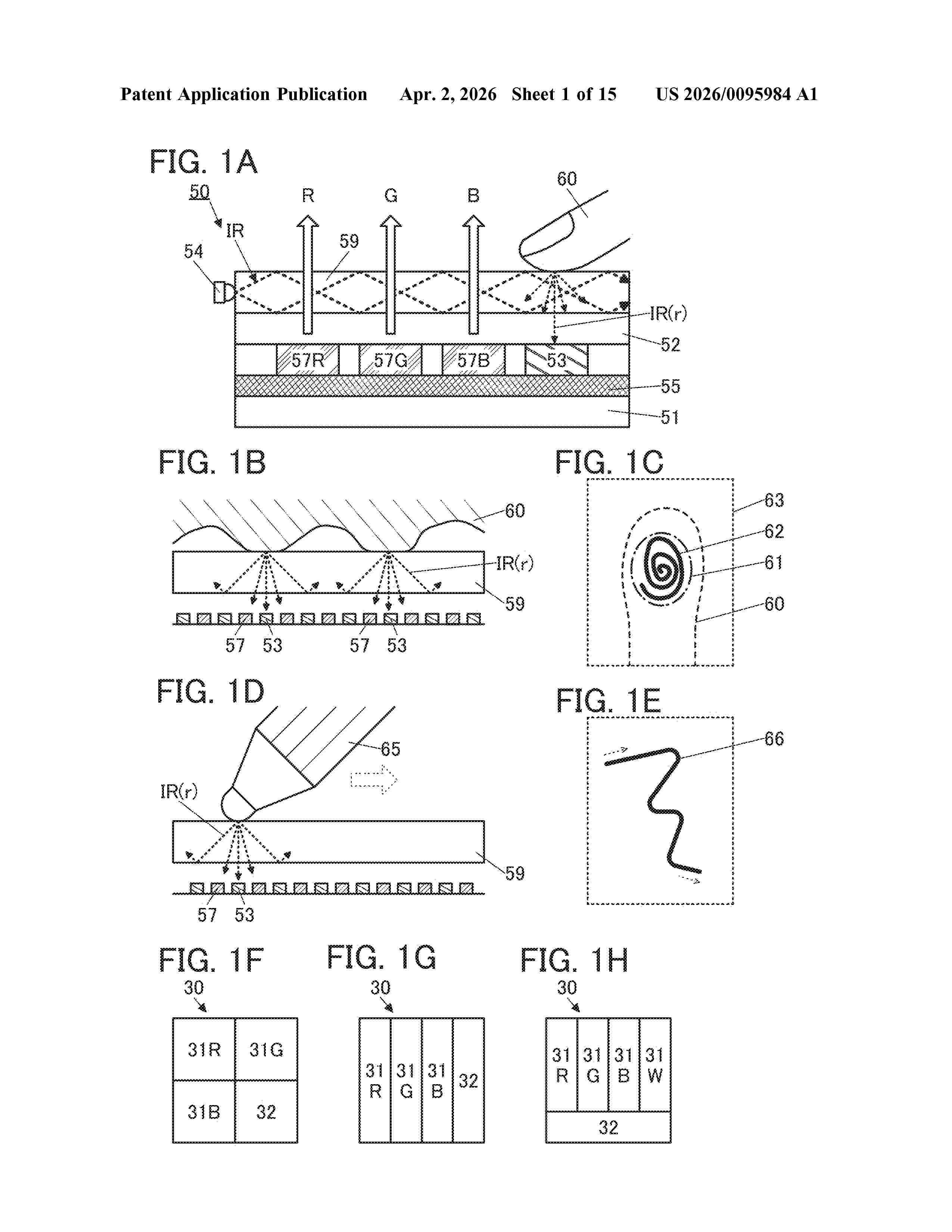
Resumen de: US20260095984A1
A display device having a photosensing function is provided. A display device having a biometric authentication function typified by fingerprint authentication is provided. A display device having both a touch panel function and a biometric authentication function is provided. The display device includes a first substrate, a light guide plate, a first light-emitting element, a second light-emitting element, and a light-receiving element. The first substrate and the light guide plate are provided to face each other. The first light-emitting element and the light-receiving element are provided between the first substrate and the light guide plate. The first light-emitting element has a function of emitting first light through the light guide plate. The second light-emitting element has a function of emitting second light to a side surface of the light guide plate. The light-receiving element has a function of receiving the second light and converting the second light into an electric signal. The first light includes visible light, and the second light includes infrared light.
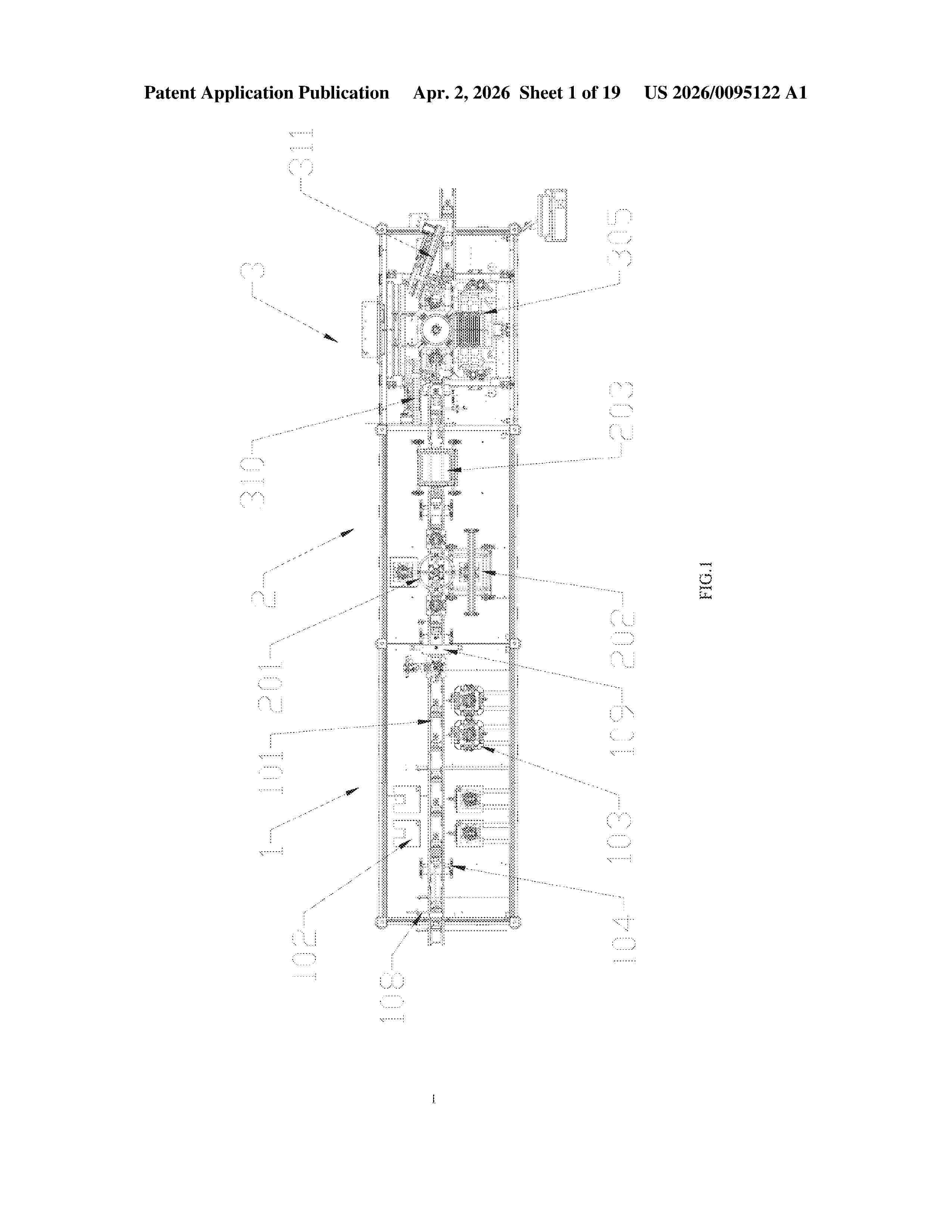
Resumen de: US20260095122A1
The present invention discloses a solar silicon wafer inspection all-in-one machine, comprising a front-end conveying rail, an AOI detection mechanism and an IV detection mechanism, wherein the AOI detection mechanism is positioned between the front-end conveying rail and the IV detection mechanism; at least one segment of silicon wafer conveying rail is arranged on the front-end conveying rail; the AOI detection mechanism includes a four-position turntable, a back AOI detection instrument assembly, a front AOI detection instrument assembly and an AOI detection conveying rail; the IV detection mechanism includes a working platform, an indexing disc assembly and at least one detection mechanism. This solar silicon wafer inspection all-in-one machine is designed for conveying silicon wafers, successively undergoing AOI inspection and IV inspection. Operating automatically, it precisely connects the probe to the grid lines on the silicon wafers, enhancing inspection efficiency and increasing productivity.
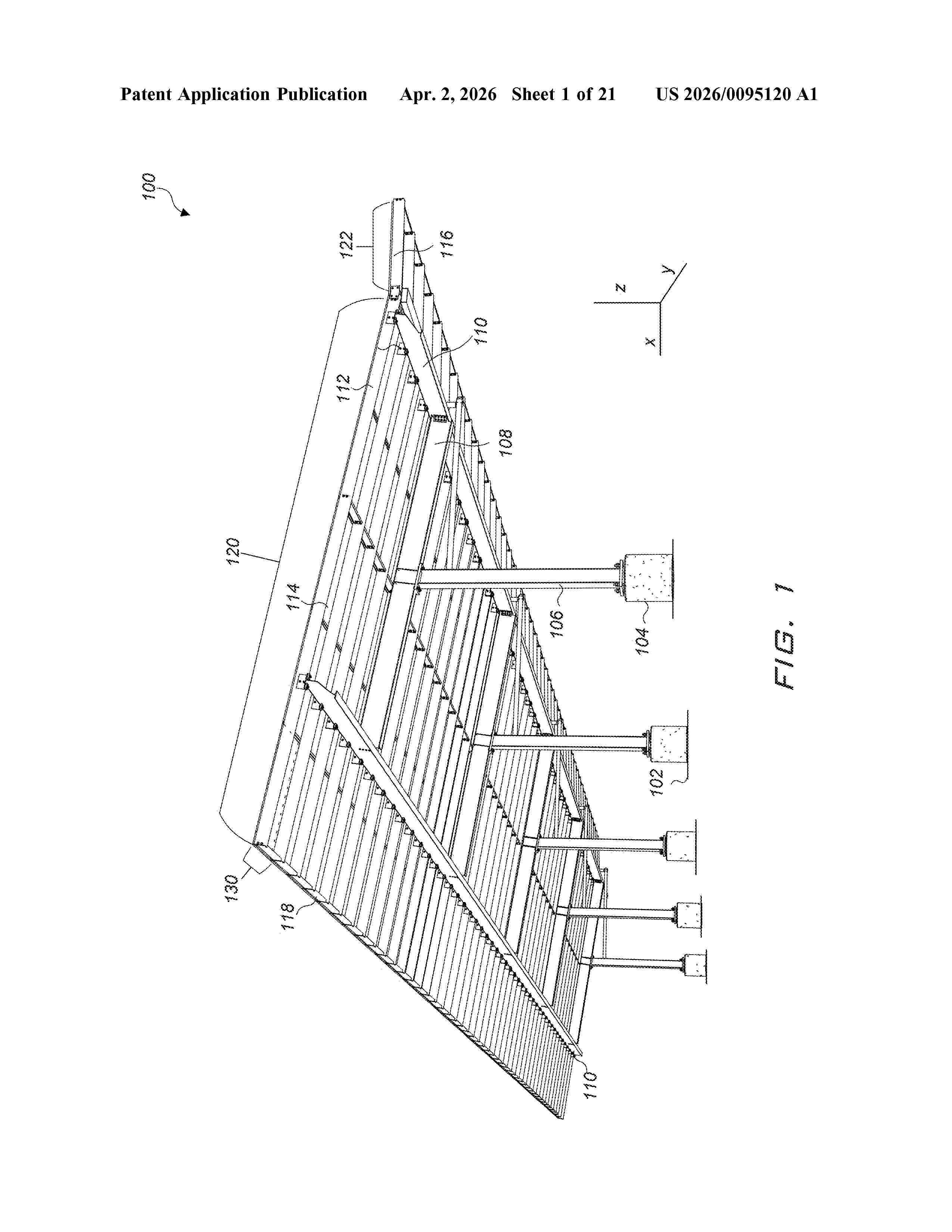
Resumen de: US20260095120A1
Various embodiments of mounting structures for solar photovoltaic (PV) modules and methods for constructing such mounting structures are described. A mounting structure is usable to secure PV modules in portrait orientation or landscape orientation. PV modules are secured to PV module support rails, which may be secured to purlins of a mounting structure using clamps. In some embodiments, self-adhesive grounding patches are used to establish electrical grounding paths in various embodiments of mounting structure.
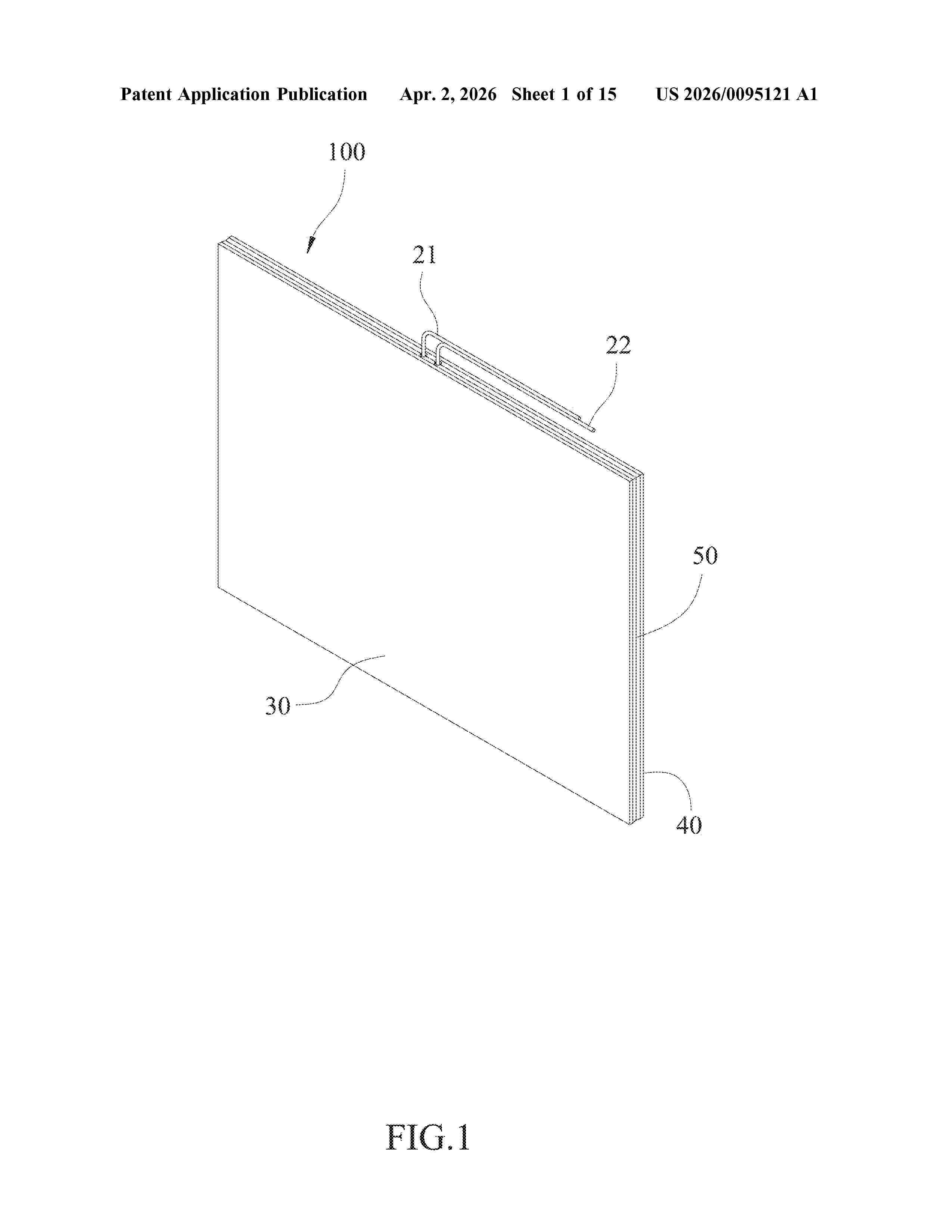
Resumen de: US20260095121A1
A perovskite solar energy generation module includes a solar panel frame, at least one solar panel, a first protective panel, a second protective panel, and a sealing structure. The solar panel is disposed on the solar panel frame. The solar panel frame is engaged between the first protective panel and the second protective panel and is surrounded by the sealing structure. A sealed cavity formed between the first protective panel, the second protective panel, and the sealing structure, preventing the solar panel from being easily oxidized due to environment and hence improving the stability. A construction-shading device is further provided, wherein the perovskite solar energy generation module is disposed in an outer frame. The construction-shading device could have different designs to meet different architectural styles and requirements, thereby bringing renewable energy to daily life and promoting the development of green building.
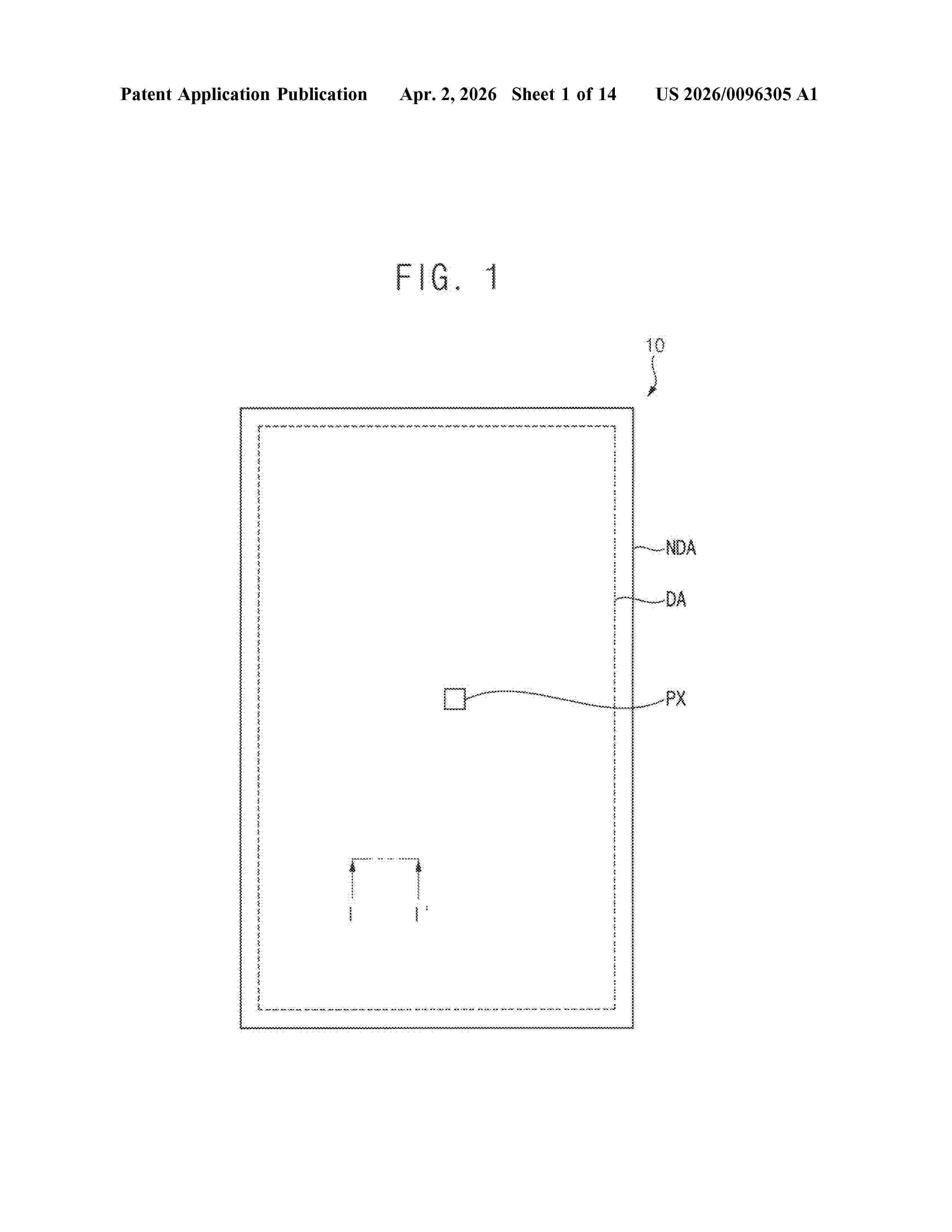
Resumen de: US20260096305A1
A display device includes a transistor disposed on a substrate, an organic layer disposed on the transistor and defining grooves, a first pixel electrode disposed on the organic layer, electrically connected to the transistor, and including a pixel metal layer and a pixel protective layer, the pixel protective layer including at least one of an oxide and a halide and surrounding the pixel metal layer, and a dummy electrode disposed on the organic layer, spaced apart from the transistor, and including a dummy metal layer and a dummy protective layer, the dummy protective layer including at least one of an oxide and a halide and surrounding the dummy metal layer.
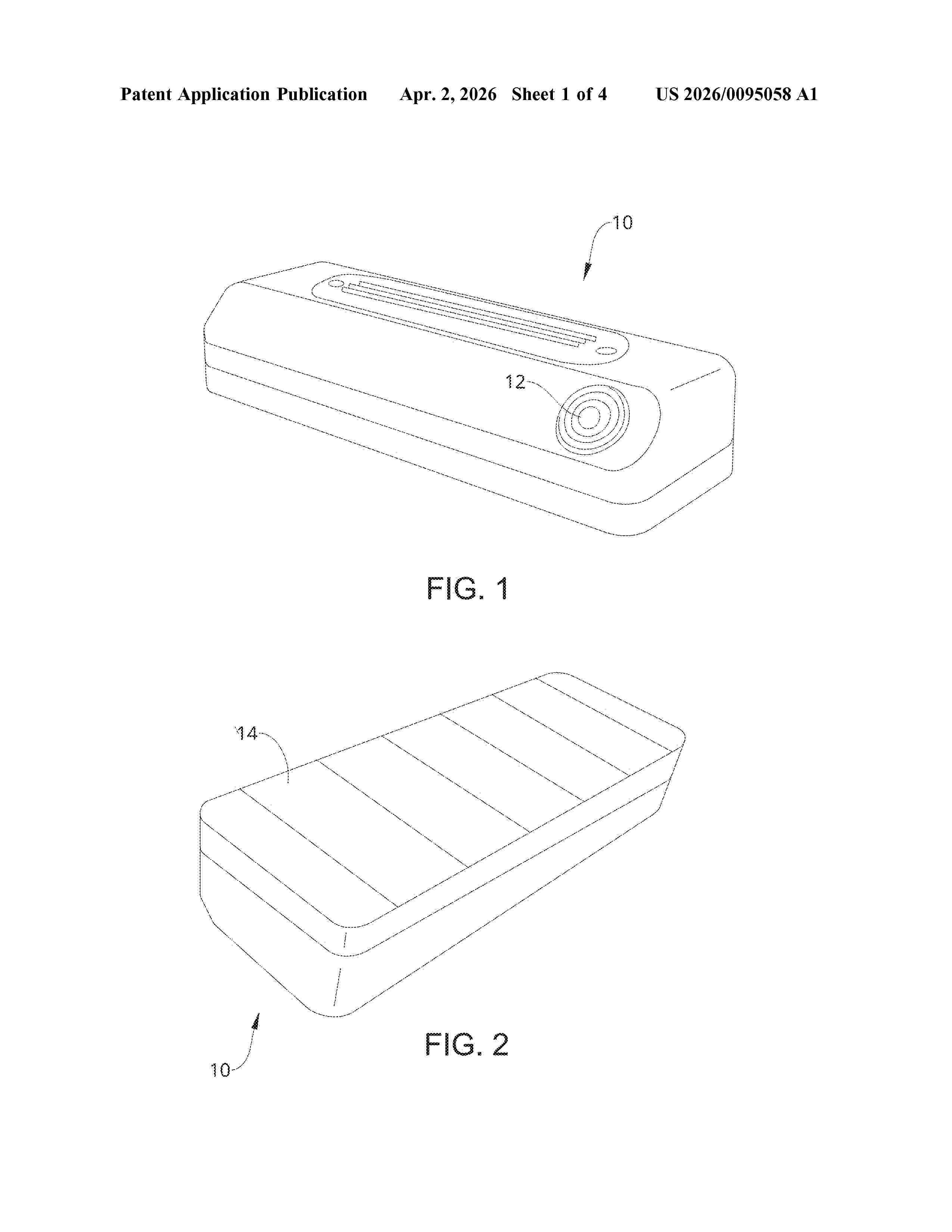
Resumen de: US20260095058A1
A retail environment monitoring device includes an ambient environment sensor; a communications module; a rechargeable battery; a voltage sensor circuit; and an ambient energy harvester. The communications module receives data from the sensor. The battery is connected to the sensor and the communications module. The voltage sensor circuit monitors the charge level of the battery. The ambient energy harvester recharges the battery using ambient energy, such as artificial light.
Resumen de: US20260092676A1
An apparatus includes a first portion. A through-hole extends in a first direction from a first side of the attachment to a second side of the attachment. The through-hole is configured to receive a first fastener. A second portion includes a first vertical wall having an indentation disposed on an inner surface. A second vertical wall has an aperture extending in a second direction perpendicular to the first direction. The aperture is configured to receive a second fastener. A channel is defined between the first vertical wall and the second vertical wall, the channel being sized to receive a standing seam.
Resumen de: US20260095119A1
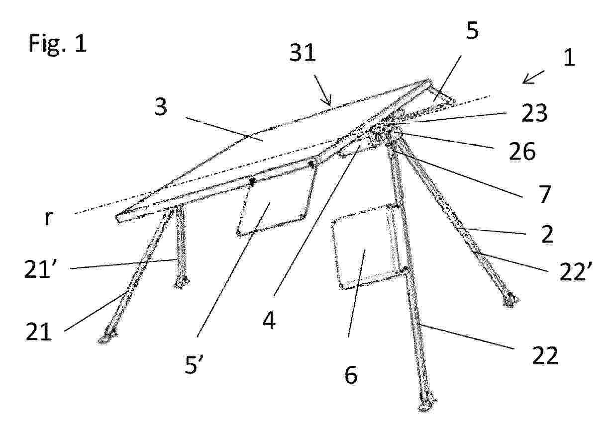
Solar panel fastening system comprising: a pair of upper cables (1) and a pair of lower cables (6), arranged longitudinally and fixed at opposite ends to support posts (2); transverse cables (11) mounted on the upper cables (1) and fastening by means of suspension rods (5) support means (4) of parallel rows (31) of solar panels (3) arranged horizontally, in the transverse direction, below the upper cables. Longitudinally, below the lower cables (6), it comprises braced side arches (7) and oblique braces (8) fixing the sides of the support means (4) of the solar panels (3) with the corresponding side arch (7).
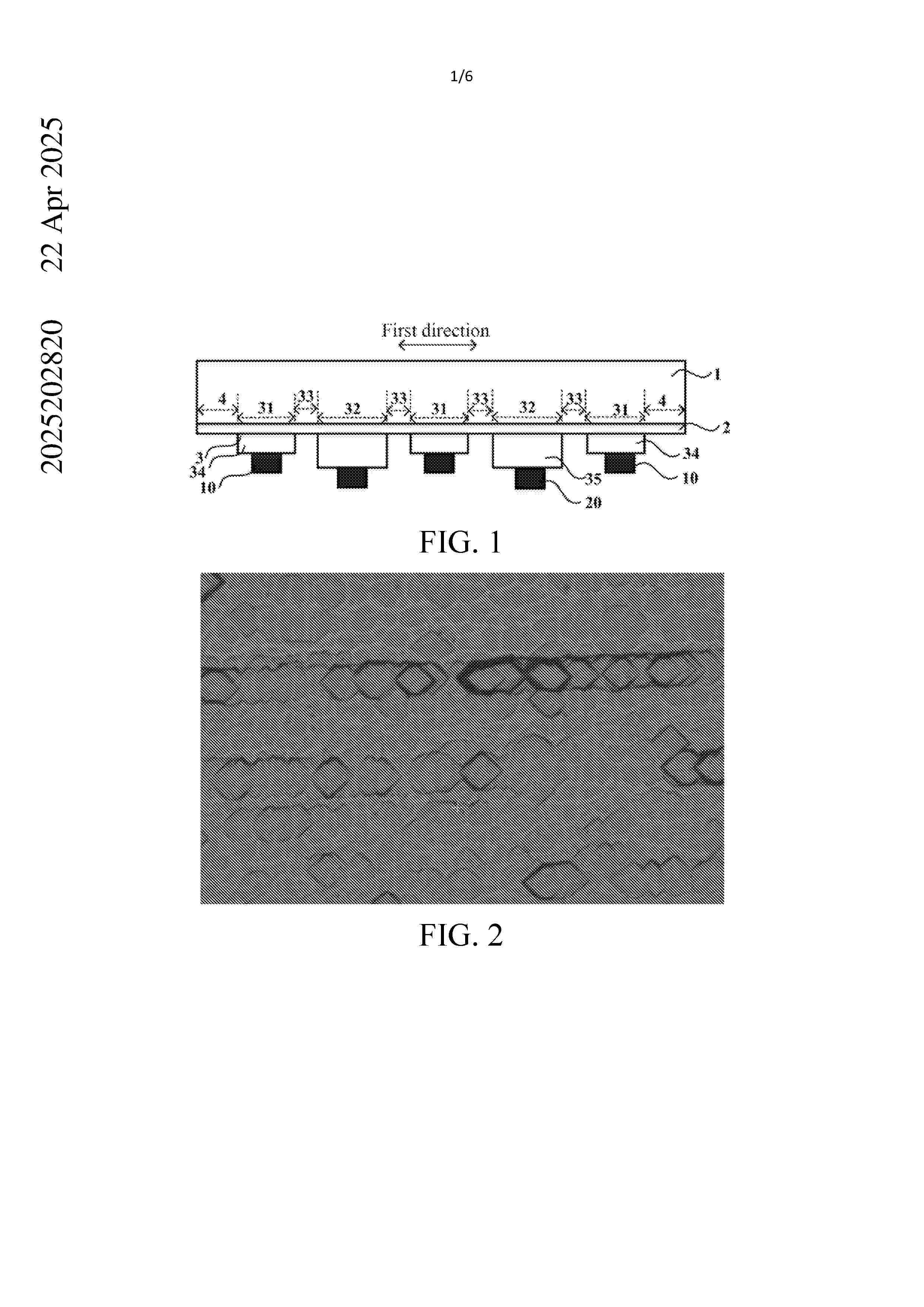
Resumen de: AU2025202820A1
The present application provides a solar cell and a photovoltaic module, and relates to the field of solar cell technologies. The solar cell includes: a semiconductor substrate; a tunnel oxide layer, located on at least one surface of the semiconductor substrate; and a doped polysilicon layer, located on a surface of the tunnel oxide layer away from the semiconductor substrate. At least part of a surface of the doped polysilicon layer away from the tunnel oxide layer is provided with silicon-containing protrusion particles. The photovoltaic module provided in the present application includes the solar cell. In the present application, the silicon- containing protrusion particles are formed on at least part of the surface of the doped polysilicon layer away from the tunnel oxide layer, so as to improve a light trapping effect of at least one surface of the solar cell, thereby improving a dual-sided ratio of the solar cell. The present application provides a solar cell and a photovoltaic module, and relates to the field of solar cell technologies. The solar cell includes: a semiconductor substrate; a tunnel oxide layer, located on at least one surface of the semiconductor substrate; and a doped polysilicon layer, located on a surface of the tunnel oxide layer away from the semiconductor substrate. At least part of a surface of the doped polysilicon layer away from the tunnel oxide layer is provided with silicon-containing protrusion particles. The photovoltaic module provided i
Resumen de: AU2024345875A1
A conveyance shuttle for conveying photovoltaic ("PV") modules along a support member. The conveyance shuttle comprises a receptacle for receiving a member of a PV module or a PV module support panel, wherein the conveyance shuttle, when coordinated with the shuttle coordinating feature, is capable of conveying the PV module or PV module support panel along a length of the support member.
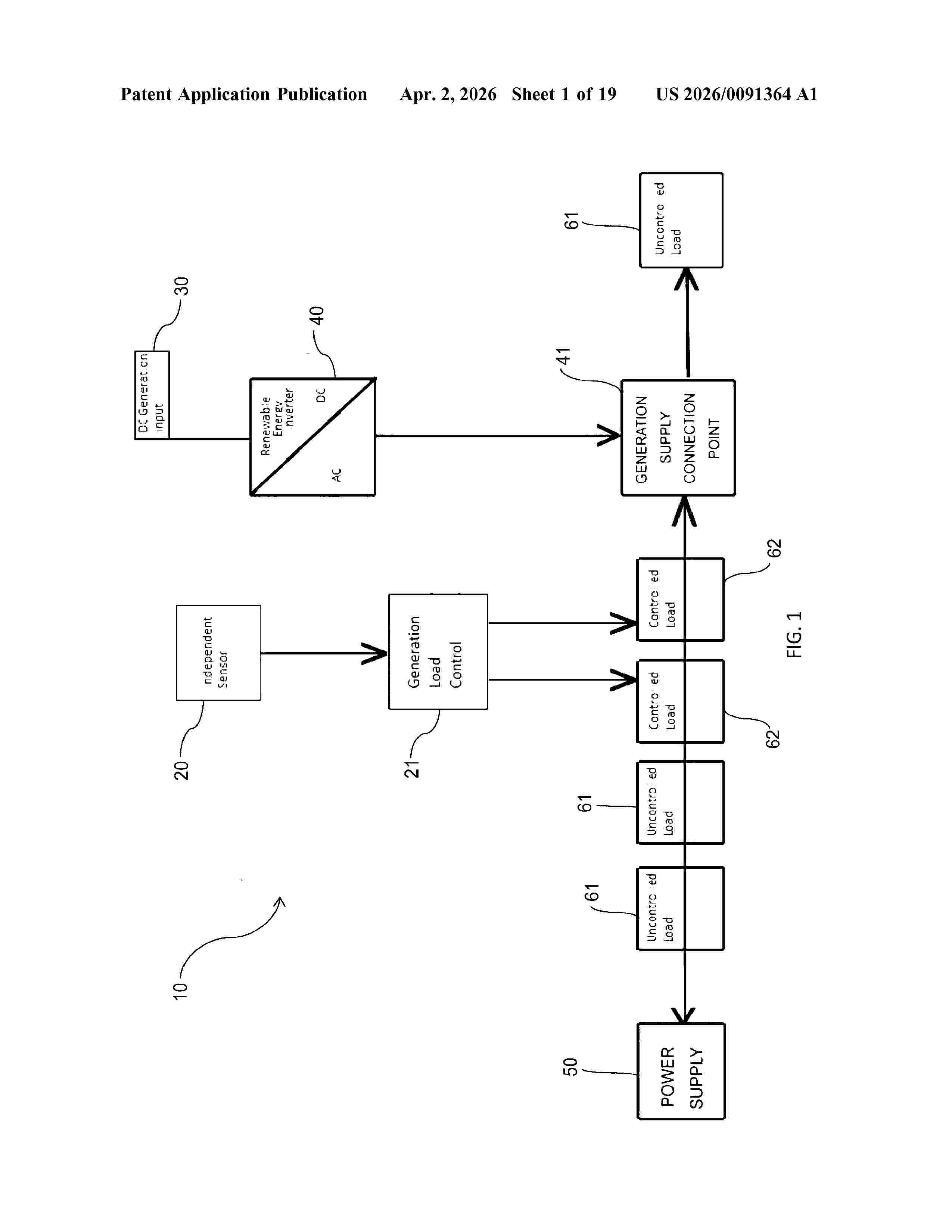
Resumen de: US20260091364A1
This invention relates to a device for controlling at least one of a plurality of electrical loads that are being supplied by at least one renewable energy generator and/or an electrical mains supply. The device comprises an energy sensor for measuring an energy parameter, wherein the energy parameter equates to a value representative of the amount of energy output by the energy sensor, the energy parameter of the energy sensor being directly proportional to the output of the at least one renewable energy generator; a controller means for determining the amount of electrical loads that can be connected or disconnected on the basis of the measured energy parameter; a switching device for connecting and disconnecting the at least one electrical load based on an output of the controller means; and wherein as the energy parameter varies the output of the controller means varies to connect and disconnect electrical loads.
Resumen de: EP4719018A2
There is provided a flexible display having a plurality of innovations configured to allow bending of a portion or portions to reduce apparent border size and/or utilize a side surface of an assembled flexible display. A flexible display apparatus, comprises a flexible base layer defined with a display area and a non-display area, a plurality of organic light-emitting diode (OLED) elements disposed on a first side of the flexible base layer in the display area, and a support layer attached to a second side of the flexible base layer, the support layer having a planar portion and a rounded edge portion arranged to extend from the display area to the non-display area, wherein the flexible base layer wraps around the rounded edge portion of the support layer in the non-display area.
Resumen de: EP4719022A2
Die vorliegende Erfindung betrifft stickstoffhaltige Heterocyclen, die sich für die Verwendung in elektronischen Vorrichtungen eignen, sowie elektronische Vorrichtungen, insbesondere organischen Elektrolumineszenzvorrichtungen, enthaltend diese Verbindungen.
Resumen de: EP4717717A1
The present invention relates to a polyolefin composition wherein the polyolefin composition of the present invention includes a modified polyolefin containing a vinyl silane group, and may thus improve the degree of crosslinking, and when the polyolefin composition of the present invention is used for manufacturing an encapsulant film, improved degree of crosslinking may be achieved while maintaining optical properties and insulating properties.
Resumen de: EP4718999A1
The present disclosure provides a solar photovoltaic module, which belongs to the technical field of manufacturing solar photovoltaic module. The solar photovoltaic module comprises a plurality of solar cell strings. Each solar cell string comprises a plurality of sub-cells whose edges are sequentially shingled and electrically connected, and the sub-cells are obtained by cutting an entire solar cell. In an extending direction of the solar cell string, for two adjacent sub-cells, a non-cut edge of a previous sub-cell is located above a cut edge of a subsequent sub-cell, and the non-cut edge of the previous sub-cell is located on a light-receiving side of the photovoltaic module. The photovoltaic module with this specific structure is able to effectively improve the power generation efficiency of the photovoltaic module, and also has advantages such as a short research and development cycle and a low research and development cost.
Resumen de: AU2024275657A1
A method and system of analyzing health of a solar tracker, including confirming solar tracker is in a starting position, driving solar tracker through a range of angles, collecting data regarding performance of solar tracker, analyzing the collected data, and presenting one or more aspects of the collected data on a user interface indicating the health of the solar tracker.
Resumen de: EP4718712A1
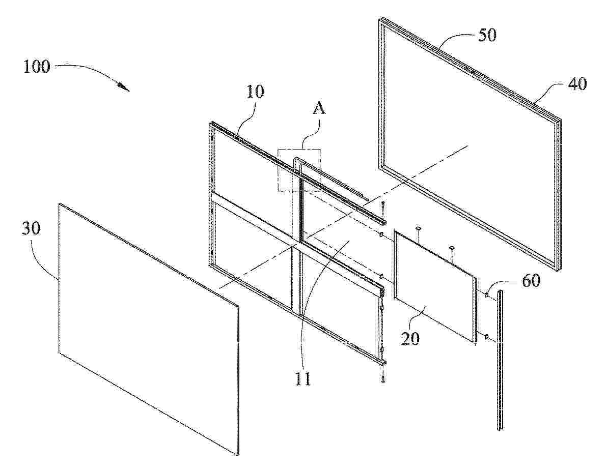
A perovskite solar energy generation module (100,100A,100B,100C) includes a solar panel frame (10), at least one solar panel (20,20A,20B,20C), a first protective panel (30), a second protective panel (40), and a sealing structure (50). The solar panel (20,20A,20B,20C) is disposed on the solar panel frame (10). The solar panel frame (10) is engaged between the first protective panel (30) and the second protective panel (40) and is surrounded by the sealing structure (50). A sealed cavity (51) formed between the first protective panel (30), the second protective panel (40), and the sealing structure (50), preventing the solar panel (20,20A,20B,20C) from being easily oxidized due to environment and hence improving the stability. A construction-shading device (200,200A,200B,200C) is further provided, wherein the perovskite solar energy generation module (100,100A,100B,100C) is disposed in an outer frame (70,70A,70B,70C). The construction-shading device (200,200A,200B,200C) could have different designs to meet different architectural styles and requirements.
Resumen de: WO2025022218A1
Photovoltaic plant comprising: -a first row (11) of photovoltaic panels comprising a first panel (110); -a second row (12) of photovoltaic panels comprising a second panel (120); -a first support (3) for supporting both the first panel (110) and the second panel (120); said first support (3) extending between the first and the second row (11, 12) and being a ballast at least partly made of concrete or cementitious material connected to the first and to the second panel (110, 120). A rectilinear channel (9) being present between the first and the second row (11, 12). The first support (3) comprises a first portion (31) for supporting the first panel (110) and a second portion (32) for supporting the second panel (120); the first and the second portion (31, 32) are part of the same body; the first support (3) extends mainly along a first direction (30) that connects the first and the second row (11, 12). The first panel (110) extends towards the second row (12), going beyond the first portion (31) and/or the second panel (120) extends towards the first row (11), going beyond the second portion (32).
Resumen de: CN121219194A
The invention relates to a maintenance and repair vessel (7) for a floating solar cell power plant for the installation, maintenance and cleaning of solar panels (6) and solar cell modules (1). The boat (7) comprises at least two parallel elongated pontoons (8) and at least two cross beams (9) connecting the pontoons (8), the pontoons (8) are of hollow structure and provide buoyancy for the boat (7), at least one end (11) of each pontoon (8) is arranged at an inclined angle, so that the boat can cross the mooring line (2) connecting the solar cell modules (1) without damaging the mooring line (2).
Resumen de: EP4717997A1
Solar tracker (1) for stand-alone power supply, comprising a support frame; a main solar module (3) to convert incident light into heat or electric power, having a main receiving surface rotatably mounted to the support frame around a rotation axis; an actuator (4) to move the main solar module with respect to the support frame around the rotation axis between a sunrise and a sunset position; a control arrangement to control the actuator, comprising a tracking solar module (5) electrically connected to the actuator to convert incident light into electric power for powering the actuator, wherein the tracking solar module is coupled to the main solar module to rotate therewith, wherein the tracking solar module is positioned with respect to the main receiving surface to receive incident light and activated the actuator to rotate the main receiving surface towards the sun, wherein the control arrangement comprises a return solar module (6) electrically connected to the actuator to convert incident light into electric power for powering the actuator, wherein the return solar module is positioned such that, when the main receiving surface is arranged in the sunset position, the return solar module is uncovered for receiving incident light and the actuator can be activated by the return solar module to rotate the main receiving surface into the sunrise position; when the main receiving surface is in the sunrise position, the return solar module is covered to block incident light, s
Resumen de: EP4718428A1
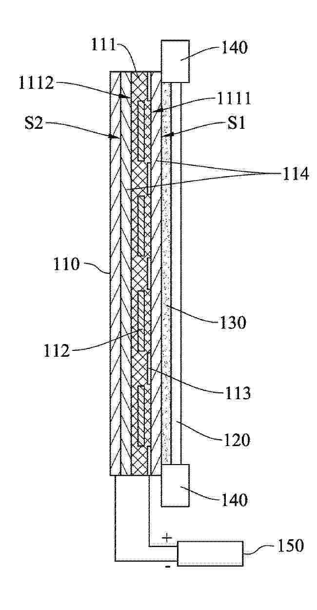
A self-powered display device (100) includes a solar module (110) and a display panel (120). The solar module (110) has a first surface (S1) and a second surface (S2) opposite to each other, and includes a polymer layer (111), a plurality of solar cells (112) and a plurality of opaque patterns (113). The solar cells (112) are electrically connected to each other and embedded in the polymer layer (111) at intervals. The opaque patterns (113) are embedded in the polymer layer (111), wherein projections of the opaque patterns (113) on the first surface (S1) are respectively located between projections of the solar cells (112) on the first surface. The display panel (120) is disposed on the first surface (S1) of the solar module. The solar module (110) is configured to receive the light from the first surface and the second surface.
Resumen de: EP4717365A1
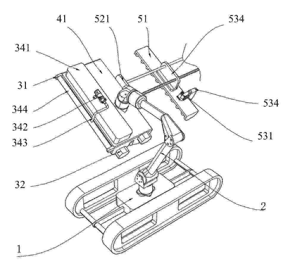
The present disclosure relates to a device for cleaning a photovoltaic panel. The device is capable of automatically cleaning the photovoltaic panel by using a cleaning liquid, and includes an unmanned vehicle mechanism, a multi-joint robot arm, and a cleaning mechanism, where one end of the multi-joint robot arm is arranged on the unmanned vehicle mechanism, and the other end of the multi-joint robot arm is connected to the cleaning mechanism; and the cleaning mechanism includes a cleaning support frame for providing support, a first electric motor for providing power, a soft brush roller for cleaning the photovoltaic panel, and a spraying assembly for spraying the cleaning liquid, the first electric motor, the soft brush roller, and the spraying assembly are all arranged on the cleaning support frame, an output end of the first electric motor is connected to the soft brush roller and is configured to drive the soft brush roller to rotate, and the spraying assembly is capable of spraying the cleaning liquid onto the soft brush roller.
Resumen de: EP4718707A1
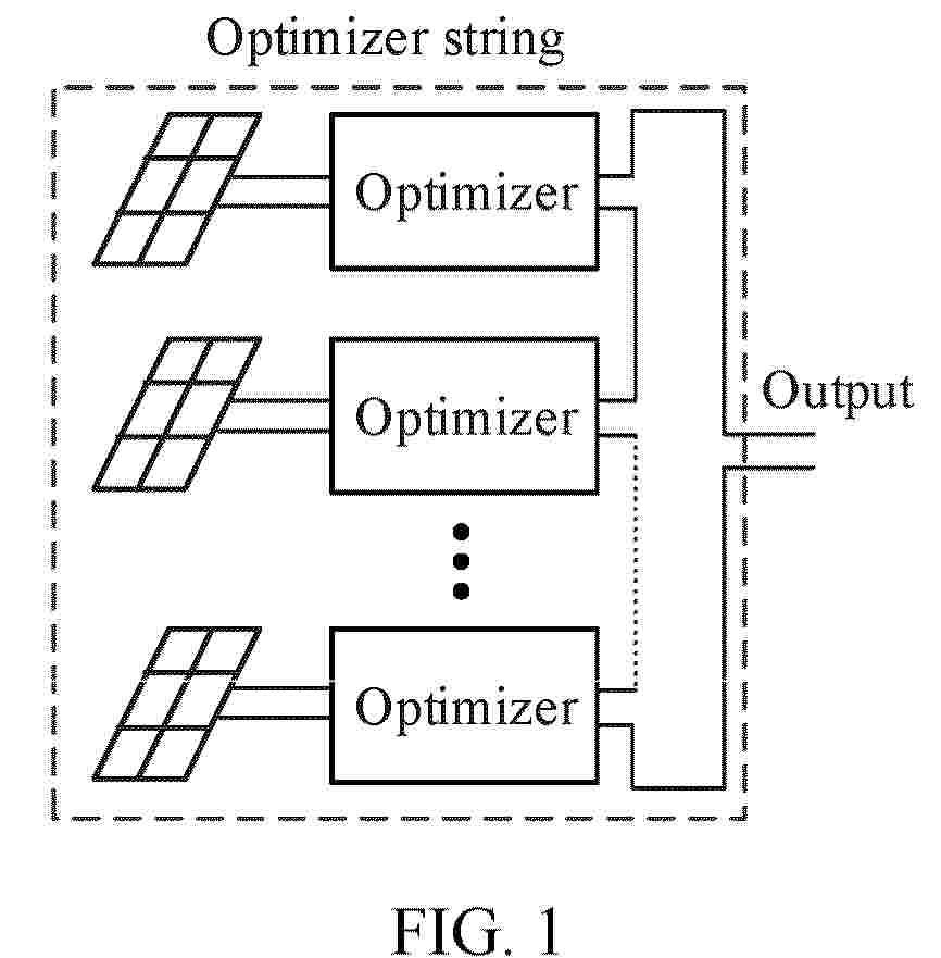
This application provides an inverter and an inverter control method. The inverter includes a plurality of direct current boost circuits, a direct current bus, and an inverter circuit. The plurality of direct current boost circuits each are configured to receive a direct current input from an optimizer, and output the direct current input from the optimizer to the inverter circuit through the direct current bus. The inverter circuit is configured to receive direct current inputs from the plurality of direct current boost circuits, and output the direct current inputs from the plurality of direct current boost circuits to a load or a grid. When the plurality of direct current boost circuits work in an MPPT state, if input voltages of n direct current boost circuits in the plurality of direct current boost circuits are all greater than or equal to a first threshold, a controller controls switching transistors in m direct current boost circuits in the n direct current boost circuits to keep turned off. m and n are integers greater than 0. n ≥ m. The first threshold is greater than or equal to a minimum voltage limit of the direct current bus.
Resumen de: EP4718661A1
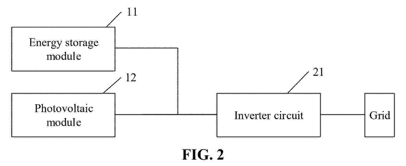
A photovoltaic system, relating to the field of power conversion devices. The photovoltaic system comprises: a photovoltaic module (12), which is used for supplying power to an energy storage module (11) and/or an inverter circuit (21); the energy storage module (11), which is used for receiving the power that is output by the photovoltaic module (12), or supplying power to the inverter circuit (21) when the photovoltaic module (12) does not operate; and the inverter circuit (21), which is used for inverting to a power grid the power supplied by the photovoltaic module (12) and/or the energy storage module (11). The photovoltaic module (12) and the energy storage module (11) can be directly connected to the inverter circuit (21), thereby preventing the loss caused by the conversion of a direct current-direct current module during the power exchange between the photovoltaic module (12) and the energy storage module (11). In addition, the power exchange between the photovoltaic module (12) and the energy storage module (11) is completed on a low-voltage side, thereby ensuring better safety.
Resumen de: AU2024292012A1
A frame for a photovoltaic module may include: a base portion having an outer lip and a bottom surface while also defining an opening configured to receive a first mounting element therein; at least one leg extending from the base portion; and a panel support portion extending from the at least one leg and configured to secure a solar panel therein. The outer lip and the at least one leg may define a cavity.
Resumen de: EP4718997A1
The present invention relates to: a frame-integrated photovoltaic module having a G-to-S structure, wherein the module replaces a conventional photovoltaic module having a G-to-G structure or a G-to-B structure and does not require a process of coupling a photovoltaic module and a frame; a BIPV system using same; and a method for manufacturing a frame-integrated photovoltaic module having a G-to-S structure, whereby a photovoltaic module having a G-to-S structure in which the photovoltaic module and the frame are integrated can be manufactured through a single laminating process. The frame-integrated photovoltaic module having a G-to-S structure comprises: a planar frame providing a mounting space for an encapsulant, a photovoltaic cell, and a front light-transmitting glass, and serving as a mechanical medium which enables the module to be mounted to a specific structure; an encapsulant in which the photovoltaic cell provided on the planar frame is encapsulated; and front light-transmitting glass provided on the encapsulant in which the photovoltaic cell is encapsulated.
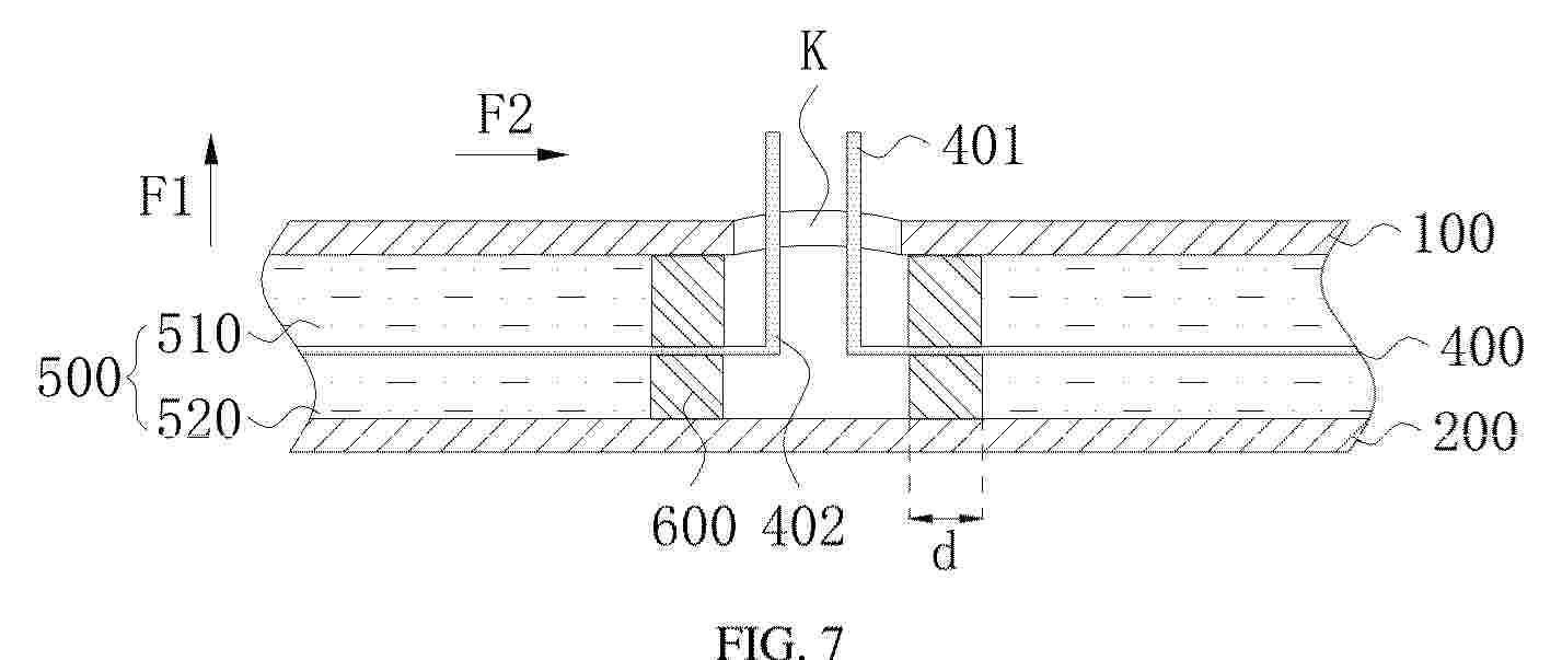
Resumen de: EP4719000A1
A photovoltaic assembly, comprising: a back panel (100) and a front panel (200), which are arranged opposite each other; battery strings (300), which are arranged between the back panel (100) and the front panel (200); bus-bars (400), which are electrically connected to the battery strings (300); and waterproof structures (600), which are sandwiched between the back panel (100) and the front panel (200), wherein a lead hole (K) is provided in the back panel (100), each bus-bar (400) is provided with a lead-out end (401), and the lead-out end (401) is threaded through the lead hole (K) by means of a waterproof structure (600); and the orthographic projection of the lead hole (K) on a reference plane is located within an outer contour of the orthographic projections of the waterproof structures (600) on the reference plane, the reference plane being a plane parallel to the plane where the lead hole (K) is located.
Resumen de: EP4719011A1
The present application discloses a composite electrode, a solar cell, methods for preparing the same, a power consuming apparatus, and an energy storage apparatus. The composite electrode includes a conductive oxide substrate and a metal doped in the conductive oxide substrate. The composite electrode has good stability performance, and also functions as a matrix to protect the doped metal, thereby improving chemical stability of the metal. The doped metal modifies the conductive oxide substrate, thereby significantly improving electrical conductivity of the composite electrode. A back electrode of the solar cell includes the composite electrode. The photoelectric performance of the solar cell is enhanced and remains stable.
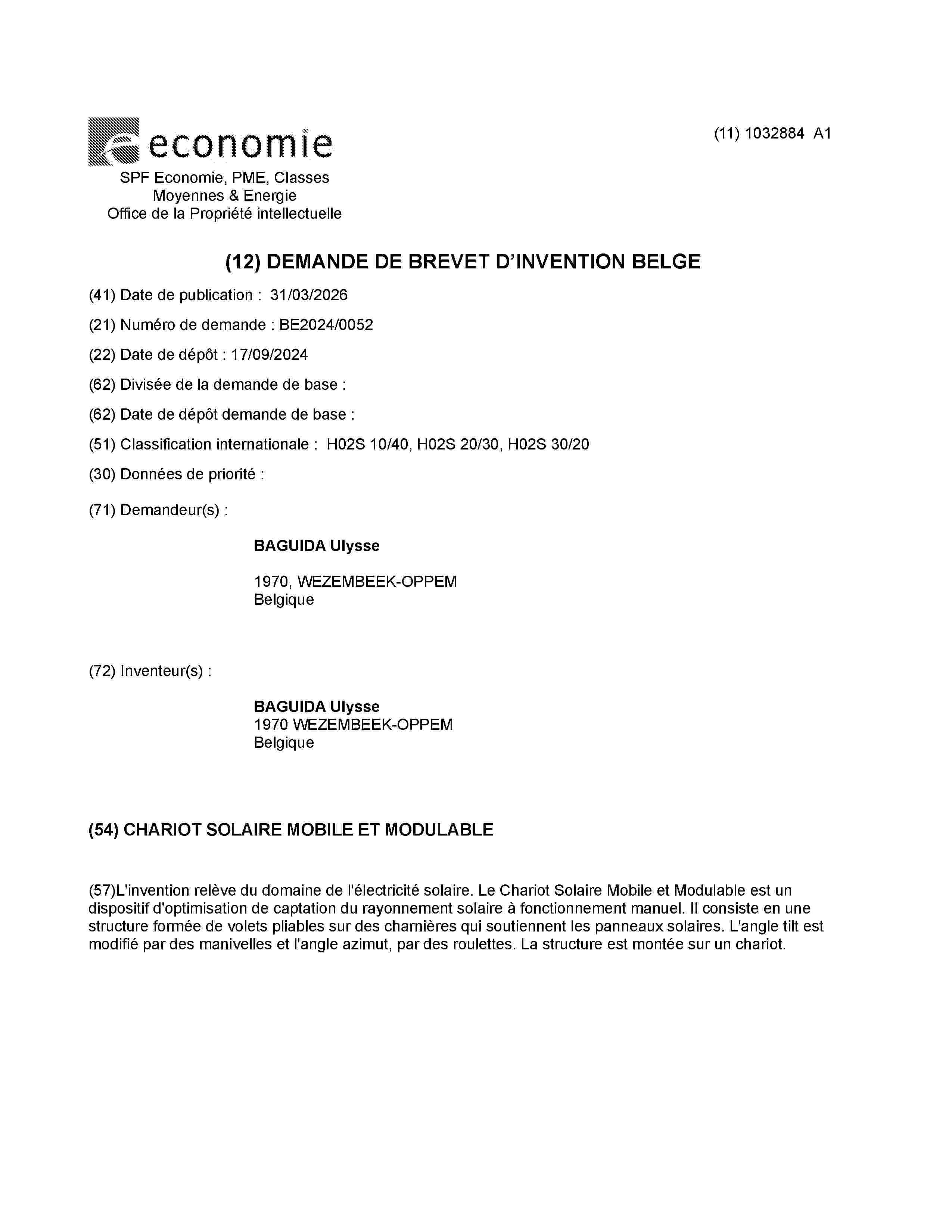
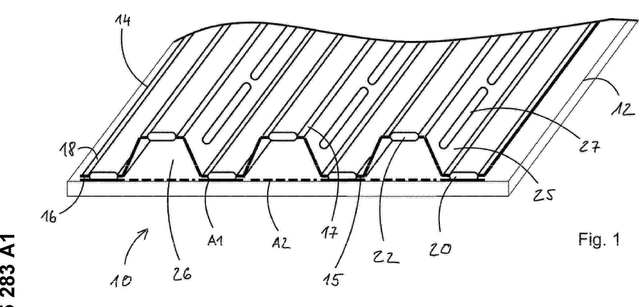
Resumen de: BE1032884A1
L'invention relève du domaine de l'électricité solaire. Le Chariot Solaire Mobile et Modulable est un dispositif d'optimisation de captation du rayonnement solaire à fonctionnement manuel. Il consiste en une structure formée de volets pliables sur des charnières qui soutiennent les panneaux solaires. L'angle tilt est modifié par des manivelles et l'angle azimut, par des roulettes. La structure est montée sur un chariot.
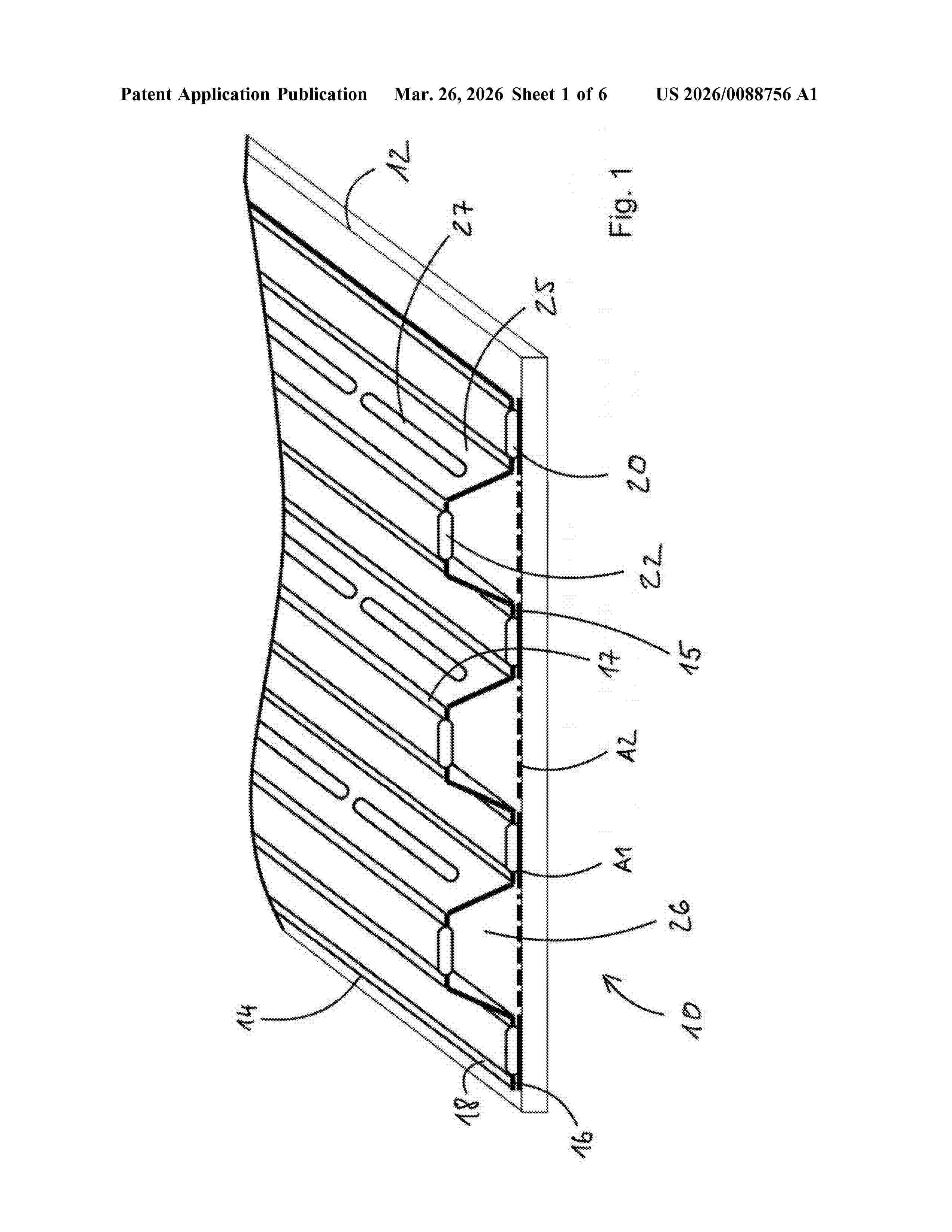
Resumen de: US20260088756A1
A PVT module having a photovoltaic cell and a thermal absorber includes a thermal absorber having a composite plate structure comprising overlapping plates that are connected to one another by material bond in coupling surfaces. The plates are separated from one another outside the coupling surfaces, wherein channels are formed between the plates outside the coupling surfaces by a forming process on at least one of the plates, wherein the channels form a channel system integrated in the composite plate structure. A method for manufacturing a PVT module and PVT arrangement with at least two PVT modules are further disclosed.
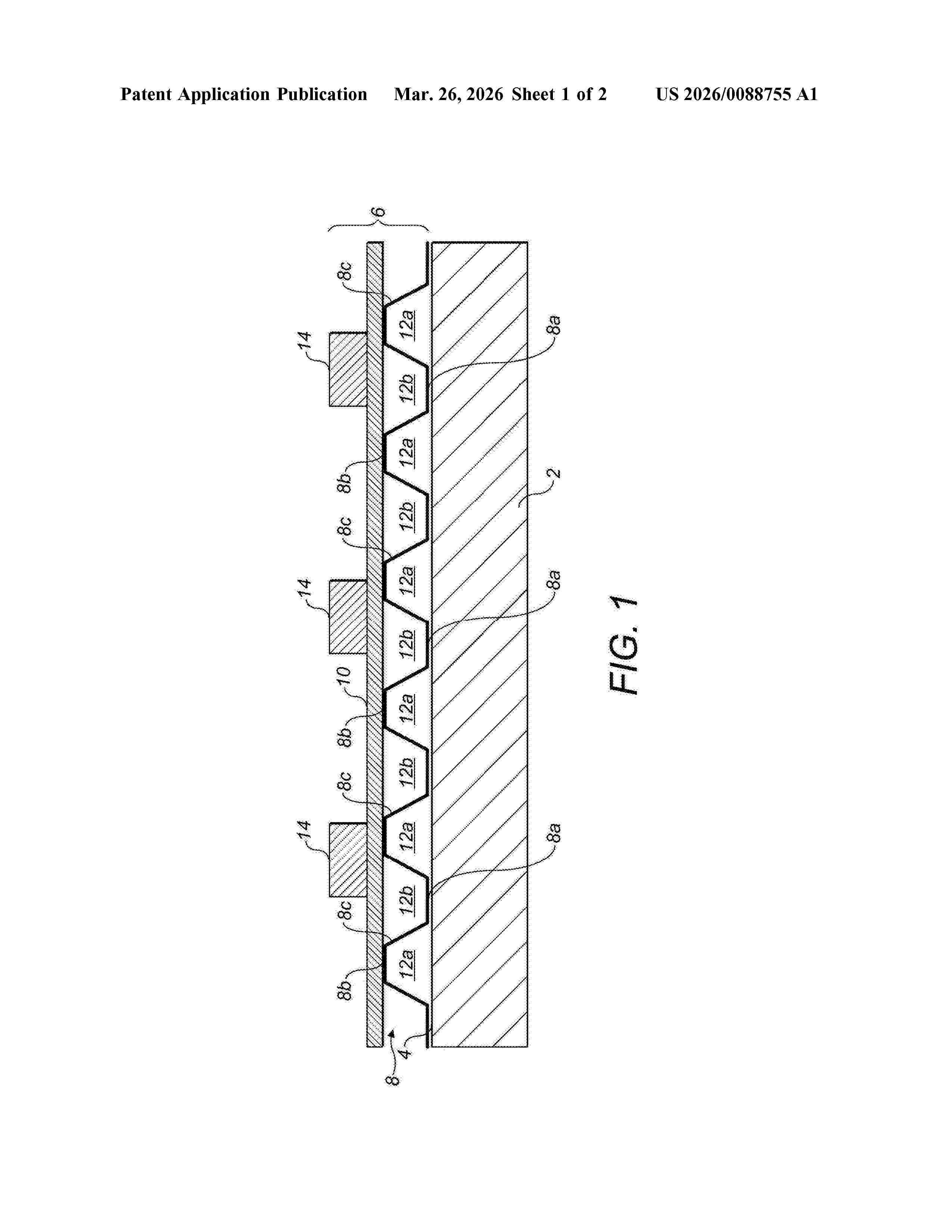
Resumen de: US20260088755A1
A cooling apparatus for a photovoltaic panel, the apparatus comprising a thermally transmissive PV contact element; a backing sheet coupled to one side of the PV contact element; and one or more electric fans, wherein the thermally transmissive PV contact element includes planar PV contact portions and defines a plurality of air channels therein; wherein the backing sheet carries the or each electric fan; and wherein the or each electric fan generates an airflow along the channels defined by the PV contact element.
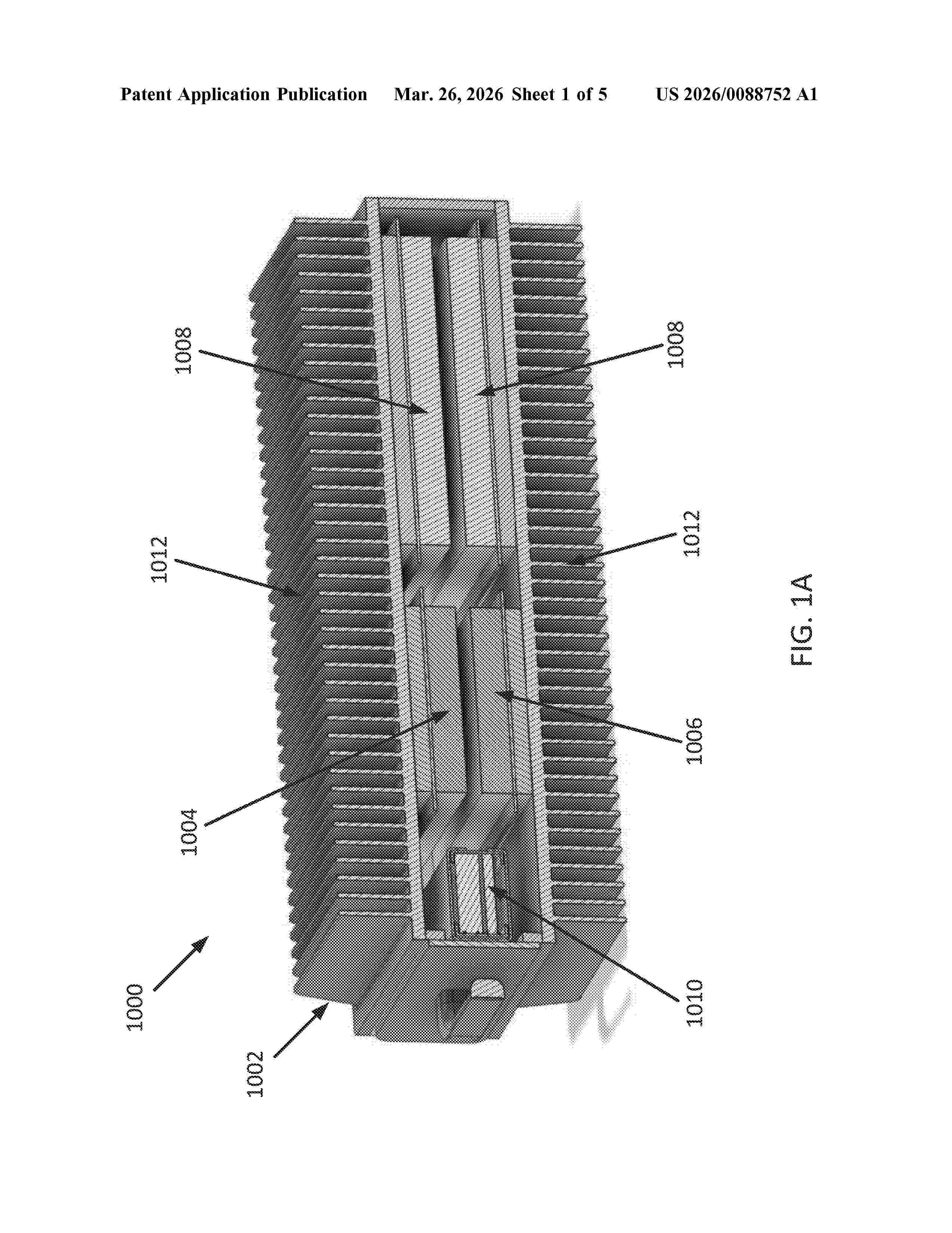
Resumen de: US20260088752A1
An integrated system for solar tracking and DC/DC conversion can include a housing with heat sink fins, a DC power supply configured to receive DC power from one or more solar panels and supply DC power to internal components, and a self-powered controller electrically connected to the DC power supply. The self-powered controller outputs control signals to one or more motors to orient the solar panels. The system further includes a plurality of configurable power blocks that are selectively operable as DC/DC converters to perform maximum power point tracking or as DC/AC converters. A battery module is detachably couplable to the housing by a connector and is electrically connected to the DC power supply to provide backup power. The housing can be formed of a heat-conducting material to enable passive cooling. The battery module can include a seal to prevent ingress of debris and fluids.
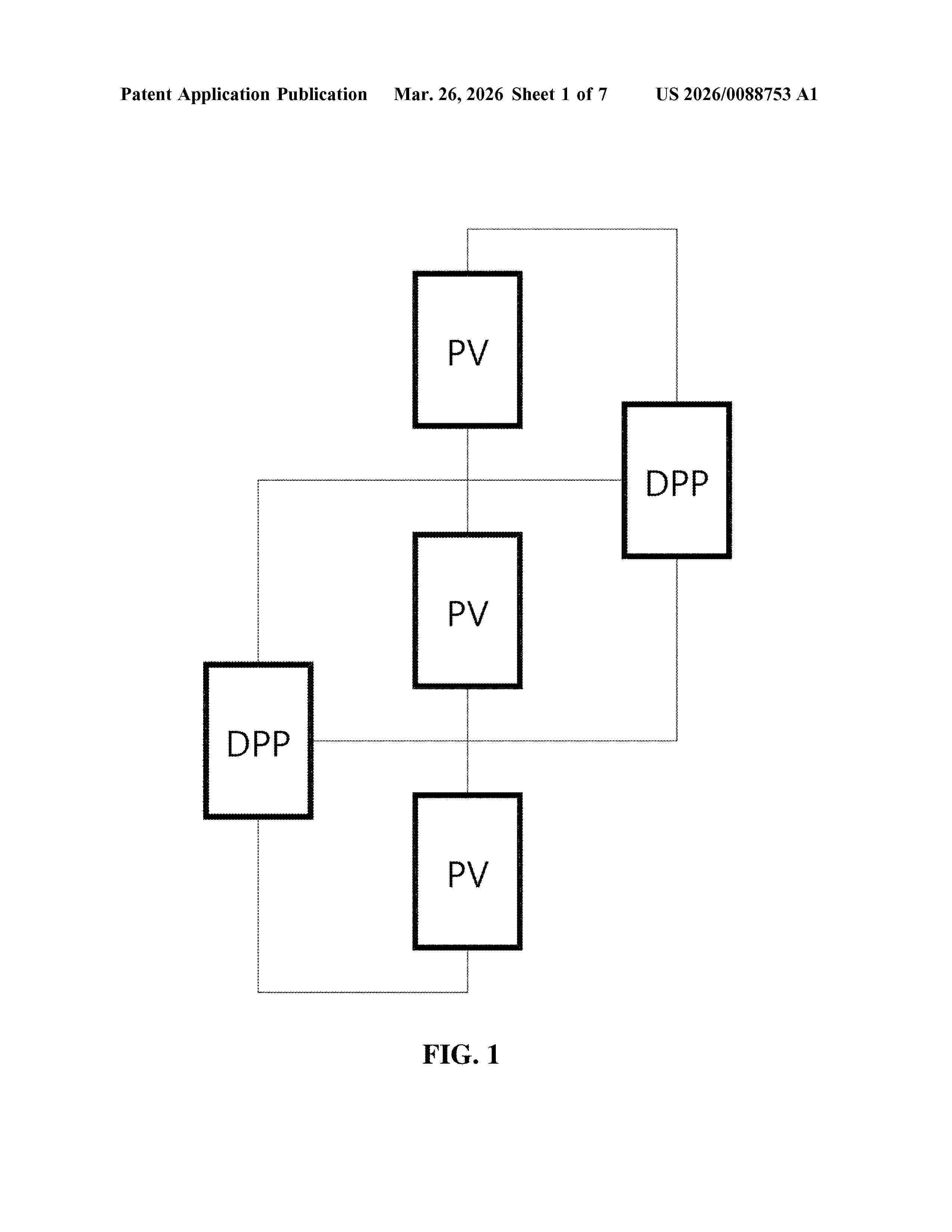
Resumen de: US20260088753A1
A differential power processing apparatus for photovoltaic power generation may include: a first terminal connected to a negative output terminal of a first photovoltaic module located outside; a second terminal connected to a positive output terminal of the first photovoltaic module; a third terminal connected to a negative output terminal of a second photovoltaic module located outside; a fourth terminal connected to a positive output terminal of the second photovoltaic module; a first switch located between the first terminal and the fourth terminal and mediating an electrical connection between the first photovoltaic module and the second photovoltaic module; a second switch connected between the second terminal and the third terminal; and a third switch including a first end connected to the third terminal, and a second end connected to the second switch.
Resumen de: US20260088754A1
A system and method for phase-change cooling and thermal management includes electrically coupling an evaporation apparatus to an external circuit, wherein the evaporation apparatus includes a top planar layer including a top electrode, a bottom planar layer including a bottom electrode, and an evaporation layer between the top planar layer and the bottom planar layer, thermally coupling the evaporation apparatus to a heat source, and monitoring, using the external circuit, an operation status of the evaporation apparatus. The evaporation layer includes a carbon structure. The carbon structure is electrically coupled to the top electrode and the bottom electrode. Water is vaporized at a surface of the carbon structure.
Resumen de: WO2026061622A1
The invention relates to a device (10) for at least one solar module (20), the device (10) having a fastening section (11) for fastening the device (10) in a region of the at least one solar module (20), and the device (10) having at least one cover element (12) for covering a surface (21) of the at least one solar module (20), the cover element (12) being designed to be expandable in order to increase a surface (21) of the at least one solar module (20) that can be covered by means of the cover element (12), and the cover element (12) being designed to be retractable in order to reduce the surface (21) of the at least one solar module (20) that can be covered by means of the cover element (12).
Resumen de: US20260088751A1
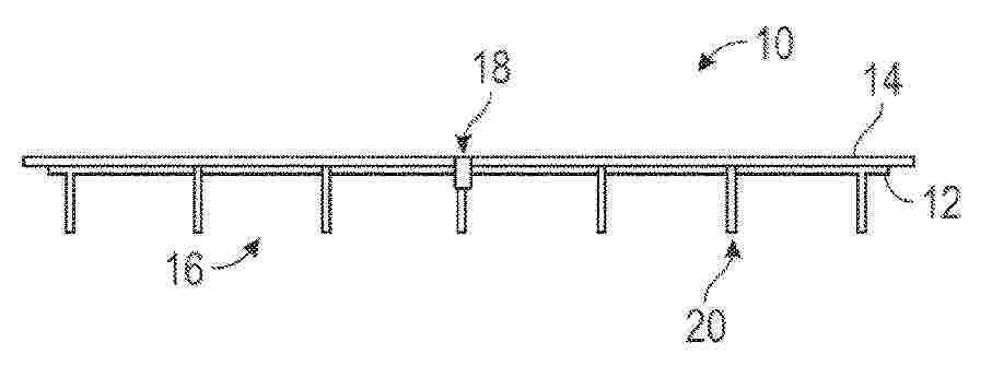
A truss foundation system is disclosed for supporting a single-axis solar tracker in agrivoltaic installations. The system includes a screw anchor foundation component having an embedment end and an opposing driving end. A Y-shaped screw cap sleeves over the driving end of the screw anchor and includes a lower portion and a pair of upper portions extending at reciprocal angles relative to a vertical midline. A pair of truss legs are connected to the respective upper portions of the screw cap and extend upwardly to support the tracker structure.
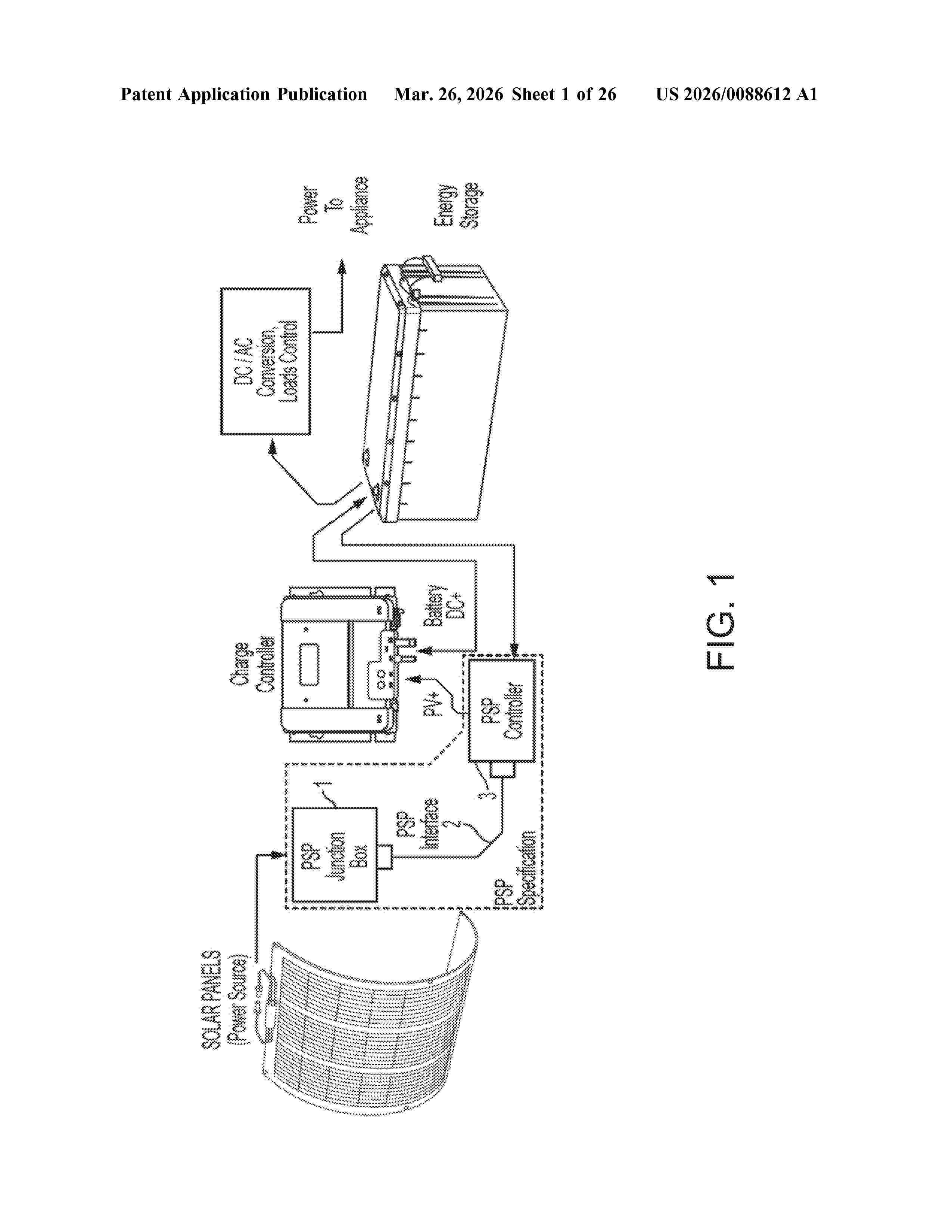
Resumen de: US20260088612A1
A power control system includes a pluggable power source (PPS) junction box operable to receive and aggregate power from one or more energy sources. The system includes a PPS controller operable to control an enable signal and provide the power to an energy storage device or direct load device. The system includes a PPS interface operable to communicate the power from the PPS junction box to the PPS controller and communicate the enable signal from the PPS controller to the PPS junction box. The PPS controller controls the enable signal responsive to at least (i) an amount of power available from the one or more energy sources and (ii) an amount of energy stored at the energy storage device or required to supply the direct load device. The PPS interface communicates the power from the PPS junction box to the PPS controller based on the enable signal.
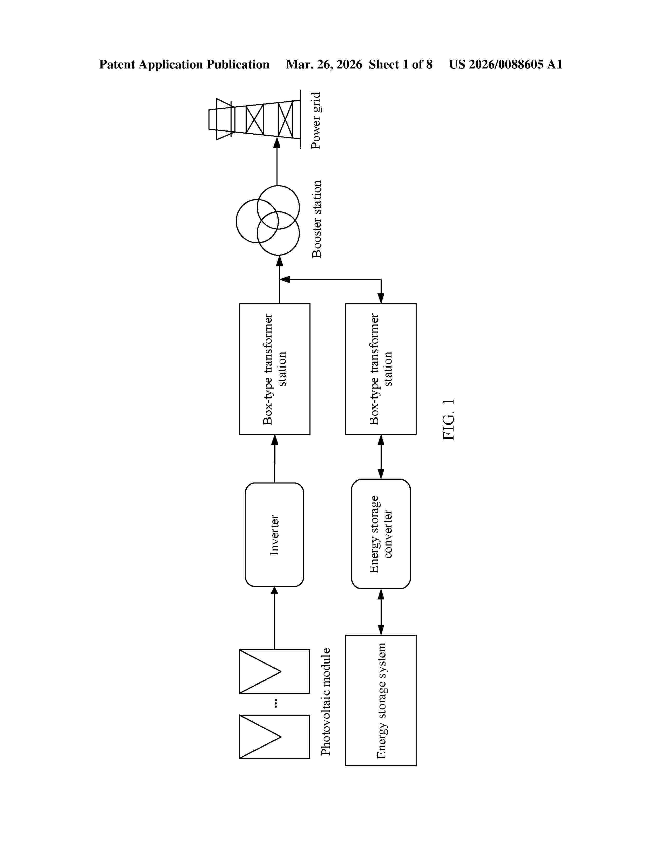
Resumen de: US20260088605A1
A photovoltaic inverter includes a first switch group, a second switch group, an anti-reverse circuit, a DC/DC power conversion circuit, a bus capacitor, and a controller. A first photovoltaic string is connected to the bus capacitor via the first switch group and the anti-reverse circuit sequentially. A plurality of photovoltaic strings is connected to the DC/DC power conversion circuit via a second switch, and the plurality of photovoltaic strings include the first photovoltaic string. The controller is configured to: turn on all switches in the second switch group; and when an overcurrent occurs in a current flowing through a part of switches in the second switch group, turn off the part of switches that is in the second switch group and in which the overcurrent occurs.
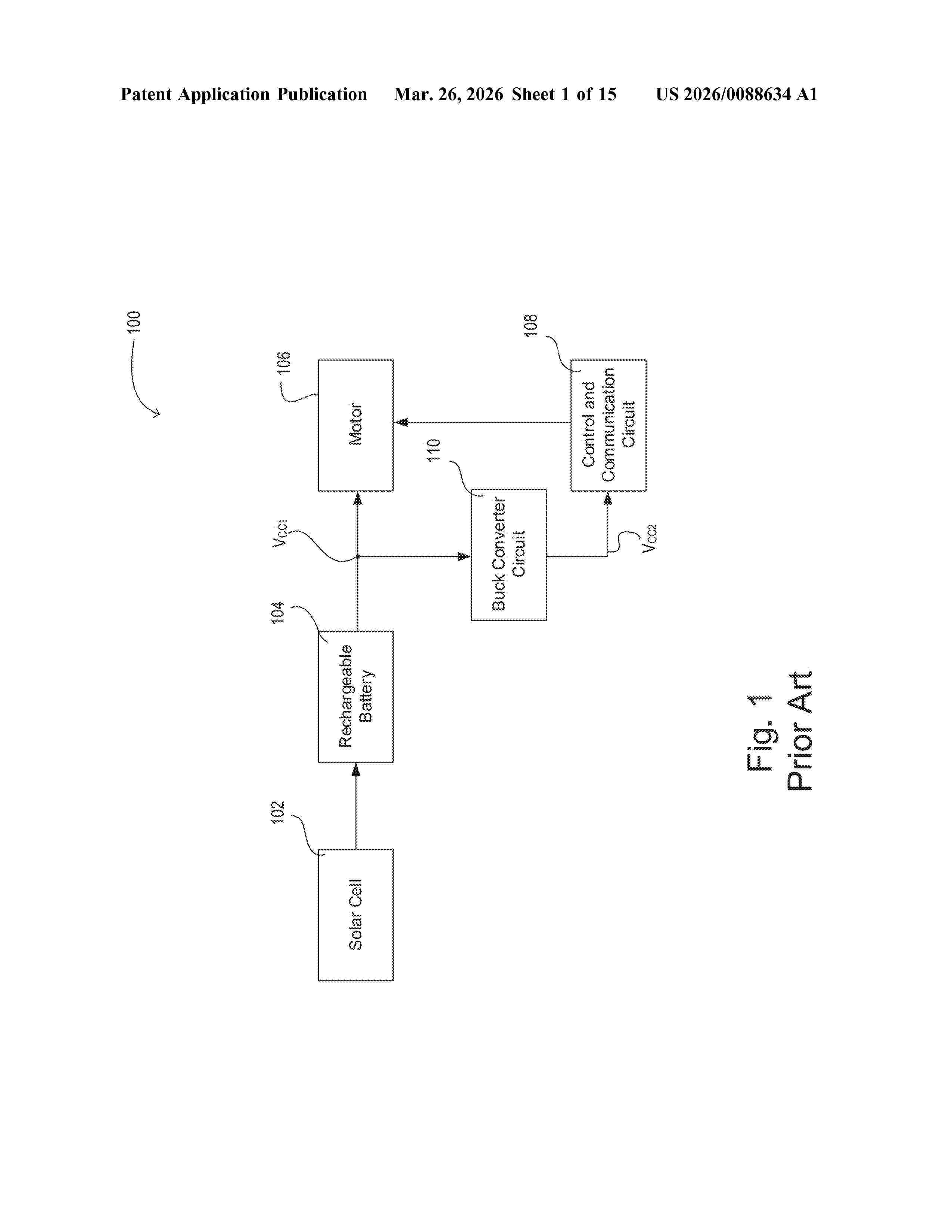
Resumen de: US20260088634A1
A battery-powered device, such as a motorized window treatment, may provide power to an electrical load, such as a motor. The device may also include a control circuit and a communication circuit. In addition to the battery, the device may be configured to receive power from a supplemental power source, such as a solar cell or wireless RF power supply, through which to power the control and communication circuits. The device may include a voltage monitor and a switch to intelligently control whether the battery or the supplemental power source is powering the control and communication circuits.
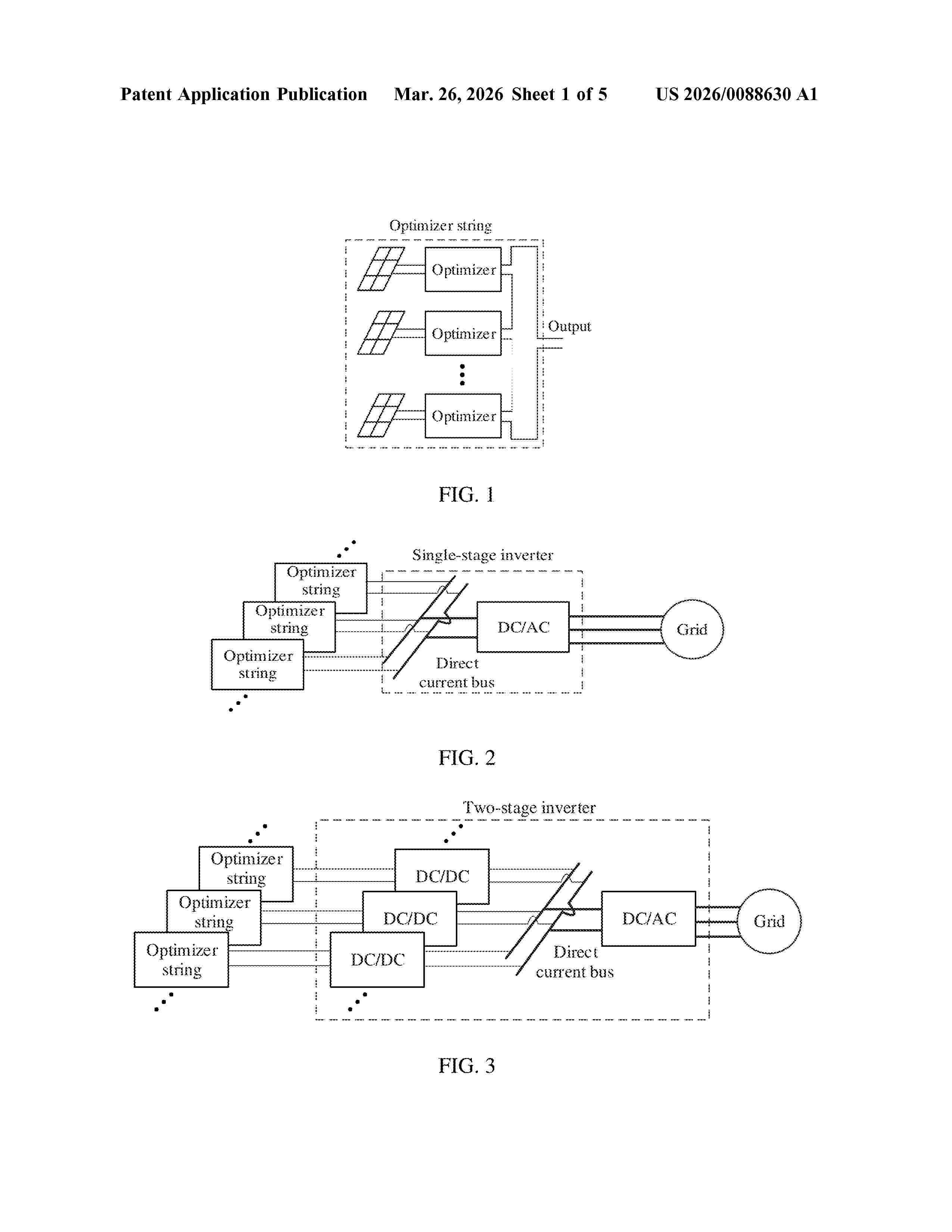
Resumen de: US20260088630A1
An inverter, an inverter control method, and a system. When the plurality of direct current boost circuits operate in a maximum power point tracking (MPPT) state, if input voltages of n direct current boost circuits in the plurality of direct current boost circuits are each greater than or equal to a first threshold, a controller controls switching transistors in m direct current boost circuits in the n direct current boost circuits to remain turned off. m and n are integers greater than 0 with n≥m. The first threshold is greater than or equal to a minimum voltage limit of the direct current bus.
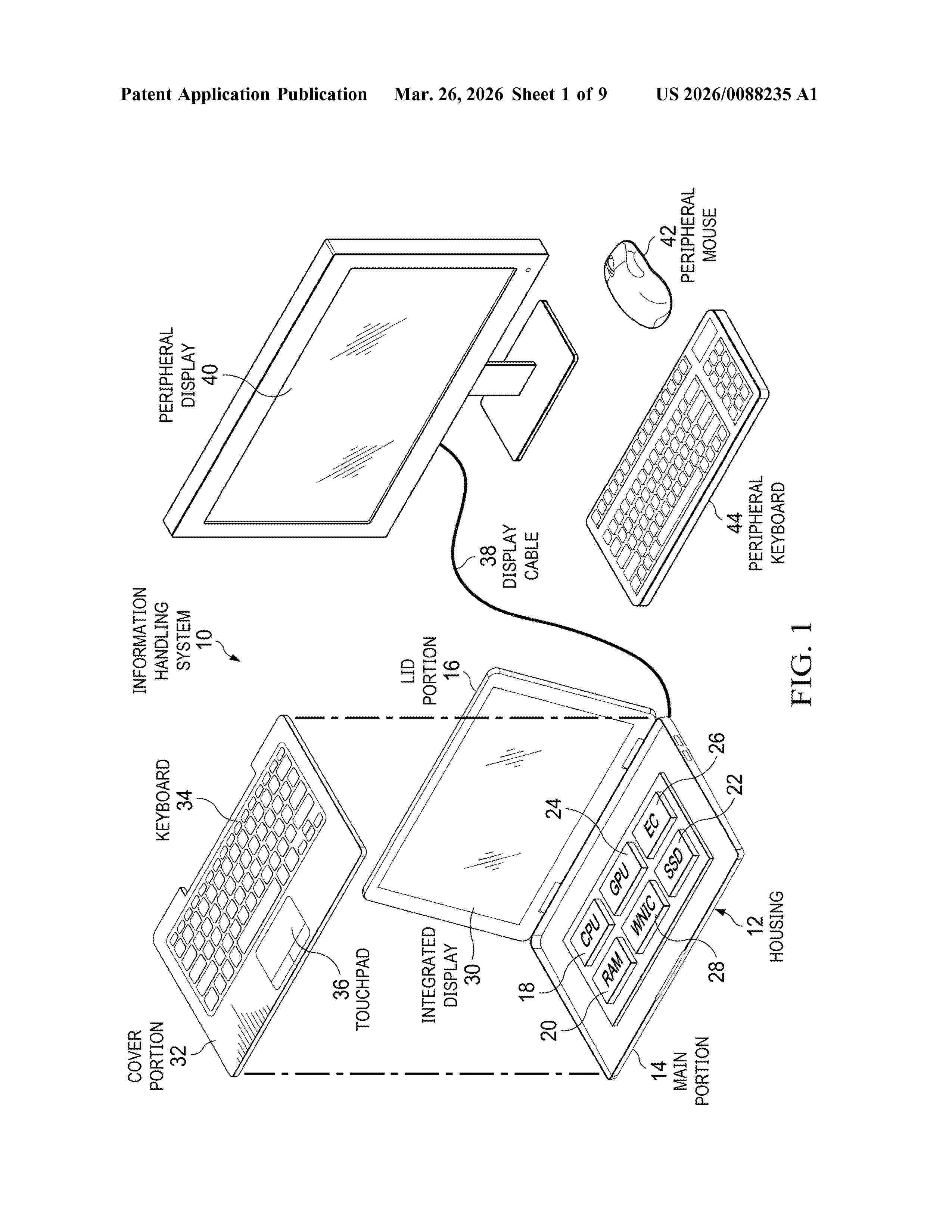
Resumen de: US20260088235A1
An information handling system keyboard liquid crystal display (LCD) presents visual images illuminated by light emitting diodes (LEDs) at an underside of the LCD within the keyboard, such as to present function keys or a number pad. A photovoltaic panel placed over the LCD recycles illumination passing through the LCD and also absorbs ambient light to convert the light to a current that is applied to charge a battery of the keyboard.
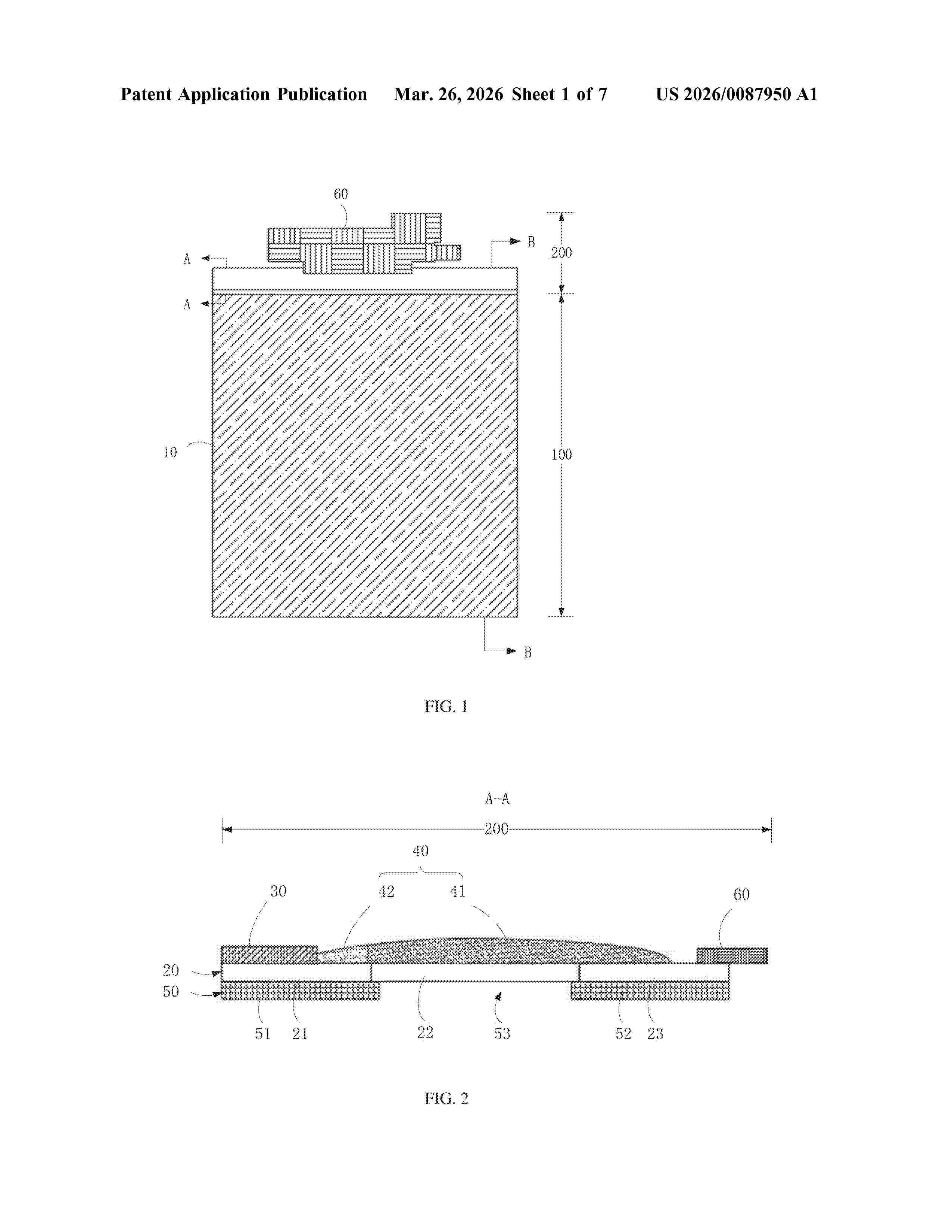
Resumen de: US20260087950A1
A display module, a manufacturing method thereof, and a display device are provided herein. The display module includes a display panel, a functional layer, and a sealant layer disposed on the display panel, the sealant layer includes a first sealant section spaced apart from the functional layer and a second sealant section filled between the first sealant section and the functional layer, two ends of the second sealant section are bonded to the functional layer and the first sealant section respectively and an elastic modulus of the second sealant section is smaller than an elastic modulus of the first sealant section.
Resumen de: AU2026201695A1
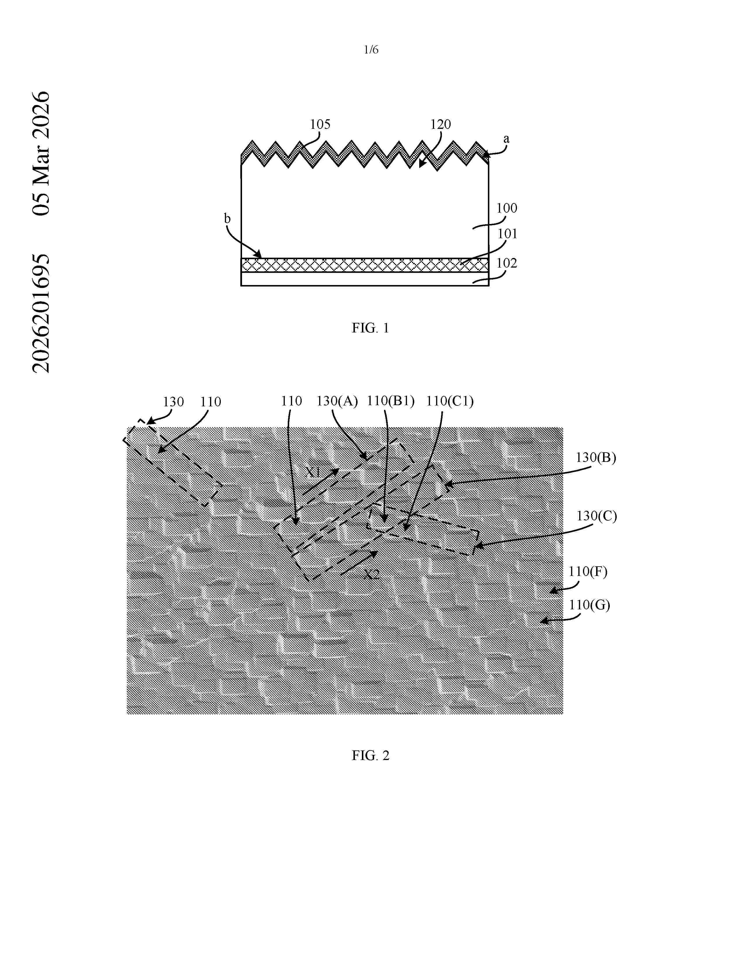
Embodiments of the present disclosure relate to the field of solar cell technologies, and provide a solar cell, a method for preparing the same, and a photovoltaic module. The solar cell includes an N-type silicon substrate including a front surface and a rear surface opposite to the front surface. The front surface includes a plurality of pyramid structures, the rear surface includes a plurality of grooves, and some of the plurality of grooves are sequentially arranged along one arrangement direction. The solar cell includes a passivation layer formed over the front surface, a tunneling dielectric layer formed over the rear surface, and a doped conductive layer formed over the tunneling dielectric layer. Embodiments of the present disclosure at least help improve the photoelectric conversion efficiency of the solar cell by changing a morphology of the rear surface of the N-type silicon substrate. ar a r
Resumen de: AU2026201761A1
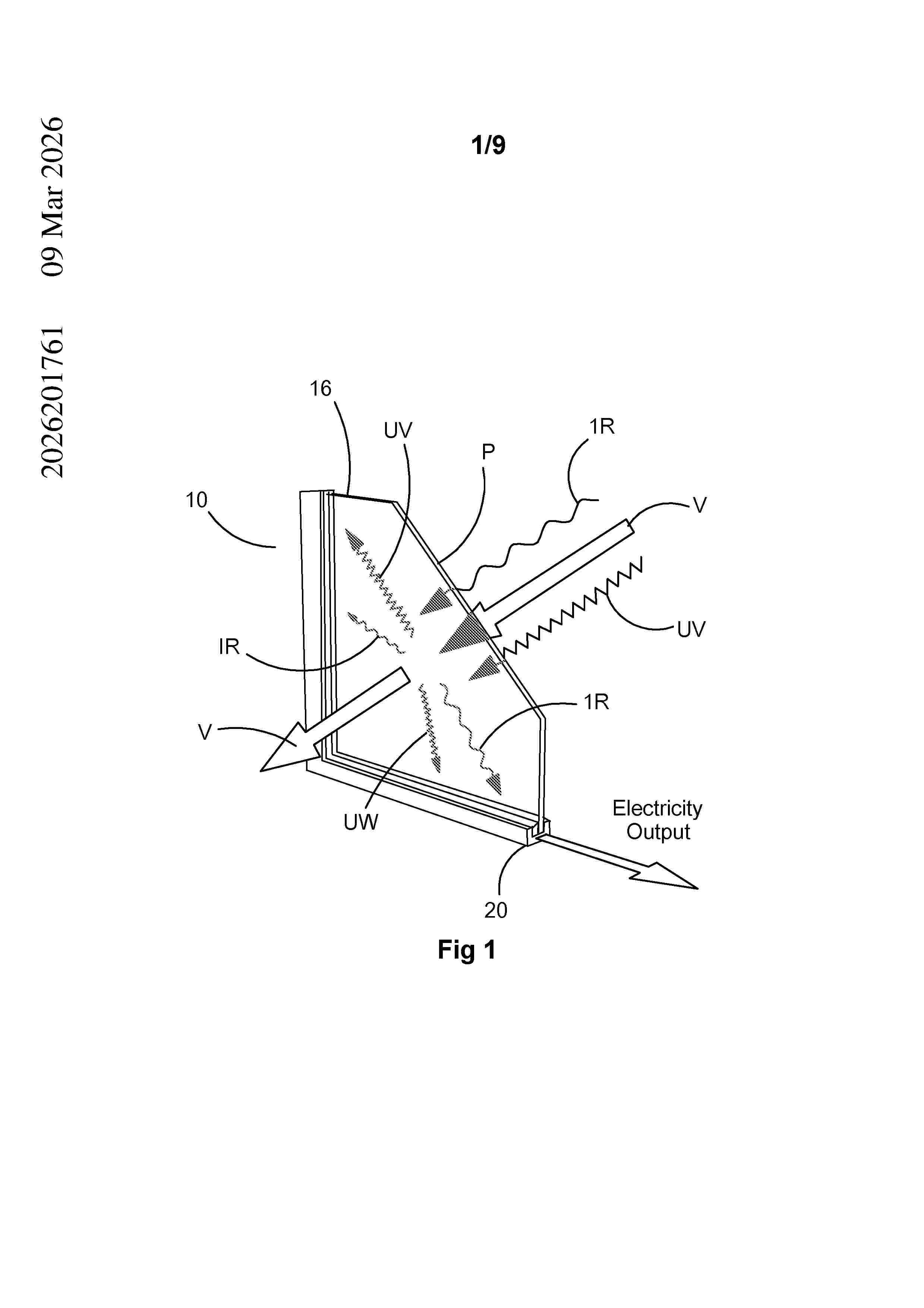
12375217_1 (GHMatters) P111329.PCT Abstract The present disclosure provides a building unit comprising first and second light transmissive panels. The first panel defines a light receiving surface. The building unit also comprises a structure supporting the panels in a spaced apart relationship to form 5 a cavity therebetween. In addition, the building unit comprises one or more photovoltaic cells disposed within the cavity adjacent the structure. The building unit also comprises an arrangement supported by the structure for re-directing non-visible wavelengths of sunlight incident on or passing through the light receiving surface in a direction generally transverse to a plane of the unit toward structure for collection by 10 the one or more photovoltaic elements. Further, the building unit comprises one or more electrically powered devices within the cavity and arranged to receive electrical power generated by the one or photovoltaic cells. Abstract ar a r
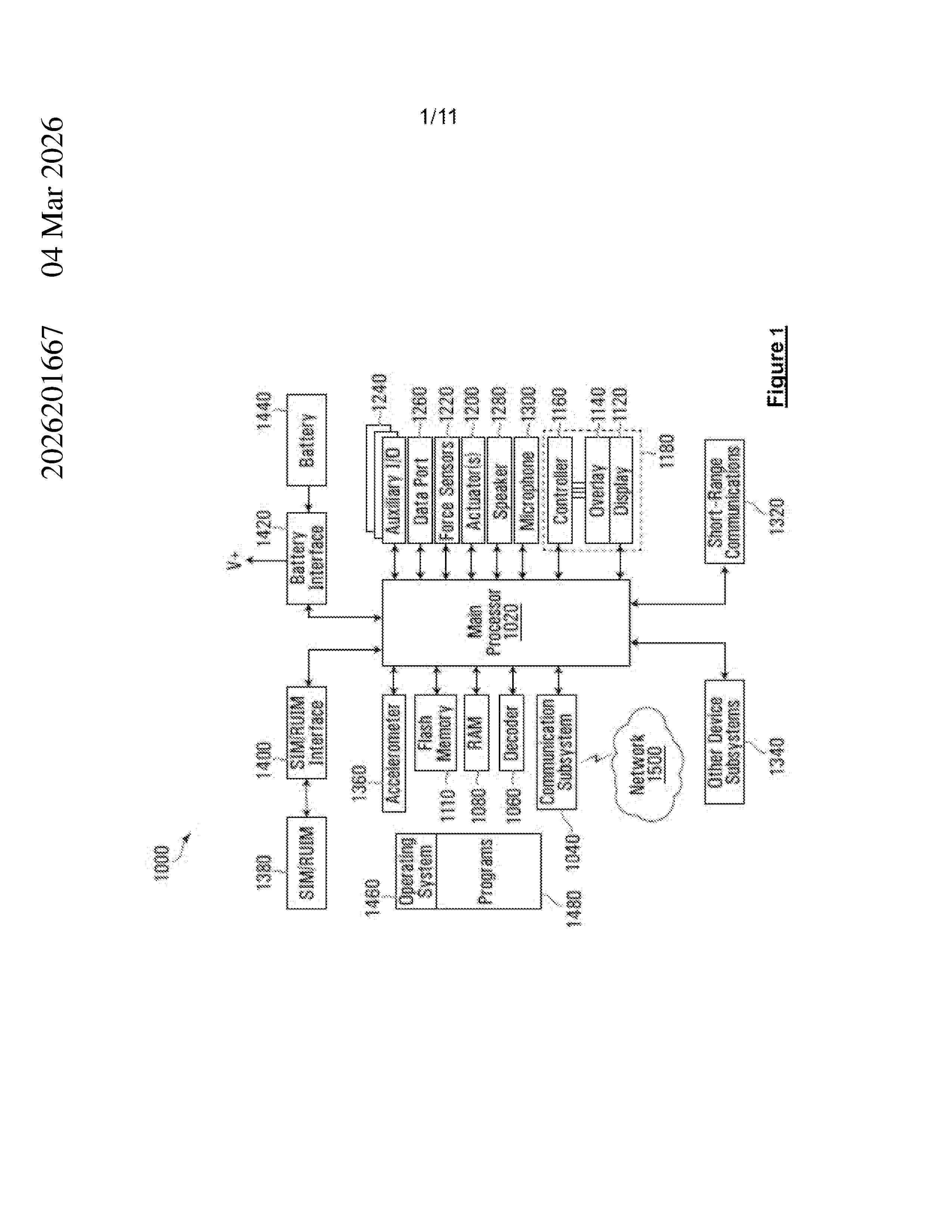
Resumen de: AU2026201667A1
WIRELESS POWERED TRANSACTION SYSTEMS AND METHODS Provided is a powered transaction system and method. The system includes a distributed blockchain application which facilitates wireless powered transactions between a buyer and a supplier, wherein the blockchain application includes at least one blockchain ledger, a wireless powered two-part blockchain currency, the two-part currency comprising a first currency and a second currency, a trust server which stores the two-part currency and fiat currency, and a first server, wherein the first server receives fiat currency from a buyer transaction device in a first transaction recorded on the at least one blockchain ledger and exchanges the fiat currency for two-part currency from the trust server, and wherein the first currency is provided to the buyer transaction device and the second currency is retained by the first server. WIRELESS POWERED TRANSACTION SYSTEMS AND METHODS ar a r
Resumen de: WO2026064616A1
A truss foundation system is disclosed for supporting a single-axis solar tracker in agrivoltaic installations. The system includes a screw anchor foundation component having an embedment end and an opposing driving end. A Y-shaped screw cap sleeves over the driving end of the screw anchor and includes a lower portion and a pair of upper portions extending at reciprocal angles relative to a vertical midline. A pair of truss legs are connected to the respective upper portions of the screw cap and extend upwardly to support the tracker structure.
Resumen de: CO2024012955A1
La presente invención se refiere a un sistema multifuncional de generación de energía eléctrica e hidrógeno verde mediante la combinación de diversas fuentes de energía renovable, como la irradiación solar, la biomasa, el hidrógeno verde, el GLP y el gas natural. Este sistema es modular y compacto, diseñado para ser eficiente y adaptable en zonas rurales o aisladas. El sistema utiliza un colector solar térmico parabólico que concentra la irradiancia solar en un módulo generador termoeléctrico, mejorado con un metamaterial de enfriamiento radiativo para optimizar el diferencial de temperatura y aumentar la eficiencia. También, incluye un quemador hexagonal híbrido, que permite la combustión de biomasa, hidrógeno, GLP y gas natural para generar calor y electricidad. Además, cuenta con un electrolizador para la producción de hidrógeno verde, que puede ser almacenado y utilizado según sea necesario. El sistema está diseñado para proporcionar un suministro de energía constante, incluso bajo condiciones de baja irradiancia solar, integrando tecnologías como un filtro óptico de luz visible y un concentrador de radiación. Esta configuración no solo mejora la eficiencia energética, sino que también promueve el uso de energías renovables, la transferencia de calor a diferentes longitudes de onda y reduce la dependencia de combustibles fósiles. Esta invención busca mejorar la calidad de vida en comunidades aisladas al proporcionarles acceso a energía l
Resumen de: WO2026063241A1
In a four-terminal tandem solar cell panel, provided is a solar cell panel in which the number of terminal boxes can be reduced to one. A solar cell panel 100 comprises: a four-terminal tandem solar cell module 110 having a bottom-side solar cell sub-module 10 and a top-side solar cell sub-module 20 which are stacked in a stacking direction; and a four-terminal terminal box 120 having a pair of bottom-side terminal bases 61 for the solar cell sub-module 10 and a pair of top-side terminal bases 62 for the solar cell sub-module 20. The solar cell module 110 has an insulating layer 8 disposed between the bottom-side solar cell sub-module 10 and the top-side solar cell sub-module 20. The terminal box 120 has an insulating isolation wall 50 disposed between the pair of bottom-side terminal bases 61 and the pair of top-side terminal bases 62.
Resumen de: WO2026061249A1
Provided in the present application is a portable photovoltaic power generation apparatus. The portable photovoltaic power generation apparatus comprises: a transmission line; a photovoltaic module, which is electrically connected to the transmission line; a changeover switch, which is arranged on the transmission line, and is used for switching the connection mode between the photovoltaic module and the transmission line, wherein the connection mode comprises series connection and/or parallel connection; and a protective member, which is arranged on the changeover switch, and is used for protecting the photovoltaic module from damage when the photovoltaic module is shaded or malfunctions. In the portable photovoltaic power generation apparatus provided by the present application, the changeover switch is provided to perform switching between series connection and parallel connection, such that rapid switching can be realized, thereby improving the switching efficiency. The photovoltaic module can be protected from damage when the photovoltaic module is shaded or malfunctions, and there is no need to provide a bypass diode on each single panel of the photovoltaic module, such that the number of bypass diodes provided is reduced, thereby lowering the costs.
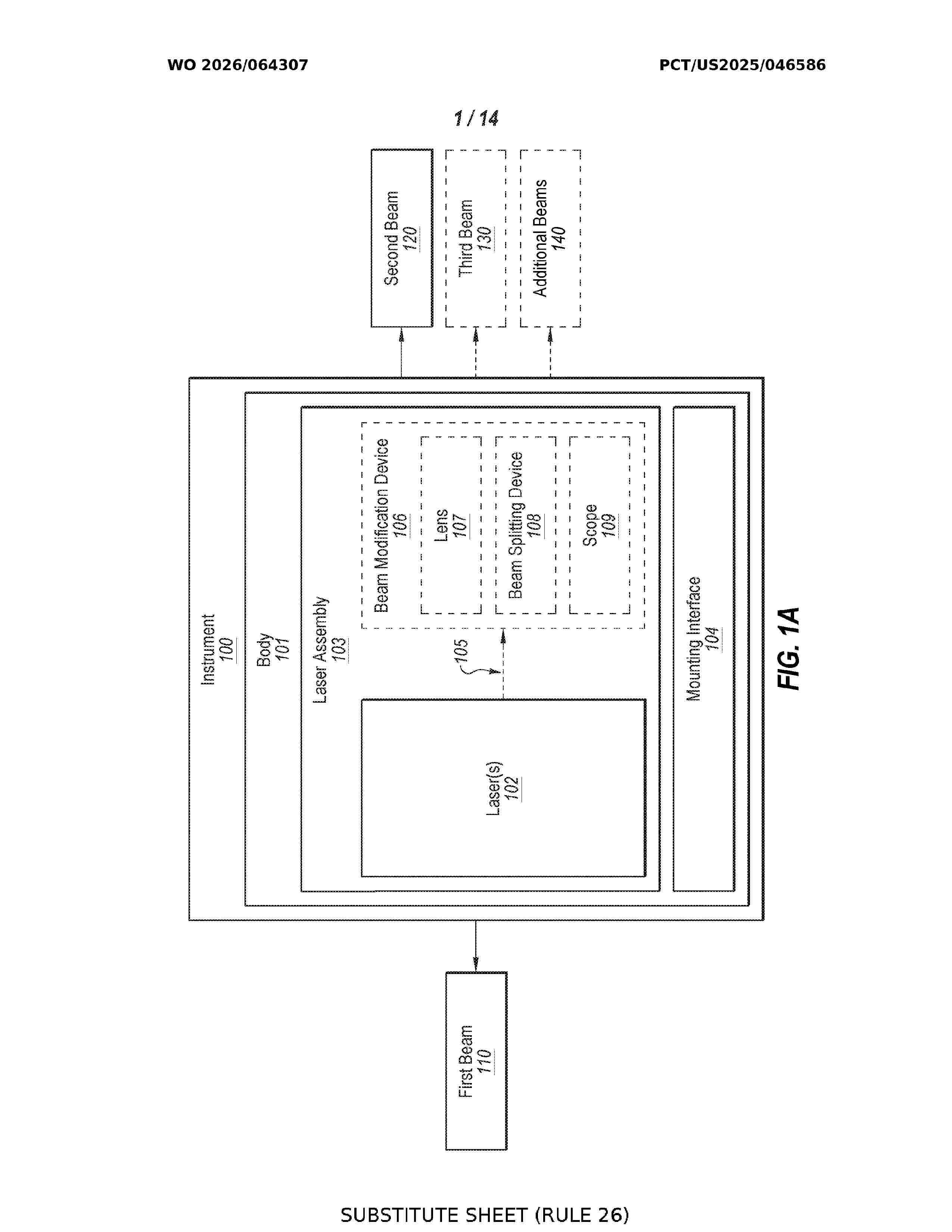
Resumen de: WO2026064307A2
An instrument for ensuring proper pile installation in photovoltaic systems (PV) may include a laser assembly configured to output a first beam in a first direction and a second beam in a second direction. The second beam may indicate the angular tolerance of a torque tube. The instrument may further include a mounting interface configured to position the laser assembly on a mounting pile.
Resumen de: WO2026064078A1
A method for testing an electrical device installed in an energy system includes: receiving an identifier and a test identification (testID) associated with the electrical device; validating the identifier and the testID; in response to determining that the electrical device is registered and communicating: setting and storing a polling rate and a posting rate of the electrical device, setting a first plurality of pre-conditions associated with a first test, and in response to determining that the first plurality of pre-conditions is met, performing the first test by: executing a first set of test commands associated with the first test, receiving responses to the first set of test commands of the electrical device, determining first test results based on the responses to the first set of test commands, storing the first test results, and determining whether the electrical device has passed the first test.
Resumen de: WO2026064086A1
A photovoltaic (PV) module mount having an integrated cable management feature, a system incorporating a PV module mount, and a method for making a PV module mount are disclosed. In one embodiment, a PV module mount may include a mounting rail configured to be secured to a PV module. The mounting rail may include a first side wall having a top edge and a bottom edge, a second side wall having a top edge and a bottom edge, a connecting structure connecting the first side wall to the second side wall, and a cable management feature configured to retain one or more electrical cables. The cable management feature may be integrally formed with at least one of the first side wall, the second side wall, and the connecting structure.
Resumen de: WO2026061239A1
The present application relates to the technical field of photovoltaic cleaning, in particular, to a portable photovoltaic cleaning apparatus, comprising a water storage tank (1), wherein a storage battery (2) is connected to a side wall of the water storage tank (1); a controller (3) is connected to an end face of the storage battery (2); a lifting and opening/closing structure (4) is connected in an inner cavity of the water storage tank (1); a cleaning structure (5) is connected to the lifting and opening/closing structure (4); water pumps (6) are symmetrically connected to side walls of the water storage tank (1); self-locking universal wheels (7) are connected at four corners of the bottom of the water storage tank (1); and a cart handle (8) is connected to a side wall of the water storage tank (1). In the present application, by means of providing the lifting and opening/closing structure (4) in the portable photovoltaic cleaning apparatus, a driving electric motor (401) in the lifting and opening/closing structure (4) is utilized to enable a cleaning roller (506) to retract by means of a transmission structure, such that the cleaning roller (506) can be retracted during transportation, thereby facilitating the transportation of a device. During transportation, a cleaning structure can be protected, and the service life of the device can be prolonged, thereby solving the problem whereby the cleaning roller (506) cannot be retracted.
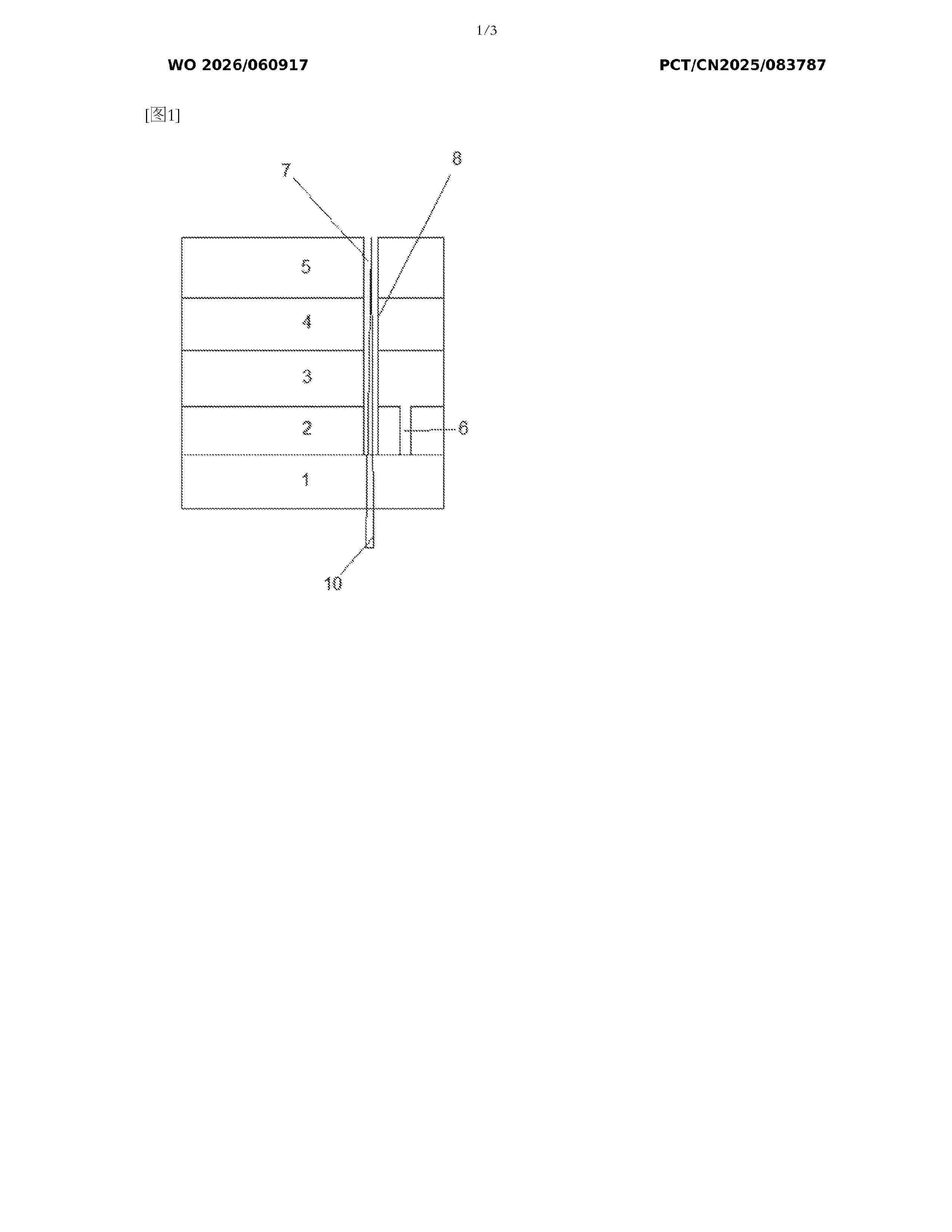
Resumen de: WO2026060917A1
Disclosed are a method for preparing a perovskite solar cell, a solar cell, and a photovoltaic system. In the method for preparing a perovskite solar cell provided by the present invention, a passivation gas is introduced into the etching region during the process of laser etching of a second etched groove and a third etched groove. The passivation gas reacts with Pb2+ in the perovskite layer to form a passivation film covering the etching position of the etched groove. During laser etching, the passivating gas is introduced to form the passivating film covering the etched portion, thus preventing the perovskite material from being exposed to a water and oxygen environment. This accelerates the aging process of the material, thereby reducing the service life and the photoelectric conversion capability of the perovskite module.
Resumen de: WO2026061442A1
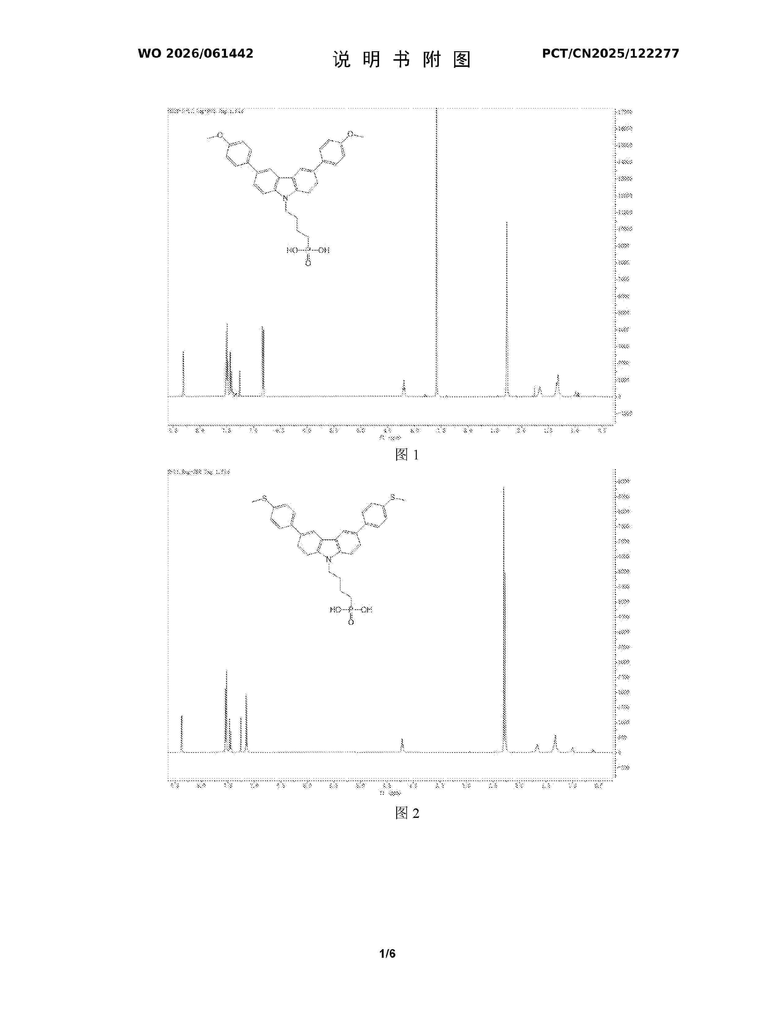
The present invention relates to the field of photovoltaic materials. The present invention provides a self-assembled hole transport material and a use thereof. The self-assembled hole transport material is a new carbazole derivative. The new carbazole derivative has a phosphonic acid anchoring group and can realize the self-assembly of a monolayer. In addition, a hydrophilic group containing an aromatic ring is introduced on one side of two benzene rings in carbazole. The hydrophilic group comprises methoxyphenyl, methylthiophenyl, cyanophenyl, formamidophenyl, or carboxyphenyl, and the hydrophilic group can effectively improve the good wettability of a perovskite precursor solution on the self-assembled monolayer and can form good complexation with a perovskite component, thereby achieving the purpose of passivating a lower interface of perovskite. In addition, the aromatic ring added to the carbazole can modulate the energy levels of self-assembled small molecules and a perovskite layer, thereby better matching the perovskite, optimizing the charge transfer efficiency of a battery, and finally achieving the effect of improving the conversion efficiency and stability of a perovskite battery.
Resumen de: DE102024127309A1
PVT-Modul mit einer photovoltaischen Zelle und einem thermischen Absorber, thermischer Absorber, Verfahren zur Herstellung eines PVT-Moduls und PVT-Anordnung mit mindestens zwei PVT-Modulen.
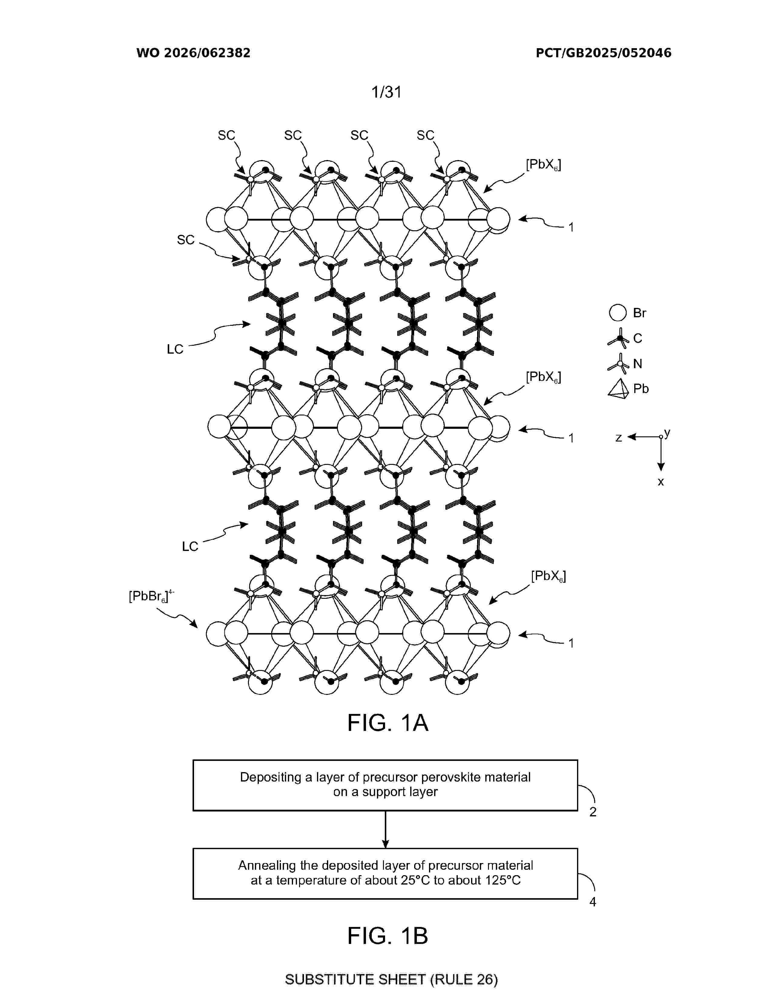
Resumen de: WO2026062382A1
A layer of perovskite material for use in an energy harvesting device, the layer having a thickness of less than 60 µm and the perovskite material comprising crystalline material of formula (LC)2(SC)n-1MnX3n+1 with a polar crystallographic point group, wherein each LC is a cation of formula A-B-C, wherein A is selected from ethyl, ethenyl, ethynyl, C1- 4 alkoxymethyl, C1-4 alkylthio, aryl, and heteroaryl, each of which is optionally substituted one or more times with fluoro and wherein the aryl and heteroaryl are optionally substituted one or more times with a substituent selected from C1-4 alkyl, C2-4 alkenyl, C2-4 alkynyl, C1-4 fluoroalkyl, C2-4 fluoroalkenyl, C2-4 fluoroalkynyl, C1-4 alkoxy, hydroxy, formyl, carboxyl and heteroaryl, B is absent or is selected from C1-6 alkylene, C2-6 alkenylene and C2-6 alkynylene, each of which is optionally substituted with fluoro, and C is -N(R1)3+ or - CR1N(R1)2N(R1)2+, wherein each R1 is independently selected from H and C1-6 alkyl, each SC is a cation selected from Cs+, N(R2)4+ and R2CN(R2)2N(R2)2 +, wherein each R2 is independently selected from H and methyl, each M is selected from Pb2+, Sn2+ and Ge2+, each X is halide, n is an integer selected from 1 to 6, and the material comprising photovoltaic and ferroelectric or piezoelectric properties.
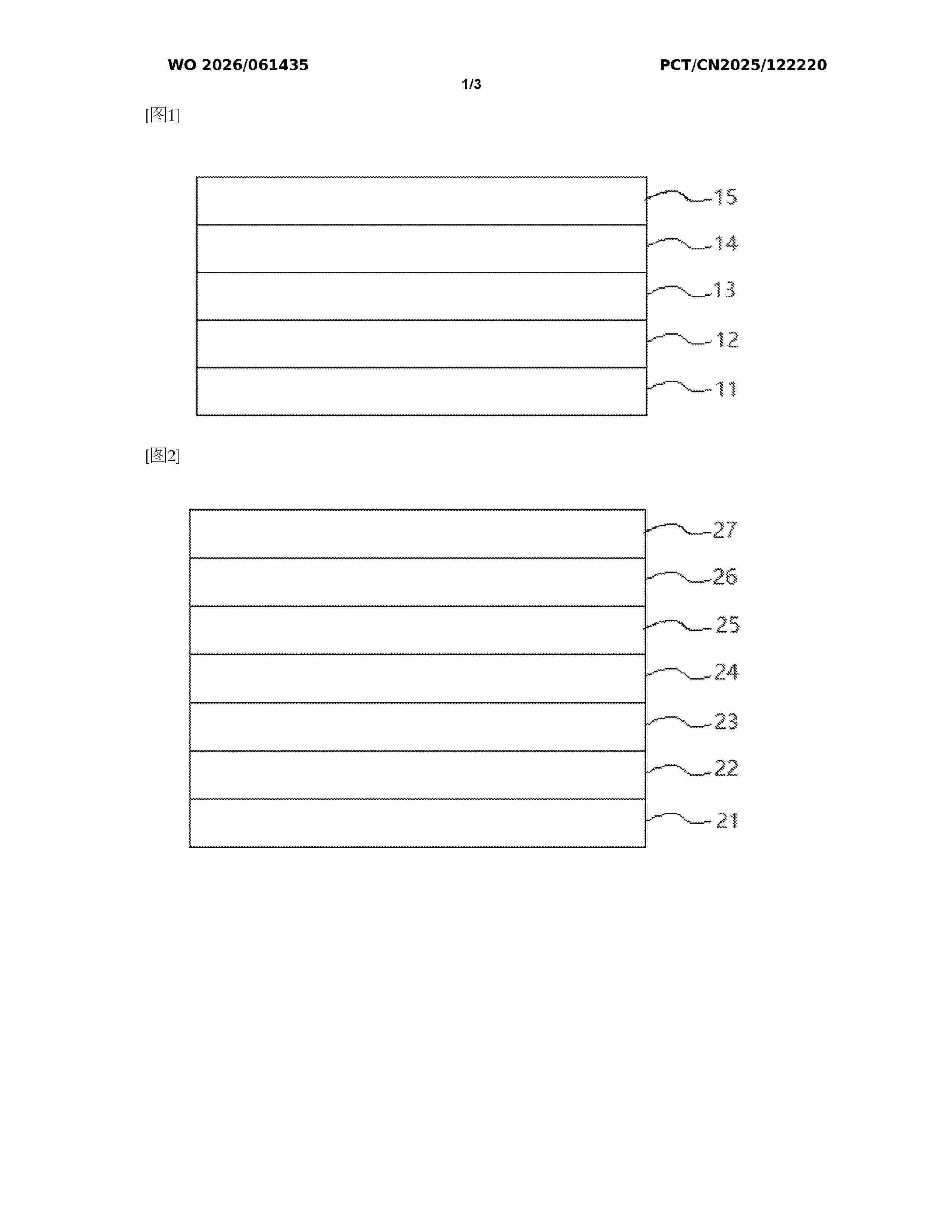
Resumen de: WO2026061435A1
The embodiments of the present application relate to the technical field of perovskite solar cells; and provide a perovskite precursor solution additive, a perovskite precursor solution, a photoelectric device, a perovskite solar cell, a photovoltaic module and a photovoltaic system. The perovskite precursor solution additive comprises one or more of an alkaline earth metal salt of a polyhydroxy aldehyde, an alkaline earth metal salt of a polyhydroxy ketone, a transition metal salt of a polyhydroxy aldehyde and a transition metal salt of a polyhydroxy ketone. As a perovskite precursor solution additive, same improves the film-forming crystallization quality of perovskite precursor solutions having different components, and also improves the film-forming crystallization quality of perovskite precursor solutions that have been subjected to different processes.
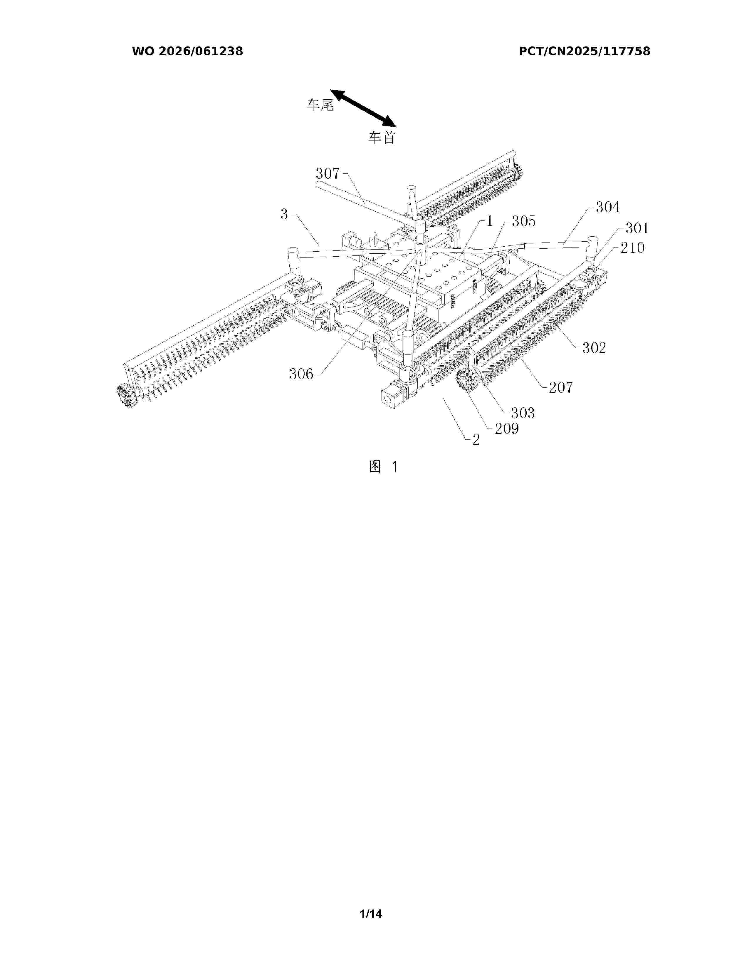
Resumen de: WO2026061238A1
A robot for photovoltaic cleaning. The robot comprises a vehicle body assembly, comprising a vehicle body part and a center-of-gravity distribution part, the vehicle body part comprising a frame; and a functional assembly, comprising a support part, an adjustment part and an action part, wherein the support part comprises side arms respectively mounted on two sides of the front end and two sides of the rear end of the frame; knuckle support frames are provided at all far ends of the side arms; and the knuckle support frames located on the two sides of the front end extend straight towards the front of a vehicle, and the two separately bend outwards by 90 degrees at the far ends. By means of changing the direction of main shafts, Mecanum wheels are at an angle that enables normal operation, thereby increasing the overall length of the robot, and also naturally improving the capability to span a gap. In this way, the need for manual back-and-forth transporting can be prevented, thereby saving time and effort, and being suitable for wider-range operations.
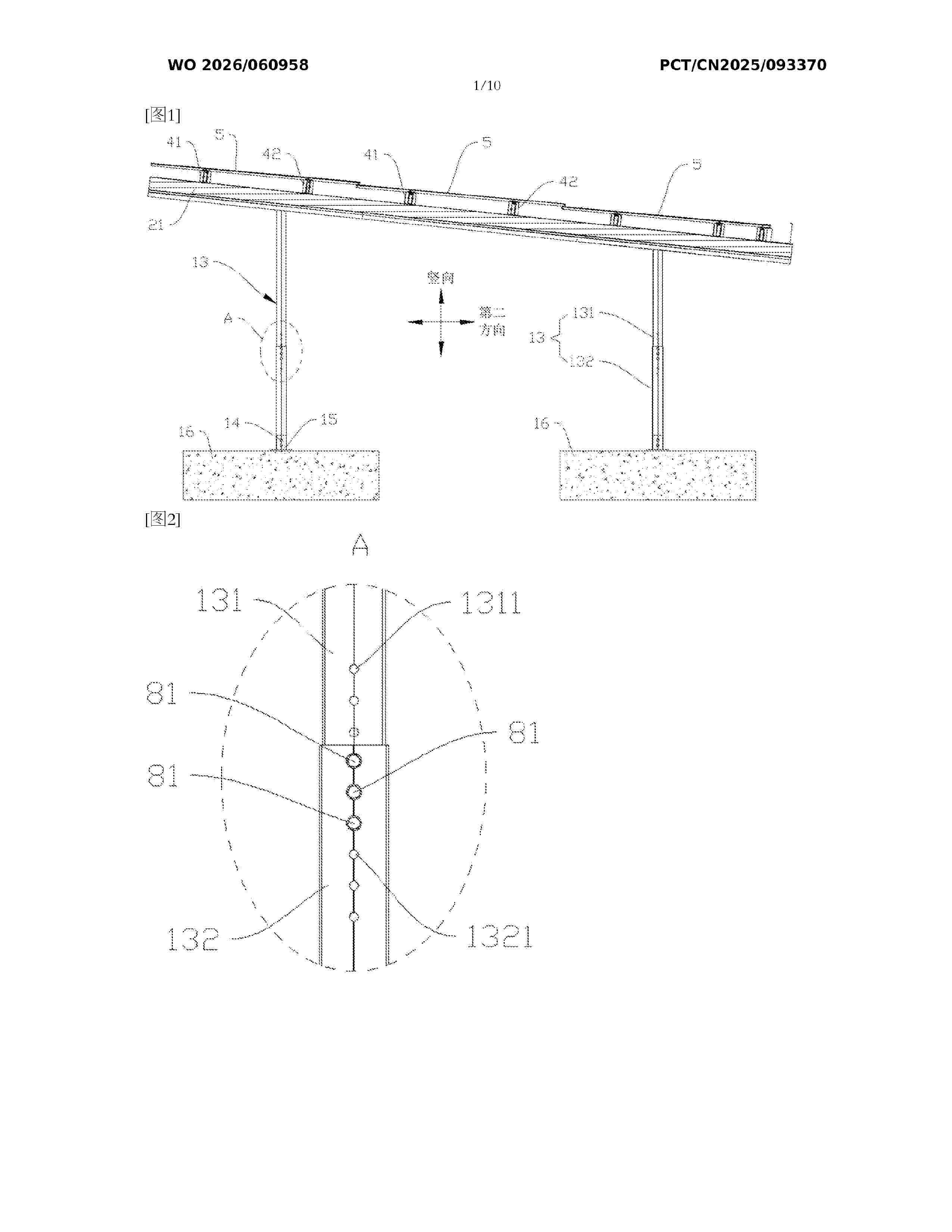
Resumen de: WO2026060958A1
Disclosed in the present application is a prefabricated household photovoltaic carport, comprising a support, the support being used for connecting to anchor bolts on the ground by means of fastening nuts; an upper end surface of the support in the vertical direction is provided with a crossbeam assembly, and the crossbeam assembly is connected to the support by means of first bolt assemblies; an upper end surface of the crossbeam assembly in the vertical direction is provided with a purlin assembly to form a grid-like structure, and the purlin assembly is connected to the crossbeam assembly by means of second bolt assemblies; a photovoltaic module is arranged on the upper end surface of the purlin assembly in the vertical direction, a pressing plate assembly is lap-jointed and pressed against one end of the photovoltaic module facing away from the purlin assembly, and the pressing plate assembly is connected to the purlin assembly by means of third bolt assemblies. The present application enables household users to complete installation and use in their own courtyards with the aid of common tools such as wrenches, without the need for professional construction teams, which is conducive to widespread adoption. Further disclosed in the present application is an installation structure for a photovoltaic module on a waterproof roof, which can seal the roof and ensure the waterproof performance of the roof.
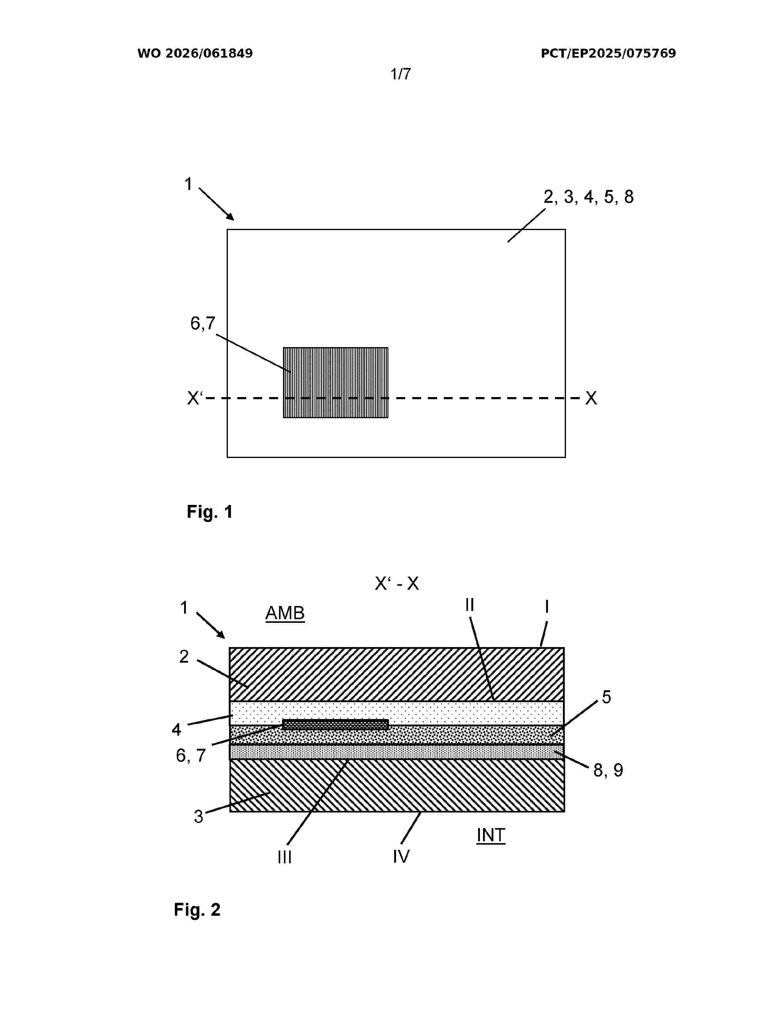
Resumen de: WO2026061849A1
The invention relates to a composite pane (1) for separating an interior (INT) from an exterior (AMB), at least comprising, in the following order, an outer pane (2) having an exterior-side surface (I) and an interior-side surface (II), a first connecting layer (4), at least one photovoltaic component (6), which has at least one colored semitransparent photovoltaic cell (7), a second connecting layer (5), and an inner pane (3) having an exterior-side surface (III) and an interior-side surface (IV). A color compensation layer (8) is formed on the interior-side relative to the at least one photovoltaic component (6), and at least in the regions of the composite pane (1) in which the at least one colored semitransparent photovoltaic cell (7) is provided in a view through the composite pane (1), the transmission through the composite pane (1) from the exterior (AMB) into the interior (INT) deviates from the mean value by a maximum of 5% points in the wavelength range of 400 nm to 780 nm.
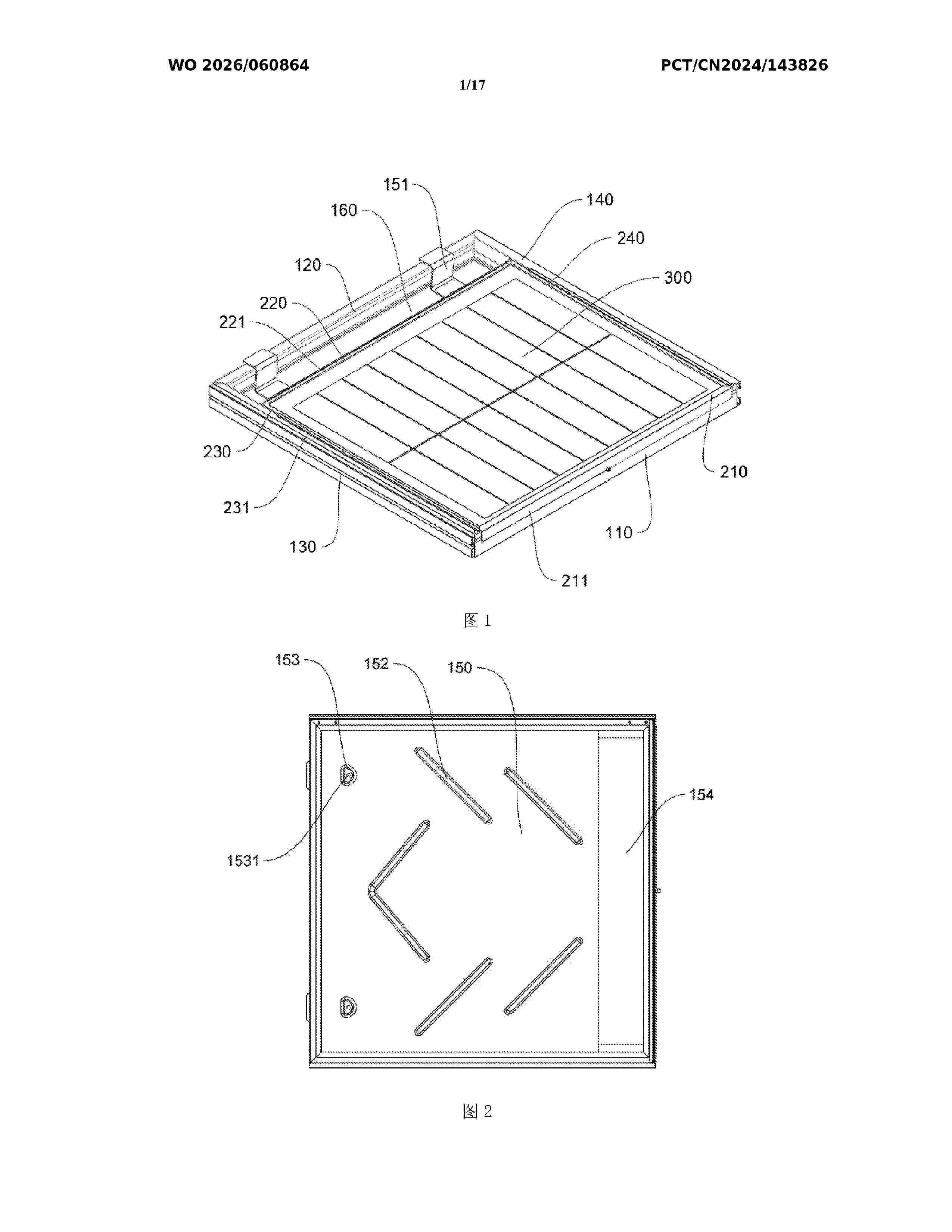
Resumen de: WO2026060864A1
A flip-type photovoltaic support, comprising: a frame, a top plate (300), a bottom plate (150) and flipping mechanism members (600), wherein the frame is formed by at least a left side wall (130), a right side wall (140), a front side wall (110) and a rear side wall (120); a first gap (160) is formed between the rear side surface of the top plate (300) and the rear side wall (120); the bottom plate (150) is embedded in the frame; a second gap (154) is formed at the position on the bottom plate (150) close to the front side wall (110); the flipping mechanism members (600) are disposed on the frame or the top plate (300) or the bottom plate (150), and are used for driving the top plate (300) to flip; at least one mounting position is provided on the top plate (300), and is used for mounting a photovoltaic power generation assembly; and the top plate (300) and the frame are of a flip-type structure. During mounting, the top plate (300) is flipped to expose a space at the bottom of the frame, so as to provide a foothold for mounting personnel or to provide a mounting space for an operation and maintenance ladder (800), thereby improving safety and comfort, and reducing the risk of micro-cracks caused by stepping on a glass power generation assembly during construction.
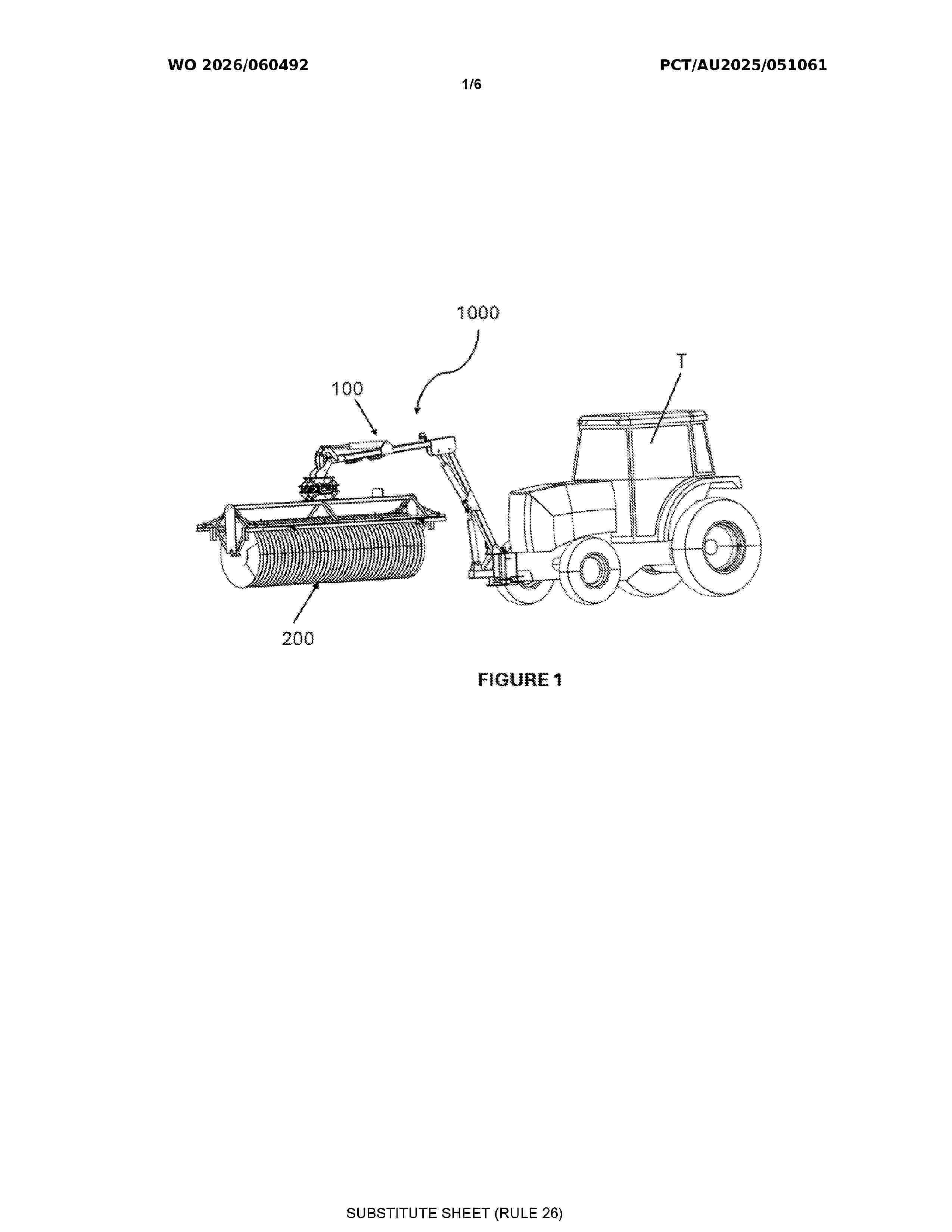
Resumen de: WO2026060492A1
A system for cleaning active surfaces of solar panels arranged obliquely relative to the ground, the system comprising: an elongate cleaning head assembly comprising a plurality of cleaning brushes extending between two ends of an elongate cleaning head frame; one or more cleaning head actuators for effecting movement of the cleaning head frame and movement of the cleaning brushes the actuators being arranged to effect said movement of the cleaning head frame and the cleaning brushes; and contour and distance detection sensors to assess relative distance between the cleaning head assembly and the active cleaning surface of the solar panels during use; an articulated supporting arm assembly comprising a plurality of supporting arms interconnecting by movable joints, wherein: a proximal end of the supporting arm assembly being configured to be movably mounted to a vehicle for allowing the supporting arm assembly to swing relative to the vehicle; and a distal end of the arm assembly being movably attached to the cleaning head assembly for allowing the elongate head assembly to be inclined relative to the distal end of the supporting arm assembly at a plurality of inclination angles wherein the articulated arm assembly comprises one or more supporting arm actuators for effecting movement of the supporting arms; and a controller comprising a memory device with executable instructions to control movement of the cleaning head assembly and the supporting arm assembly by actuating one
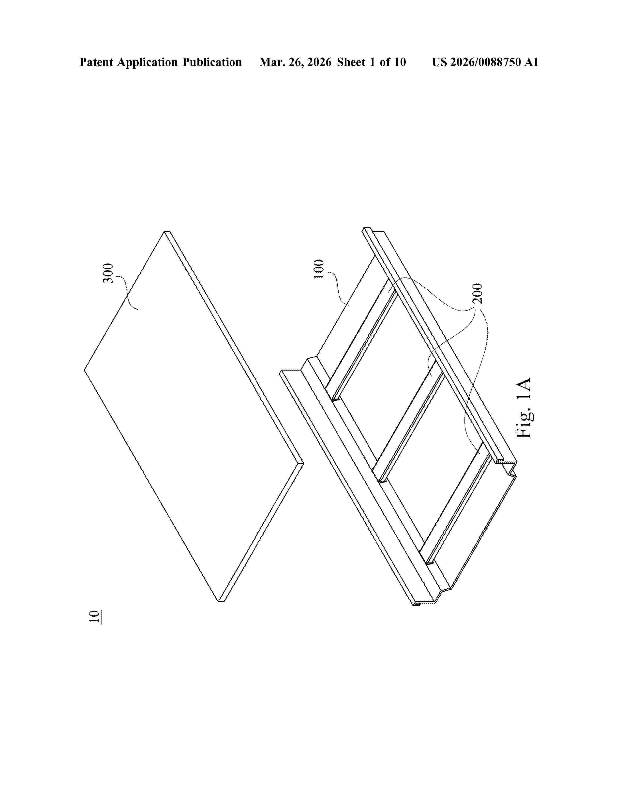
Resumen de: US20260088750A1
A photovoltaic system includes a sheet, a bracket, and a photovoltaic panel. The sheet has a base board and two side walls. The two side walls are opposite to each other and connected to the base board. The base board and the two side walls form an accommodating space. The bracket is in the accommodating space. The bracket includes a main portion, a first side portion, and a second side portion. The first side portion extends from a first side of the main portion along one of the two side walls and is coupled to the one of the two side walls. The second side portion extends from a second side of the main portion. The first side is adjacent to the second side. The photovoltaic panel is in the accommodating space and over the main portion of the bracket.
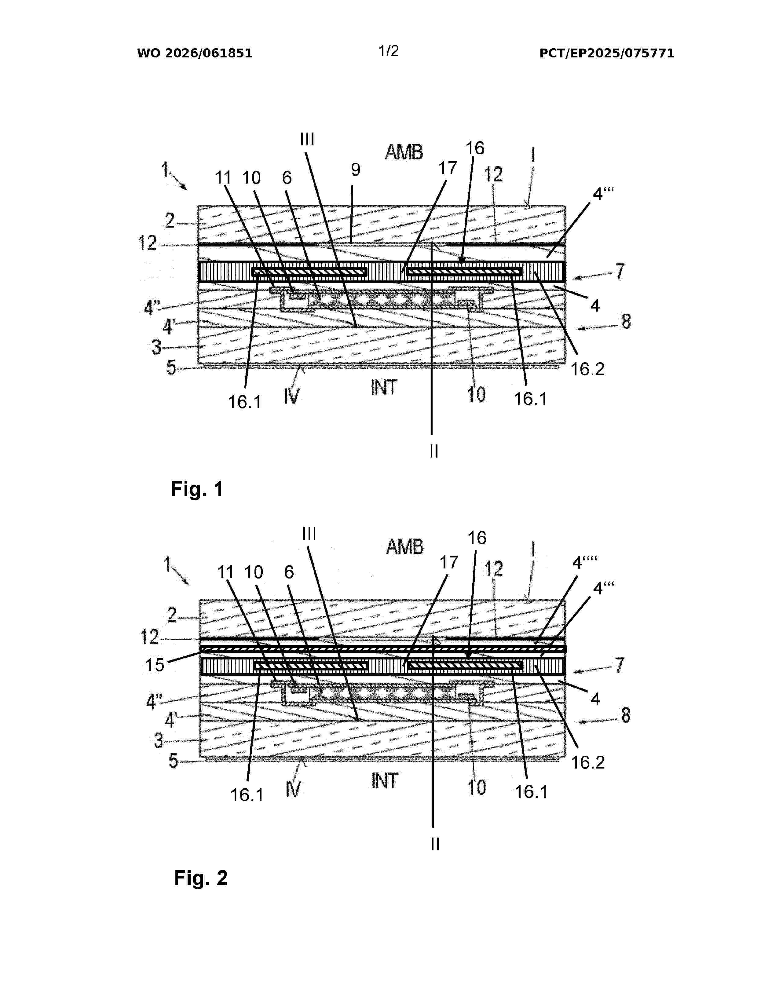
Resumen de: WO2026061851A1
The invention relates to a composite pane (1) for separating an interior from an exterior. The composite pane comprises an outer pane (2) and an inner pane (3) which are firmly bonded to one another by at least one thermoplastic interlayer (4', 4', 4''). An electrically switchable mirror element (6, 13) is arranged between the outer pane (2) and the inner pane (3), at least one photovoltaic component (16) being arranged on the exterior side of the mirror element (6, 13). The photovoltaic component (16) has a light transmission of at least 10%. Furthermore, the photovoltaic component (16) comprises a plurality of photovoltaic cells (16.1) which are electrically connected to one another, the photovoltaic cells (16.1) being arranged adjacent to one another and/or a cell gap (17) being formed between neighbouring photovoltaic cells (16.1).
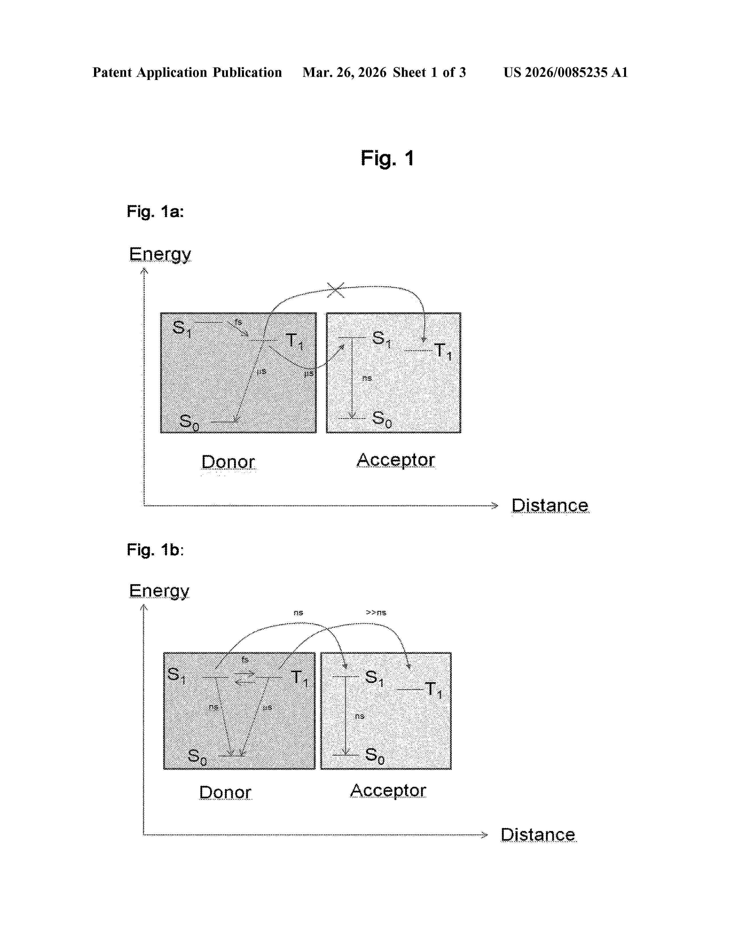
Resumen de: US20260085235A1
The present invention relates to organic light-emitting devices comprising (a) an anode, (i) a cathode, and (e) an emitting layer between the anode and cathode, comprising 2 to 40% by weight of a triplet emitter X having a difference of the singlet energy (ES1(X)) and the triplet energy (ET1(X)) of less than or equal to 0.4 eV Δ(ES1(X))−(ET1(X))≤0.4 eV, 0.05 to 5.0% by weight of a fluorescent emitter Y and 55 to 97.95% by weight of a host compound(s), wherein the amount of the triplet emitter X, the fluorescent emitter Y and the host compound(s) adds up to a total of 100% by weight and the singlet energy of the triplet emitter X (ES1(X)) is greater than the singlet energy of the fluorescent emitter Y (ES1(Y)) (ES1(X))>ES1(Y). By doping, for example, an emitting layer containing a luminescent organometallic complex having a small S1-T1 splitting, with a fluorescent emitter the emission decay time can significantly be shortened without sacrificing external quantum efficiency (EQE) because of very efficient energy transfer.
Resumen de: US20260088757A1
The invention discloses an IV detection mechanism for 0BB silicon wafers, including two detection modules, both comprise a UVW base, a gold wire row test frame and a silver row test frame; the gold wire row test frame and the silver row test frame respectively move on the UVW base along the vertical direction; gold wires are installed on the gold wire row and silver rows are installed on the silver row test frame; the two detection modules move independently. In the IV inspection mechanism for 0BB silicon wafers, the double half-cells independently carry out 0BB IV inspection, so that both sides can independently lift up and down, and correction alignment can be performed in the UVW direction, so that the gold wires and silver rows are accurately aligned with the grid lines on the half-cell, the inspection efficiency is improved, and the productivity is increased.
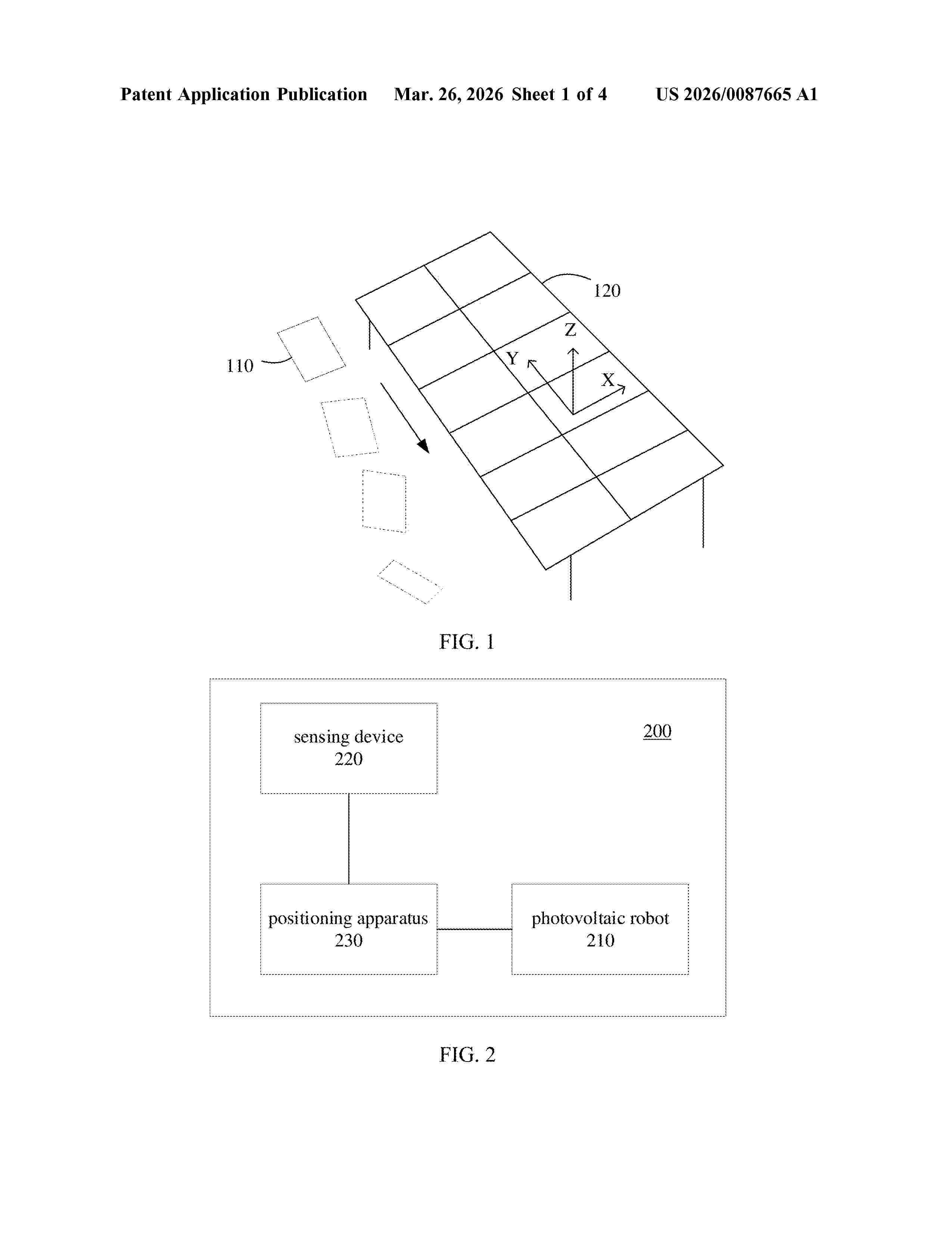
Resumen de: US20260087665A1
A positioning method, apparatus and system for a photovoltaic robot is disclosed. The method comprises: obtaining three-dimensional point cloud data of the photovoltaic bracket, wherein the three-dimensional point cloud data is obtained through a sensing device; determining a target straight line based on the three-dimensional point cloud data, wherein the target straight line comprises a straight line where a target structure of the photovoltaic bracket is located, and the target straight line is located in the plane where the photovoltaic bracket is located; determining the position information based on a first rotation matrix between a first coordinate system of the sensing device and a second coordinate system of the photovoltaic robot, as well as the target straight line; wherein the position information indicates a relative position relationship between the photovoltaic robot and the target structure. Thus, the photovoltaic robot is positioned and its abnormal pose could be detected in time.
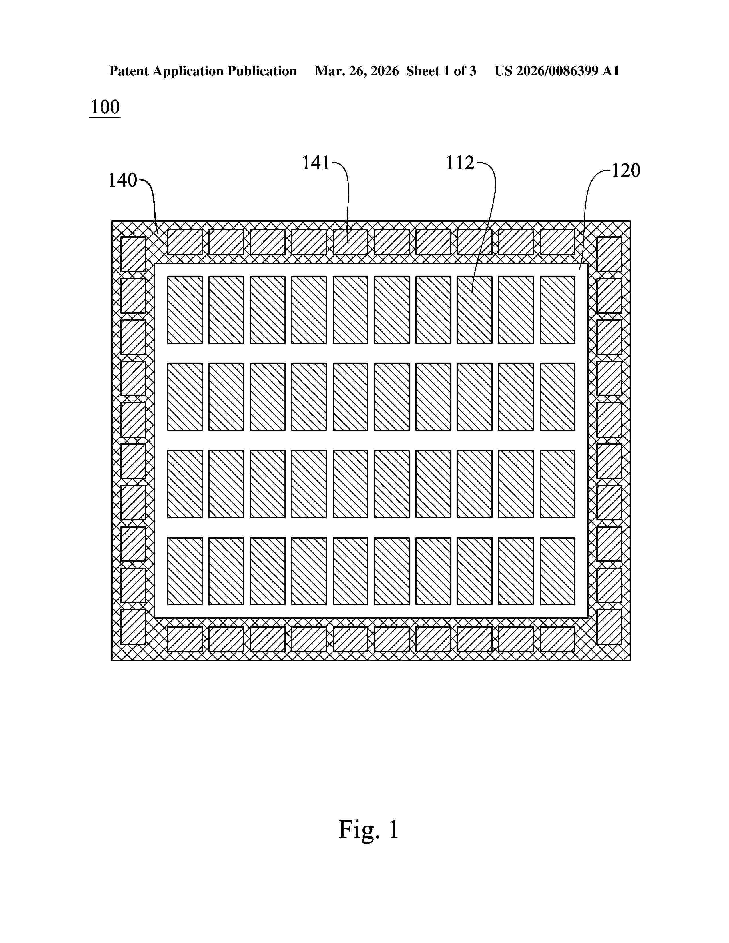
Resumen de: US20260086399A1
A self-powered display device includes a solar module and a display panel. The solar module has a first surface and a second surface opposite to each other, and includes a polymer layer, a plurality of solar cells and a plurality of opaque patterns. The solar cells are electrically connected to each other and embedded in the polymer layer at intervals. The opaque patterns are embedded in the polymer layer, wherein projections of the opaque patterns on the first surface are respectively located between projections of the solar cells on the first surface. The display panel is disposed on the first surface of the solar module. The solar module is configured to receive the light from the first surface and the second surface.
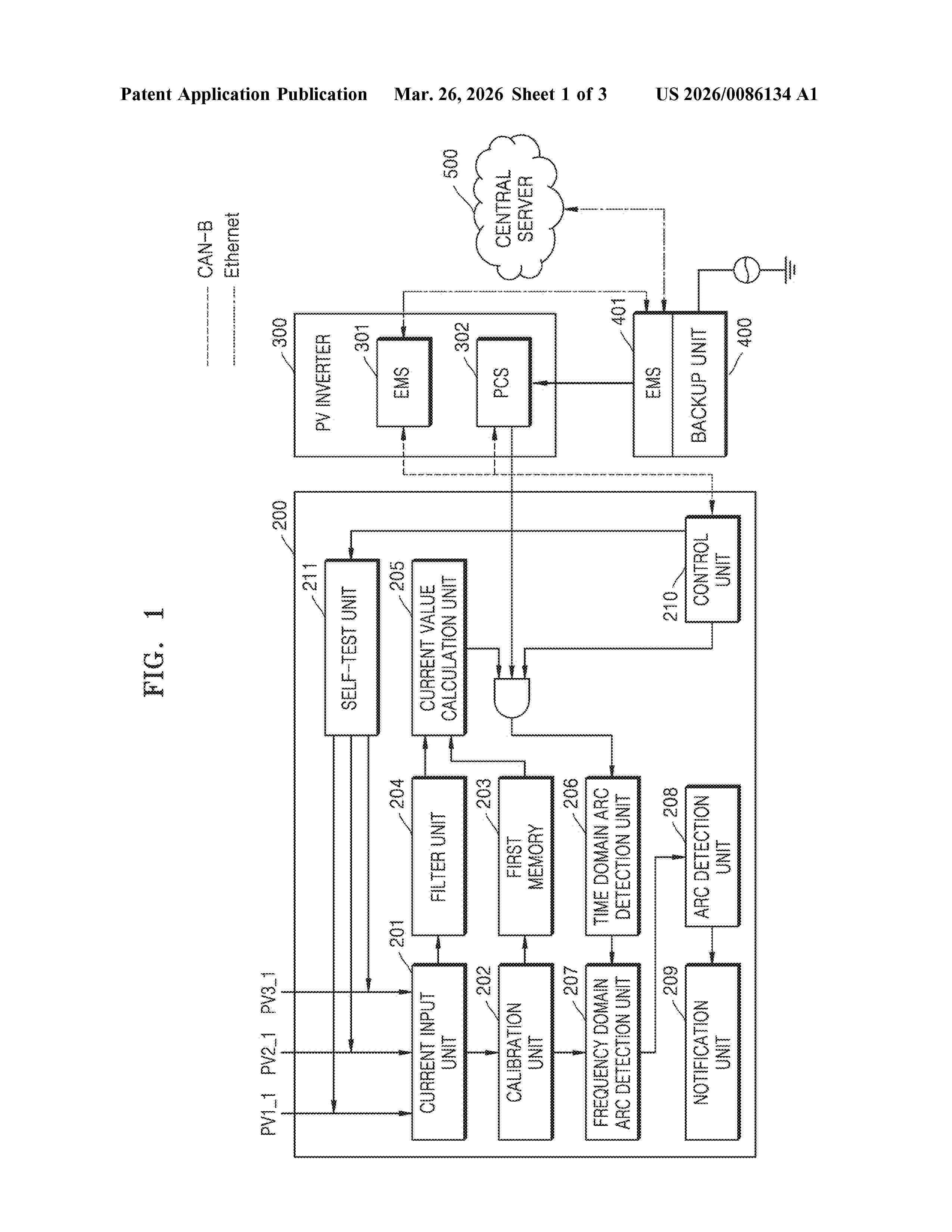
Resumen de: US20260086134A1
The disclosure relates to an arc fault circuit interrupt capable of detecting an arc fault and a method of controlling the device. The arc fault circuit interrupt according to the disclosure is shipped in a factory reset state in which all functions are initialized after a test to check for functional abnormalities, and when receiving an update instruction from an authorized administrator after being installed in the field, receives an update file from a management device such as an energy management system to proceed with a firmware update and activates an arc fault detection function, thereby having the effect of preemptively preventing unauthorized copying of the arc fault circuit interrupt.
Resumen de: US20260085895A1
A thermal battery includes a heat sink material that remains solid across an operating temperature range (i.e., for all operating modes) of the battery, and a heat conductive material in direct heat transfer relationship with the solid heat sink material. The heat conductive material has a melting point below that of the heat sink material so that in use the heat conductive material is a fluid, for example molten when the heat conductive material is a metal, in the operating temperature range of the battery.
Resumen de: US20260085708A1
A blind rivet retaining clip includes a clip base, a blind rivet aperture, a grounding tab, and a blind rivet retention tab. The clip base is configured to interface with a first side of a solar module frame. The blind rivet aperture extends through the clip base. The grounding tab extends out from a first side surface of the clip base, and the blind rivet retention tab extends out from a second, opposite side surface of the clip base and adjacent to the blind rivet aperture. The blind rivet retention tab is configured to engage a blind rivet inserted through the blind rivet aperture. The grounding tab is configured to enable an electrical grounding function at the solar module frame when the blind rivet is inserted through the blind rivet aperture and when the blind rivet is set at the blind rivet aperture.
Resumen de: US20260084984A1
A distillation and electricity generation system and method includes a first cooling section, a condenser section and a second cooling section. A first thermoelectric section includes one or more first thermoelectric modules interposed between the first cooling section and the condenser section. Each first thermoelectric module has a cold side in contact with the first cooling section and a hot side in contact with the condenser section. A second thermoelectric section includes one or more second thermoelectric modules interposed between the second cooling section and the condenser section. Each second thermoelectric module has a cold side in contact with the second cooling section and a hot side in contact with the condenser section. An electrical outlet is coupled to the first thermoelectric module(s), or the second thermoelectric module(s), or both the first and second thermoelectric modules
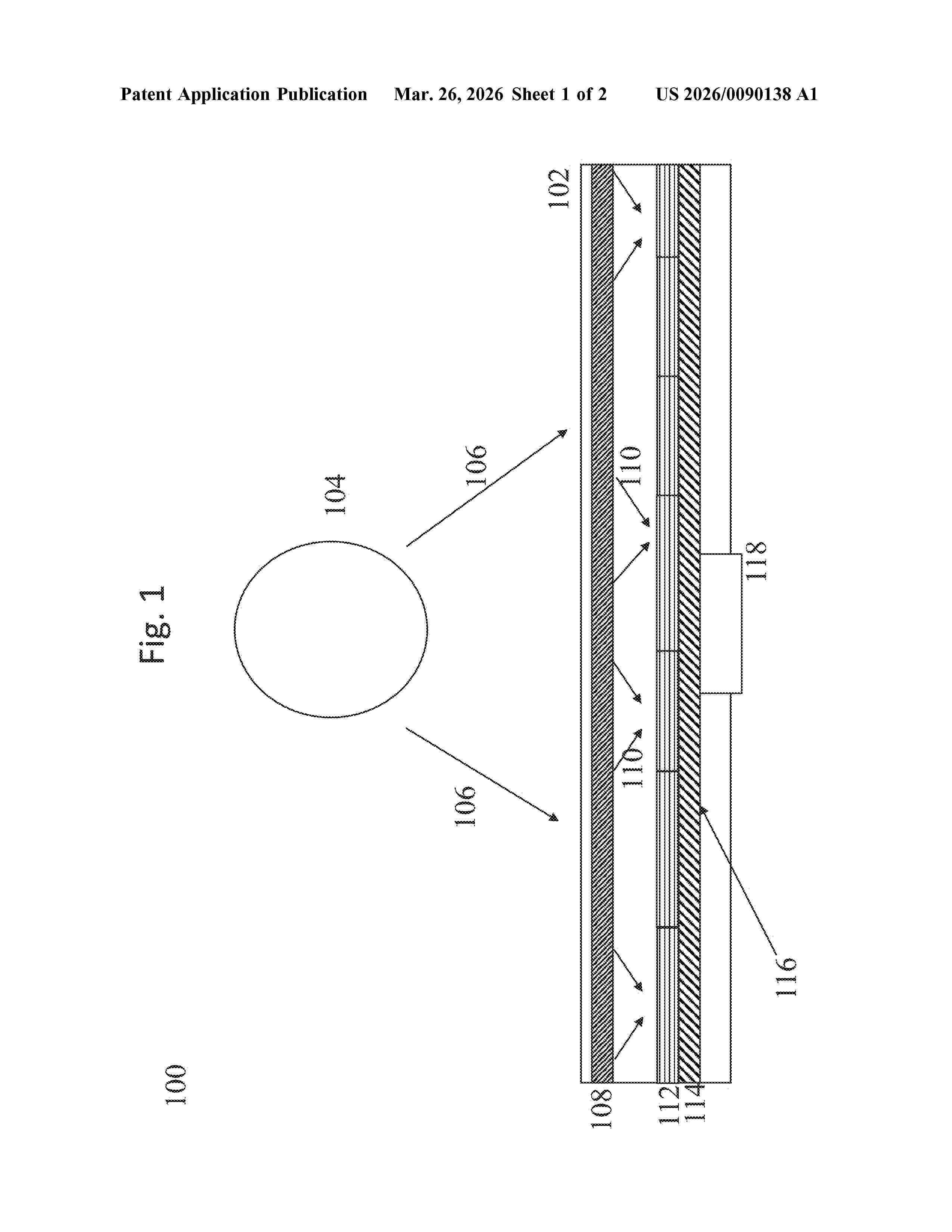
Resumen de: US20260090138A1
According to at least one exemplary embodiment an empyreal reaper may be provided. The empyreal reaper may include a packaging, one or more mirrors contained within the packaging which concentrate photonic energy from a photonic light source into focused light, one or more gain mediums which receive, on one or more absorption faces, the photonic energy concentrated by the one or more mirrors, and/or a photoelectric material which receives photonic energy from the one or more gain mediums and converts the photonic energy into electrical energy.
Resumen de: US20260090134A1
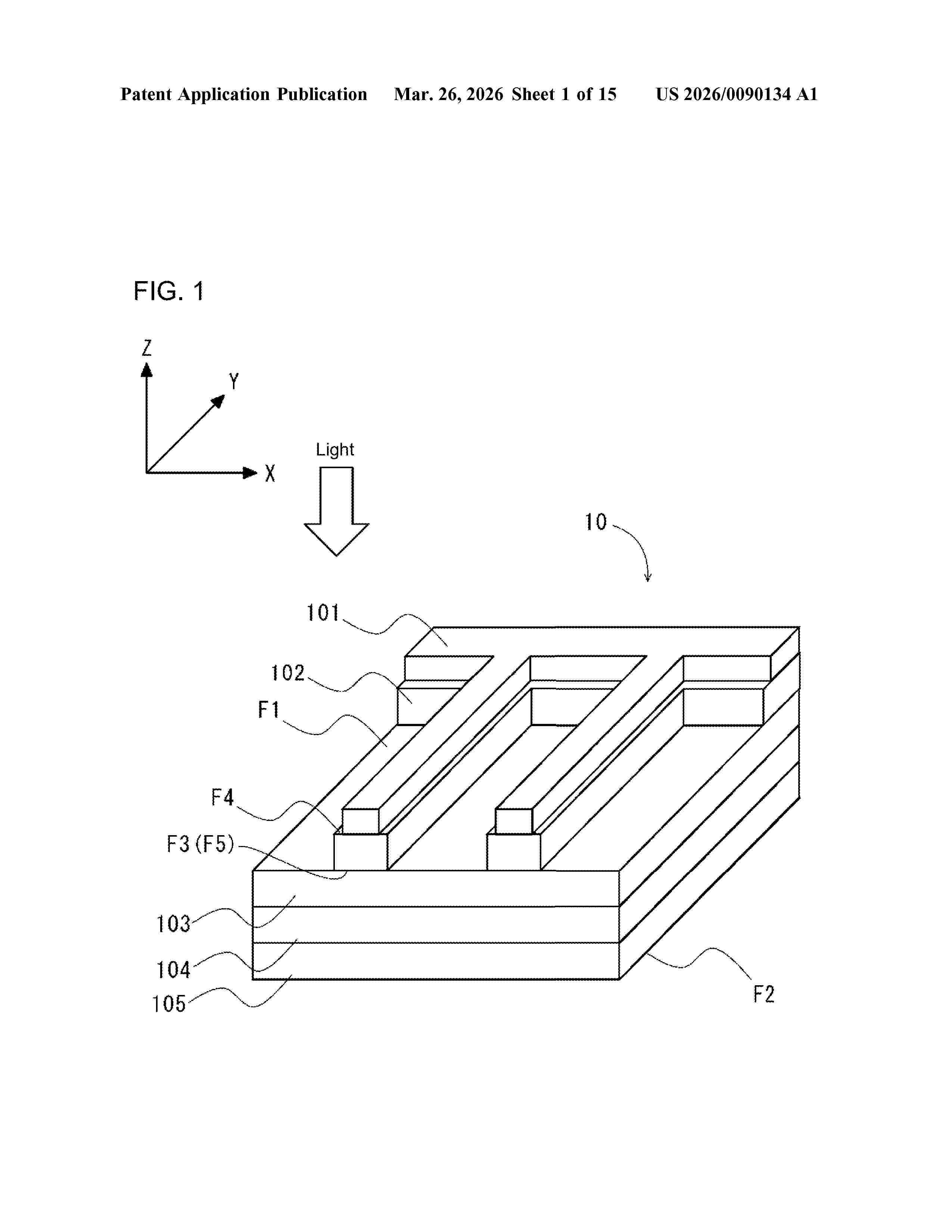
A solar cell device includes a solar cell unit, an electrode, and a first diffusion reducer. The solar cell unit includes a light-receiving surface. The first diffusion reducer is located between the solar cell unit and the electrode. The first diffusion reducer includes a first surface on the light-receiving surface and a second surface on the electrode. In a plan view of the light-receiving surface, the first diffusion reducer is located in an area other than at least part of an area not overlapping the electrode.
Resumen de: US20260090139A1
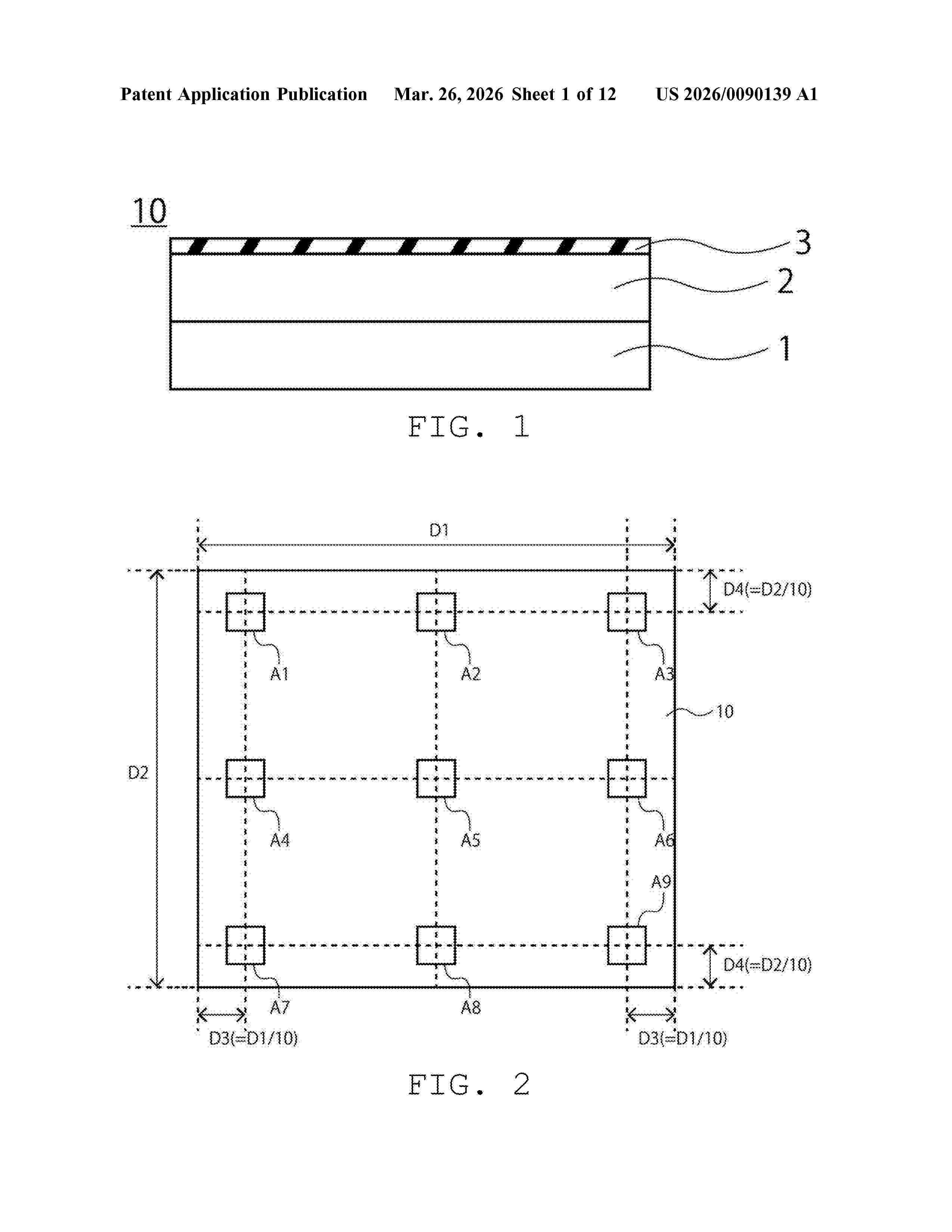
A laminated body according to an embodiment includes a substrate, a transparent electrode provided on the substrate and an insulating film provided on the transparent electrode. The insulating film covers 50% or more and 100% or less of a surface of the transparent electrode on the opposite side of the substrate. The insulating film has a thinner thickness of a thickness of the substrate.
Resumen de: US20260090130A1
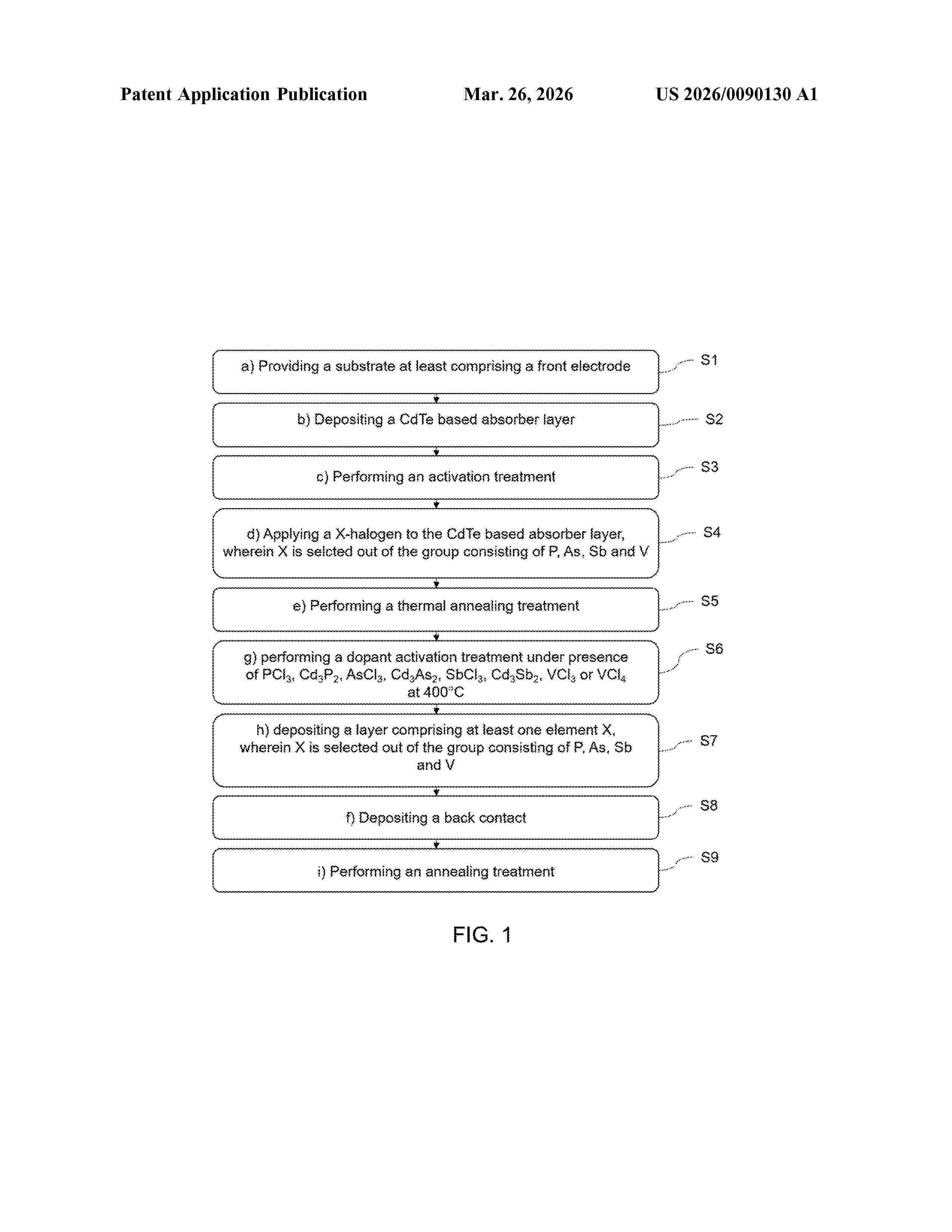
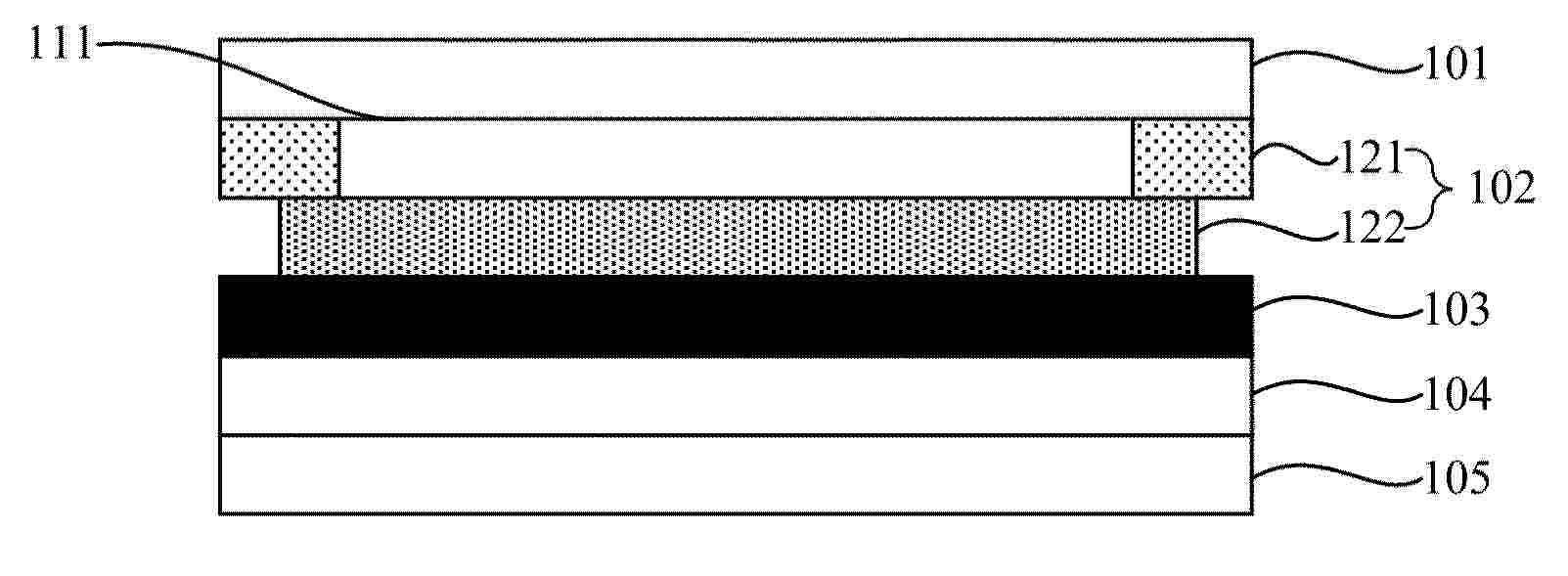
A method for manufacturing a copper-free CdTe based thin film solar cell device, comprising the following steps: a) providing a substrate at least comprising a front electrode, b) depositing a CdTe based absorber layer, c) performing an activation treatment, d) applying a X-halogen to the CdTe based absorber layer, wherein X is selected out of a group consisting of P, As, Sb and V; e) performing a thermal treatment after step d) and f) depositing a back contact, characterized in that, the thermal treatment in step e) is performed before step f) and at temperatures in the range of 40° C. to 120° C. in inert atmosphere or vacuum for a duration in the range of 10 minutes to 60 minutes.
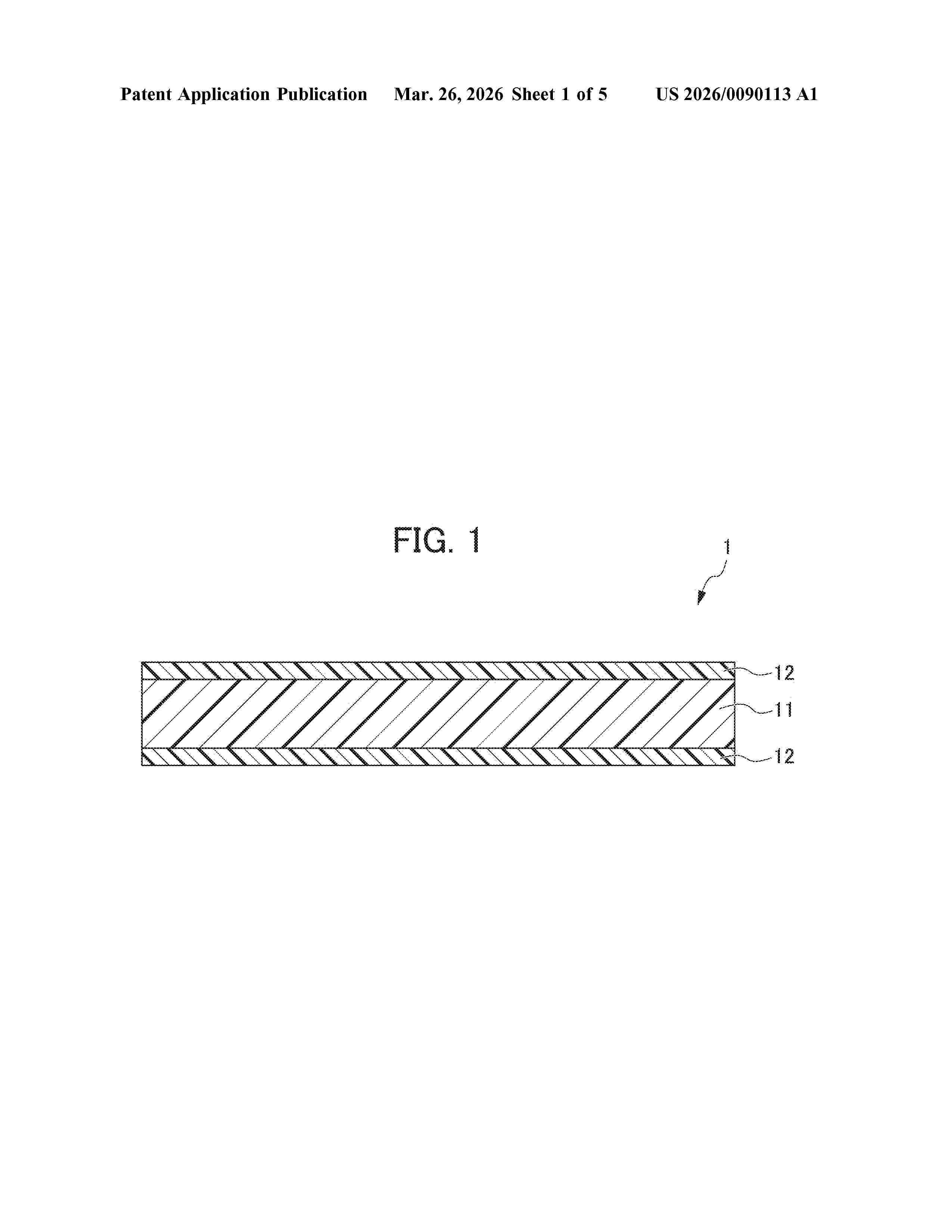
Resumen de: US20260090113A1
To provide a sealing material sheet for a solar-cell module that has high productivity without performing crosslinking processing, and has a high tensile shear adhesion force at normal temperature at a high level in addition to heat resistance and molding characteristics. A sealing material sheet is a multi-layer sheet using a polyethylene-based resin as a base resin, a core layer has a density of 0.880 g/cm3 to 0.895 g/cm3 and a melting point of 70° C. or higher, a skin layer has a density of 0.880 g/cm3 to 0.910 g/cm3 and a melting point of 90° C. or lower and contains a silane-modified polyethylene-based resin, a weight average molecular weight of the silane-modified polyethylene-based resin contained in the skin layer 11 in terms of polystyrene is 70000 to 120000, and a polymerized silane amount of the skin layer in the whole resin component is 300 ppm to 2000 ppm.
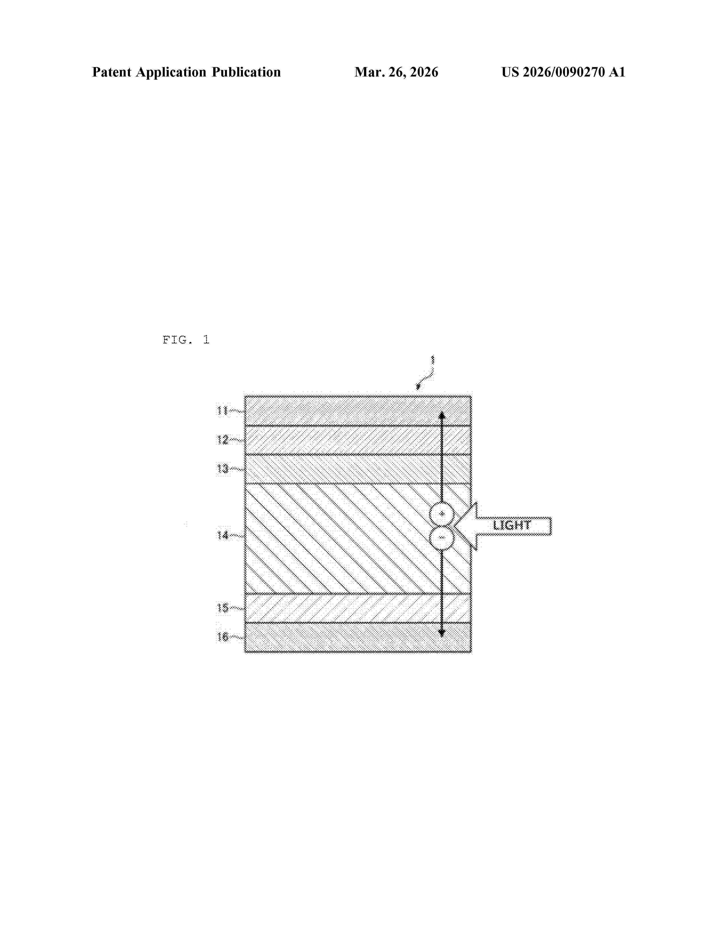
Resumen de: US20260090270A1
Provided is an organic electronic element that has an improved hole transport ability and a compound that is used in the organic electronic element and that can improve the hole transport ability thereof. The organic electronic element includes a first electrode, a second electrode and an organic layer disposed between the first electrode and the second electrode. The organic layer includes a hole transport layer and a hole transport promoting layer containing a compound having a partial structure represented by the following formula (1), or includes a layer comprising a mixture of a hole transport material and the compound having the partial structure represented by formula (1), and the organic electronic element includes a light-receiving layer:(wherein * represents a bond, and formula (1) forms a cyclic imide structure).
Resumen de: US20260090257A1
A display device includes: a display panel having a first area, a second area spaced apart from the first area in a first direction, and a bending area between the first area and the second area; a polarization layer in the first area on the display panel; and a bending protection layer on the display panel and including: a pre-formed bending protection layer spaced apart from the polarization layer in the first direction; a first post-formed bending protection layer between the polarization layer and the pre-formed bending protection layer; and a second post-formed bending protection layer spaced apart from the first post-formed bending protection layer with the pre-formed bending protection layer interposed therebetween.
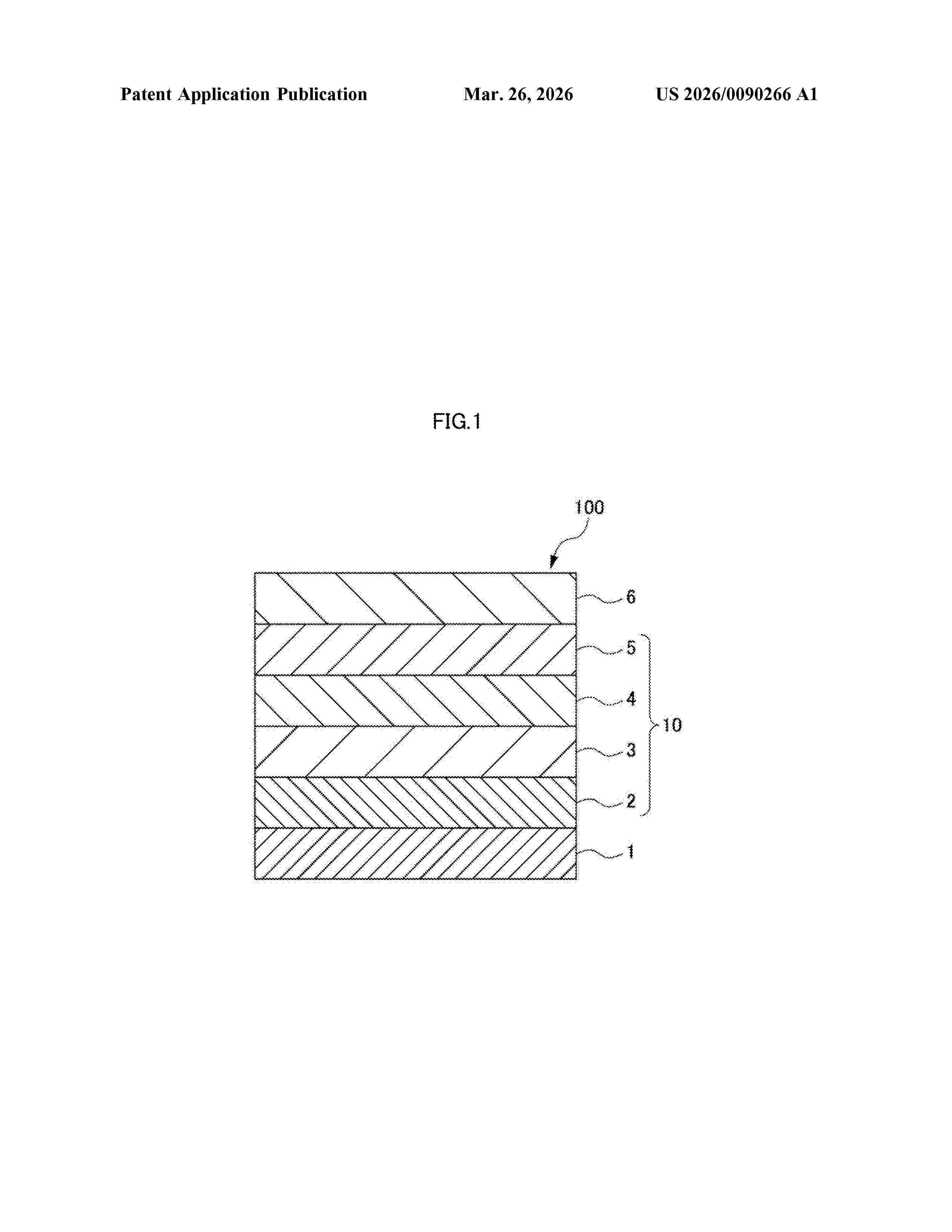
Resumen de: US20260090266A1
Provided are a photoelectric conversion element and an imaging element which are excellent in response speed and exhibit a high external quantum yield, and a photoelectric conversion element material that contributes to production of these elements. An imaging photoelectric conversion element (100) includes a layer containing a photoelectric conversion element material represented by formula (1) below, where EWG represents an electron-withdrawing group, L represents an aromatic hydrocarbon group having 6 to 30 carbon atoms, n represents 1 to 8, k represents 0 to 2, and p represents 1 to 8, where p is 1 if k is 0.
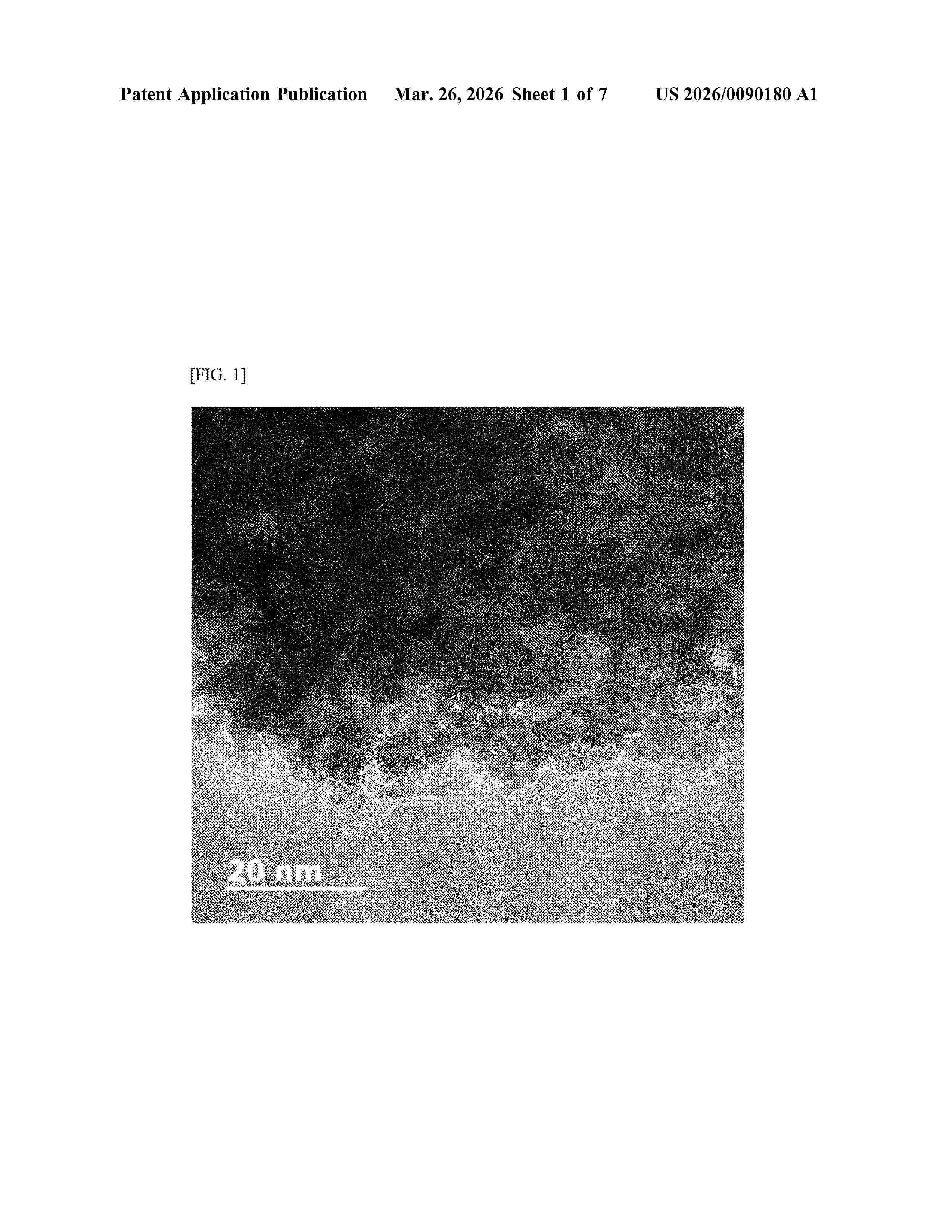
Resumen de: US20260090180A1
The present invention relates to a coating agent for forming an electron transport layer (or electron transfer layer), wherein surface-modified metal oxide nanoparticles prepared in the form of a dispersion solution are provided as the coating agent, and relates to an inverted perovskite in which an electron transport layer is formed using the same.
Resumen de: US20260090030A1
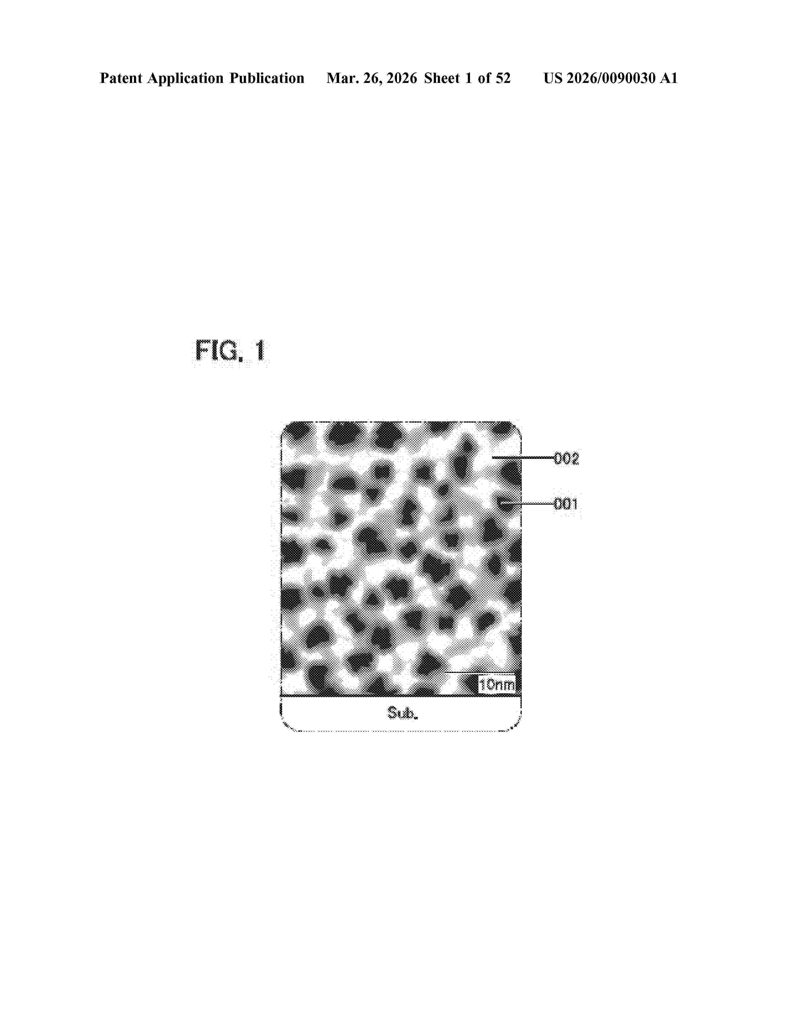
A novel material and a transistor including the novel material are provided. One embodiment of the present invention is a composite oxide including at least two regions. One of the regions includes In, Zn and an element M1 (the element M1 is one or more of Al, Ga, Si, B, Y, Ti, Fe, Ni, Ge, Zr, Mo, La, Ce, Nd, Hf, Ta, W, Mg, V, Be, and Cu) and the other of the regions includes In, Zn, and an element M2 (the element M2 is one or more of Al, Ga, Si, B, Y, Ti, Fe, Ni, Ge, Zr, Mo, La, Ce, Nd, Hf, Ta, W, Mg, V, Be, and Cu). In an analysis of the composite oxide by energy dispersive X-ray spectroscopy, the detected concentration of the element M1 in a first region is less than the detected concentration of the element M2 in a second region, and a surrounding portion of the first region is unclear in an observed mapping image of the energy dispersive X-ray spectroscopy.
Resumen de: US20260090101A1
To provide a display device including a flexible panel that can be handled without seriously damaging a driver circuit or a connecting portion between circuits. The display device includes a bent portion obtained by bending an element substrate. A circuit for driving the display device is provided in the bent portion and a wiring extends from the circuit, whereby the strength of a portion including the circuit for driving the display device is increased and failure of the circuit is reduced. Furthermore, the element substrate is bent in a connecting portion between an external terminal electrode and an external connecting wiring (FPC) so that the element substrate provided with the external terminal electrode fits the external connecting wiring, whereby the strength of the connecting portion is increased.
Resumen de: EP4715868A1
A semiconductor thermal processing apparatus and a method for transferring workpieces by a carrier device are disclosed. The apparatus includes process chambers assigned into one or more chamber groups; one or more carrier devices associated one-to-one to one of the chamber groups; one or more transfer actuators, each of the transfer actuators being connected to one carrier device in a one-to-one correspondence and configured to drive the connected carrier device to perform a transfer-in or transfer-out action; a controller, communicatively connected to the transfer actuators, receives a transfer-in or transfer-out instruction to a designated process chamber, and, according to the transfer-in or transfer-out instruction, to control the transfer actuator associated to the chamber group assigned to the designated process chamber to perform the transfer-in or transfer-out action; and a host computer, communicatively connected to the controller, transmits the transfer-in or transfer-out instruction to the controller using a preset scheduling method.
Resumen de: EP4716435A1
The present application provides a perovskite cell and a photovoltaic module, and the perovskite cell comprises a first electrode, a second electrode, a light absorbing layer, a hole transport layer and an electron transport layer. The light absorbing layer is located between the first electrode and the second electrode, the hole transport layer is located between the first electrode and the light absorbing layer, and the electron transport layer is located between the second electrode and the light absorbing layer. The perovskite cell further comprises a passivation layer; the passivation layer is located between the hole transport layer and the light absorbing layer, and/or the passivation layer is located between the electron transport layer and the light absorbing layer; and the passivation layer comprises at least two of an organic molecular passivation material, a metal oxide semiconductor material and a metal halide.
Resumen de: EP4716096A1
A power control apparatus (10) controls power input from a solar cell panel (2) and determines occurrence of an anomaly based on current, voltage, or power supplied from the solar cell panel (2). The solar cell panel (2) has a structure in which multiple solar cell layers (3), each absorbing light of a different wavelength, are stacked on each other. The power control apparatus (10) includes a power conversion section (30) which converts and outputs voltages or currents input from the solar cell layers (3), and an anomaly determination section (29) which determines occurrence of an anomaly. The anomaly determination section (29) determines occurrence of an anomaly based on current, voltage, or power supplied from each of the solar cell layers (3).
Resumen de: EP4715705A1
The present disclosure provides a Time-of-Use (TOU) revenue calculation unit and an intelligent management system for a photovoltaic (PV) TOU mode, which are applied in the PV field. A PV power station is subject to TOU control according to configured TOU configuration information data. The TOU revenue calculation unit includes a PV energy storage system model and a revenue management module. The PV energy storage system model is formed based on a structural digital twin of the PV power station. The PV energy storage system model simulates operation of the PV power station under a TOU operation mode, and the revenue management module calculates TOU revenue of the PV power station under the TOU operation mode. The intelligent management system for a PV TOU mode, equipped with the TOU revenue calculation unit, performs corresponding TOU revenue calculation synchronously with the adjustment of TOU configuration information data, which can better meets user demands for autonomous TOU configuration. The process of TOU setting adjustment is simple and efficient, which can lower the technical threshold for operators in PV energy management, thereby improving user experience and realizing better management of PV power stations.
Resumen de: EP4715704A1
Provided are an autonomous management method for a photovoltaic (PV) Time-of-Use (TOU) mode, a computing device, and a readable storage medium. The method includes the following processing steps: presetting a TOU data template and a plurality of configuration modes in an interaction terminal; inputting a mode selection instruction at the interaction terminal, and selecting a specific configuration mode according to the mode selection instruction; inputting a parameter configuration instruction that meets requirements of the selected configuration mode at the interaction terminal, analyzing and processing the parameter configuration instruction, and performing feature extraction on keywords in the parameter configuration instruction to form valid feature data; filling or modifying the TOU data template according to the valid feature data to form TOU configuration information data; and completing TOU configuration by issuing: sending the TOU configuration information data to a PV power station for TOU control. This application can reduce the technical threshold for operators in PV energy management, which not only improves user experience but also enables better management of PV power stations.
Resumen de: EP4716094A1
The present disclosure relates to an interactive automated management method and system for a photovoltaic (PV) power station, which operate based on the abnormality detection of the PV power station. When an abnormality occurs, a natural language-based inquiry instruction is generated and sent to a user to determine a condition related to the abnormality, such as an environmental condition, a manual adjustment made to electricity consumption, and external equipment damage. Through effective iterative interactions with the user, a false alarm caused by the environmental condition is avoided, thereby improving the abnormality handling efficiency, saving human and material resources, reducing operation and maintenance costs, and effectively enhancing user experience.
Resumen de: EP4715553A1
Provided are an interactive photovoltaic (PV) information processing system and method, which simplify user input. A user inputs an instruction indicating a working requirement through voice or text, and an analysis and management unit analyzes the input instruction to generate an output instruction. According to the output instruction, a control parameter is generated to specifically configure a parameter of a device side. Alternatively, a working parameter or a control parameter is displayed in chart form on an application (APP) terminal. This reduces the technical threshold for the user of the system, enhances user experience, and enables better management of a PV power station. A large language model (LLM) is innovatively incorporated, which includes an input side for receiving a comprehensive input instruction in text form and an output side for providing the output instruction based on natural language. The entire process is implemented based on natural language, which aligns with user needs. In addition, the processing enables convenient user interaction, thereby improving the processing capability and expanding the scope of problems that can be addressed.
Resumen de: EP4716432A1
The invention provides a use of a solution as an ink to provide, in an ink-printing operation onto a surface of an intermediate product in the production of a perovskite solar cell, a surface film convertible into a functional layer of the perovskite solar cell via drying, wherein the ink-printing operation employs a print head (P) having at least 100 nozzles and/or deposits the ink over an area of at least 0.3 m<sup>2</sup> of the surface, the functional layer is one of an electron transport layer (3a), a perovskite layer, and a hole transport layer, and the solution contains a precursor of the functional layer in a polar solvent which contains an alcohol and/or and ether.
Resumen de: CN121311722A
A buttress for a solar tracking system includes: a bearing housing assembly; and a frame defining an A-shaped profile having a pair of legs and a crown interposed between the pair of legs, the frame including a pivot disposed on the crown and extending between the pair of legs, the pivot configured to support the bearing housing assembly.
Resumen de: AU2024273317A1
A photovoltaic window module (1) configured to be installed in a building (2) and to be moved around at least one hinge (3) to assume different configurations; the module comprising: a first panel (4) made of photovoltaic glass and comprising a first face (5) configured to be exposed to sunlight and a second face (6) opposite the first; a second panel (7) made of glass and comprising a first face (8) facing the second face of the first panel; an intermediate photovoltaic device in a gap between the first and the second panel; a perimeter window frame (11) to hold the panels and blind in place and to insulate the gap; at least one hinge bushing (12) coupled to the window frame and configured to be coupled to a hinge pin (13) attached to a perimeter building frame; an electrical transfer system for transferring to the building the current generated by the first panel and the intermediate photovoltaic device, wherein the electrical connection system is integrated into the window frame and into the hinge bushing so that the photovoltaic window module is of the type ready for installation and use.
Resumen de: WO2024236185A1
The invention relates to a device (10) for producing hybrid electrical power, the device comprising photovoltaic panels (12) and at least one rotary machine generator (11) that is isochronous in response to an electrical load to be supplied, each generator comprising an alternator. The device further comprises: - a memory storing a limit value for the minimum electrical power to be supplied by each rotary machine generator; - a controller (15) configured to limit the electrical power supplied by the photovoltaic panels according to the electrical load to be supplied and to the stored limit value for the minimum electrical power to be supplied by the generators; and - a means for electrically coupling the alternator of each generator in operation. In certain embodiments, the device further comprises at least one electric battery (13) and the controller (15) is configured to limit the electrical power supplied by the photovoltaic panels (12) according to the electrical load to be supplied, the level of charge of each battery, the maximum charging current for each battery and the stored limit value for the minimum electrical power to be supplied by each generator (11).
Resumen de: US2024387762A1
Methods of fabricating solar cell emitter regions with differentiated P-type and N-type layouts and incorporating dotted diffusion, and resulting solar cells, are described. In an example, a solar cell includes a substrate having a light-receiving surface and a back surface. A first polycrystalline silicon emitter region of a first conductivity type is on a first thin dielectric layer on the back surface of the substrate. A second polycrystalline silicon emitter region of a second, different, conductivity type is on a second thin dielectric layer on the back surface of the substrate. The second polycrystalline silicon emitter region has a vertical thickness less than a vertical thickness of the first polycrystalline silicon emitter region.
Resumen de: WO2024236321A1
A method of transporting portable cabins (1) having a flat roof (2) with a flat layer of lightweight or flexible solar material (10). The method comprises releasably attaching a protective layer (16) to cover the solar material (10) and transporting the cabin (1) with the covered solar material (10) in place. A portable cabin (1) with a flat layer of lightweight or flexible solar material (10) attached to the roof (2) is also disclosed.
Resumen de: EP4716418A2
A photovoltaic module includes a first cover plate, a first adhesive film, a cell string, a second adhesive film and a second cover plate. The first cover plate has a first surface, facing the cell string and including a central area and an edge area surrounding the central area. The first adhesive film includes a first sub-adhesive film located on the edge area, and a second sub-adhesive film located on a surface of the first sub-adhesive film away from the first surface and having an orthographic projection on the first surface at least covering the central area and part of the edge area and partially overlapping with an orthographic projection of the first sub-adhesive film on the first surface. Material of part of the first sub-adhesive film facing the cell string is the same as material of part of the second adhesive film facing the cell string.
Resumen de: EP4716416A1
A tandem solar module having a top and bottom cell. The bottom cell has been optimized to account for the wavelength spectrum/photons that are absorbed/filtered by the top cell where such absorbed/filtered photons could impact the operation of the bottom cell with respect to efficiently collecting the non-absorbed/filtered photons in the bottom cell.
Resumen de: EP4716372A1
Light emission device (10) for performing tests on at least one object and provided with at least one lighting unit (11) having at least one electronic support (13) on which a plurality of LED light emitters (14) are disposed in a flat matrix, and at least one command unit (12), wherein the lighting unit (11) comprises at least a connection interface (20), a plurality of lighting channels (101-116), each consisting of one or more light emitters (14), and at least a control element (15) configured to measure the temperature of at least part of the light emitters (14); and wherein the command unit (12) comprises a plurality of command channels (201-208) independent of each other and each configured to deliver at output a given electric signal to at least one corresponding one of the lighting channels (101-116), a command interface (21) electronically connected to each of the command channels (201-208) and configured to be selectively interconnected with the connection interface (20), and at least one connection input (17) configured to be electronically connected to the control element (15).
Resumen de: EP4716421A1
A laminated body according to an embodiment includes a substrate, a transparent electrode provided on the substrate and an insulating film provided on the transparent electrode. The insulating film covers 50 % or more and 100% or less of a surface of the transparent electrode on the opposite side of the substrate. The insulating film has a thinner thickness of a thickness of the substrate.
Resumen de: EP4715283A1
PVT-Modul (10) mit einer photovoltaischen Zelle (12) und einem thermischen Absorber (14), thermischer Absorber (14), Verfahren zur Herstellung eines PVT-Moduls (10) und PVT-Anordnung mit mindestens zwei PVT-Modulen (10).
Resumen de: EP4716433A1
A two-terminal perovskite-silicon tandem solar cell and a preparation method therefor, which are applied to the technical field of perovskite solar cells. The two-terminal perovskite-silicon tandem solar cell comprises a perovskite-silicon tandem solar cell and a near-infrared-light conversion layer, wherein the perovskite-silicon tandem solar cell comprises a tandem solar cell sheet, which comprises a perovskite solar cell structure used for absorbing visible light, and a crystalline silicon solar cell structure used for absorbing near-infrared light; and the near-infrared-light conversion layer is arranged on the surface of a light-incident side of the perovskite-silicon tandem solar cell, and is a down-conversion thin film. Short-wavelength sunlight is converted into long-wavelength light by means of the near-infrared-light conversion layer, so as to solve the problem of current mismatch in a two-terminal perovskite-silicon tandem solar cell caused by illumination conditions with a high visible-light proportion, such that the two-terminal perovskite-silicon tandem solar cell has relatively high performance.
Resumen de: EP4714945A1
The present invention provides a novel compound that can improve the luminous efficiency, stability, and lifespan of the element, a composition comprising the same and an organic electronic element using the same, and an electronic device thereof.
Resumen de: EP4716431A1
The present application provides a solar cell, a preparation method thereof, and an electric apparatus. The solar cell includes a substrate, a conductive layer, a grid line layer, a perovskite functional layer, and an electrode layer, where the conductive layer includes conductive portions with a first gap between the conductive portions, the grid line layer includes a plurality of grid lines, the perovskite functional layer includes functional portions with a second gap between the functional portions, each grid line is located between the first gap and the second gap that are adjacent to each other, the electrode layer includes a plurality of electrodes, and the electrodes are electrically connected to the grid lines.
Resumen de: EP4714959A1
A light emitting element including a first electrode, a second electrode disposed on the first electrode, and an emission layer disposed between the first electrode and the second electrode is provided. The emission layer contains a first compound represented by Formula 1.
Resumen de: EP4715878A1
The present application discloses an insulating layer, a preparation method, a back-contact conductive integrated back sheet, and a photovoltaic module. The insulating layer includes a support layer, a first bonding layer, and a second bonding layer. The support layer includes a first surface and a second surface that are opposite. The first bonding layer is adhered to the first surface. The second bonding layer is adhered to the second surface. The first bonding layer and/or the second bonding layer includes a plurality of polyolefin films. At least one of the polyolefin films in contact with a bonded material includes 1 to 2 parts by weight of other polyolefin materials and 0.1 to 1 parts by weight of a polypropylene material. The other polyolefin materials are one or more of polyethylene, ethylene-propylene copolymer, ethylene-butene copolymer, ethylene-octene copolymer, ethylene-vinyl acetate copolymer, polyvinyl chloride, and vinyl chloride. In this way, the water vapor barrier effect is higher, the creep resistance is better, and the melting point temperature is higher, so that the probability of a connection failure can be reduced, and the stability and reliability of the insulating layer can be improved.
Resumen de: CN121241685A
Aspects of the invention include: a solar panel having (a) a photovoltaic (PV) cell array, and (b) an encapsulation encapsulating the PV cell array, and wherein top and bottom sections of the encapsulation are bonded together at a bonding perimeter of the encapsulation to form a hermetic seal around the PV cell array; wherein (i) the top section of the package comprises a glass composition or a glass ceramic composition; and (ii) the bottom section of the package comprises a glass composition, a glass ceramic composition, or a metal.
Resumen de: EP4716430A1
A perovskite film and a preparation method thereof, a perovskite battery, and an electric apparatus are provided. The perovskite film includes: a perovskite matrix layer; and a plurality of spaced-apart nano-protrusions disposed on at least one surface of the perovskite matrix layer.
Resumen de: AU2024277835A1
A power generator comprises (I) at least one reaction cell for reactions involving atomic hydrogen products identifiable by unique analytical and spectroscopic signatures, (ii) a molten metal injection system comprising an electromagnetic pump that provides a molten metal stream to the reaction cell and at least one reservoir that receives the molten metal stream, and (iii) an ignition system comprising an electrical power source that provides low-voltage, high-current electrical energy to the at least one steam of molten metal to ignite a plasma. In some embodiments, the power generator may comprise: (v) a source of H2 and 02 supplied to the plasma, (vi) a molten metal recovery system, and (vii) a power converter capable of (a) converting the high-power light output from a blackbody radiator of the cell into electricity using concentrator thermophotovoltaic cells with plasma light recycling or (b) converting the energetic plasma into electricity using a magnetohydrodynamic converter.
Resumen de: EP4716438A1
A substrate (1110), a solar cell (1100), a photovoltaic system, and an electric device are provided. The substrate (1110) includes a first film layer (100), where at least one through-hole (110) is provided on the first film layer (100). When the substrate (1110) undergoes bending, the first film layer (100) bends and deforms accordingly. Since the through-hole (110) is provided on the first film layer (100), the through-hole (110) can reduce stress experienced by the first film layer (100) surrounding the through-hole due to bending, thereby improving bending resistance of the first film layer (100), and further improving bending resistance of the substrate (1110). This reduces a risk that the substrate (1110) develops bending marks, fractures, or breaks during repeated bending.
Nº publicación: EP4716095A1 25/03/2026
Solicitante:
SHANGHAI SIGEYUAN INTELLIGENT TECH CO LTD [CN]
Shanghai Sigeyuan Intelligent Technology Co., Ltd
Resumen de: EP4716095A1
The present disclosure provides a photovoltaic (PV) equipment safety detection method and a PV equipment safety detection system. The method includes: performing status detection on a PV power station; determining whether there is an abnormality according to detection information, outputting an abnormality instruction if there is an abnormality, and parsing and processing the abnormality instruction to generate an inquiry instruction; displaying the inquiry instruction to a user, and providing, by the user, reply information; determining, according to the reply information, whether to send a further inquiry instruction to the user for an inquiry, or to send an execution instruction to the PV power station, such that according to the execution instruction, the PV power station performs an action to resolve the abnormality or conducts self-inspection and reports the abnormality; and feeding the execution instruction back to a preprocessing port, and performing model switching or model self-learning according to the execution instruction, thereby performing iterative upgrading to obtain an accurate detection result. Through effective iterative interactions with the user, a false alarm caused by the environmental condition is avoided, thereby improving the abnormality handling efficiency, saving human and material resources, reducing operation and maintenance costs, and effectively enhancing user experience.
 BOPI
BOPI
 Sede Electrónica