Si deseas distinguir tus productos, servicios o ambos de los de otra empresa, es posible que necesites una marca o nombre comercial. Descubre qué son, en qué consiste su procedimiento de registro y qué implica.

Información sobre los plazos de presentación de solicitudes de transformación de marcas de la Unión Europea en marca nacional española. Más información


Si tienes un nuevo dispositivo, producto o procedimiento que resuelva un problema técnico o tenga una ventaja práctica, existen distintas formas de protegerlo en España y en otros países. Descubre cómo hacerlo.

¿Tu innovación reside en la estética, la ornamentación o la apariencia de tu producto? Protégela mediante un diseño industrial. Descubre qué derechos confiere el registro y cómo realizar la tramitación.

Las indicaciones geográficas protegen el nombre de un producto originario de una zona geográfica, a la cual le debe una determinada calidad, reputación u otra característica. Descubre qué son, en qué consiste su procedimiento de registro y qué beneficios conceden.

Las patentes publicadas en todo el mundo son una valiosa fuente de información científica, técnica y comercial.

Si eres emprendedor/a o una empresa y quieres potenciar y mejorar la rentabilidad de tu negocio protegiendo de forma adecuada los activos intangibles de tu organización, en este espacio encontrarás lo necesario.


 115
resultados
115
resultados
 Última actualización
08/05/2026 [07:02:00]
Última actualización
08/05/2026 [07:02:00]


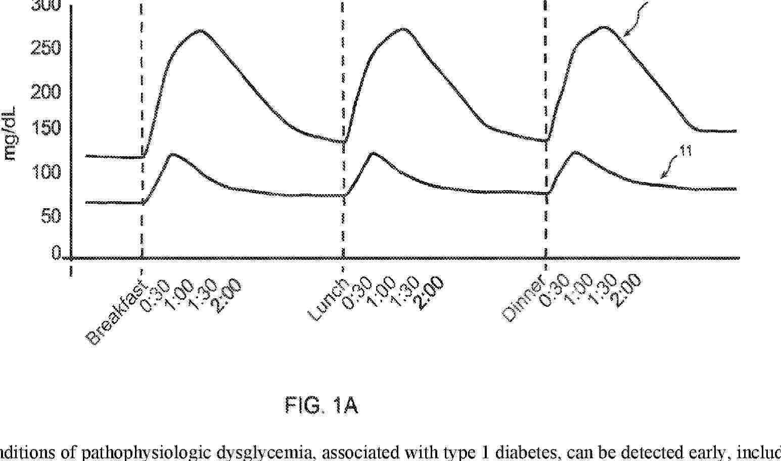
Resumen de: AU2024345572A1
Conditions of pathophysiologic dysglycemia, associated with type 1 diabetes, can be detected early, including in children. Glycemia data is collected by continuous glucose monitoring devices connected to a cloud server. The server learns person-specific patterns of glycemia and trains a model accordingly, which may serve as a baseline for comparison or as the basis for prediction of future patterns. Such models are conditioned by risk factors and various concurrent activities such as exercise and consumption of sugars. Person-specific models trained at different time periods give different simulated patterns of glycemia. Deviations between the simulated patterns, or between the predicted and actual patterns, can indicate progression of pathophysiologic dysglycemia and type 1 diabetes. These models and comparisons can be further interpreted by the software to result in a reported recommendation for additional diagnostic testing or a reported conclusion of diagnosis and recommendation of preventative intervention.

Resumen de: EP4738376A2
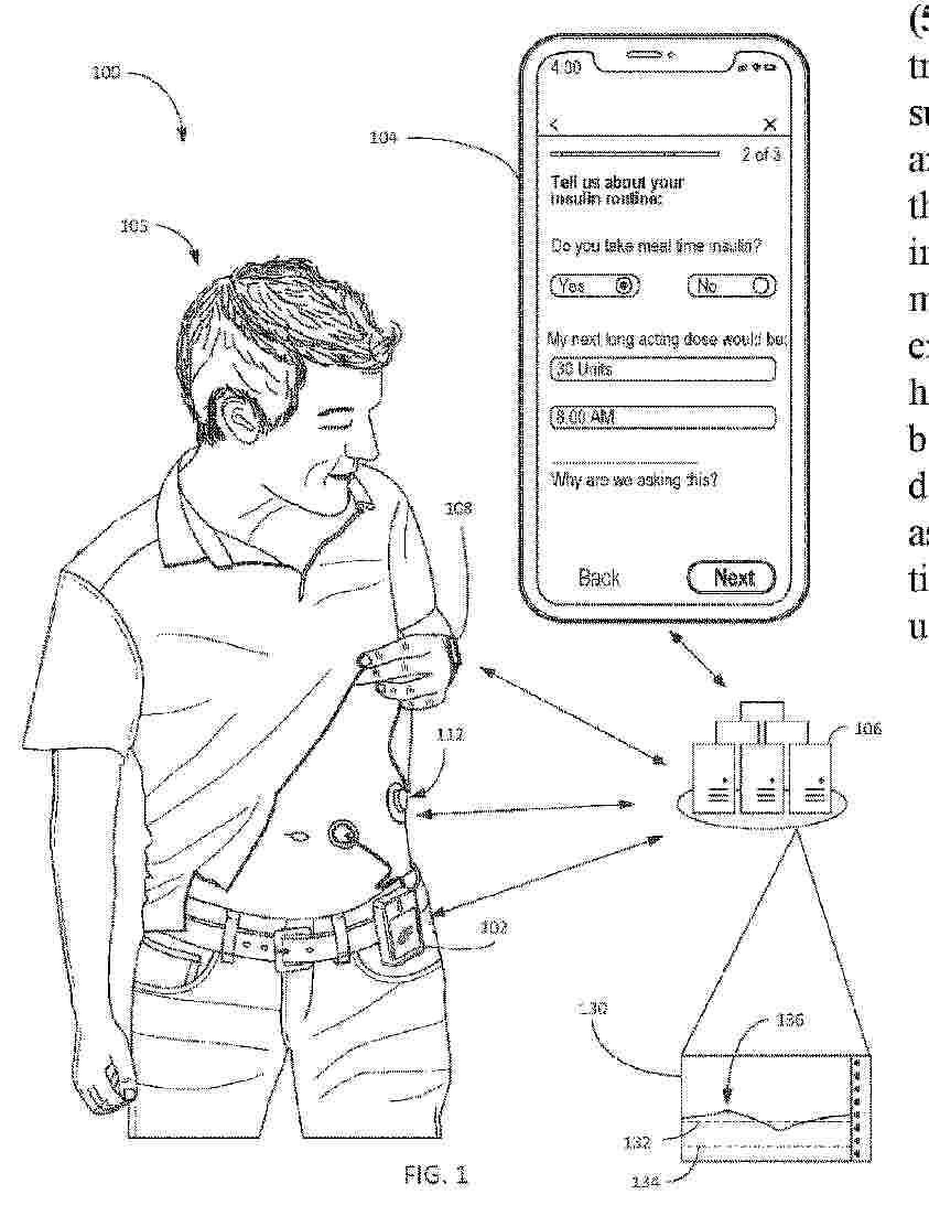
The embodiments described herein may relate to methods and systems for adjusting insulin delivery. Some methods and systems may be configured to adjust insulin delivery to personalize automated insulin delivery for a person with diabetes. Such personalization may include adjusting user specific dosage parameters in response to a user provided insulin delivery amount, including a user provided insulin delivery amount that varies from a recommended insulin delivery amount.
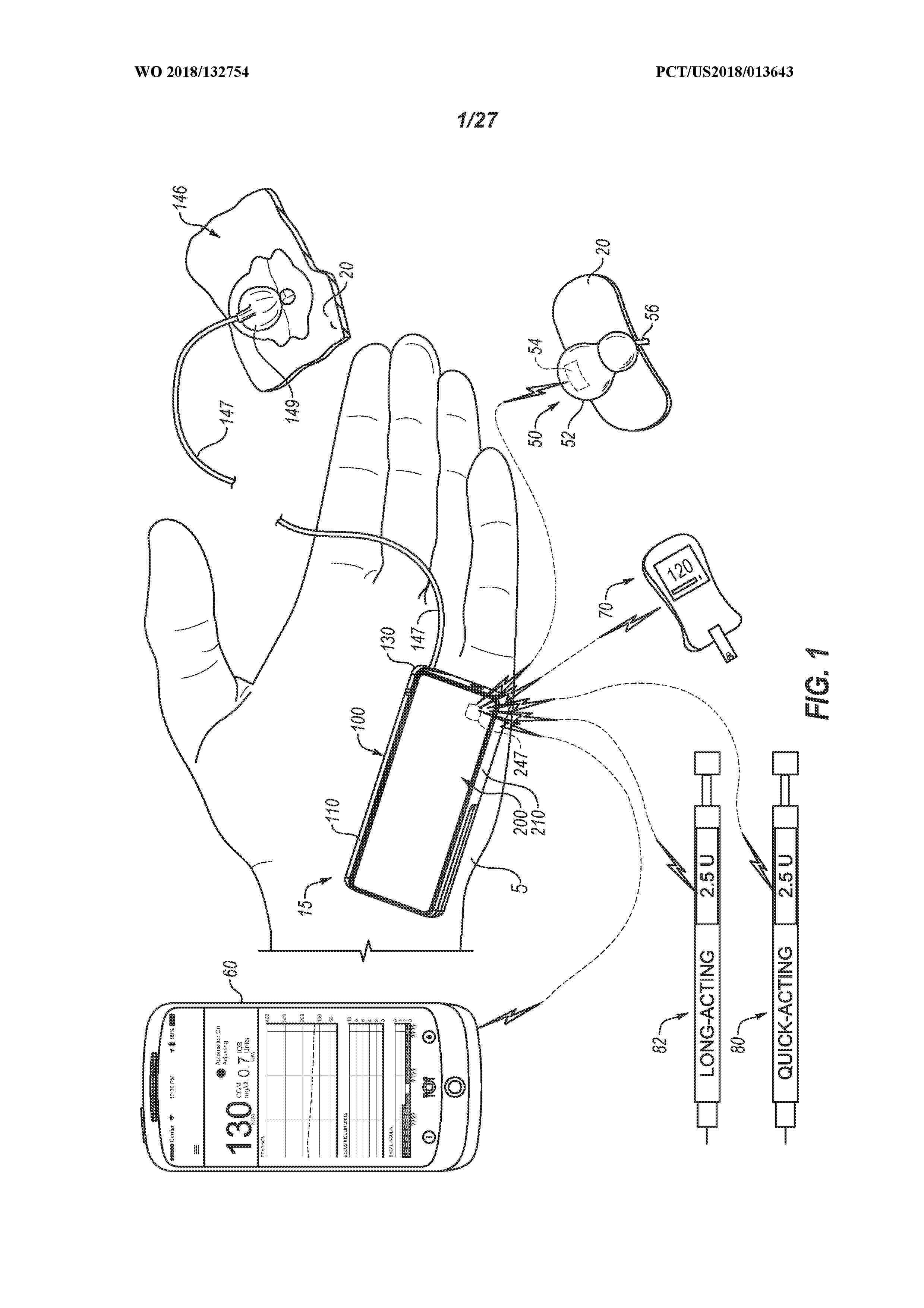
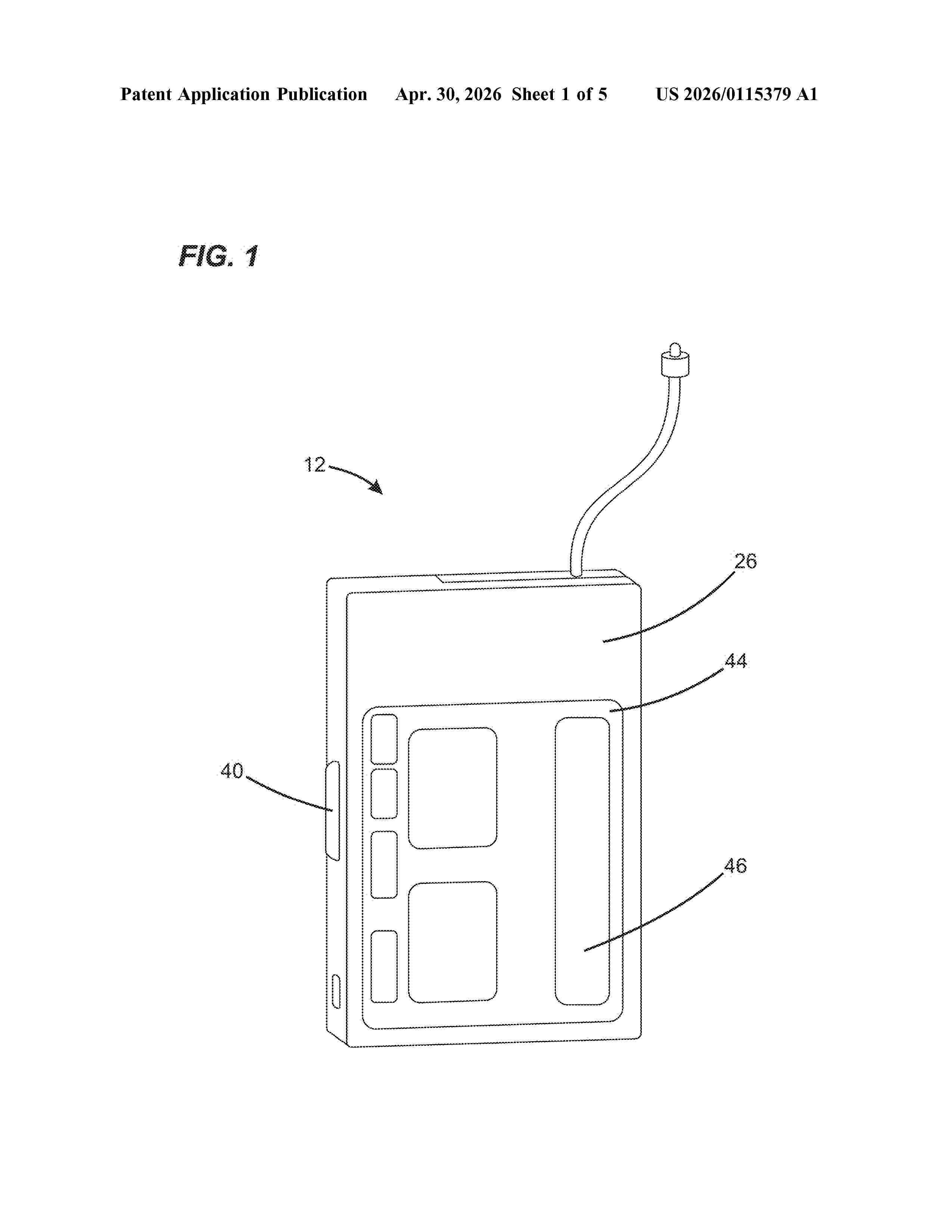
Resumen de: US20260115379A1
0000 Disclosed herein are portable infusion pump systems that provide an ability to simultaneously track insulin on board from insulin deliveries from different sources and/or of different types. A user interface can be provided to enable the user to enter insulin delivered from a source other than the portable infusion pump. A simplified calculation for estimating IOB remaining from each insulin delivery enables such calculations to be carried out with the limited memory and processing capacity of the portable infusion pump.
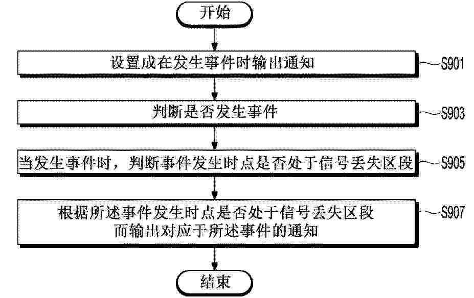
Resumen de: AU2026202716A1
A method of providing an event notification in a glucose monitoring system, comprises: determining whether an event occurs; in response to the occurrence of the event, determining whether the event occurs during a signal loss; determining whether to output a notification corresponding to the event based on a preset priority between the event and the signal loss in the case where the event occurs during the signal loss; and outputting the notification corresponding to the event according to the determination of whether to output the notification. the notification. pr p r
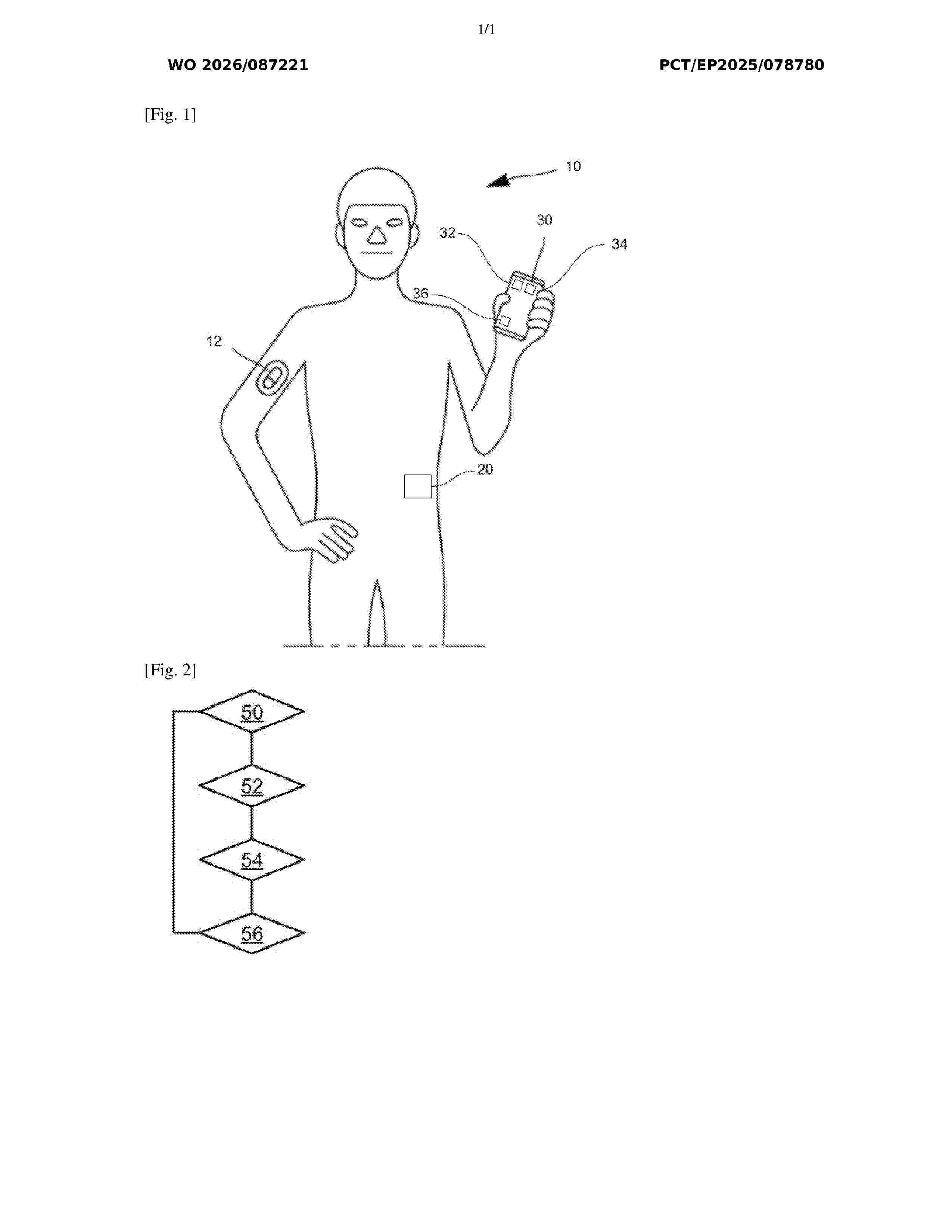
Resumen de: WO2026087221A1
A control device for managing insulin delivery in a closed-loop system. The control device comprises a computation module. The computation module is configured to receive a target basal rate indicative of a rate of a target insulin delivery rate of an insulin pump and compute a supplemental basal rate if the target basal rate is greater than a rate threshold. The supplemental basal rate is sensibly equal to a difference between the target basal rate and the rate threshold. The control device also comprises an insulin management module. The insulin management module is configured to determine a recommendation value of a control parameter of the insulin pump. The recommendation value is based on the supplemental basal rate multiplied by a time period. The control device comprises a communication module. The communication module is configured to send the recommendation value to the insulin pump.
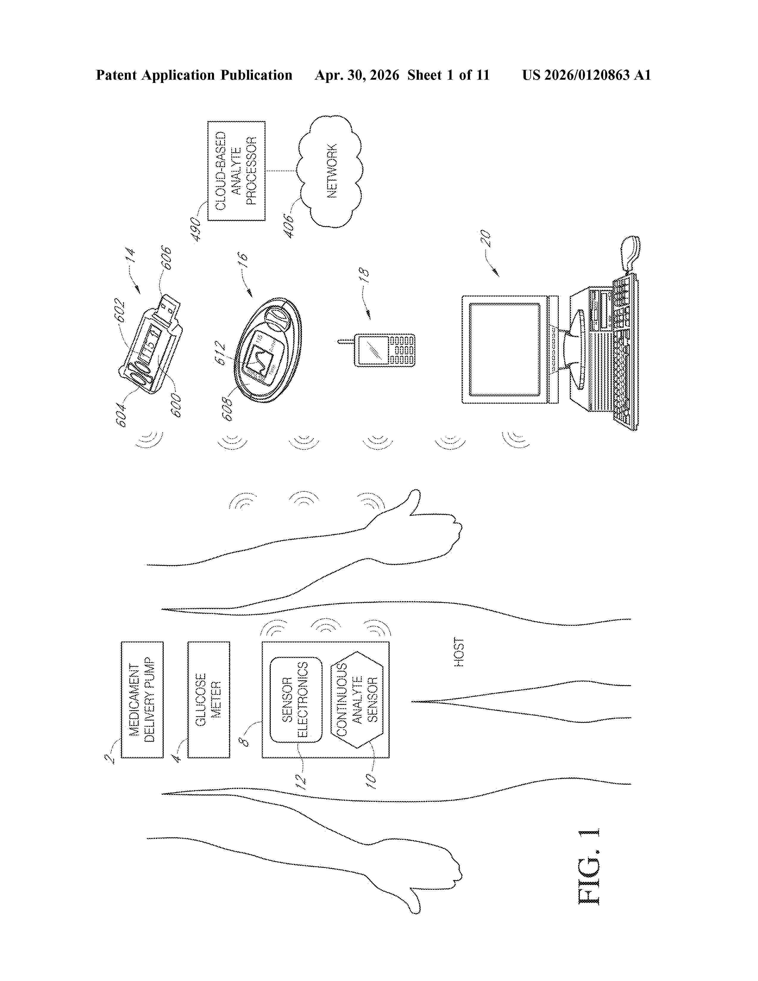
Resumen de: US20260120863A1
Methods and apparatus, including computer program products, are provided for processing analyte data. In some example implementations, a method may include generating glucose sensor data indicative of a host's glucose concentration using a glucose sensor; calculating a glycemic variability index (GVI) value based on the glucose sensor data; and providing output to a user responsive to the calculated glycemic variability index value. The GVI may be a ratio of a length of a line representative of the sensor data and an ideal length of the line. Related systems, methods, and articles of manufacture are also disclosed.
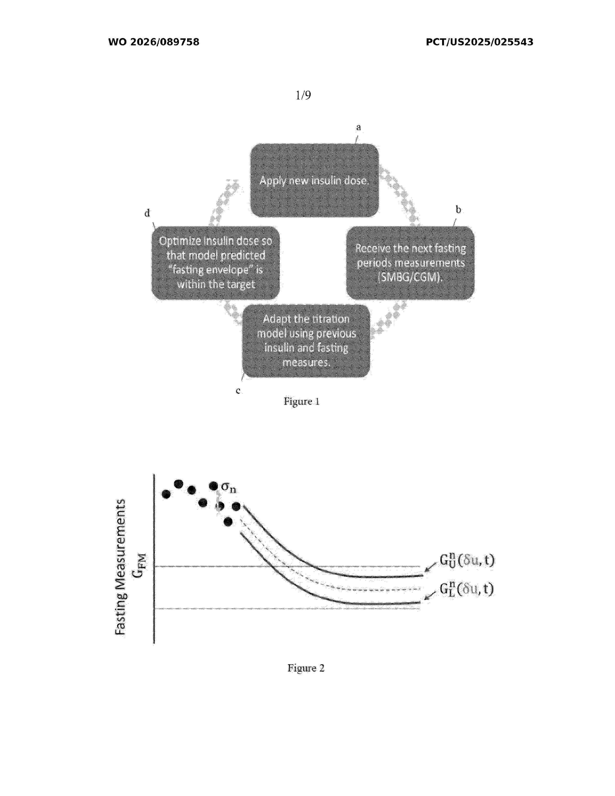
Resumen de: WO2026089758A1
Provided are a method, system, and computer-readable medium for recommending titration measurement for basal insulin dosing and then automatedly causing delivery of the dosing. The recommendation can be personalized to accomplish a weekly recommended dosing according to evaluation for a daily titration glucose level (TGL) determined for received CGM data over the course of a preceding weekly time period. With increased receipt of CGM data, the TGLs can be categorized according to refinement for risk of occurrence of hypoglycemia, and the recommendation may be provided commensurately. In any instance, the recommendation can be automatedly adjusted either upon the CGM data satisfying conditions for hypoglycemia or upon a patient self-reporting hypoglycemia.
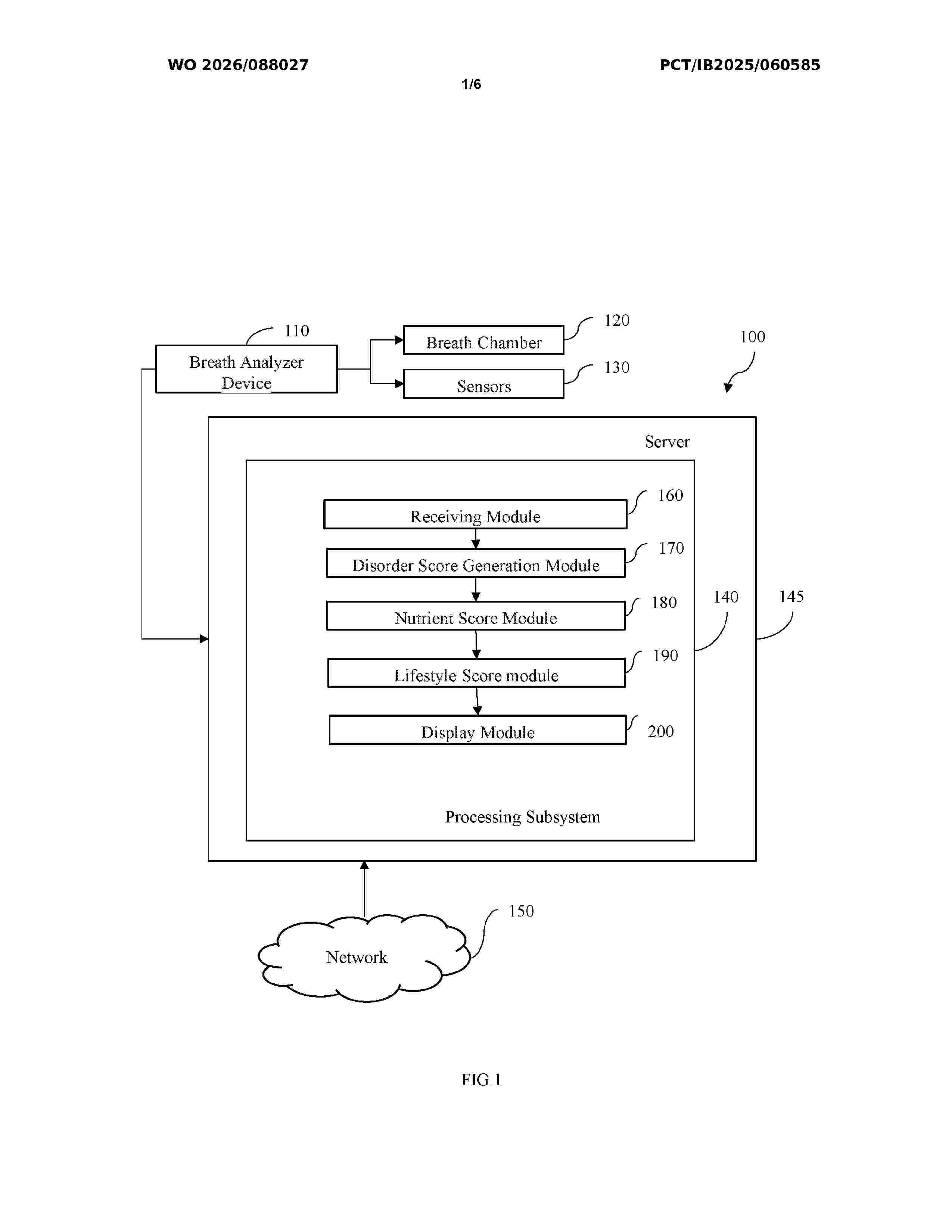
Resumen de: WO2026088027A1
A system (100) for health diagnosis using breath of user and lifestyle assessment is disclosed The system includes a breath analyzer device (110) that includes a breath chamber (120) to receive exhaled breath and detect concentration level of acetone, hydrogen, ethanol, hydrogen, ammonia, carbon monoxide, hydrogen sulphide, 5 lung capacity, hydrogen, methane, ammonia and hydrogen sulphide. The plurality of sensors (130) captures a photoplethysmography signal. A receiving module (160) receives data and the photoplethysmography signal. A disorder score generation module (170) analyses the data to generate a diabetic score, liver disorder score, respiratory disorder score, digestive. A nutrient score module (180) calculates a 10 nutrient score. A lifestyle score module (190) calculates a lifestyle score. A display module (200) displays diabetic score, liver disorder score, respiratory disorder score, digestive disorder score, kidney disorder score, nutrition score, lifestyle score, and the plurality of health parameters via a user interface.
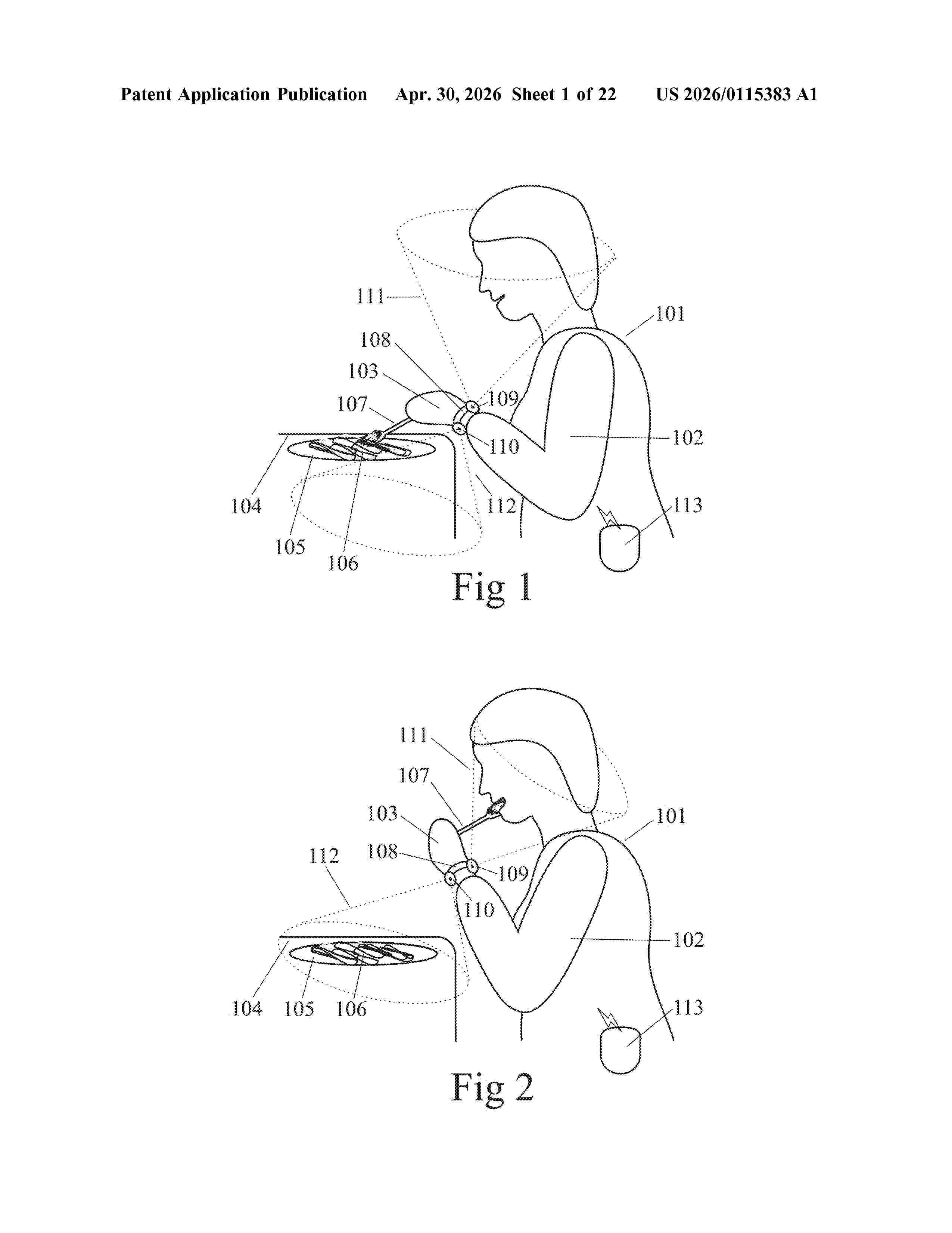
Resumen de: US20260115383A1
0000 A wearable device or system for monitoring food consumption can include a head-worn device such as eyewear which is worn by a person and a plurality of brain activity sensors on the head-worn device, wherein data from the plurality of brain activity sensors is analyzed to detect when the person is eating. This device can be used alone or as part of a closed-loop glucose level management system.
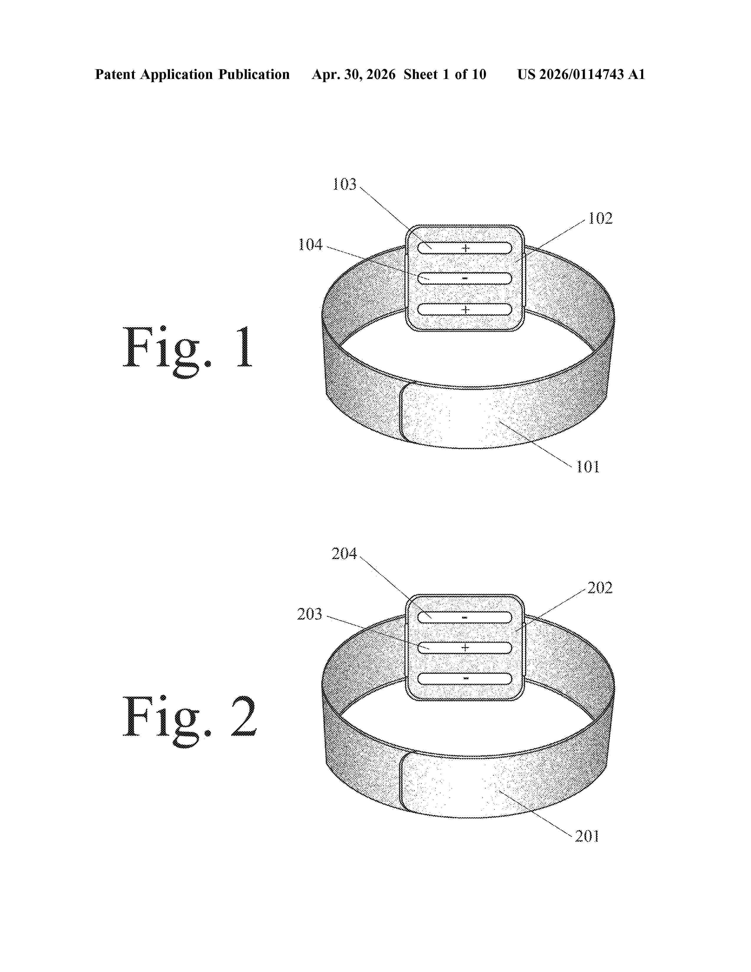
Resumen de: US20260114743A1
A biometric wearable device is embodied in a finger ring or smart watch with radiowave or microwave energy emitters/transmitters and energy receivers to measure the level of a biometric parameter such as body oxygenation, hydration, or glucose level. The energy emitter/transmitter and the energy receiver can be parallel, nested, and/or comprise a two-dimensional array. The device can further comprise a split ring resonator located between the energy emitter/transmitter and the energy receiver.
Resumen de: US20260120843A1
0000 A wearable device or system for monitoring food consumption can include a wrist-worn or finger-worn device which is worn by a person, a motion sensor on the wrist-worn or finger-worn device, eyewear which is worn by the person, and a camera on the eyewear which is activated to record food images when analysis of data from the motion sensor detects that the person is eating. This device can be used alone or as part of a closed-loop glucose level management system.
Resumen de: US20260114742A1
A biometric wearable device is embodied in a smart watch or finger ring with radiowave or microwave energy emitters/transmitters and energy receivers to measure the level of a biometric parameter such as body oxygenation, hydration, or glucose level. The energy emitter/transmitter and the energy receiver can be parallel, nested, and/or comprise a two-dimensional array. The device can further comprise a split ring resonator located between the energy emitter/transmitter and the energy receiver.
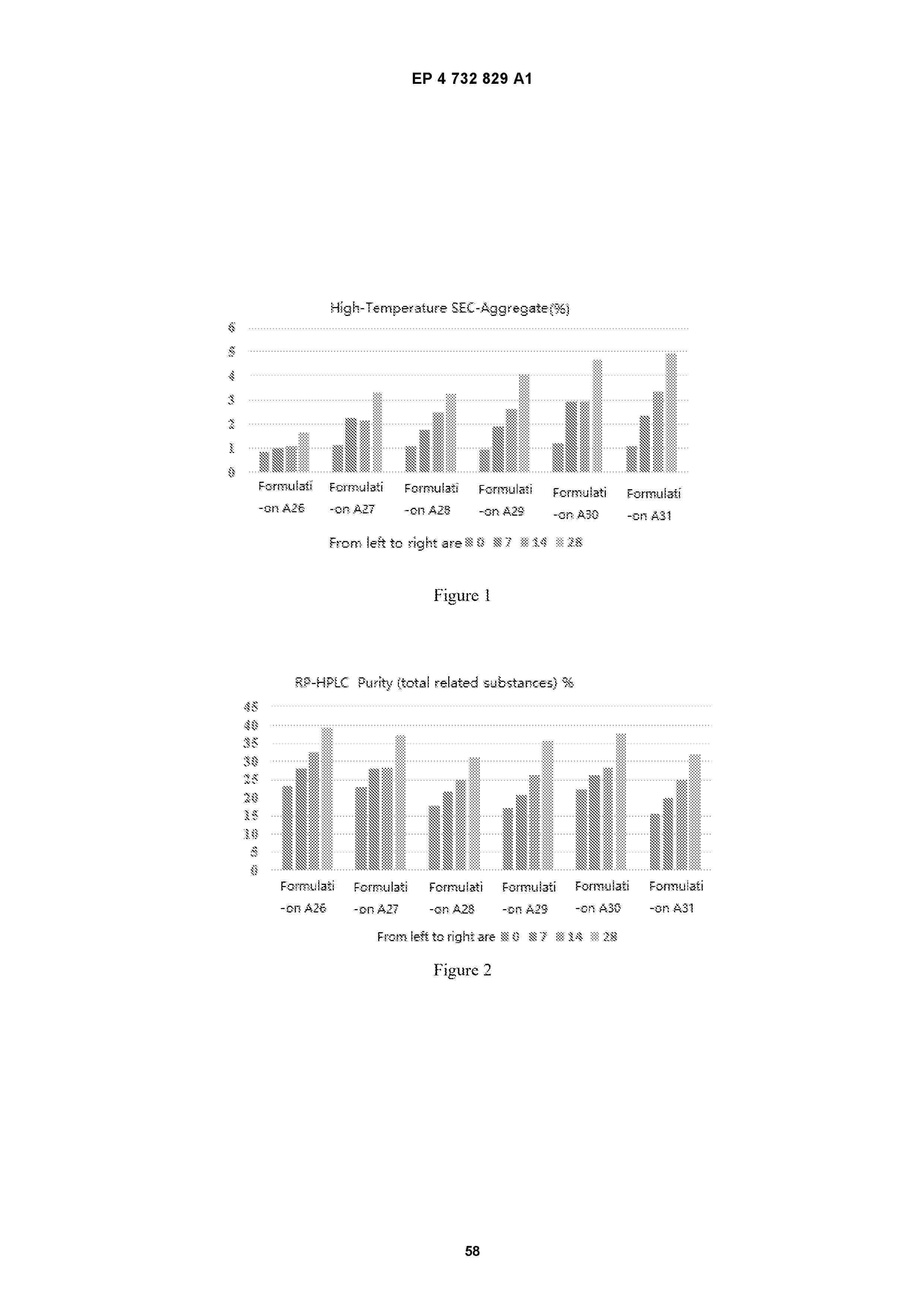
Resumen de: EP4732829A1
0001 A GLP-1-Fc-FGF21 double-target fusion protein composition and the use thereof. The composition comprises a GLP-1-Fc-FGF21 fusion protein and a buffer solution. In the composition, by means of adding the buffer solution, the generation of visible particles can be effectively controlled, and the stability of the GLP-1-Fc-FGF21 fusion protein is improved, so that the shelf life of a product can be prolonged. The composition can be used for treating and/or preventing metabolic diseases, such as diabetes, hyperlipidemia, obesity and diseases related to fatty liver.
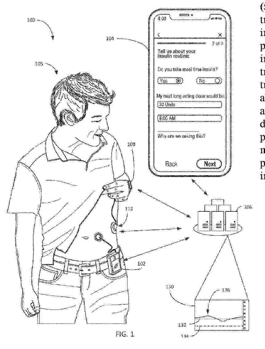
Resumen de: WO2024263758A1
Systems and methods are provided for determining patterns, trends, anomalies, and/or abnormalities in data relating to operation of an insulin delivery pump and user outcomes relating to an insulin delivery pump and determining certain actions and/or operational adjustments to improve the user outcomes, such as blood glucose levels. For example, troubleshooting actions may be recommended upon determining a pattern, trend, abnormality, and/or anomaly in blood glucose levels that is undesirable. In another example, operation of the insulin delivery pump may be adjusted based habits and/or behaviors of the user. For example, insulin delivery timing may be adjusted based on exercise, activity and/or eating patterns. Based on the detected patterns, trends, anomalies, and/or abnormalities, a user device such as a mobile phone or smart device may present prompts for more information, alerts, status updates, and other information intended to improve the user experience.
Resumen de: WO2024263756A1
Systems and methods are provided for determining patterns, trends, anomalies, and/or abnormalities in data relating to operation of an insulin delivery pump and user outcomes relating to an insulin delivery pump and determining certain actions and/or operational adjustments to improve the user outcomes, such as blood glucose levels. For example, troubleshooting actions may be recommended upon determining a pattern, trend, abnormality, and/or anomaly in blood glucose levels that is undesirable. In another example, operation of the insulin delivery pump may be adjusted based habits and/or behaviors of the user. For example, insulin delivery timing may be adjusted based on exercise, activity and/or eating patterns. Based on the detected patterns, trends, anomalies, and/or abnormalities, a user device such as a mobile phone or smart device may present prompts for more information, alerts, status updates, and other information intended to improve the user experience.
Resumen de: US20260108215A1
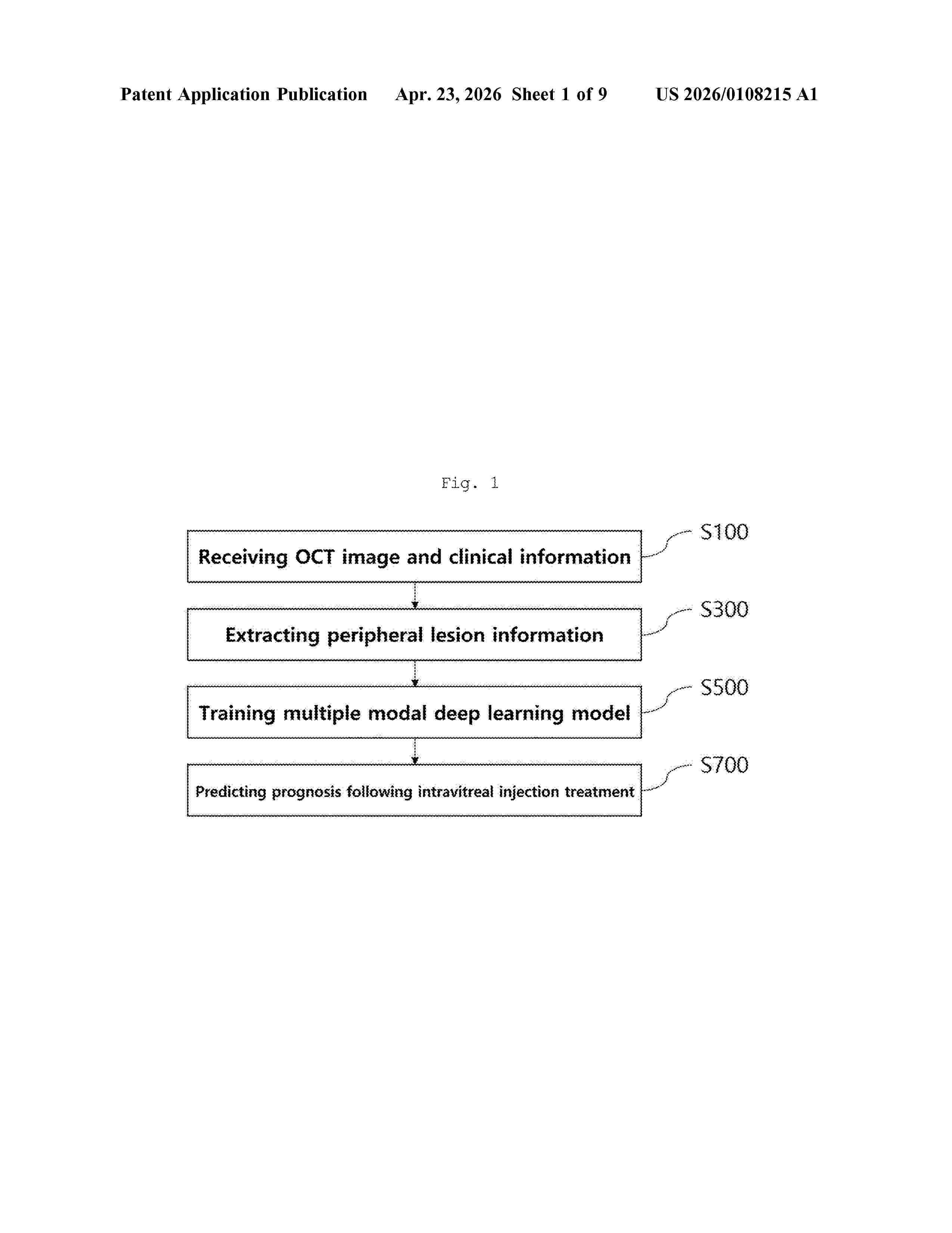
0000 The present invention relates to a method for predicting the prognosis of intravitreal injection treatment, comprising the steps of: receiving OCT images and clinical information of a plurality of diabetic macular edema patients; extracting one or more major lesion information from the OCT images; training a multi-modal deep learning model by inputting the OCT images, the clinical information, and the one or more major lesion features, and outputting the intravitreal injection treatment prognosis of the diabetic macular edema patients; and predicting the prognosis of intravitreal injection treatment by inputting the OCT images, the clinical information, and the major lesion features of a specific diabetic macular edema patient to the trained multi-modal deep learning model.
Resumen de: WO2026083250A1
The objective invention provides a parenteral composition of semaglutide or a pharmaceutically acceptable salt thereof for subcutaneous administration, having a strength and composition such that it can be administered multiple times from single article of manufacture, for use in treating type 2 diabetes mellitus and for weight loss, thereby providing benefit to the patient.
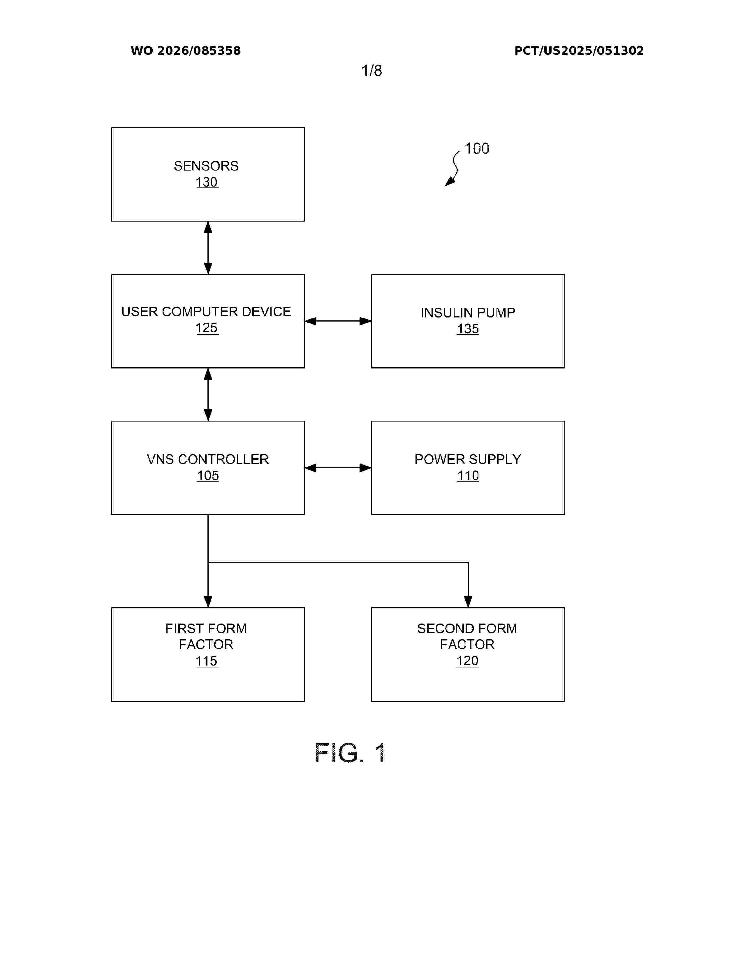
Resumen de: WO2026085358A1
A method of improving glycemic control is provided. The method includes stimulating a cutaneous distribution of a subject's vagus nerve within the subject's ear with a nerve stimulating signal. The method also includes monitoring the subject's blood glucose. The method further includes administering insulin infusions to the subject.
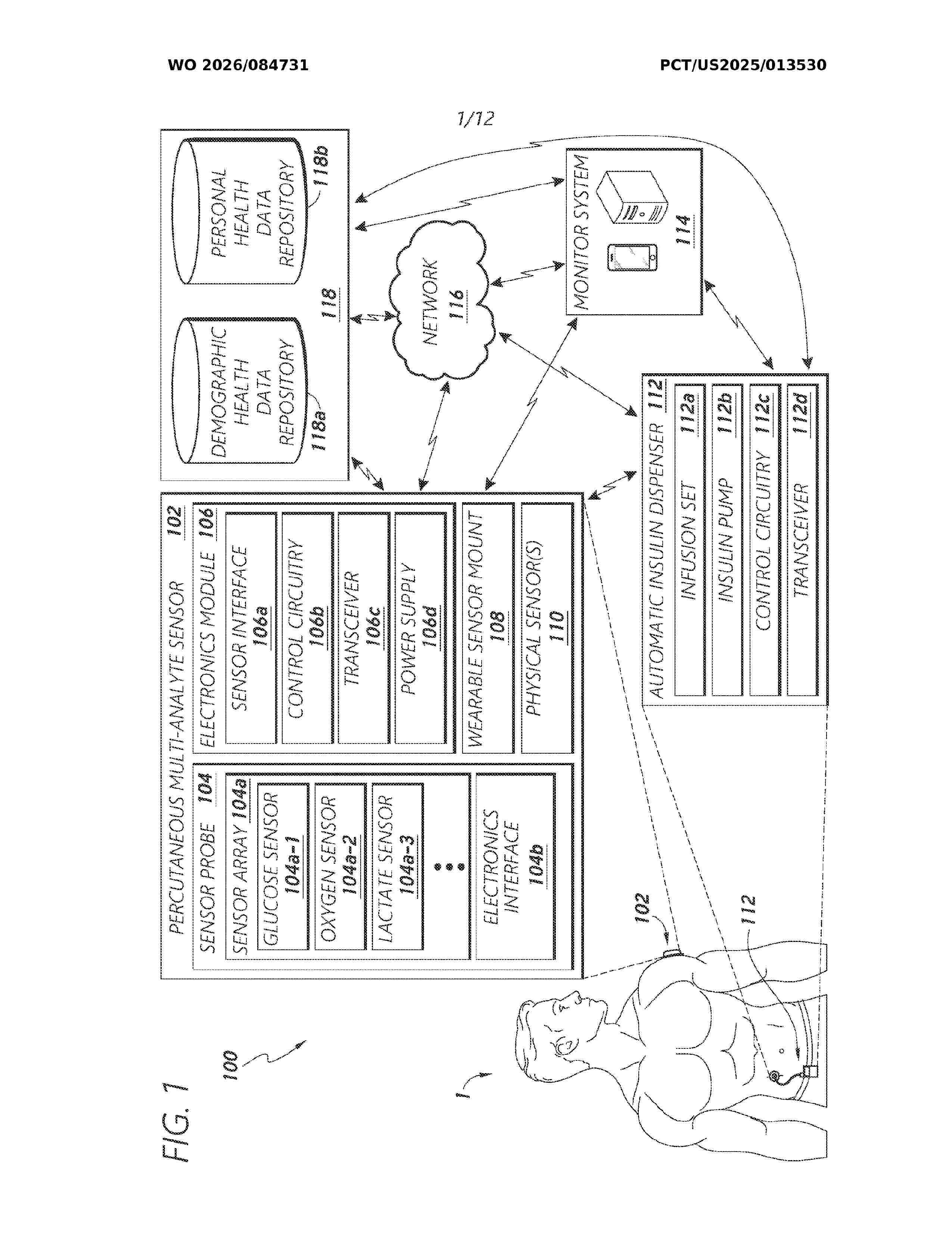
Resumen de: WO2026084731A1
A multi-analyte sensor system is disclosed. The system includes a sensor probe that has a first set of electrodes that transduce glucose into electrical signals, a second set of electrodes that transduce lactate into electrical signals and a third set of electrodes that provide working and counter electrode functionality for the first and second set of electrodes. The system has an electronics module that electrically interfaces with the sensor probe, and includes a transceiver configured to transmit sensor data. The system also includes control circuitry communicatively coupled to the electronics module that determines a glucose state based on signals from the first set of electrodes and also determine a lactate state based on signals from the second set of electrodes. The control circuitry also generates an insulin infusion pump control signal based on signals from the first and second set of electrodes.
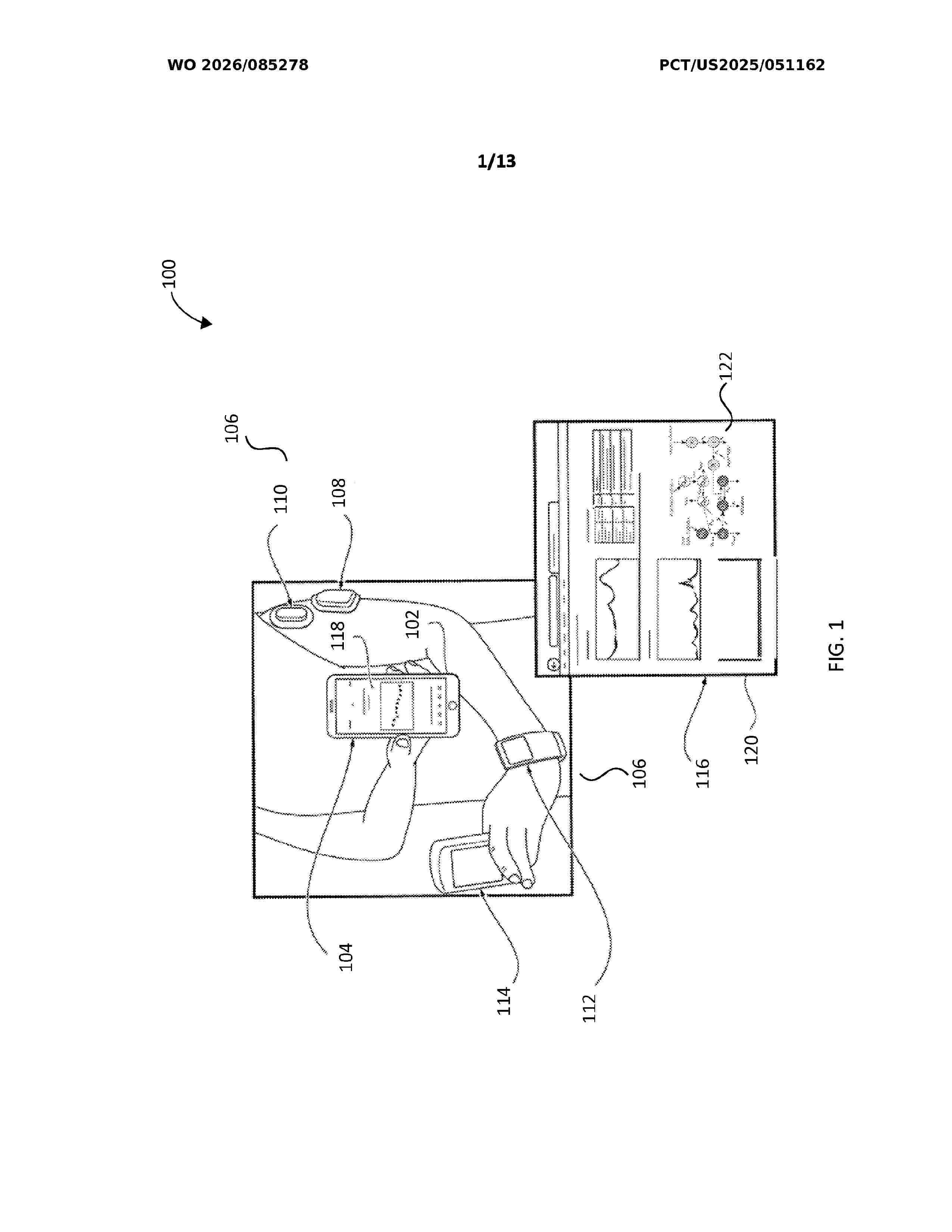
Resumen de: WO2026085278A1
Systems and methods are disclosed for managing a person's blood glucose concentration within a predetermined range by co-administration of insulin and pramlintide using an automated insulin delivery system. A model predictive control (MPC) algorithm that includes a glucoregulatory control model augmented with a compartment model of pramlintide pharmacokinetics and pharmacodynamics is utilized. In some embodiments, the person may announce in advance meals to be consumed and the pramlintide-aware MPC algorithm uses this data as input to the glucoregulatory control model. In other embodiments, an automatic meal detection and size estimation algorithm is incorporated into the system to relieve the person of the burden of meal entry and carbohydrate estimation.
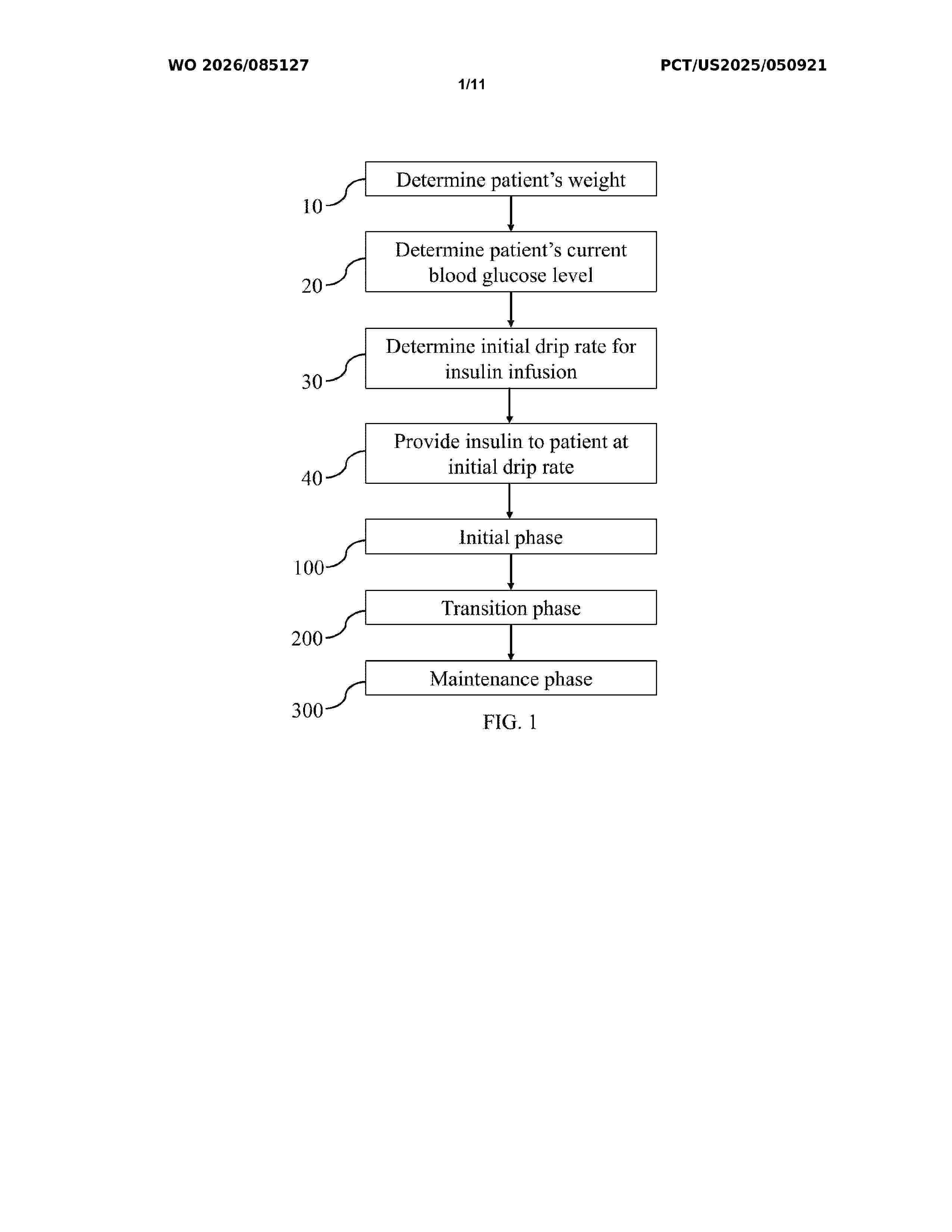
Resumen de: WO2026085127A1
A method of administering insulin to a patient to achieve and maintain euglycemia is disclosed. The method includes administering insulin to the patient at a drip rate that is based on a current blood glucose level of the patient and a weight of the patient. Insulin is administered during an initial phase, a transition phase (during which blood glucose level decreases slower than during the initial phase), and a maintenance phase. During the maintenance phase, the method includes adjusting the drip rate periodically based on a current drip rate and a percentage change in blood glucose level during a period of time. In addition, the maintenance phase considers a lookback period in which the drip rate is adjusted based on trends during the lookback period.
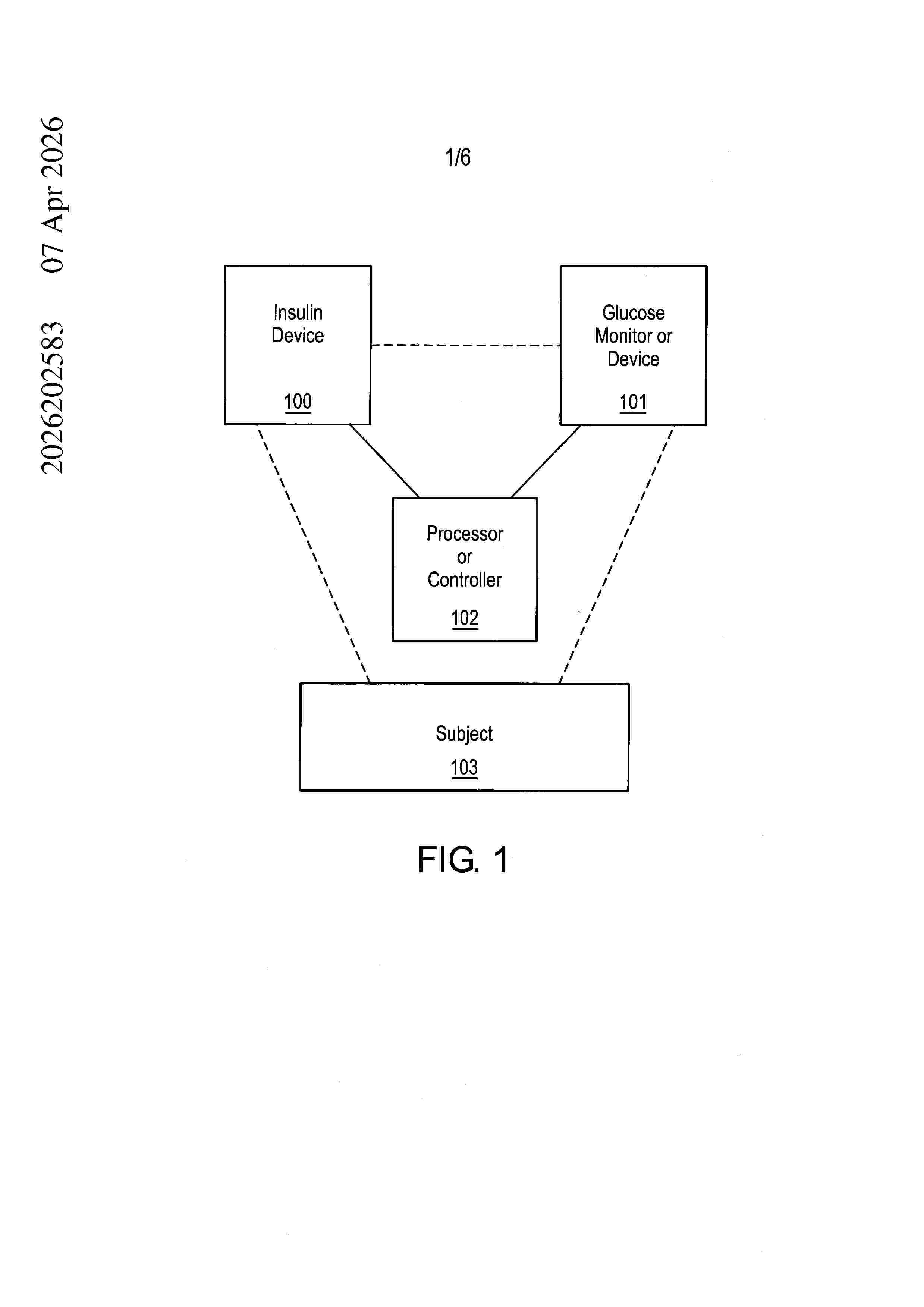
Resumen de: AU2026202583A1
22573194_1 (GHMatters) P45417AU02 An insulin device configured to control an insulin dosage by adapting a basal rate profile. The insulin device includes a sensor configured to produce a blood glucose level measurement data, and detect changes of the blood glucose level measurement data over time; a processor and associated computer memory device configured to receive the blood glucose level measurement data and a basal rate profile, such that the basal rate profile includes a basal rate set point that corresponds to an insulin delivery reference for a nominal blood glucose, and the basal rate profile is stored in the computer memory device. The insulin device also includes an an insulin dispensing valve controlled by the processor to administer insulin in accordance with the received basal rate profile, such that the processor is configured to update the basal rate set point over a time period based on both an assessment of at least one of a risk of hyperglycemia and a risk of hypoglycemia from historical blood glucose data, and patterns of actions taken by the insulin device to mitigate glycemic risk during the time period. The insulin dispensing valve is controlled by the processor to administer insulin in accordance with the updated basal rate set point. pr p r
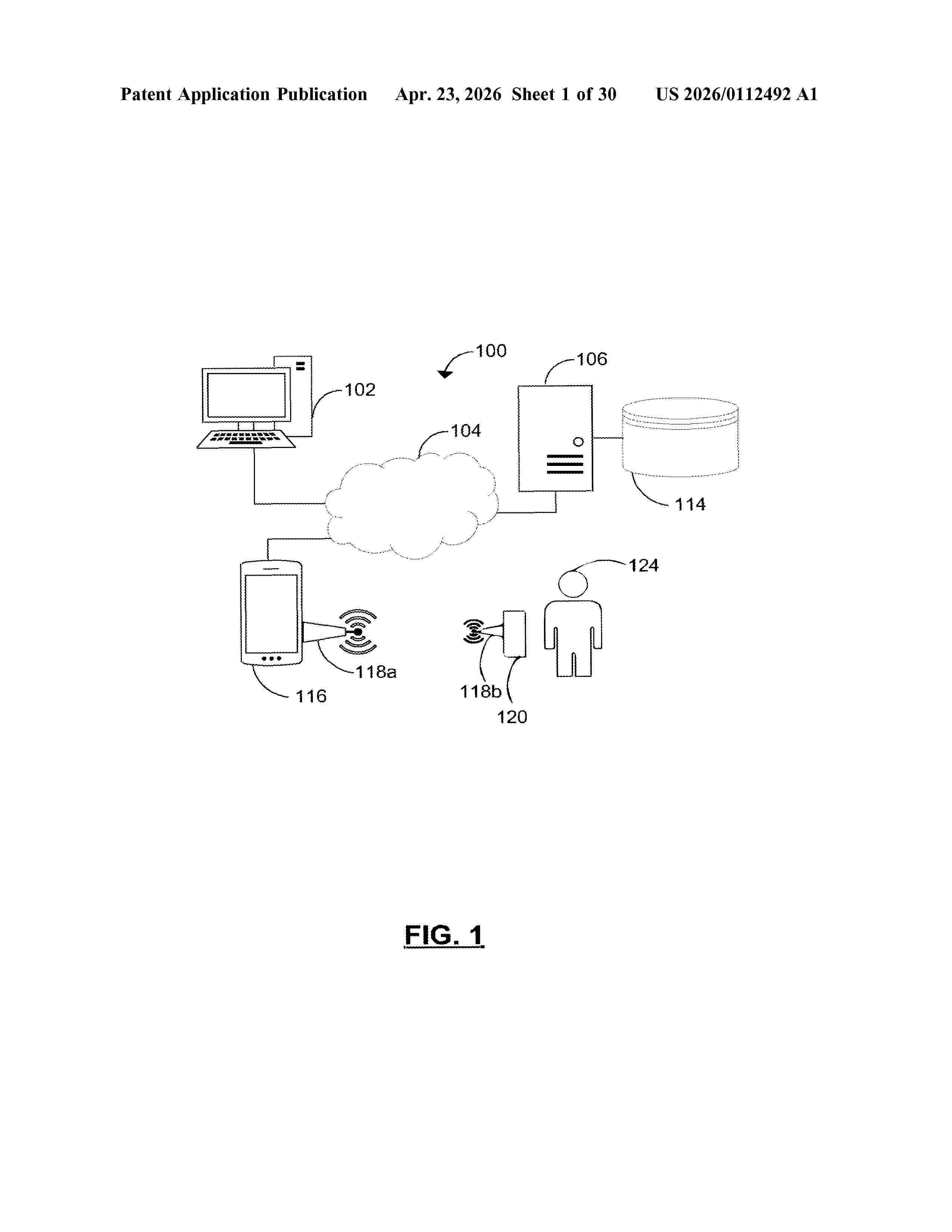
Resumen de: US20260112492A1
Provided are methods and systems for generating a model for determining blood glucose levels using voice samples. This includes receiving, at a processor: a plurality of voice samples from at least one subject at a plurality of time points; and a plurality of blood glucose levels, wherein each blood glucose level in the plurality of blood glucose levels is temporally associated with a voice sample in the plurality of voice samples; sorting, at the processor, the plurality of voice samples into two or more blood glucose level categories based on the blood glucose levels; extracting, at the processor, voice feature values for a set of voice features from each of the plurality of voice samples; selecting, at the processor, a subset of voice features from the set of voice features; and generating at the processor, the blood glucose level prediction model based on the subset of voice features.
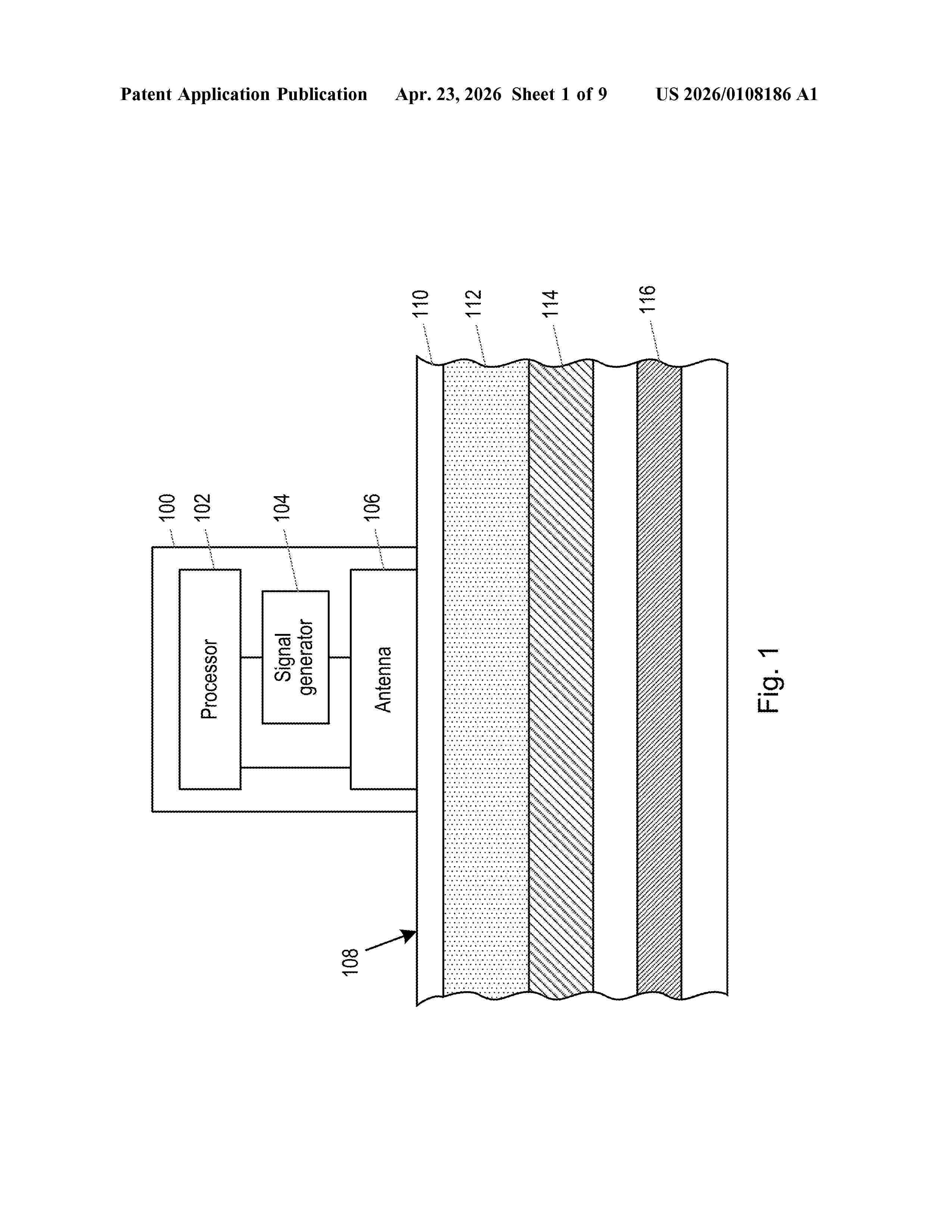
Resumen de: US20260108186A1
0000 According to an aspect, there is provided a computer-implemented method (200) of determining a concentration of glucose in a subject's blood, the method comprising acquiring (202) first measurement data indicative of a response resulting from an electromagnetic (EM) signal interacting with the subject's blood in a body part of the subject, the EM signal having been emitted from a device in contact with the body part of the subject; acquiring (204) second measurement data indicative of a pressure applied to the body part of the subject by the device; and using (206) a predictive model to infer a concentration of glucose in the subject's blood from the first measurement data and the second measurement data, the predictive model having been trained to infer a concentration of glucose in the subject's blood from the first measurement data and the second measurement data.
Nº publicación: US20260108742A1 23/04/2026
Solicitante:
PIERCE RYAN KENDALL [US]
CLINE BENJAMIN KAHN [US]
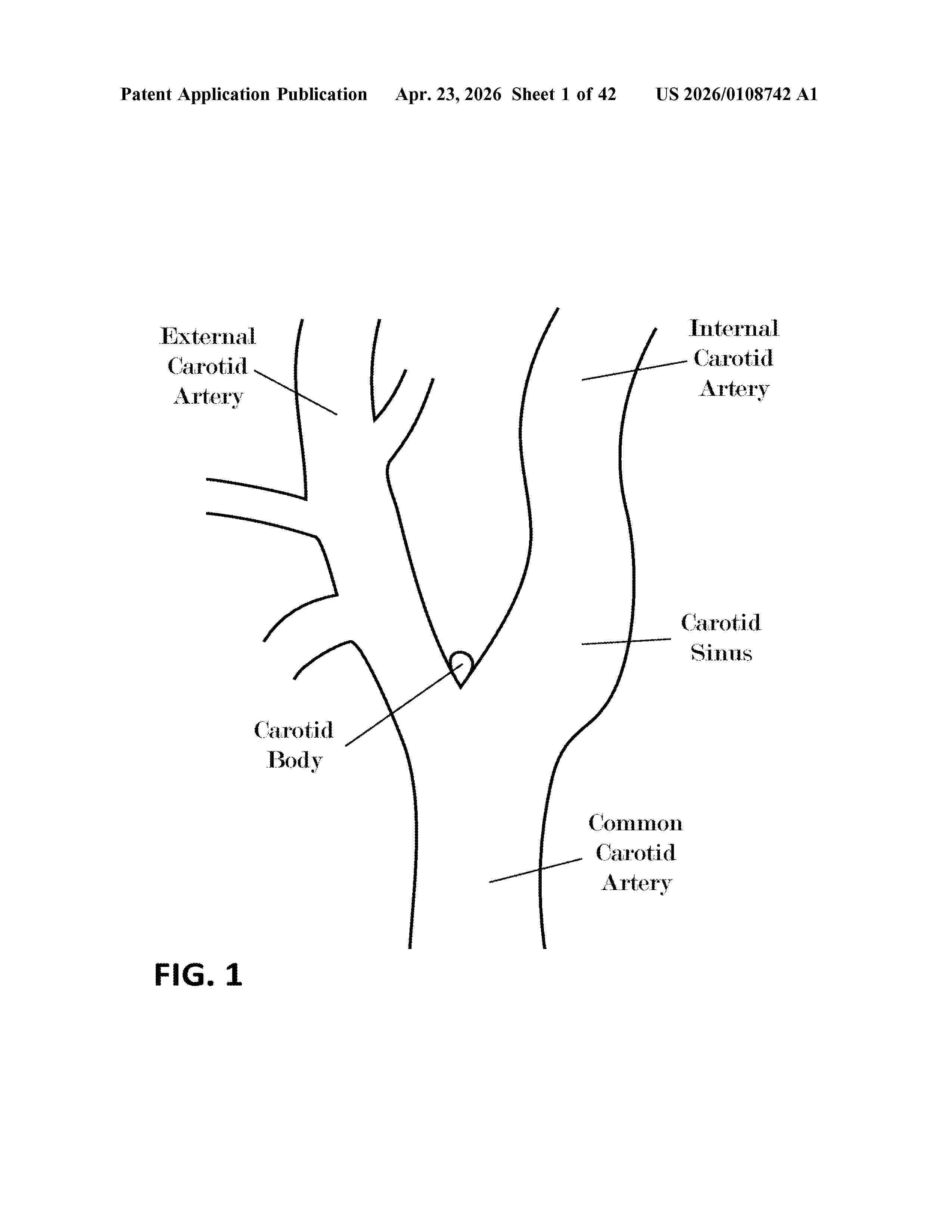
Resumen de: US20260108742A1
Devices and methods described herein may, among other uses, favorably cause the activation and/or deactivation of vascular baroreceptors in order to achieve a desired impact on a physiological condition, such as baroreflex-regulated conditions, hypertension, hypotension, nervous system disorders, metabolic disorders, cardiovascular disease, heart failure, cardiac arrhythmia, renal disease, respiratory disease, diabetes, and insulin resistance. The devices and methods may be used in concert with each other and/or other treatments, medications, interventions, or behavioral regimens. They may also be used in concert with devices and methods that perform or assist with assessing or measuring a mammal's blood pressure, assessing, measuring, or predicting the impact of the described methods and devices on the patient's condition (including blood pressure), and/or protecting the surrounding anatomy from adverse effects.
 BOPI
BOPI
 Sede Electrónica