Si deseas distinguir tus productos, servicios o ambos de los de otra empresa, es posible que necesites una marca o nombre comercial. Descubre qué son, en qué consiste su procedimiento de registro y qué implica.

Información sobre los plazos de presentación de solicitudes de transformación de marcas de la Unión Europea en marca nacional española. Más información


Si tienes un nuevo dispositivo, producto o procedimiento que resuelva un problema técnico o tenga una ventaja práctica, existen distintas formas de protegerlo en España y en otros países. Descubre cómo hacerlo.

¿Tu innovación reside en la estética, la ornamentación o la apariencia de tu producto? Protégela mediante un diseño industrial. Descubre qué derechos confiere el registro y cómo realizar la tramitación.

Las patentes publicadas en todo el mundo son una valiosa fuente de información científica, técnica y comercial.
El Bono 3 (patentes nacionales, patentes europeas, informes tecnológicos de patentes y búsquedas retrospectivas) se encuentra cerrado desde el 19 de junio. La solicitud de ayudas para los Bonos 1, 2 y 4 permanecen abiertos.

Si eres emprendedor/a o una empresa y quieres potenciar y mejorar la rentabilidad de tu negocio protegiendo de forma adecuada los activos intangibles de tu organización, en este espacio encontrarás lo necesario.


 156
resultados
156
resultados
 Última actualización
06/08/2025 [06:56:00]
Última actualización
06/08/2025 [06:56:00]


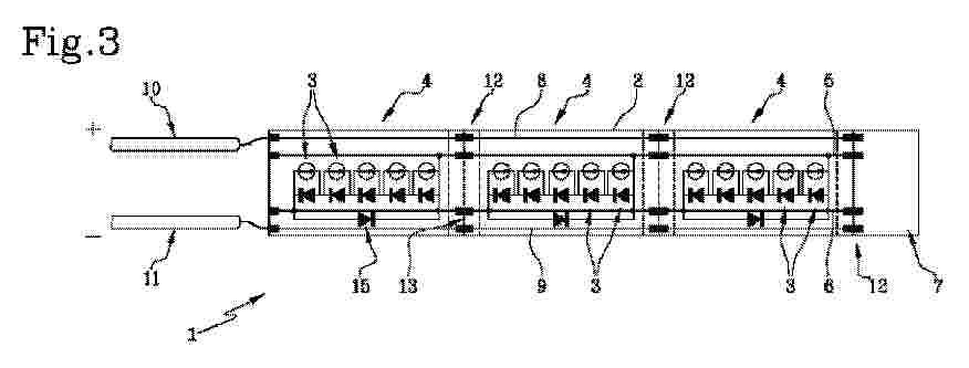
Resumen de: FR3158848A1
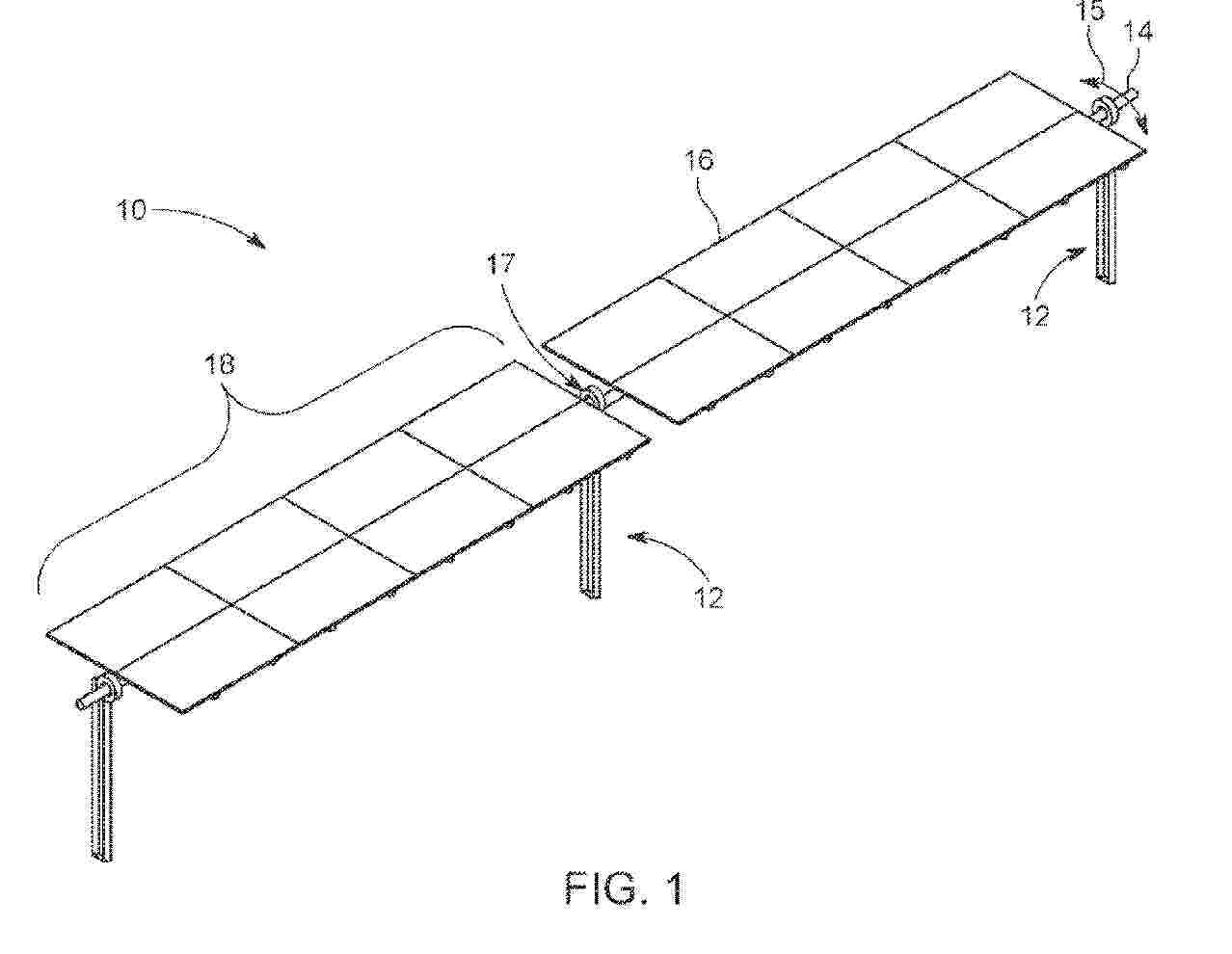
GÉNÉRATEUR ÉLECTRIQUE, PROCÉDÉ DE CONVERSION ET PROCÉDÉ D’UTILISATION D’UN TEL GÉNÉRATEUR ÉLECTRIQUE Un générateur électrique comporte des modules photovoltaïques (1), une station (6) et une station additionnelle (10) reliées par un câble porteur (4a) supportant les modules photovoltaïques (1) et un câble tracteur (4b) déplaçant les modules photovoltaïques (1). Chaque module photovoltaïque (1) est fixé au câble tracteur (4b) par un connecteur (5) débrayable. Une station (6) est munie de moyens de déplacement du câble tracteur (4b) pour déplacer les modules photovoltaïques (1) le long de la boucle par rapport à la station (6). Un circuit de commande (9) est configuré pour déplacer les modules photovoltaïques (1) d’une position de production à une position de repos en déplaçant le câble tracteur (4b).

Resumen de: US2025247039A1
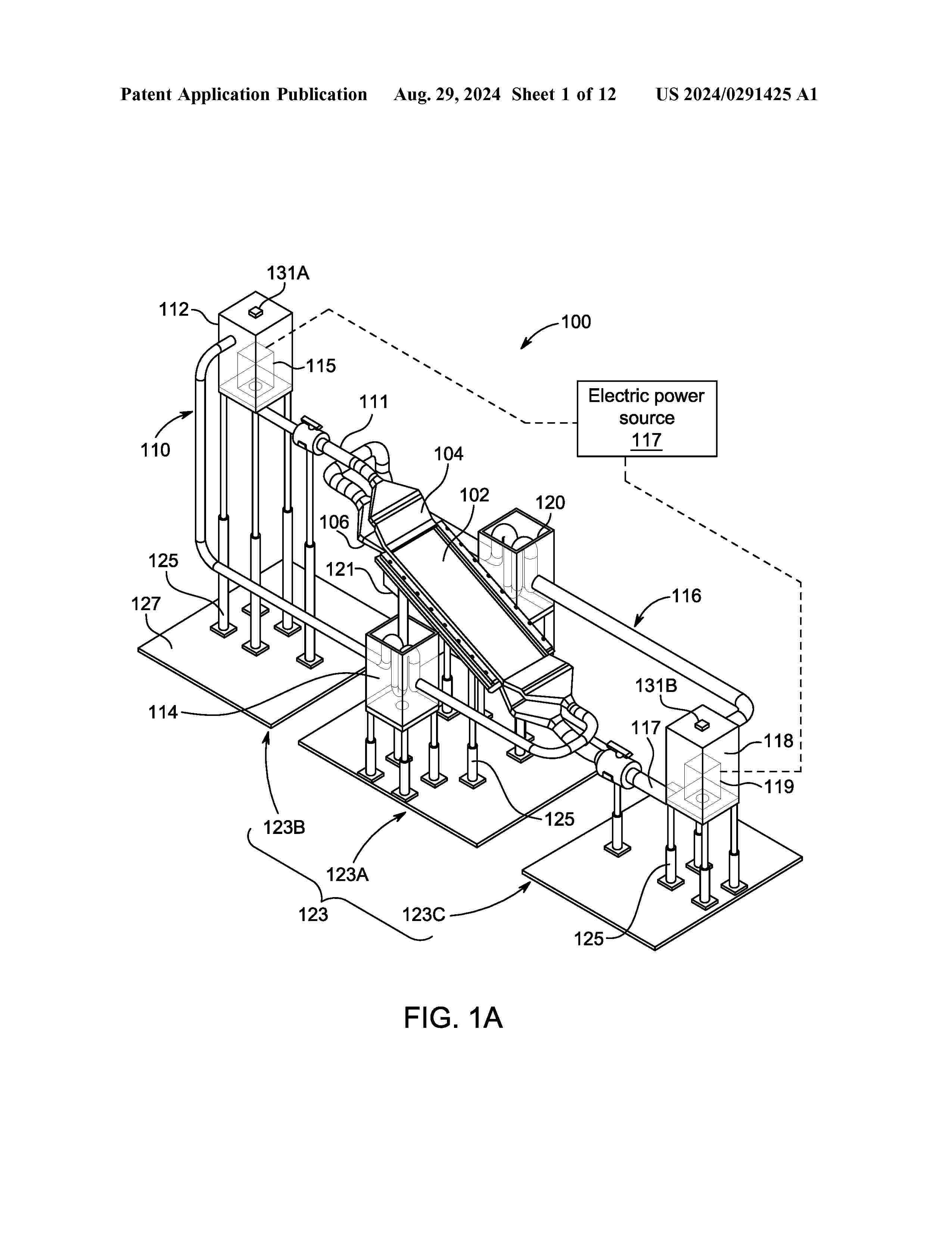
Aspects of the present disclosure are directed to an electrolysis chamber. In some aspects, the electrolysis chamber includes a floor and sidewalls defining an interior region configured to contain an electrolyte solution; a cation pod and an anion pod disposed in the interior region, each of the cation pod and the anion pod including a gas containment cap terminating at a respective gas vent port; a pod divider extending from the gas containment caps partway toward the floor so as to separate at least a portion of the cation pod from the anion pod; a plurality of vertically stacked cation electrolysis mesh screens arranged within the cation pod; and a plurality of vertically stacked anion electrolysis mesh screens arranged within the anion pod.
Resumen de: US2025247041A1
A building integrated thermal and photovoltaic cladding system includes: an exterior layer including photovoltaic elements, an interior layer including heat exchange modules; a load-bearing structure including one or more spacers configured to maintain the exterior layer in spaced apart relation to the interior layer, and providing an air flow conduit therebetween for receiving air from the exterior, the air flow generally passing over the interior layer by natural circulation.
Resumen de: US2025246388A1
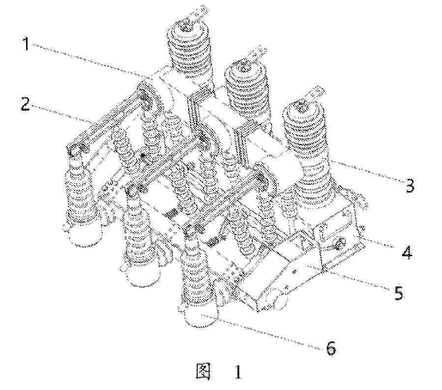
Embodiments of the invention provides a smart outdoor switchgear for control and protection of connection and disconnection of a medium-voltage microgrid, which includes: a current transformer, an isolating switch mechanism, an outdoor circuit breaker, an electric isolating driving mechanism and an outdoor jet type fuse. The current transformer is installed on an outlet end of the outdoor circuit breaker. The isolating switch mechanism is connected to the current transformer, and the isolating switch mechanism is connected to the outlet end of the outdoor circuit breaker through the current transformer. A top of the isolating switch mechanism on a side away from the current transformer is connected to a top of the outdoor jet type fuse, and a bottom of the isolating switch mechanism on the side away from the current transformer is connected to a bottom of the outdoor jet type fuse. The electric isolating driving mechanism is installed on the bottom of the isolating switch mechanism.
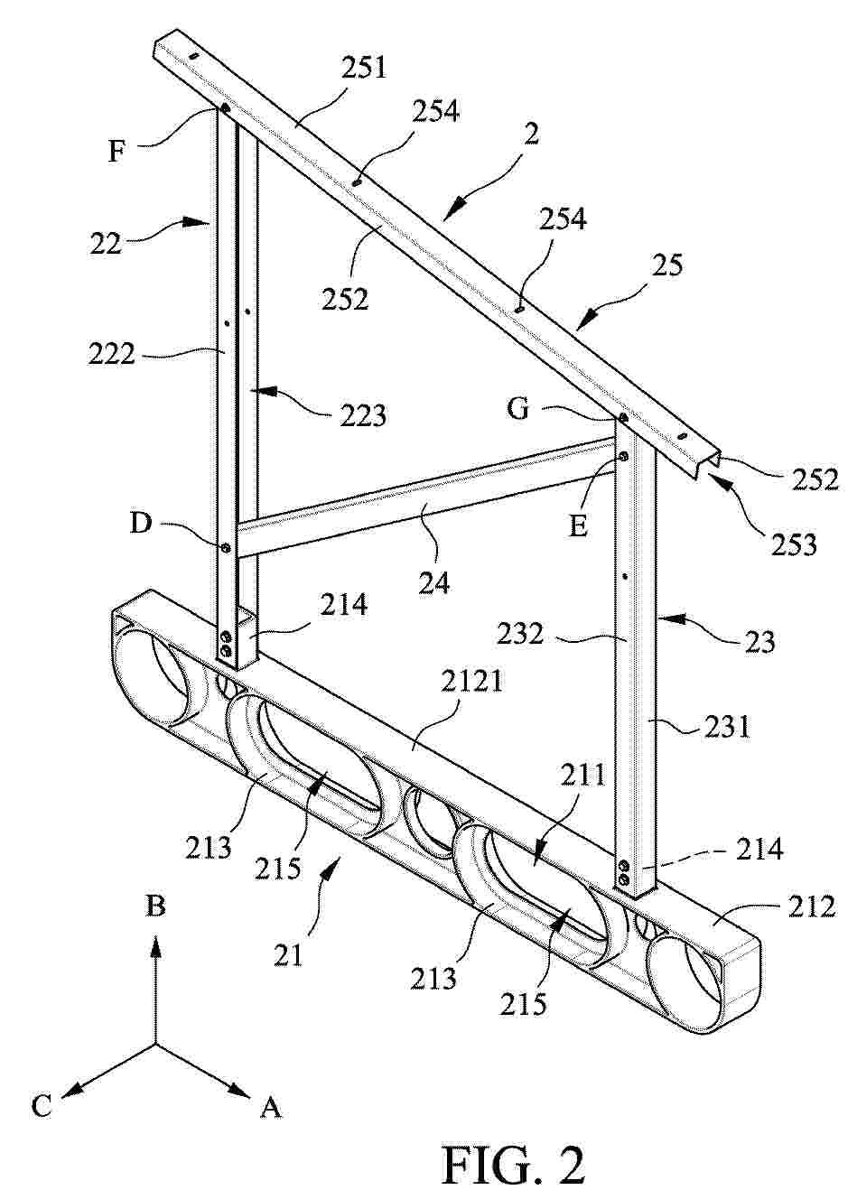
Resumen de: AU2024278637A1
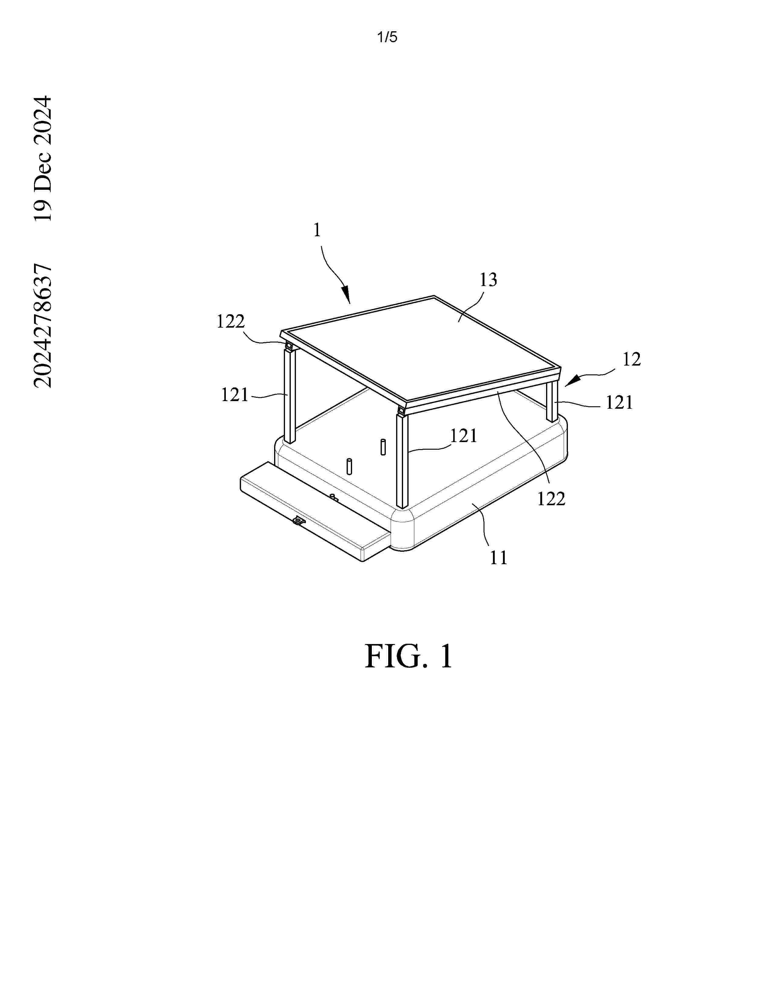
MOUNTING BRACKET FOR AN OFFSHORE PHOTOVOLTAIC MODULE A mounting bracket (2) for an offshore photovoltaic module includes a buoyancy body (21) extending along a lengthwise direction (A), a first pole (22) and a second pole (23) disposed on and extending from the buoyancy body (21) along a height direction (B) 5 and spaced apart from each other in the lengthwise direction (A), and a reinforcing beam (24) and a carrying beam (25) connected with the first and second poles (22, 23). Each of the first and second poles (22, 23) has a U-shaped cross-section for increasing the second moment of area, thereby improving the resistance to flexure of the first and second poles (22, 23). The reinforcing beam (24) extending in an inclined manner to 10 further improve the resistance to flexure in the lengthwise direction (A) so as to enhance the rigidity and durability of the entire offshore photovoltaic module assembly. (FIG. 2) MOUNTING BRACKET FOR AN OFFSHORE PHOTOVOLTAIC MODULE A mounting bracket (2) for an offshore photovoltaic module includes a buoyancy body (21) extending along a lengthwise direction (A), a first pole (22) and a second pole 5 (23) disposed on and extending from the buoyancy body (21) along a height direction (B) and spaced apart from each other in the lengthwise direction (A), and a reinforcing beam (24) and a carrying beam (25) connected with the first and second poles (22, 23). Each of the first and second poles (22, 23) has a U-shaped cross-section for increasing th
Resumen de: AU2024291327A1
A cell, a photovoltaic module, and a packaging method for a cell. The cell is a back-contact solar cell, and since a light receiving face of the cell is covered with a protection layer, the light receiving face of the cell can be prevented from being scratched due to the stacking and transportation of cells; and isolation paper does not need to be placed between two adjacent cells, thus reducing a fault rate of a production line.
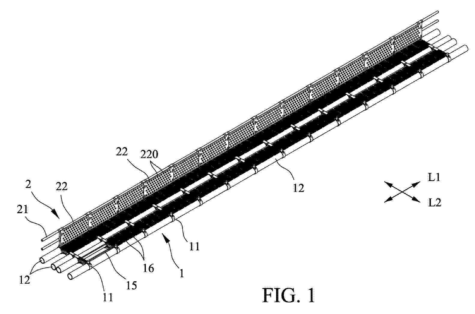
Resumen de: AU2025200182A1
WIND AND WAVE REDUCTION DEVICE FOR AN OFFSHORE SOLAR PHOTOVOLTAIC MODULE AND WIND AND WAVE REDUCTION SYSTEM INCLUDING THE SAME A wind and wave reduction device includes base seats (11) and base pipes (12). Each base seat (11) has two lateral ends and through holes (110) disposed between the lateral ends. Each base pipe (12) extends through a respective one of the through holes (110) of each of the base seats (11). Step plates (16) are disposed on support frames (15), and each of the support frames (15) is positioned between two adjacent ones of the base pipes (12). A lateral frame (21) is connected transversely to one of the lateral ends of each of the base seats (11). A blocking plate (22) is fixed to the lateral frame (21) and has air disturbing holes (220). (Fig. 1) WIND AND WAVE REDUCTION DEVICE FOR AN OFFSHORE SOLAR PHOTOVOLTAIC MODULE AND WIND AND WAVE REDUCTION SYSTEM INCLUDING THE SAME A wind and wave reduction device includes base seats (11) and base pipes (12). Each base seat (11) has two lateral ends and through holes (110) disposed between the lateral ends. Each base pipe (12) extends through a respective one of the through holes (110) of each of the base seats (11). Step plates (16) are 10 disposed on support frames (15), and each of the support frames (15) is positioned between two adjacent ones of the base pipes (12). A lateral frame (21) is connected transversely to one of the lateral ends of each of the base seats (11). A blocking plate (22) is fixed to the l
Resumen de: AU2025200186A1
SUPPORT SYSTEM FOR OFFSHORE SOLAR PHOTOVOLTAICS EQUIPMENT A support system for offshore solar photovoltaics equipment includes a float platform (1), float bodies (2), a ballast member (4), and a carrier frame (6) disposed on the float platform (1) and defining an accommodating space (61). The float platform (1) defines a plurality of limiting grooves (111) each of which extends in the longitudinal direction (A) and that are spaced apart from each other in a transverse direction (B) transverse to the longitudinal direction (A). The float bodies (2) are disposed in the limiting grooves (111) and protrude out of a bottom surface of the float platform (1). Each float body (2) surrounds and defines an inner space (21) adapted for a liquid or a gas to be filled therein. The ballast member (4) is connected to the float platform (1) and extends downwardly from the float platform (1) across bottom sides of the float bodies (2). (Figure 3) SUPPORT SYSTEM FOR OFFSHORE SOLAR PHOTOVOLTAICS EQUIPMENT A support system for offshore solar photovoltaics equipment includes a float platform (1), float bodies (2), a ballast member (4), and a carrier frame (6) disposed 5 on the float platform (1) and defining an accommodating space (61). The float platform (1) defines a plurality of limiting grooves (111) each of which extends in the longitudinal direction (A) and that are spaced apart from each other in a transverse direction (B) transverse to the longitudinal direction (A). The float bodies (2)
Resumen de: AU2023422671A1
An augmented logarithmic spiral antenna structure includes a first conductive layer, a. dielectric layer and a second conductive layer. The first conductive layer includes a first spiral arm and a plurality of second spiral arms. The first spiral arm includes a first initial radius. The second spiral arms are disposed around and connected to the first spiral arm, and each of the second spiral arms includes a second initial radius. The dielectric layer has a top surface and a bottom surface, and the top surface is connected to the first conductive layer. The second conductive layer is connected, to the bottom surface. A plurality of the second initial radii of the second spiral arms are different from each other, and different from the first initial radius.
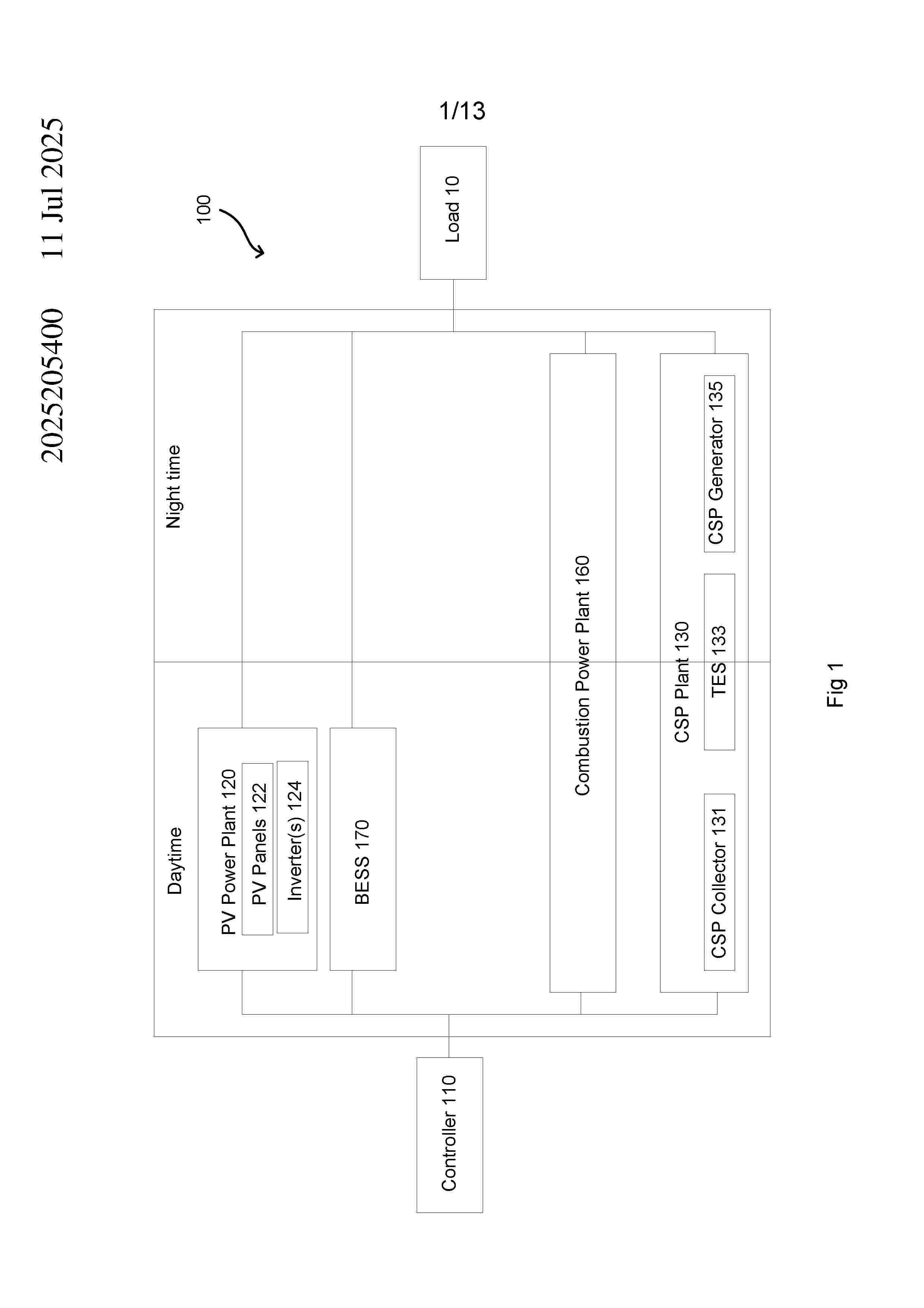
Resumen de: AU2025205400A1
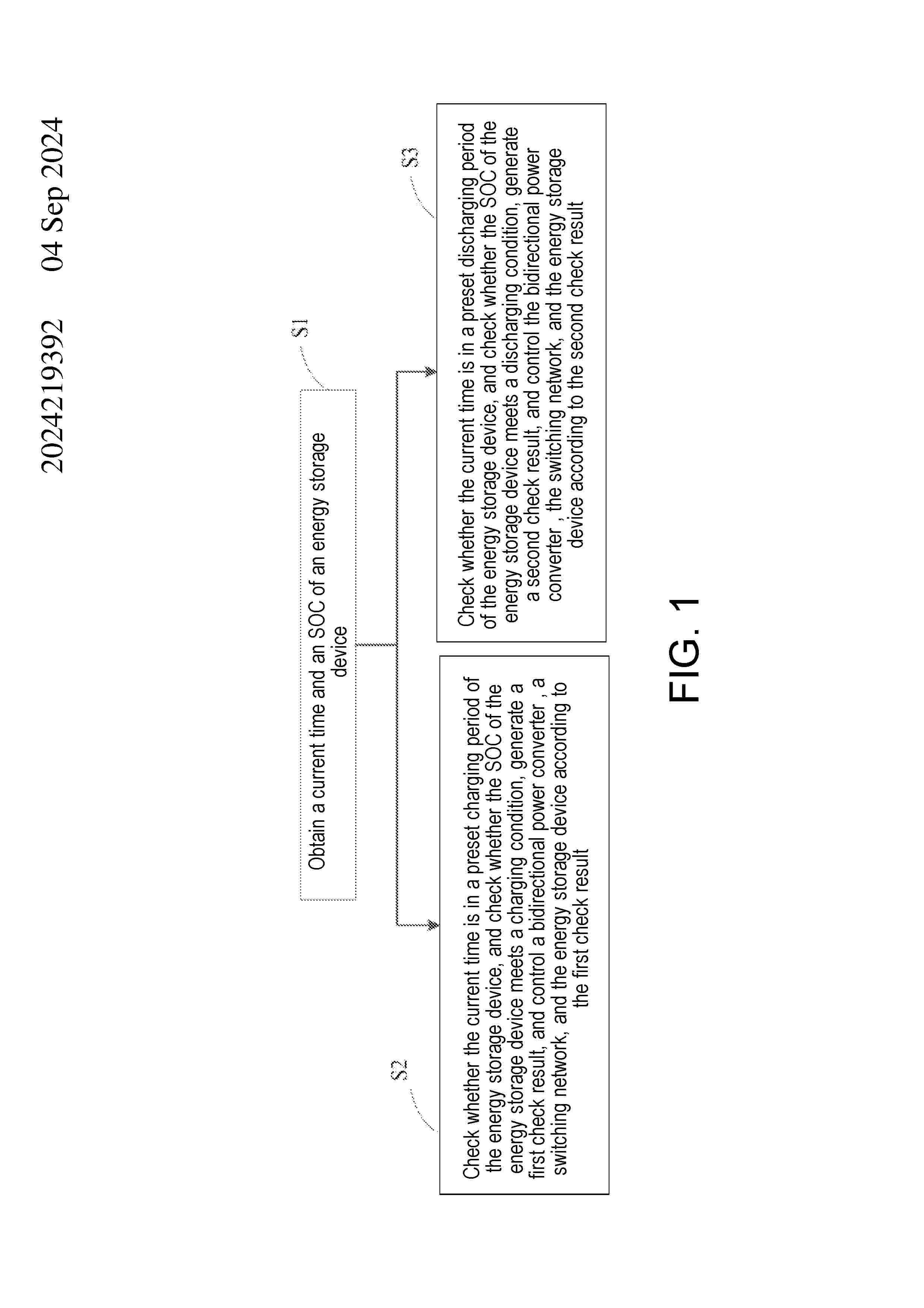
A method of simulating operation of a hybrid electrical power generation system having a battery energy storage system (BESS), a renewable energy (RE) power plant, and a combustion power plant, the method comprising: obtaining weather data for a location of the hybrid electrical power generation system, the weather data including a plurality of data points; and for each data point: determining an operating status of the BESS, the RE power plant, and the combustion power plant; in response to determining that an electrical power output of the RE power plant is sufficient to satisfy an electrical demand of the hybrid electrical power generation system and that a state of charge of the BESS is above a threshold value: dispatching the RE power plant to satisfy the electrical demand; in response to determining that the electrical power output of RE power plant is insufficient to satisfy the electrical demand, the state of charge of the BESS is above the threshold value, and the combustion power plant is not operating: dispatching the RE power plant to partially satisfy the electrical demand; and demanding the BESS to at least partially satisfy the electrical demand; and in response to determining that the electrical demand of the RE power plant is insufficient to satisfy the electrical demand, the state of charge of the BESS is above the threshold value, and the combustion power plant is operating: dispatching the RE power plant to partially satisfy the electrical demand; and dema
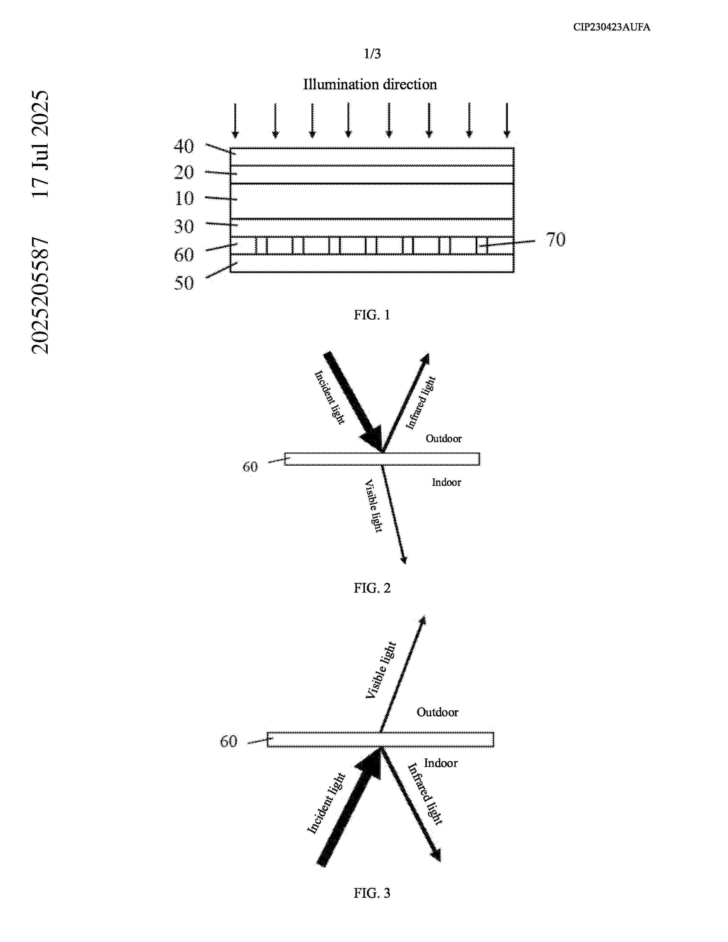
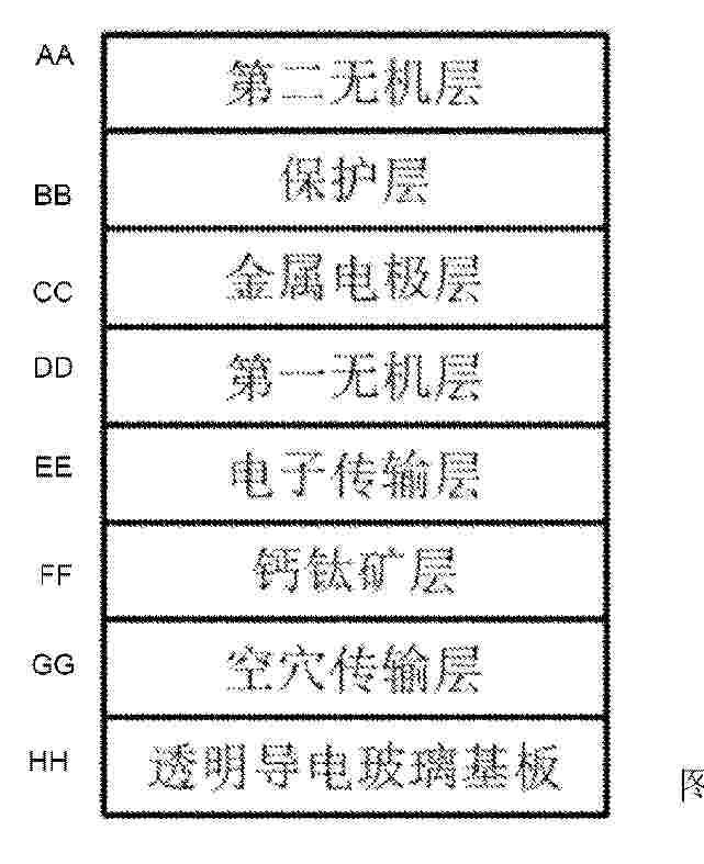
Resumen de: AU2025205587A1
The present application relates to the technical field of solar photovoltaics. Provided are a 5 perovskite cell and a photovoltaic module. The perovskite cell comprises a perovskite light absorption layer, a first carrier transport layer, a second carrier transport layer, a first transparent electrode layer, a second transparent electrode layer, and an optical adjustment layer, wherein the optical adjustment layer is arranged between the second carrier transport layer and the second transparent electrode layer; and the transmittance of the optical adjustment layer for visible light 10 is greater than or equal to a preset transmittance, and the reflectivity of the optical adjustment layer for infrared light is greater than or equal to a preset reflectivity. In the present application, the transmittance of an optical adjustment layer for visible light is greater than or equal to a preset transmittance, such that the efficiency of the perovskite cell and the lighting requirement of a building can be ensured; in addition, when the reflectivity of the optical adjustment layer for 15 infrared light is greater than or equal to a preset reflectivity, the requirements of the building for heat preservation, refrigeration, etc., can be ensured, thereby reducing the energy loss caused by the requirements of the building for heat preservation and refrigeration. ul h e p r e s e n t a p p l i c a t i o n r e l a t e s t o t h e t e c h n i c a l f i e l d o f s o l a r p h o t o v o l t a
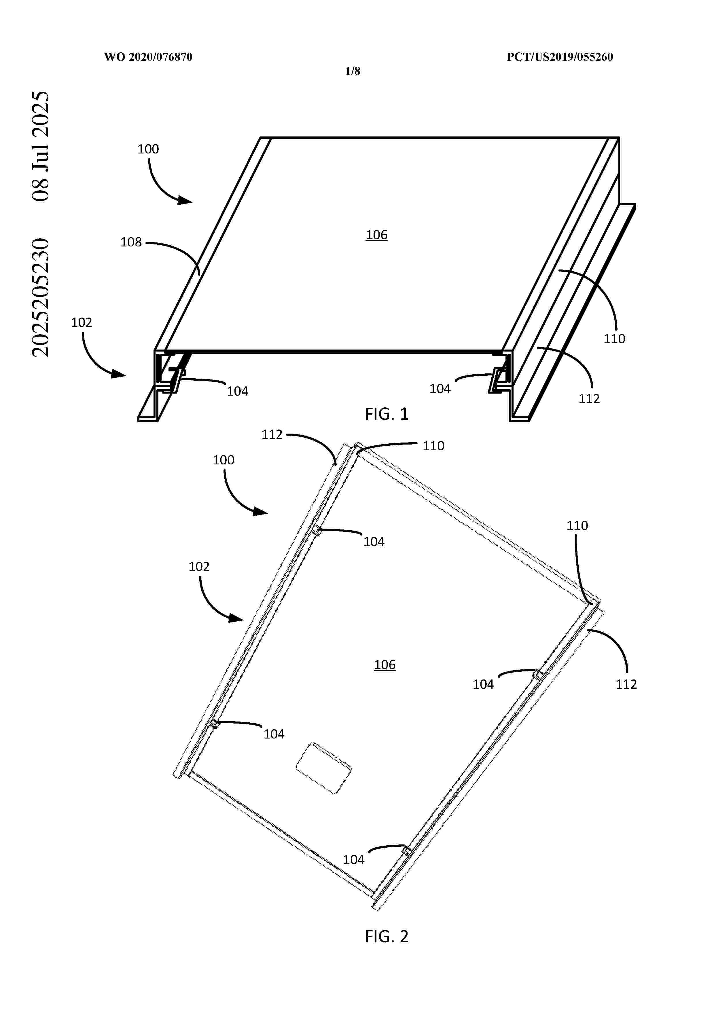
Resumen de: AU2025205230A1
Error! Unknown document property name..Error! Unknown document property name. Abstract A mounting system for mounting a solar panel assembly to a base assembly includes a panel support bracket, a base bracket and a clamp configured to exert a compressive force to hold the panel support bracket and the base bracket together. The clamp comprises a V- shaped clamp body that includes a pair of legs that are spring-loaded to oppose an approximation of the legs by an external compressive force. The clamp includes a pair of receiver slots, with each of the pair of receiver slots located on a corresponding one of the pair of legs. The pair of receiver slots collectively provides a clearance to admit the panel support bracket and the base bracket when the legs are compressed together. Abstract A mounting system for mounting a solar panel assembly to a base assembly includes a panel support bracket, a base bracket and a clamp configured to exert a compressive force to hold the panel support bracket and the base bracket together. The clamp comprises a V- shaped clamp body that includes a pair of legs that are spring-loaded to oppose an approximation of the legs by an external compressive force. The clamp includes a pair of receiver slots, with each of the pair of receiver slots located on a corresponding one of the pair of legs. The pair of receiver slots collectively provides a clearance to admit the panel support bracket and the base bracket when the legs are compressed together. Erro
Resumen de: DE102025101676A1
Aufgabe der Erfindung ist es modulare und leicht zu transportierende und leicht zu montierende Ständerelemente, sowie eine modulare und leicht zu montierende Ständerelementanordnung unter Verwendung der Ständerelemente für eine Ständeranordnung zu schaffen.Ständerelement (1) zur Aufstellung und Anordnung für zumindest ein Photovoltaikmodul (3) , wobei das Ständerelement (1) zumindest ein Betonformsteinelement (1) und zumindest ein Verbindungselement (2) aufweist, wobei das zumindest eine Betonformsteinelement (1) mittels zumindest eines Verbindungselementes (2) mit zumindest einem weiteren Betonformsteinelement (1) verbindbar ist und das zumindest eine Photovoltaikmodul (3) an den Betonsteinelementen anordbar ist, dadurch gekennzeichnet, dass das zumindest eine Betonformsteinelement (1) quaderförmige Grundform aufweist, wobei an dem zumindest einen Betonformsteinelement (1) zumindest eine Durchgangsöffnung (4) zwischen zwei gegenüberliegenden Außenflächen (5) vorhanden ist und sich zu einer zu den gegenüberliegenden Außenflächen (5) angrenzenden Außenfläche (6) erstreckt und wobei die Durchgangsöffnung (4) in Bezug oder Richtung zur angrenzenden Außenfläche (6) eine hinterschnittene Durchgangsaussparung (7) mit einem Querschnitt im Betonformsteinelement (1) bildet und dass das zumindest eine Verbindungselement (2) zumindest im Überlappungsbereich (8) mit der zumindest einen hinterschnittenen Durchgangsaussparung (7) einen komplementären Querschnitt aufw
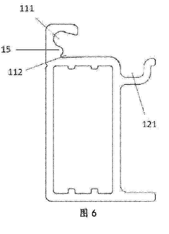
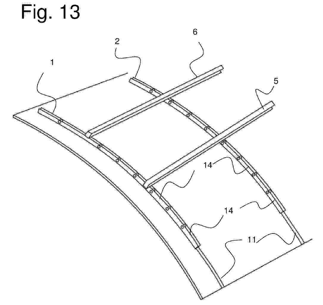
Resumen de: DE102024102720A1
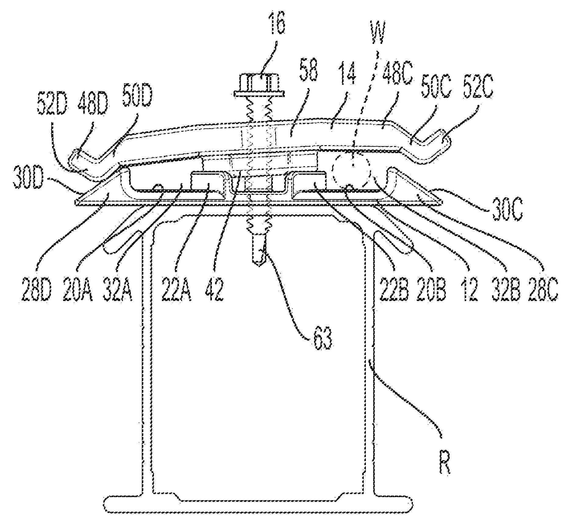
Vorrichtung (20) zur Montage eines Befestigungselements (48), welches zur Befestigung von Dachaufbauten, insbesondere von Kollektoren (64), auf einem aus Konterlattung (15) und Traglattung (14, 14a, 14b) bestehenden Dachstuhl dient, wobei die Vorrichtung (20) mindestens zwei Traglattungen (14a, 14b) überbrückt und das Befestigungselement (48) gegenüber der Ebene der Vorrichtung (20) im Winkel absteht und fußseitig mit der Vorrichtung (20) verbunden ist, wobei die Vorrichtung (20) mindestens an ihrem traufseitigen Ende (22) einen Montagewinkel (27) aufweist, mit dem sich die Vorrichtung (20) auf der Traglattung (14b) abstützt und mit dieser verbindbar ist.
Resumen de: DE102024102293A1
Die Erfindung betrifft ein Solarsystem zum Bereitstellen einer Photovoltaikanlage auf einem Wasserkörper, aufweisend eine Haltestruktur, eine Auftriebseinrichtung und eine Photovoltaikeinrichtung, wobei die Auftriebseinrichtung und die Photovoltaikeinrichtung mittels der Haltestruktur miteinander verbunden sind, die Haltestruktur in einer Schwimmlage der Auftriebseinrichtung mit einem hydrostatischen Auftrieb der Auftriebseinrichtung auf einer Wasseroberfläche des Wasserkörpers gehalten ist und die Haltestruktur die Photovoltaikeinrichtung in der Schwimmlage der Auftriebseinrichtung oberhalb der Wasseroberfläche zum Erzeugen von elektrischer Energie aus Sonnenlicht für Sonnenlicht zugänglich aufgenommen ist, wobei die Auftriebseinrichtung eine Auftriebsanpassungseinrichtung zum Verändern des hydrostatischen Auftriebs aufweist, wobei bei einem mittels der Auftriebsanpassungseinrichtung reduzierten hydrostatischen Auftrieb ein Absenken des Solarsystems und insbesondere der Photovoltaikeinrichtung in eine Tauchposition unterhalb der Wasseroberfläche ermöglicht ist. Des Weiteren betrifft die Erfindung ein Verfahren zum reversiblen Schützen einer Photovoltaikanlage.
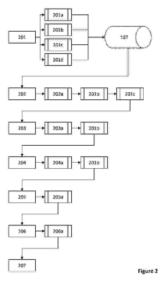
Resumen de: WO2025157418A1
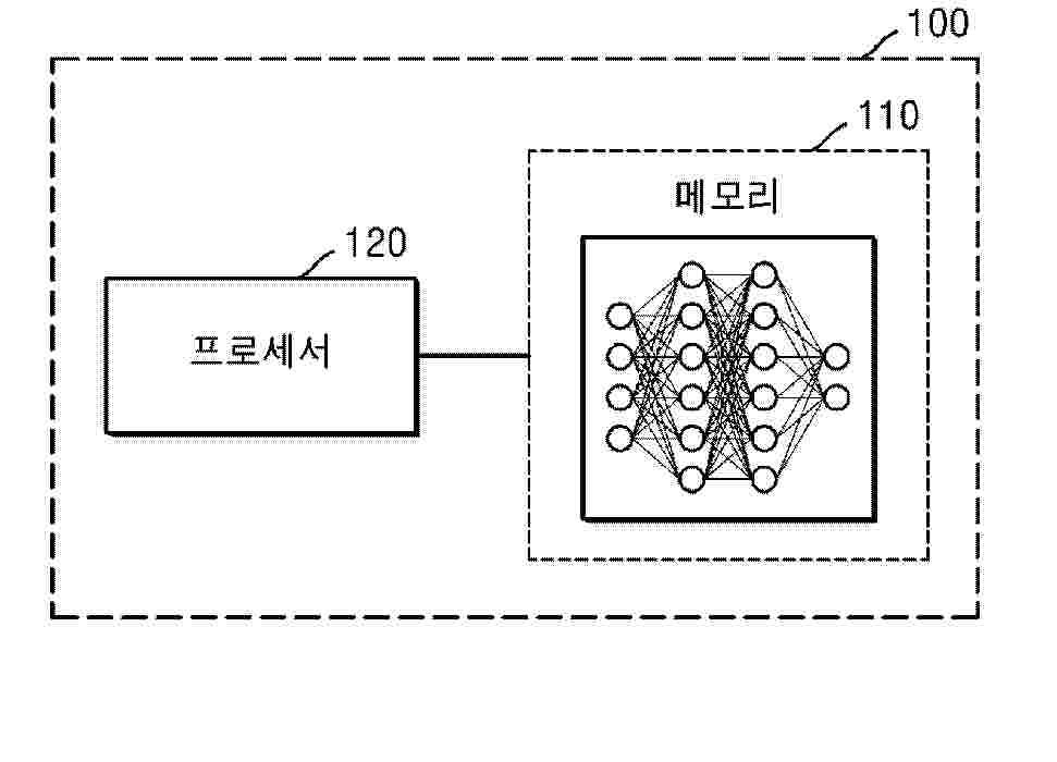
An apparatus and method for determining an optimised arrangement of a photovoltaic system for a geographic area are provided. Load data and solar irradiation data for the geographic area, and arrangements of pre-existing photovoltaic panels and potential arrangements for one or more additional photovoltaic panels, are acquired (201). Photovoltaic parameters are determined (202) based upon the arrangements of pre-existing photovoltaic panels and the potential arrangements for additional photovoltaic panels. Power consumption patterns based on the load data, and photovoltaic generation patterns based on the solar irradiation data, are determined (203). An objective function is determined (204) to meet load requirements with photovoltaic placement. The optimised arrangement of the photovoltaic system is determined (205) using the objective function and the photovoltaic parameters.
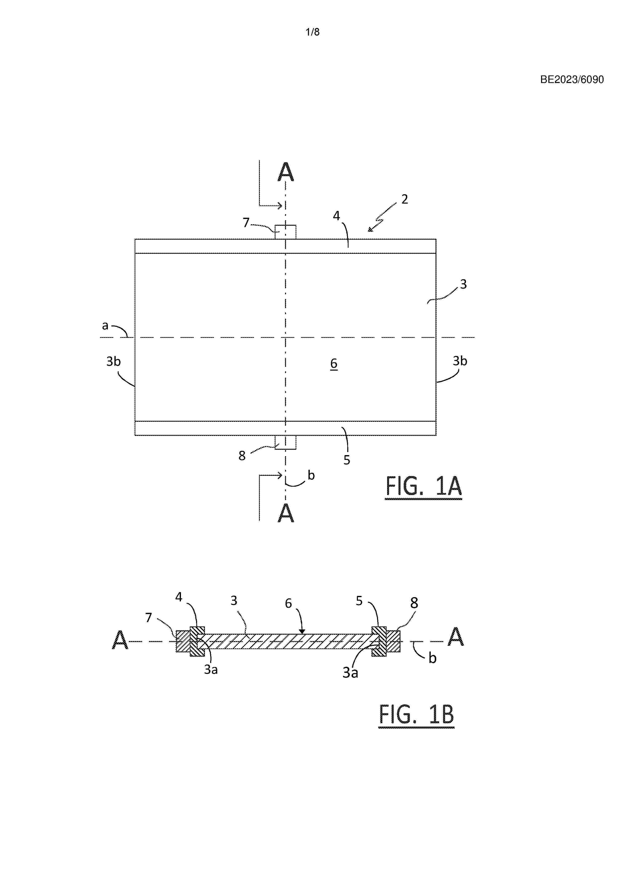
Resumen de: BE1032310A1
Deze uitvinding betreft een dakhaak (1) voor het bevestigen van een dakelement aan een dakconstructie en een samenstel van de dakhaak (1) en de dakconstructie. Deze dakhaak (1) omvat een onderste deel (2), een L-vormig bovenste deel (3), een middelste deel (6), dat het onderste deel (2) en het bovenste deel (3) met elkaar verbindt, en een voetsteun (7), die met een eerste uiteinde (8) verbonden is met de opstaande arm (5). Het bovenste deel (3) is voorzien van een rib-structuur (11) en een langgerekte bevestigingssleuf (12) voor het hier doorheen aanbrengen van bevestigingsmiddelen ter bevestiging van het dakelement, waarbij deze bevestigingssleuf (12) omringd is door de rib-structuur (11), om het dakelement (1) zo dicht mogelijk bij de dakconstructie (20) te laten aansluiten zodat externe natuurkrachten, die toenemen door het veranderende klimaat, minder invloed hebben op de stabiliteit van de bevestiging van het dakelement met behulp van dergelijke dakhaken (1).
Resumen de: BE1032309A1
Deze uitvinding betreft een zonnepanelen-systeem (1), omvattende een aantal zonnepanelen (2), (40), een verplaatsbare container (9), (52), een bevestigingslichaam (22) en minstens één flexibele draaginrichting (18,19), (41,42), dat naar keuze in een niet-gebruikstoestand kan gebracht worden waarbij de zonnepanelen (2), (40) zich in een compacte opstelling in de container (9), (52), bevinden, of in een gebruikstoestand kan gebracht worden waarbij het bevestigingslichaam (22) zich op een tussenafstand van de container (9), (52) bevindt en waarbij de flexibele draaginrichting (18,19), (41,42) verbonden is met de container en met het bevestigingslichaam en, zich tussen de container (9), (52) en het bevestigingslichaam (22) uitstrekkend, minstens een deel van de zonnepanelen (2), (40) draagt in een gebruiksopstelling. Deze uitvinding betreft ook een werkwijze voor het opstellen van dit zonnepanelen-systeem alsook het gebruik ervan voor het beïnvloeden van omgevingsparameters voor een agrarische toepassing.
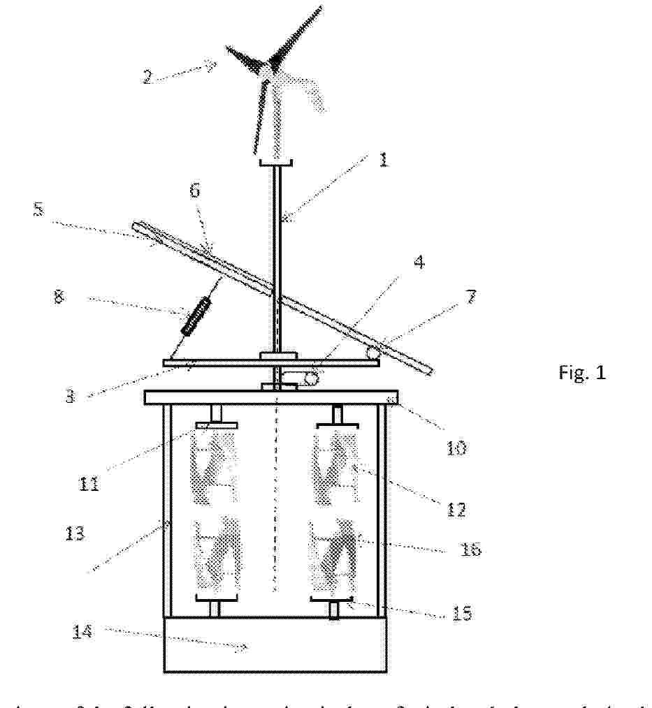
Resumen de: WO2025158470A1
The field of the technique of the following invention is that of wind and photovoltaic alternative energies. Normally these two solutions involve photovoltaic panels and turbines which are functionally distinct from each other and that also occupy different spaces. This invention proposes a unique support structure that allows the simultaneous use of a solar tracker and one or more turbines. The result is a hybrid device with all the equipment mounted on board that is simple to install.
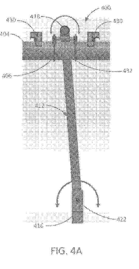
Resumen de: WO2025160121A1
A support structure (200, 300, 400, 500a, 500b, 600a, 600b) for solar trackers with thermal expansion mitigation includes a frame (212, 312, 412, 512, 612a, 612b) rotatably coupled to one or more ground piles (216, 316, 416, 516, 616a, 616b). The support structure (200, 300, 400, 500a, 500b, 600a, 600b) further includes a pivot bracket (206, 306, 406, 606a, 606b) rotatably coupled to a portion of the frame (212, 312, 412, 512, 612a, 612b) with the pivot bracket (206, 306, 406, 606a, 606b) including a pivot pin (244) to which torque tube clamps (232, 332, 432, 532) are rotatably coupled. The torque tube clamps (232, 332, 432, 532) are affixed to a torque tube (204, 304, 404, 504) and solar modules are affixed to the torque tube (204, 304, 404, 504) via one or more mounting brackets. Thermal expansion/contraction of the torque tube (204, 304, 404, 504) is translated into rotational movement of the frame (212, 312, 412, 512, 612a, 612b) relative to the one or more ground piles (216, 316, 416, 516, 616a, 616b) via the rotatable couplings including the pivot bracket (206, 306, 406, 606a, 606b). The rotational movement of the frame (212, 312, 412, 512, 616a, 612b) relative to the one or more ground piles (216, 316, 416, 516, 616a, 616b) enables the torque tube (204, 304, 404, 504) to expand/contract while mitigating mechanical stress of the support structure (200, 300, 400, 500a, 500b, 600a, 600b).
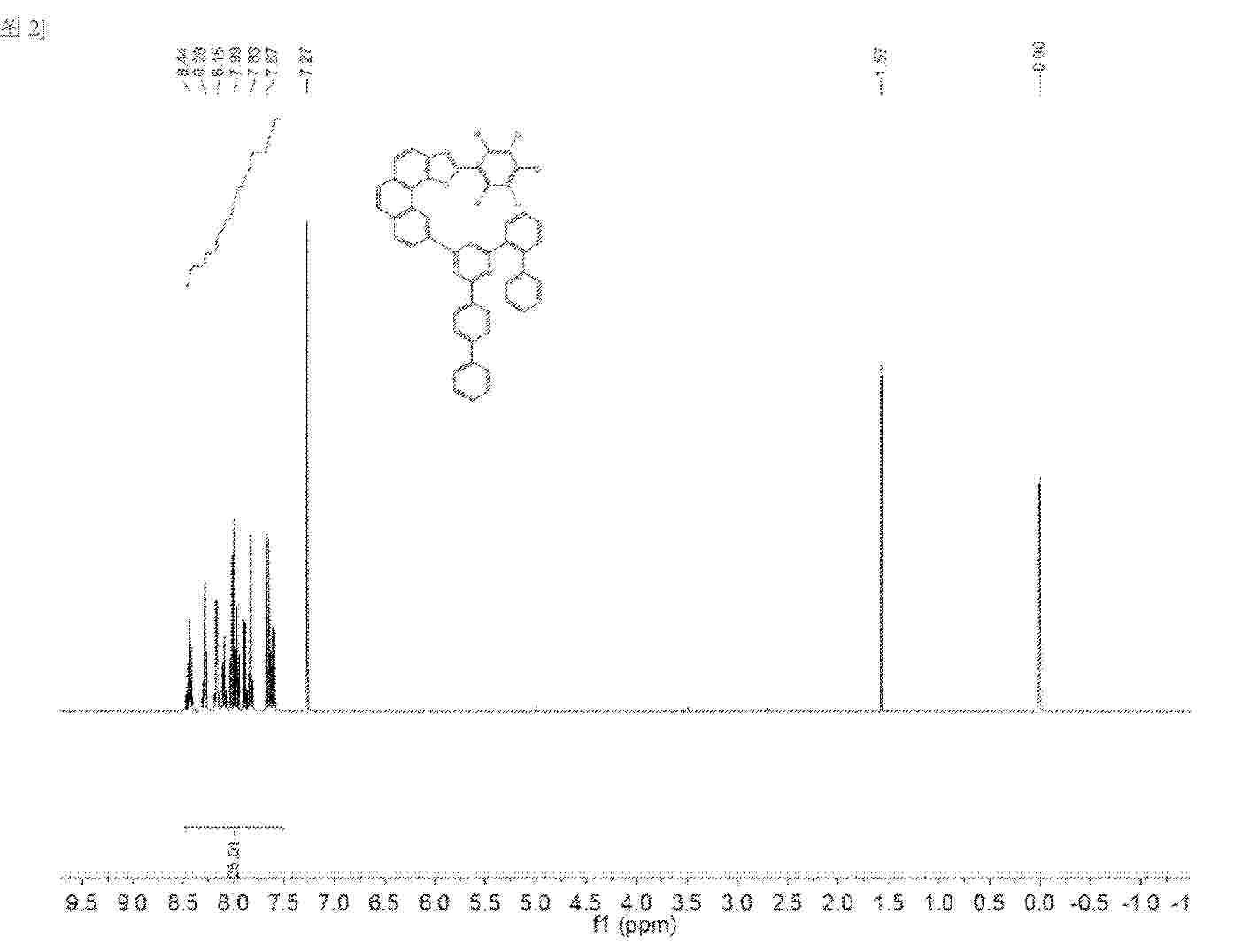
Resumen de: WO2025156843A1
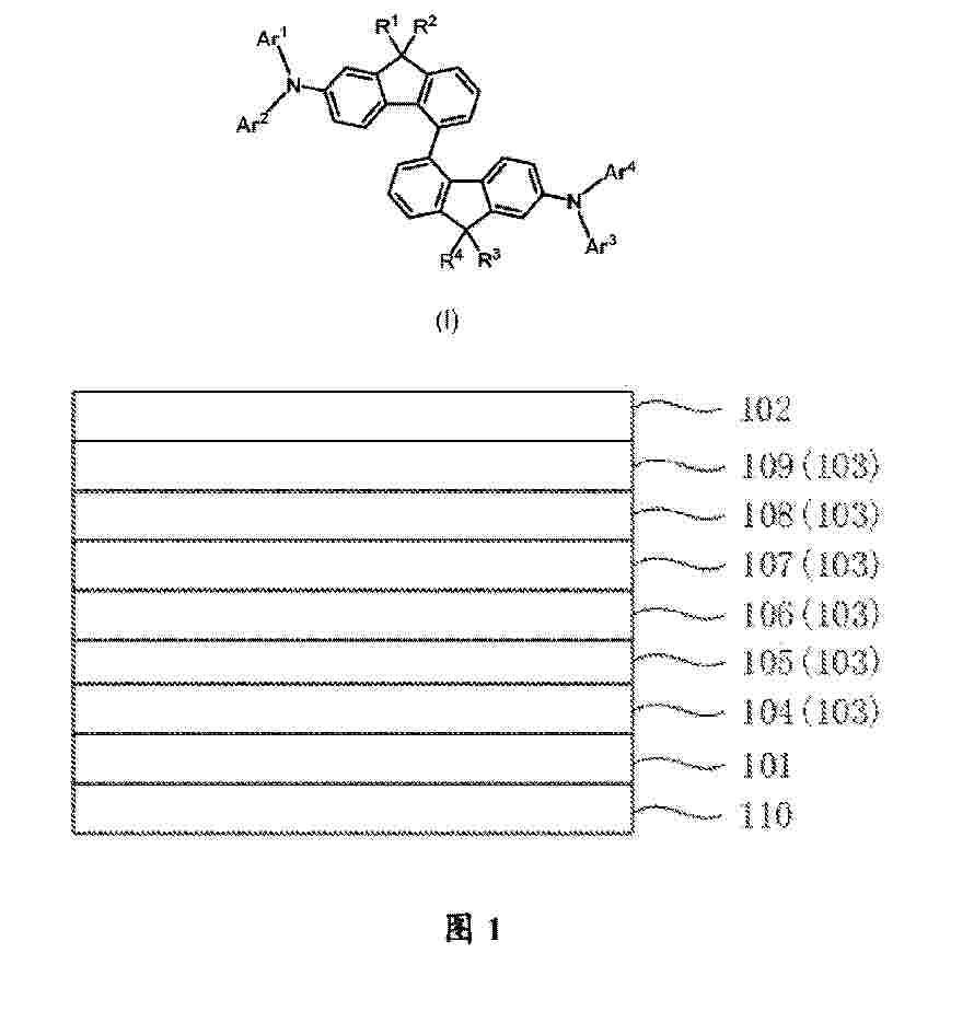
The present invention relates to the technical field of organic electroluminescent materials and provides an organic electroluminescent compound, host materials, and a light-emitting device and light-emitting apparatus comprising same. The host materials comprise an organic electroluminescent compound Lx and an organic electroluminescent compound Ly, wherein the mass ratio of Lx to Ly is 1:99-99:1, and the general structural formula of Lx and Ly are as shown in the description. In the present invention, a specific combination of host materials solves the problems in the prior art of low efficiency and short service life of a phosphorescent material applied to an organic electroluminescent device.
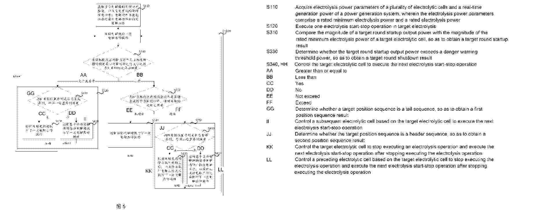
Resumen de: WO2025156736A1
Provided in the present application are a multi-electrolytic-cell series-parallel hydrogen production control method and a power generation system. The method in the present application comprises: acquiring electrolysis power parameters of a plurality of electrolytic cells and a real-time generation power of a power generation system; and then, on the basis of the plurality of electrolysis power parameters and the real-time generation power, controlling the plurality of electrolytic cells to sequentially and repeatedly execute electrolysis start-stop operations, wherein each electrolysis start-stop operation comprises: comparing the magnitude of a target round startup output power with the magnitude of a rated minimum electrolysis power of a target electrolytic cell; on the basis of a corresponding magnitude determination, performing subsequent control operations; and then in the subsequent control operations, performing a corresponding control operation by means of determining whether the target round startup output power exceeds a danger warning threshold power. Thus, the hydrogen production efficiency and flexibility of the plurality of electrolytic cells in the hydrogen production power generation system are improved, the stability of the hydrogen production power generation system is improved, and the service life of the hydrogen production power generation system is prolonged.
Resumen de: WO2025156558A1
The present application relates to the technical field of photovoltaics, and particularly discloses a photovoltaic module and a photovoltaic system. The photovoltaic module comprises: a laminated member and a frame fitted with the laminated member. The frame comprises a bearing portion and a blocking portion connected to the bearing portion. The bearing portion and the blocking portion surround to form an accommodating recess. In the thickness direction of the laminated member, the height of the top of the blocking portion is not higher than the height of a light-receiving surface of the laminated member. A first protrusion is provided in the accommodating recess, and the first protrusion divides the accommodating recess into a first accommodating recess and a second accommodating recess. In the thickness direction of the laminated member, there is a first distance L1 between the first protrusion and the top of the blocking portion, and there is a second distance L2 between the first protrusion and the top of the bearing portion, the distances satisfying 0.2≤L2:L1≤1. 2.
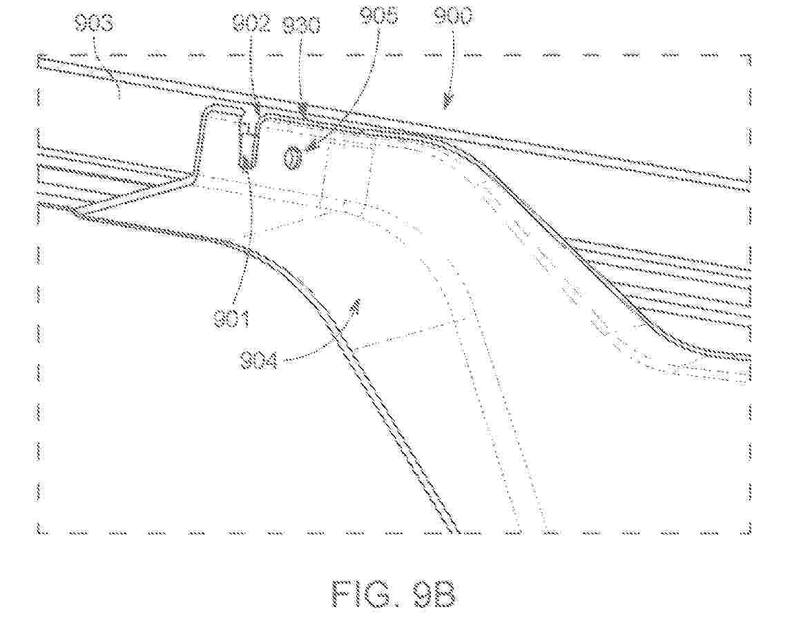
Resumen de: WO2025159944A1
A solar module frame coupling assembly (900) includes a solar module frame (908) and a rail (904). The solar module frame (908) includes a frame side portion (903) having a protruded guide structure (901). The rail (904) includes a first rail side (930) and a second rail side (931) that is opposite the first rail side (930). The second rail side (930) is configured to interface with a torque tube (14), and the first rail side (930) includes an alignment slot (902). The alignment slot (902) is configured to receive the protruded guide structure (901) to couple the solar module frame (908) to the rail (904).
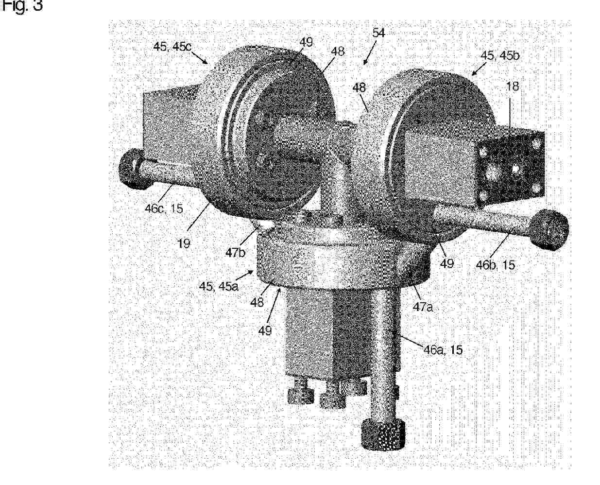
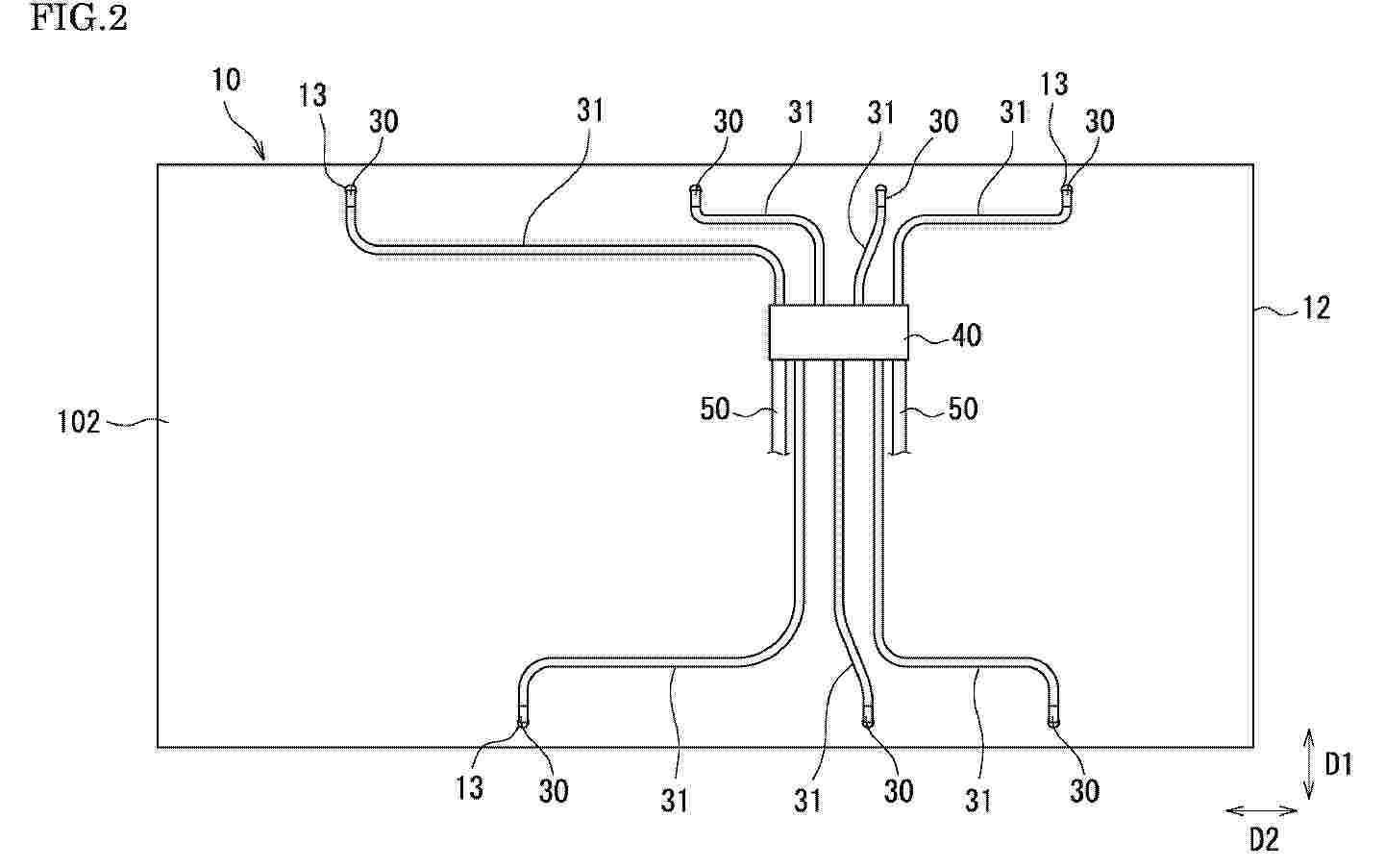
Resumen de: WO2025158085A1
The invention relates to a distributor unit (54) for a tracked solar installation, the distributor unit (54) comprising at least one first line section (11a) having a first rotating block (1, 1a) and at least one second line section (11b) having a second rotating block (1b), wherein the first line section (11a) is rotatably connected to the first rotating block (1a) and wherein the second line section (11b) is rotatably connected to the second rotating block (1b), wherein a first transfer unit (45a) having a first connection piece (46a) for connecting to a line for cleaning liquid (9) of a base element, in particular of a stand (42), of the solar installation is provided on the first rotating block (1a), and a second transfer unit (45b) having a second connection piece (46b) for connecting to a line for cleaning liquid (9) of a first supporting arm (43) of the solar installation is provided on the second rotating block (1b), wherein the second transfer unit (45b) is connected to the first transfer unit (45a) via at least one first pipe connection (47a) running outside the first line section (11a) and outside the second line section (11b).
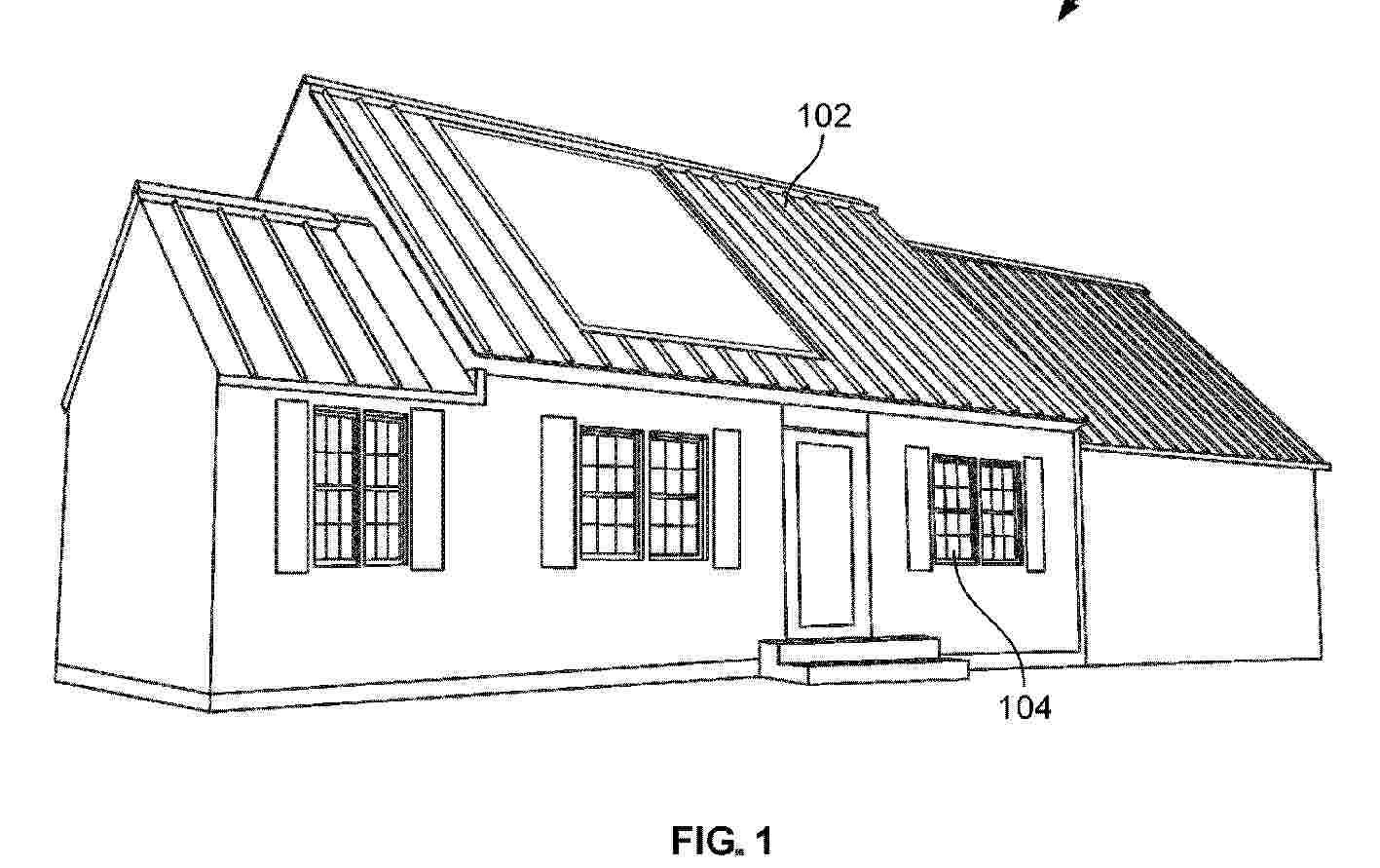
Resumen de: WO2025157678A1
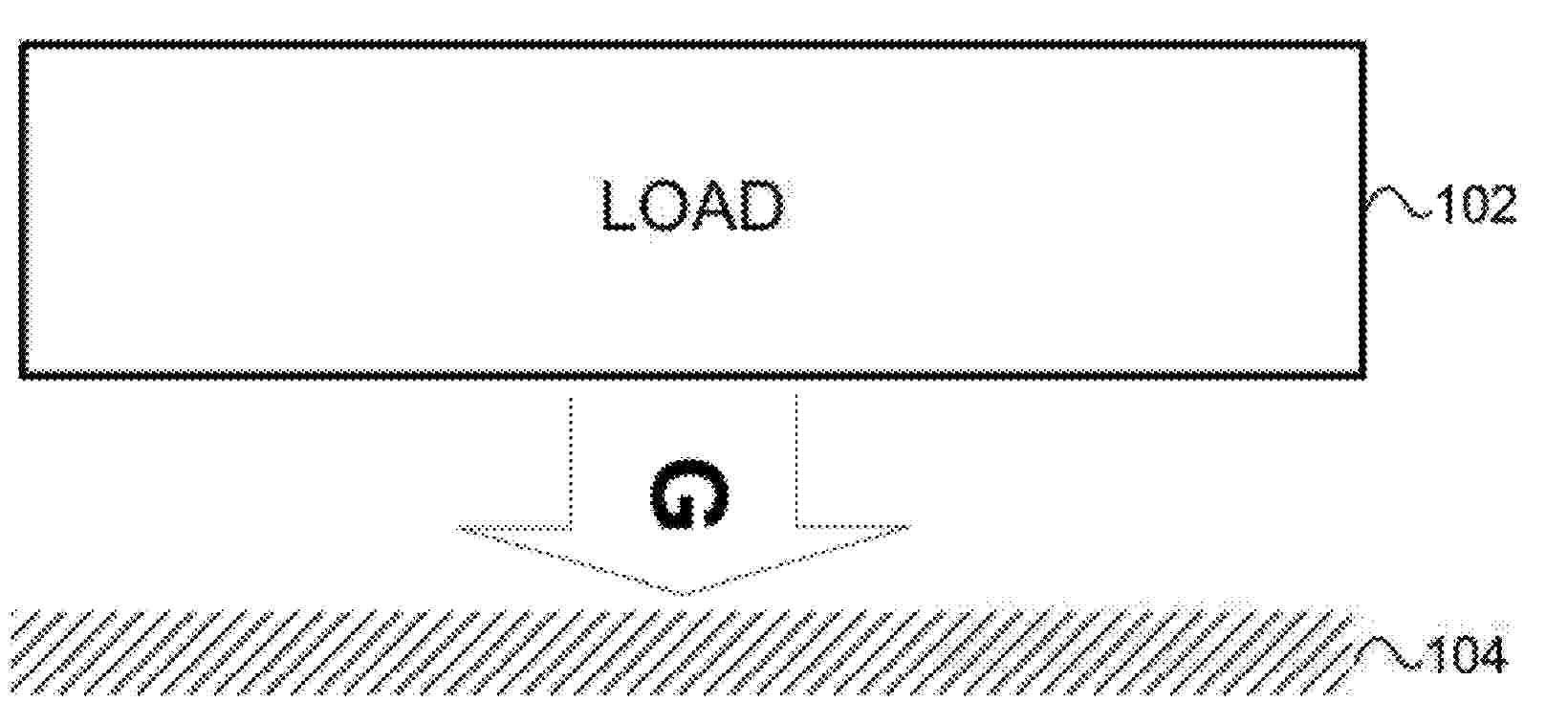
A barrier system (102, 200) includes a frame assembly (208) including a plurality of structural members; and a plurality of panels coupled together with the frame assembly and configured to form a roof or facade of a building (100) that defines a human-occupiable space. The plurality of panels includes at least one photovoltaic (PV) panel (202) configured to generate direct current electrical power in response to receiving solar energy; and at least one metallic (204) or composite panel (206).
Resumen de: WO2025156014A1
A solar energy collection assembly comprising: a first spherical mirror assembly having a first reflective mirror surface with a centre located above the first spherical mirror, a radius of curvature R1 and a focus located on a first movable axis which passes through the centre of the first reflective mirror surface and through the sun with a first sunlight absorbing receiver adapted to be movably positioned to substantially align with the first movable axis in a plurality of positions for receiving and absorbing reflected light when sunlight is reflected by the first reflective mirror surface; a second spherical mirror assembly arranged above the reflective surface of the first spherical mirror assembly in a non-concentric configuration relative to the first spherical mirror assembly, the second spherical mirror having a second reflective mirror surface with a centre located away from the second spherical mirror, a radius of curvature R2 and a focus located on a second movable axis which passes through the centre of the second spherical mirror and through the sun with a second sunlight absorbing receiver adapted to be movably positioned to substantially align with the second movable axis in a plurality of positions for receiving and absorbing reflected light when sunlight is reflected by the second spherical mirror; and a rotation mechanism for rotating the combination of the first and second spherical mirror assemblies about a common axis to allow the reflective surface of
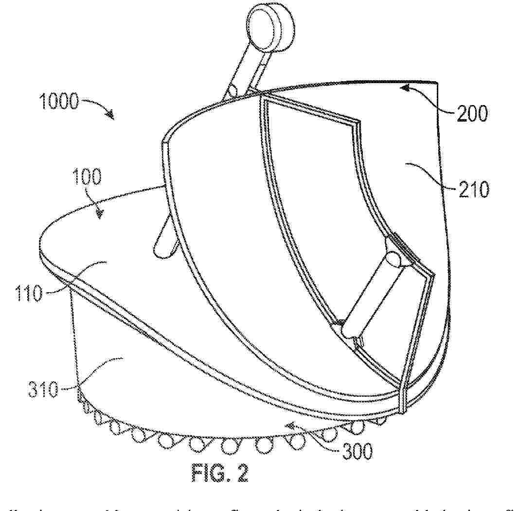
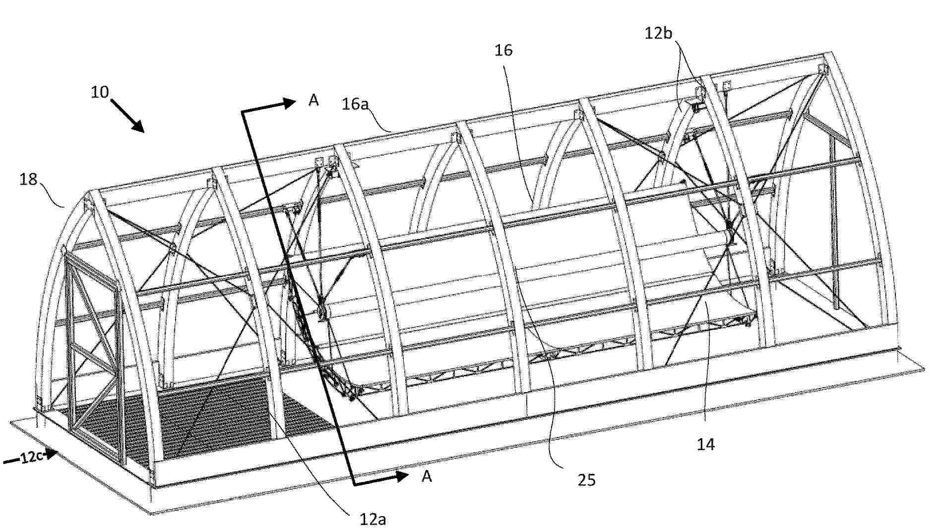
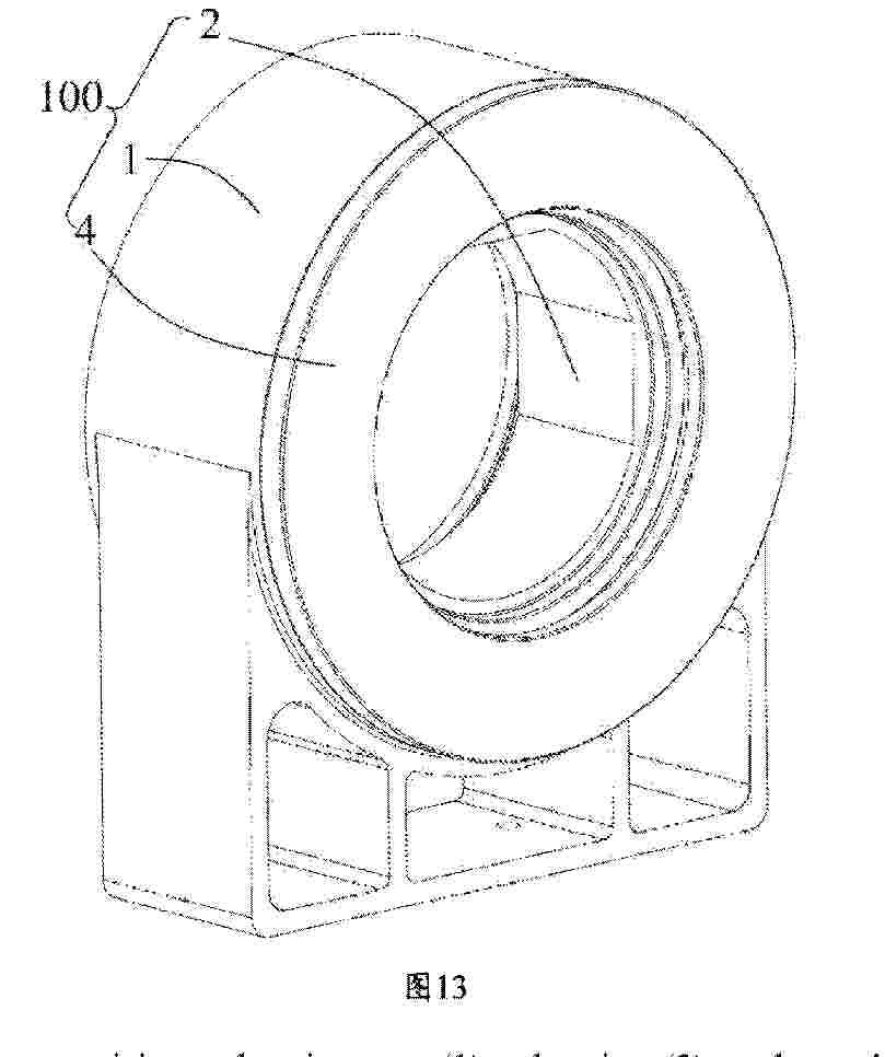
Resumen de: US2025244053A1
The invention relates to enclosed solar parabolic trough reflector systems for thermal heat generation that can ultimately be used in various applications. The system includes a modular dual arch building design with a transparent building envelope and a reflector assembly connected within the building through a bearing assembly. The system is particularly suited for solar heat collection in harsh environment.
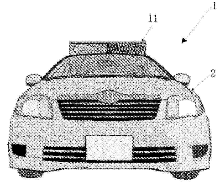
Resumen de: US2025243707A1
A modular headrail-mounted automation system for wand-operated horizontal blinds optionally includes a main module with two bilaterally-disposed interfaces to auxiliary modules or cables. Optionally, the system includes a photovoltaic panel whose photosensitive surface is located on the room side of the host blind and faces the host blind's slats. Optionally, the system includes a controller to tilt the slats of the host blind over a range in which the maximum amount of slat closure is reduced when the system is powered by a photovoltaic source. Optionally, the maximum amount of slat closure is dependent upon the level of charge in an energy-storage device charged by a photovoltaic source.
Resumen de: US2025242700A1
A wind-solar hybrid power generation apparatus includes a square-shaped casing that opens at a front and a rear, a power generation motor that is installed inside the casing, and a solar power generation panel that is placed on an upper surface of the casing. The power generation motor includes a main body that is fixed to a bottom surface of the casing or at a position where the casing is installed, a rotation shaft that is rotatably provided in the main body, a coupling rod that is connected to the rotation shaft and bent downward in a hook shape, and a blade that is continuously provided to the coupling rod. The wind-solar hybrid power generation apparatus has a low height by rotating the blade horizontally with respect to a surface of the position where the casing is installed.
Resumen de: US2025243339A1
Composite materials that include a polymer matrix and a metal halide perovskite. The metal halide perovskite may be a lead-free metal halide double perovskite. Devices that include a layer of a composite material, a first electrode, and a second electrode. Methods of forming composite materials and devices, including methods that include printing one or more layers with a 3D printer.
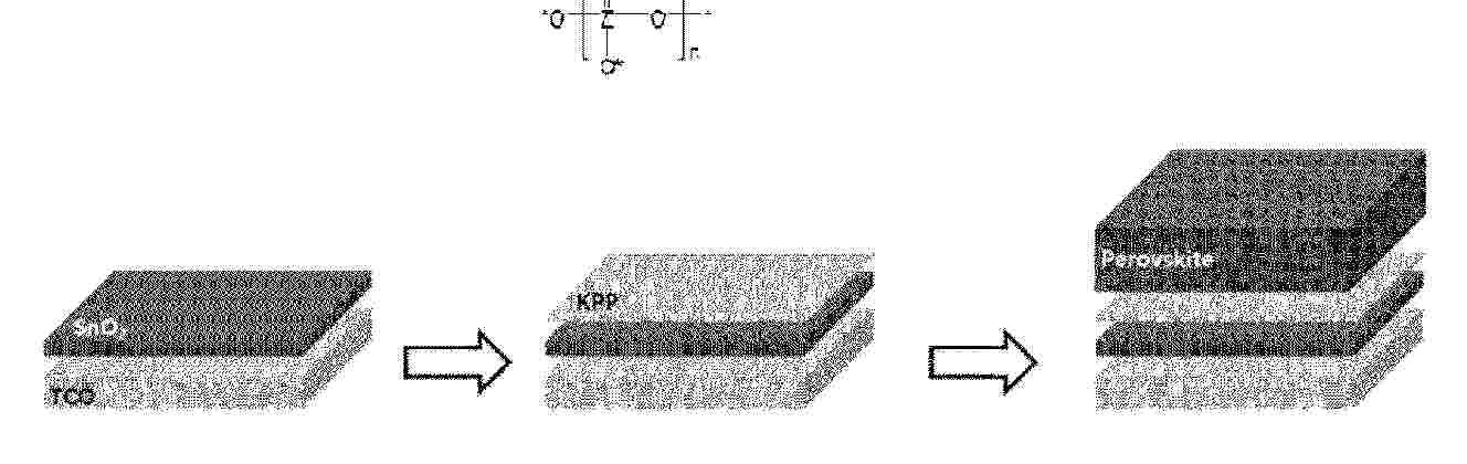
Resumen de: WO2025159629A1
The present invention relates to a perovskite photoelectric device having high light transmittance and photoelectric conversion efficiency and a method for manufacturing the perovskite photoelectric device, the method comprising: (S1) a charge transport layer complex preparation step of stacking an intermediate layer containing an intermediate layer compound on a charge transport layer; and (S2) a step of stacking a perovskite thin film on the intermediate layer, wherein the intermediate layer compound contains a repeating unit satisfying chemical formula 1 below. (Chemical formula 1) (In chemical formula 1, Z is at least one selected from the group consisting of phosphorus (P), arsenic (As), antimony (Sb), and bismuth (Bi), and n is a positive integer of 1 or greater.)
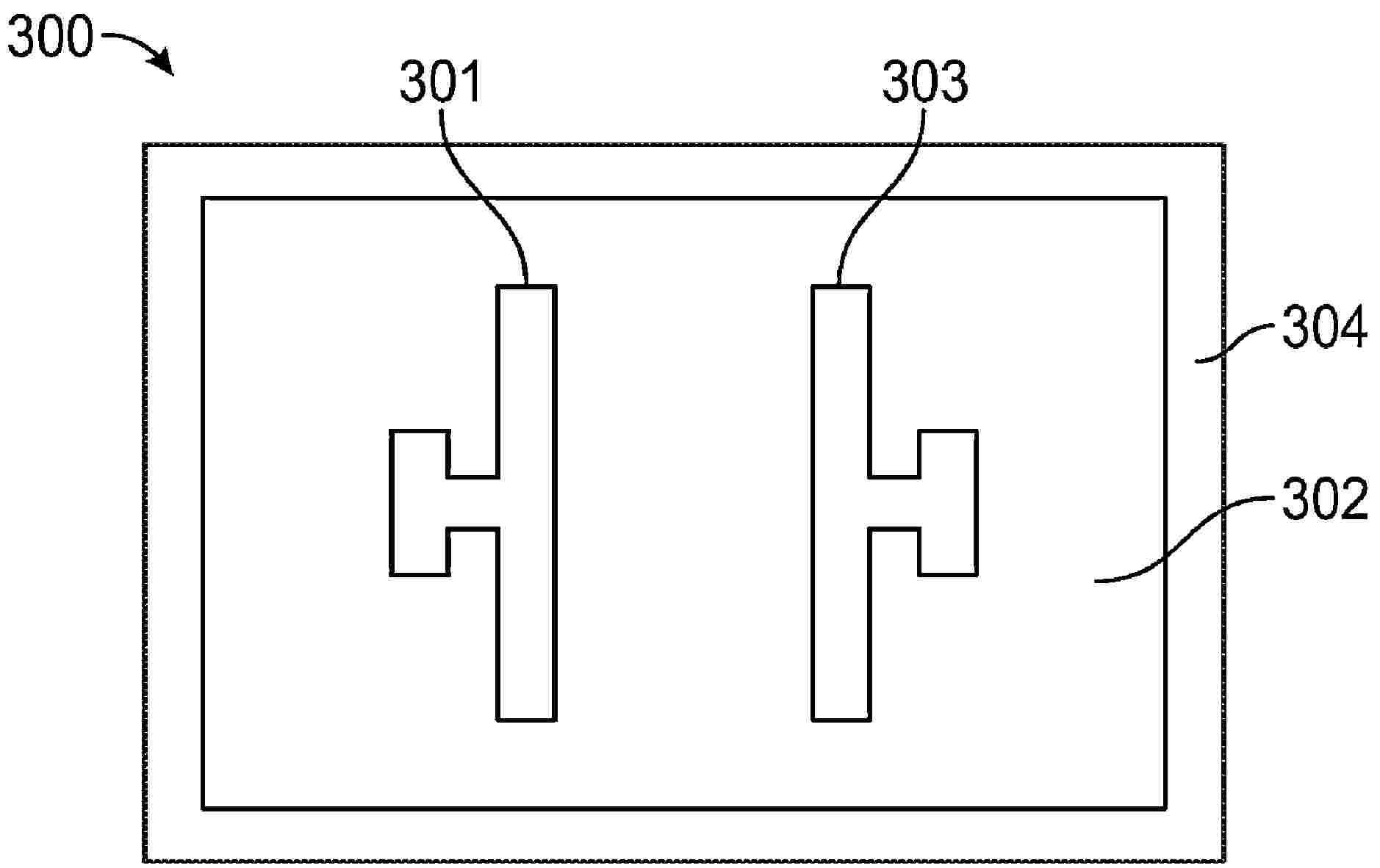
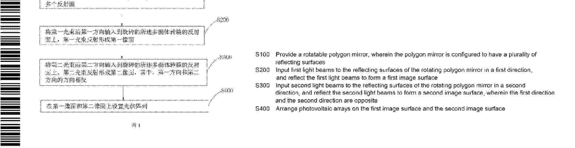
Resumen de: WO2025156893A1
Disclosed in the present invention are a laser-based power receiving method and a power transmission system. The laser-based power receiving method comprises the following steps: providing a rotatable polygon mirror, wherein the polygon mirror is configured to have a plurality of reflecting surfaces; inputting first light beams to the reflecting surfaces of the rotating polygon mirror in a first direction, and reflecting the first light beams to form a first image surface; inputting second light beams to the reflecting surfaces of the rotating polygon mirror in a second direction, and reflecting the second light beams to form a second image surface; and arranging photovoltaic arrays on the first image surface and the second image surface. In the laser-based power receiving method of the present invention, the photovoltaic arrays are arranged on the first image surface and the second image surface, the polygon mirror can continuously scan the photovoltaic arrays by reflecting the first light beams and the second light beams, and two arc-shaped photovoltaic receiving surfaces are formed on the polygon mirror, thereby significantly increasing the area of the photovoltaic receiving surfaces, and achieving the effects of increasing the power transmitted via laser and improving the overall output power.
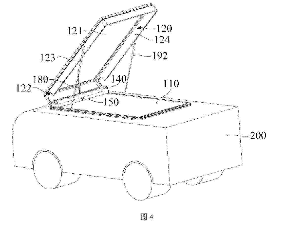
Resumen de: WO2025156917A1
Disclosed are a vehicle rooftop tent (100) and a vehicle. The vehicle rooftop tent (100) comprises a base (110), a cover body assembly (120), a tarpaulin (130), a ventilation pipe (140), and an energy storage assembly (150); the cover body assembly (120) is connected to the base (110); the ventilation pipe (140) is connected to the base (110) or the cover body assembly (120); a ventilation hole (141) is formed in the cover body assembly (120) or the base (110); the ventilation hole (141) is used for providing clearance for the end portion of the ventilation pipe (140); the energy storage assembly (150) is located in the ventilation pipe (140).
Resumen de: WO2025156966A1
Provided in the present application are a power conversion apparatus and a control method therefor. The power conversion apparatus comprises a first DC/DC conversion circuit, a second DC/DC conversion circuit, a DC/AC conversion circuit and a controller, wherein the first DC/DC conversion circuit is connected in parallel to an output of the second DC/DC conversion circuit; when the power conversion apparatus switches from a non-power-limited state to a power-limited state, the controller adjusts an input voltage of the first DC/DC conversion circuit to a first voltage, and adjusts an input voltage of the second DC/DC conversion circuit to a second voltage, so as to reduce both an input power of the first DC/DC conversion circuit and an input power of the second DC/DC conversion circuit; and the first voltage is greater than the input voltage of the first DC/DC conversion circuit when the power conversion apparatus is in the non-power-limited state, and the second voltage is greater than the input voltage of the second DC/DC conversion circuit when the power conversion apparatus is in the non-power-limited state. Therefore, the power generation of a power conversion apparatus can be improved.
Resumen de: US2025242707A1
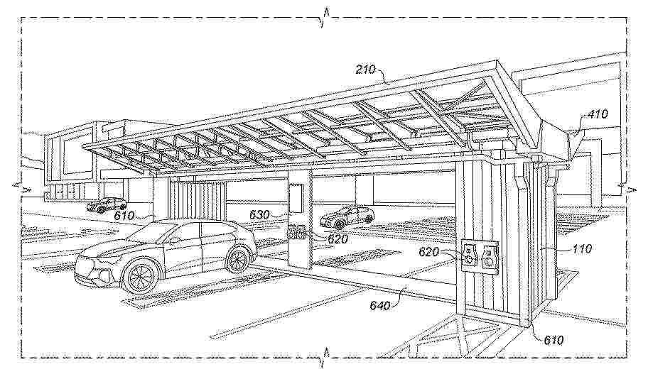
A charging station for an electric vehicle (EV) comprising a container having an electric vehicle (EV) charging port for charging the EV and a first photovoltaic (PV) panel coupled to the container, wherein the first PV panel is movable from a first orientation, in which the plane of the first PV panel is substantially parallel to a first side wall of the container, to a second and third orientation in which the first PV panel extends away from the first side of the container, such that in the second orientation the plane of the first PV panel is orientated at an angle in a downward direction from the top of the container and in the third orientation the plane of the first PV panel is orientated at an angle in an upward direction from the top of the container, wherein the first PV panel is arranged to be electrically coupled to the EV charging port.
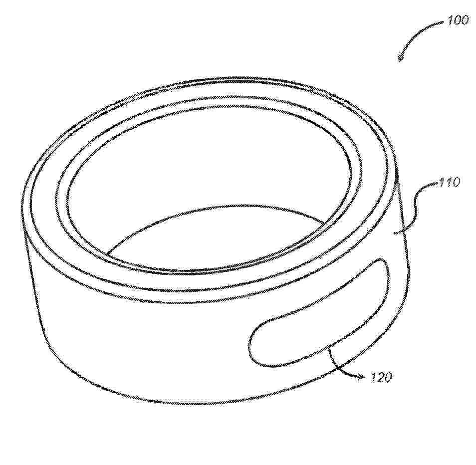
Resumen de: US2025244793A1
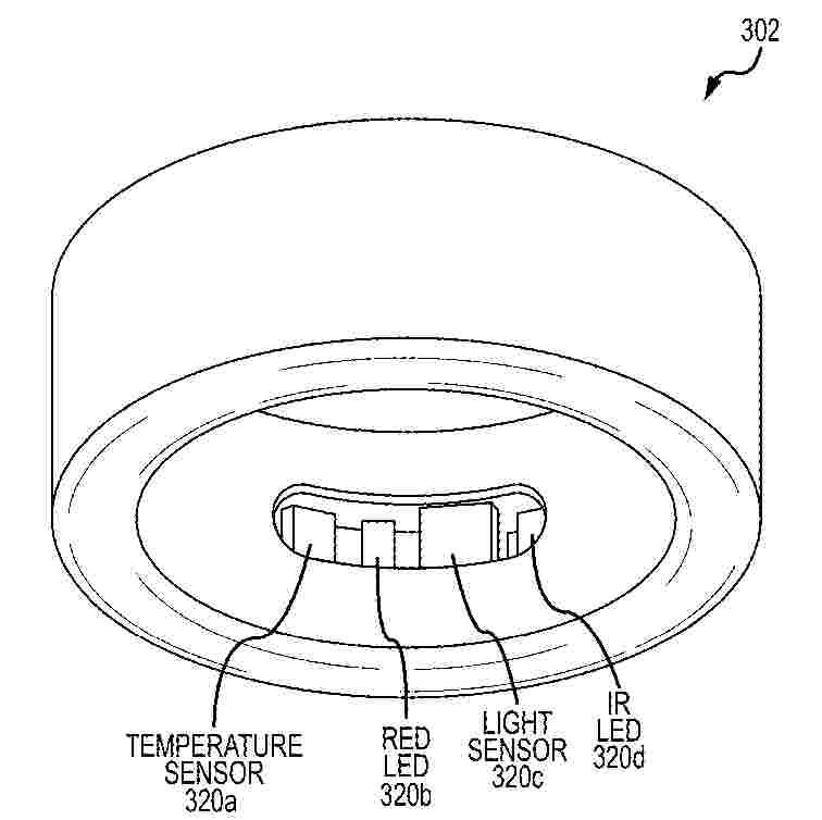
A finger-worn wearable ring device may include a ring-shaped housing, a printed circuit board, and a sensor module that includes one or more light-emitting components and one or more light-receiving components. The wearable ring device may further include a communication module configured to wirelessly communicate with an application executable on a user device.
Resumen de: US2025248296A1
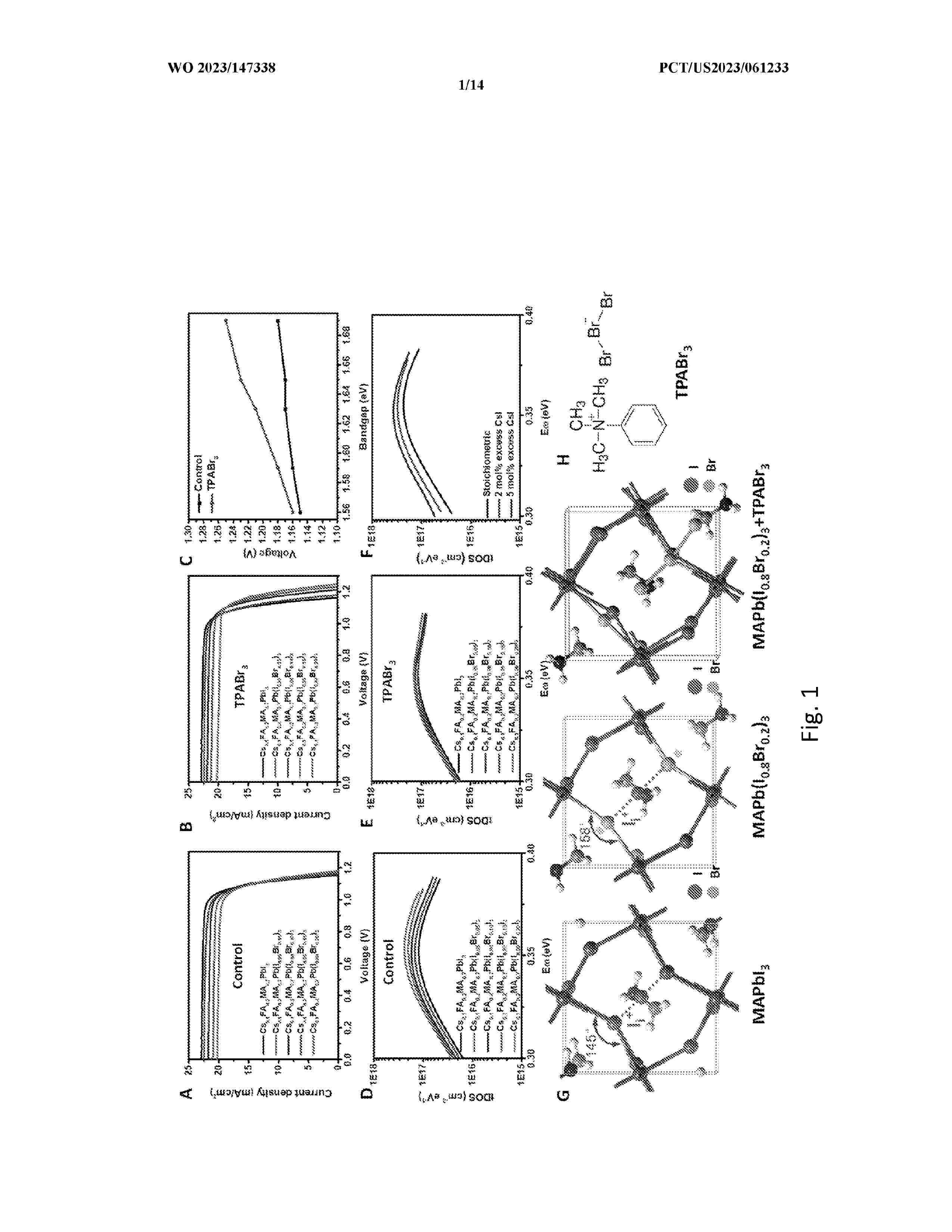
Described herein are perovskite ink solutions comprising a composition of Formula I (APbI3-zBrz), a tribromide salt, and a solvent, wherein z is defined herein. Further described are perovskite films prepared using the ink solutions, methods for preparing the perovskite films, and use of the films in wide band gap single junction and tandem solar cells. As shown herein, solar cells fabricated using the perovskite films prepared from ink solutions comprising a tribromide salt achieve enhanced efficiency compared to solar cells comprising a perovskite film prepared without the tribromide salt.
Resumen de: US2025248136A1
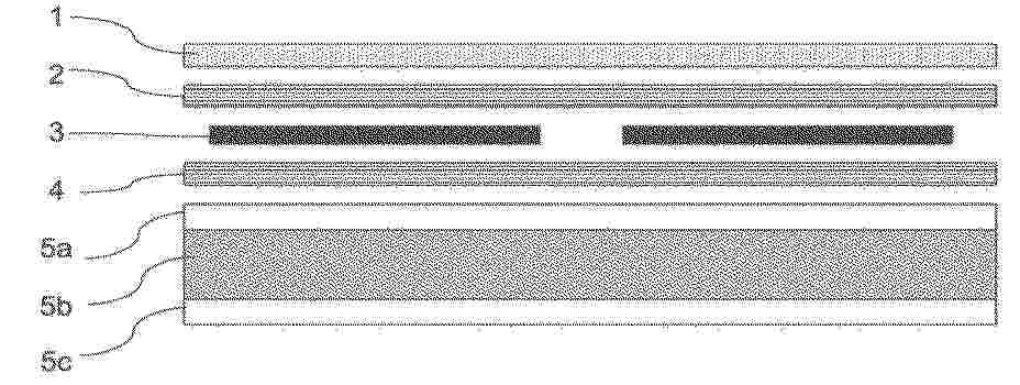
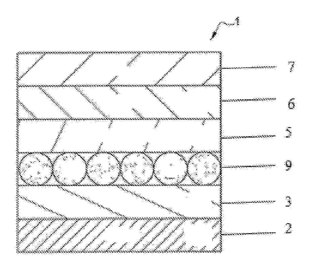
The invention relates to a photovoltaic module comprising (a) a front layer (1) arranged on the sunlight facing side of the photovoltaic module, wherein the front layer (1) comprises a first polypropylene composition, comprising a polypropylene, wherein the transmission of the front layer for light in the wavelength range of 350 nm to 1200 nm is on average at least 65% as compared to a situation without the front layer as determined according to ASTM D1003-13, (b) a sealing layer (2,4) which at least partly encapsulates a plurality of photovoltaic cells (3), wherein the sealing layer (2, 4) comprises a polyolefin elastomer composition comprising an ethylene-α-olefin copolymer and (c) a back layer (5), wherein the back layer (5) comprises a first reinforced polypropylene layer comprising a second polypropylene composition comprising a polypropylene and optionally a reinforcing filler, wherein the sealing layer is arranged between the front layer and the back layer.
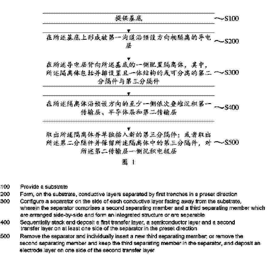
Resumen de: US2025248137A1
A solar cell assembly preparation method. In the process of preparing a conductive layer, several conductive layers separated by a first trench are formed on the substrate. After the conductive layers are formed, the separating function of second separating members and the separating function of third separating members are respectively utilized to ensure that the functional layer groups formed on one side of the conductive layers are separated by and located on two sides of an entirety formed by the second separating members and the third separating members.
Resumen de: US2025248134A1
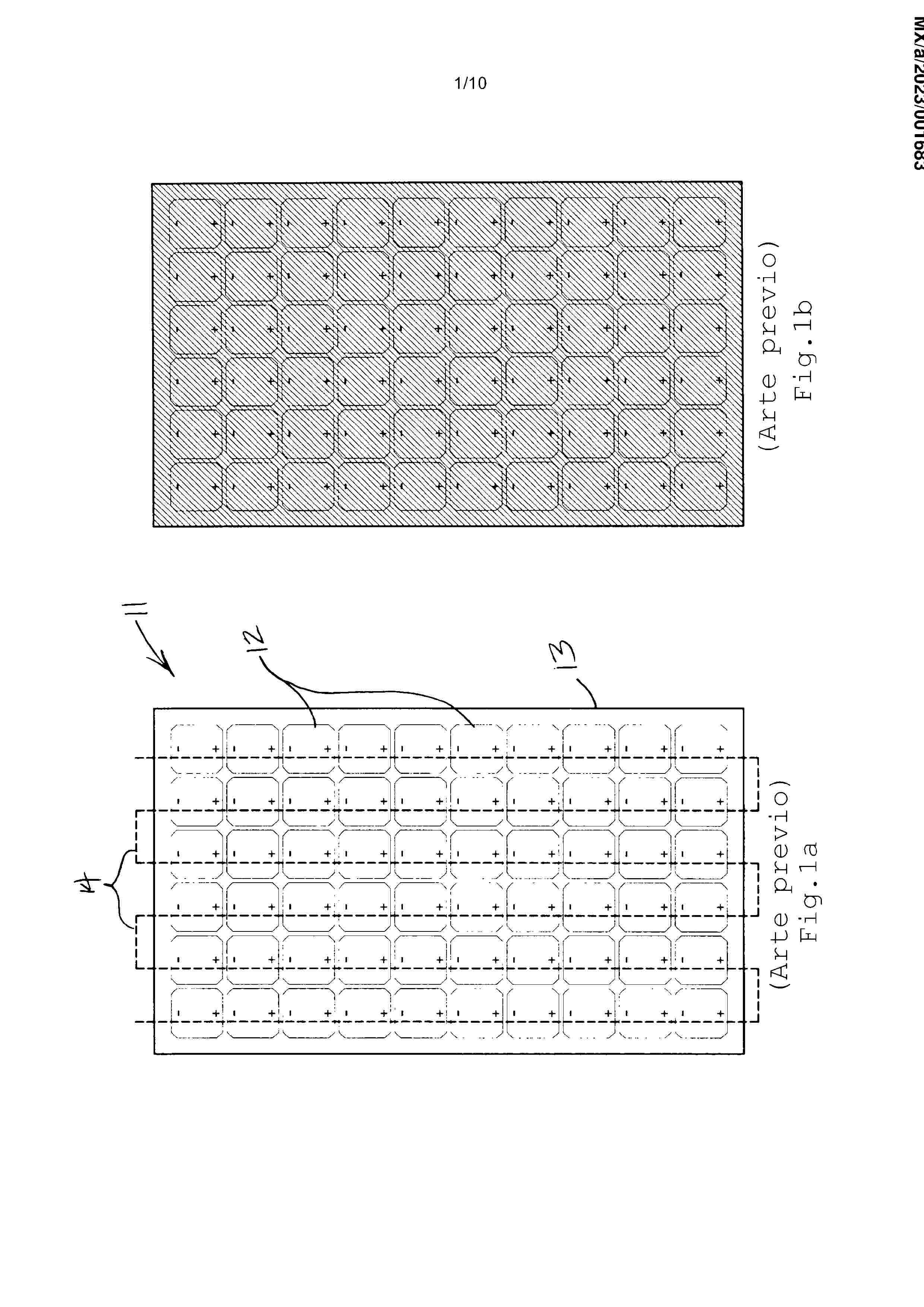
A photovoltaic module incorporates a lamination including a back-sheet, an array of solar cells supported on the back-sheet, and a transparent protective covering over the array of solar cells. The solar cells are arranged in offset or staggered patterns on the back-sheet to present a more random and less rigid industrial appearance to an observer. In some cases, cleaved solar cell segments are arranged into groups that are staggered on the back-sheet. This allows for finer control of the net voltage produced by a module. In other embodiments, full single wafer solar cells are arranged into larger groups, which themselves are staggered on the back-sheet. In either case, the result is a photovoltaic module with an appearance that is more organic and acceptable to homeowners and architects than traditional modules having cells arranged in rigid aligned rows and columns.
Resumen de: US2025244791A1
A finger-worn wearable ring device may include a ring-shaped housing, a printed circuit board, and a sensor module that includes one or more light-emitting components and one or more light-receiving components. The wearable ring device may further include a communication module configured to wirelessly communicate with an application executable on a user device.
Resumen de: US2025244792A1
A finger-worn wearable ring device may include a ring-shaped housing, a printed circuit board, and a sensor module that includes one or more light-emitting components and one or more light-receiving components. The wearable ring device may further include a communication module configured to wirelessly communicate with an application executable on a user device.
Resumen de: US2025248164A1
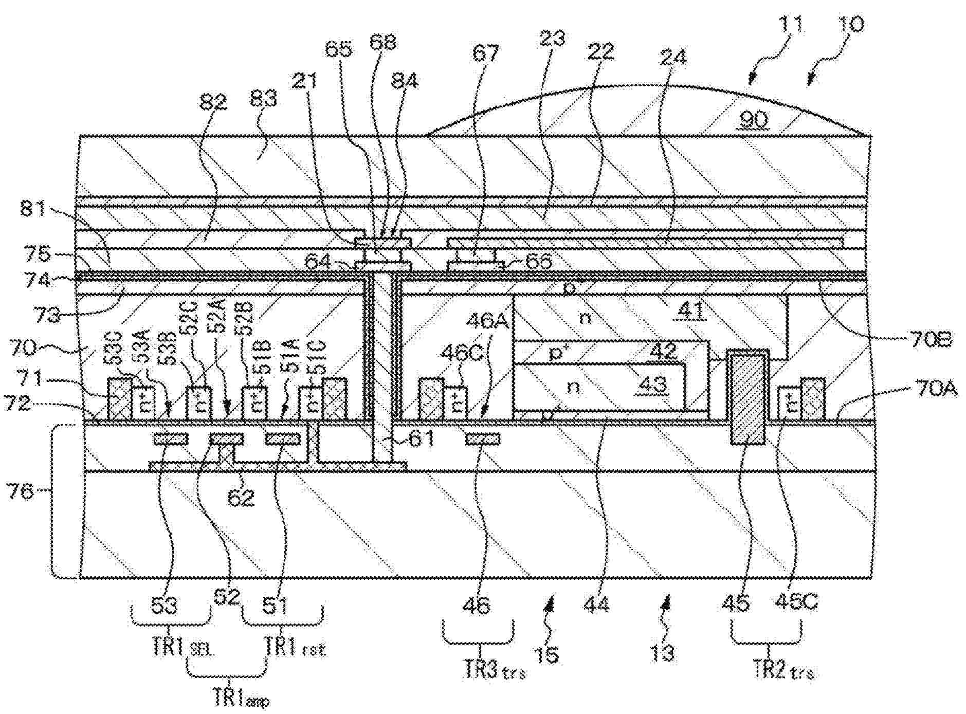
A solid-state image sensor includes a plurality of imaging element blocks 10 each configured from a plurality of imaging elements. Each of the imaging elements includes a first electrode, a charge accumulating electrode arranged in a spaced relation from the first electrode, a photoelectric conversion portion contacting with the first electrode and formed above the charge accumulating electrode with an insulating layer interposed therebetween, and a second electrode formed on the photoelectric conversion portion. The first electrode and the charge accumulating electrode are provided on an interlayer insulating layer, and the first electrode is connected to a connection portion provided in the interlayer insulating layer.
Resumen de: US2025244794A1
A finger-worn wearable ring device may include a ring-shaped housing, a printed circuit board, and a sensor module that includes one or more light-emitting components and one or more light-receiving components. The wearable ring device may further include a communication module configured to wirelessly communicate with an application executable on a user device.
Resumen de: US2025248230A1
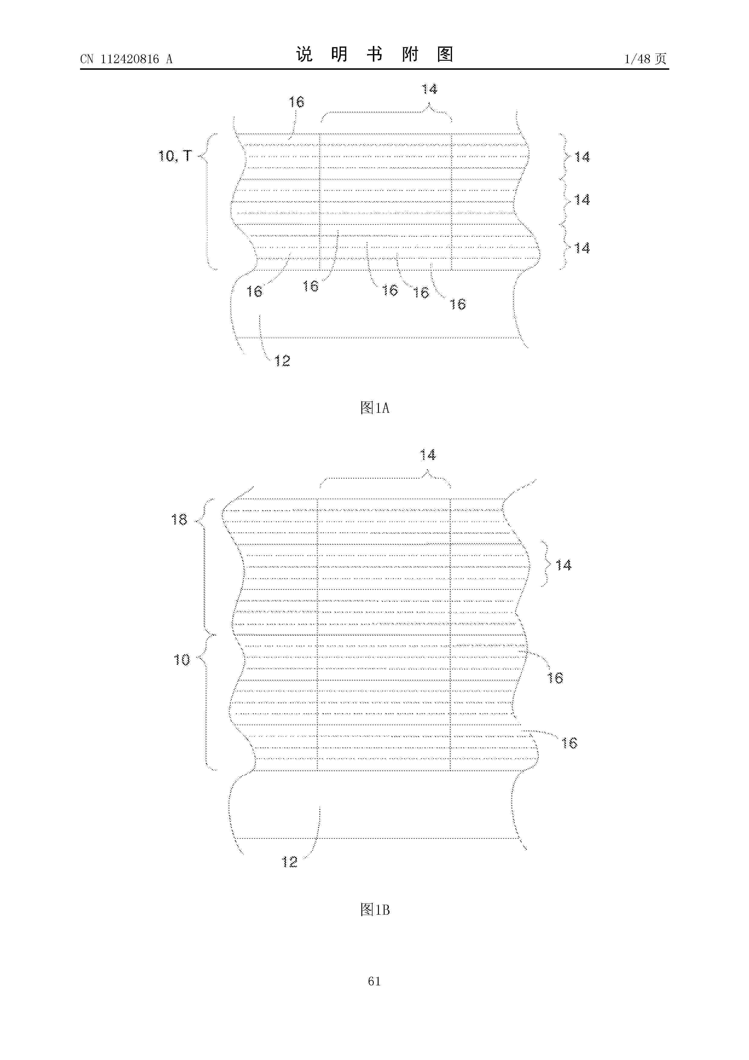
A display substrate includes a substrate, a planarization layer disposed on a side of the substrate, and a plurality of light-emitting layers disposed on a side of the planarization layer away from the substrate. The planarization layer includes a plurality of first portions and a second portion, a first portion is disposed in a sub-pixel region, and the second portion is located in a gap region between a plurality of sub-pixel regions; side surfaces of the plurality of first portions and side surfaces of the second portion have spacings therebetween to form a plurality of annular depressions, and an annular depression surrounds a first portion. A light-emitting layer covers the first portion of the planarization layer.
Resumen de: US2025248092A1
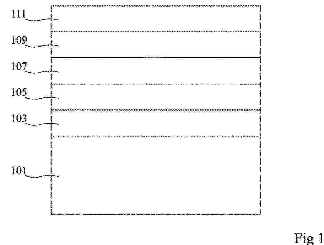
A superlattice cell that includes Group IV elements is repeated multiple times so as to form the superlattice. Each superlattice cell has multiple ordered atomic planes that are parallel to one another. At least two of the atomic planes in the superlattice cell have different chemical compositions. One or more of the atomic planes in the superlattice cell one or more components selected from the group consisting of carbon, tin, and lead. These superlattices make a variety of applications including, but not limited to, transistors, light sensors, and light sources.
Resumen de: US2025248263A1
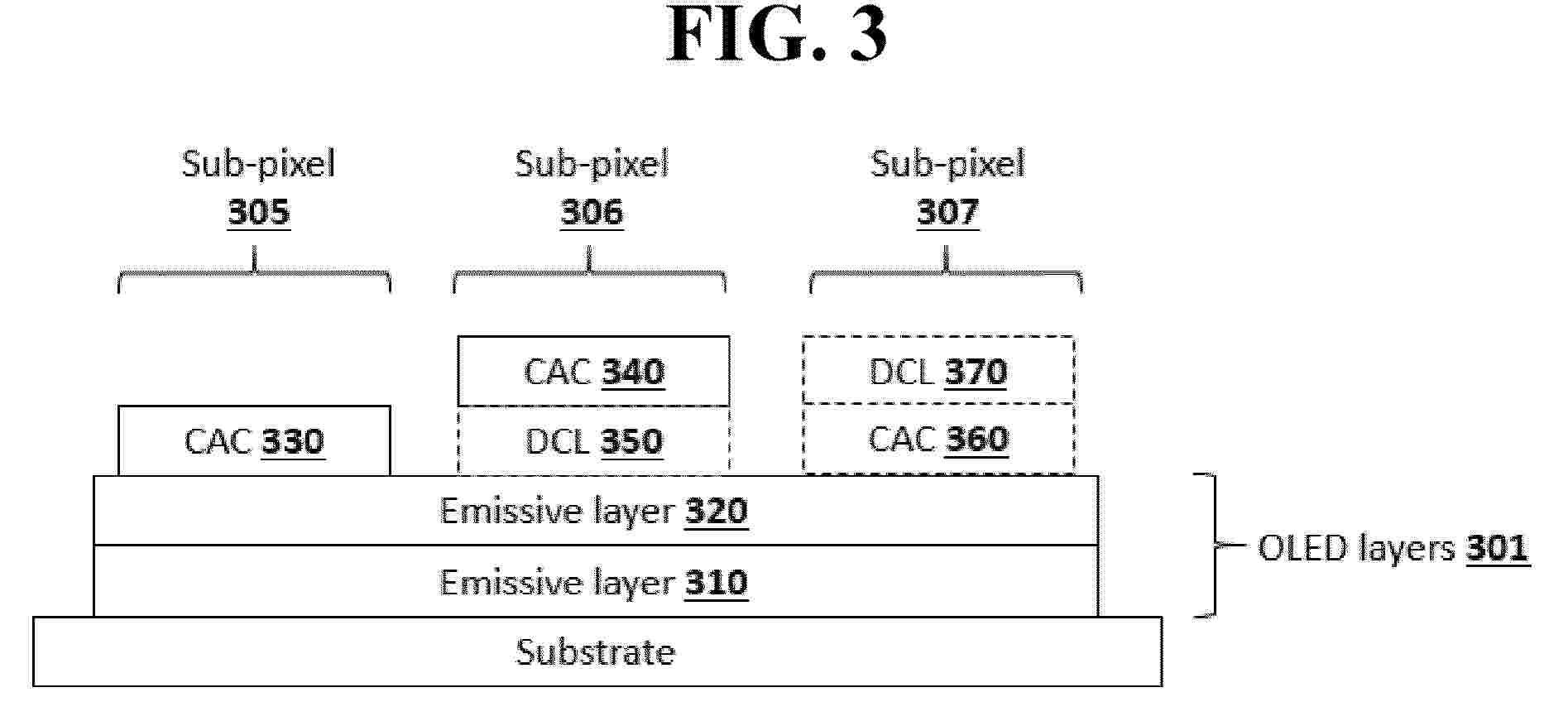
Full-color display arrangements and device architectures are provided that include a stack of unpatterned organic emissive layers, with color-altering layers and down-conversion layers to provide individual sub-pixels, where the emissive stack includes not more than two distinct emissive colors.
Resumen de: US2025248169A1
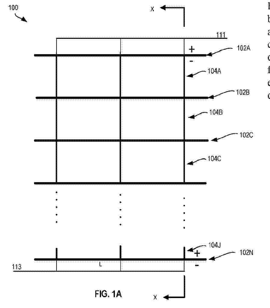
A solar cell is provided, including: a substrate including a center region and edge regions respectively arranged on two opposing sides of the center region, fingers arranged at intervals along the first direction and extending along a second direction, pad groups arranged at intervals along the second direction, and busbars arranged at intervals along the second direction. The fingers including a number of fingers in the center region, each pad group includes pads arranged at intervals along the first direction, and the pads include a number of pads in the center region that are respectively connected to the number of fingers in the center region. Each busbar is connected to a respective pad group of some of the pad groups, and at least one pad group is disposed between two adjacent busbars.
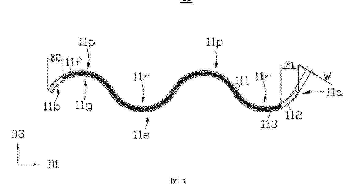
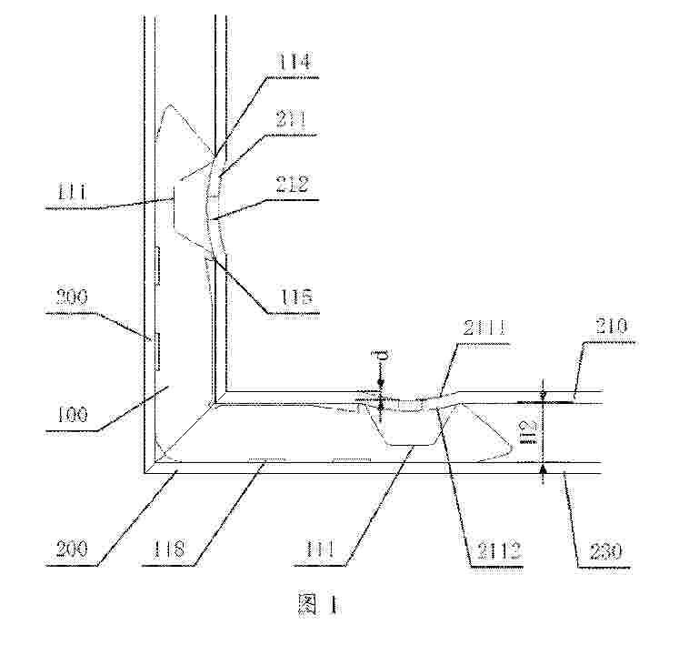
Resumen de: US2025247043A1
The invention relates to a photoelectric building block comprising a rigid support (1), made of a single extruded piece of non-metal material, provided with a front with a first coupling configuration (10) formed by a sunken channel (11) between two opposing parallel grooved guides (12) that define a narrowing of the opening of the sunken channel (11), at least one photoelectric panel (2) with a second coupling configuration (20) inserted into the sunken channel (11) and having opposite coupling ends (21) inserted into the two grooved guides (12); wherein the photoelectric building block further comprises a retainer device (30) which exerts a thrust on the opposite coupling ends (21) of the second coupling configuration (20), moving them away from the bottom of said sunken channel (11) and thrusting them against the lower surface (13) of the two grooved guides (12), retaining the photoelectric panel (2).
Resumen de: US2025247048A1
A hybrid photovoltaic thermal (PVT) system including flexible integration of spectral splitting optical filtration and thermal management utilities is described. An optical filtration (OF) channel is provided above a PV panel of the hybrid PVT system, wherein an OF fluid in the OF channel transmits a first light that is within a predefined spectral range and absorbs a second light that is outside the predefined spectral range. A cooling fluid (CF) channel is provided below the PV panel, wherein the CF channel contains a cooling fluid. A phase change material (PCM) layer is provided between the PV panel and the CF channel, wherein at least one of the OF fluid in the OF channel, the cooling fluid in the CF channel, or the PCM layer contains nanoparticles.
Resumen de: US2025247045A1
Variable angle torque tube connectors are described that include a means for connecting different torque tube sections at different angular orientations. The means for connecting may also translate rotation from one torque tube section to another. In some embodiments, the variable angle torque tube connector may also include a means for applying a rotational torque to a component of the means for connecting different torque tube sections in order to rotate the torque tube sections so that attached photovoltaic modules track a location of the Sun throughout the day.
Resumen de: US2025247046A1
A solar module frame coupling assembly includes a solar module frame and a rail. The solar module frame includes a frame side portion having a protruded guide structure. The rail includes a first rail side and a second rail side that is opposite the first rail side. The first rail side is configured to interface with a torque tube, and the second rail side includes an alignment slot. The alignment slot is configured to receive the protruded guide structure to couple the solar module frame to the rail.
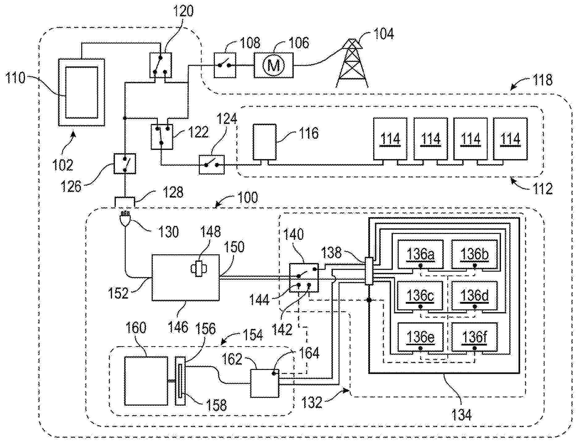
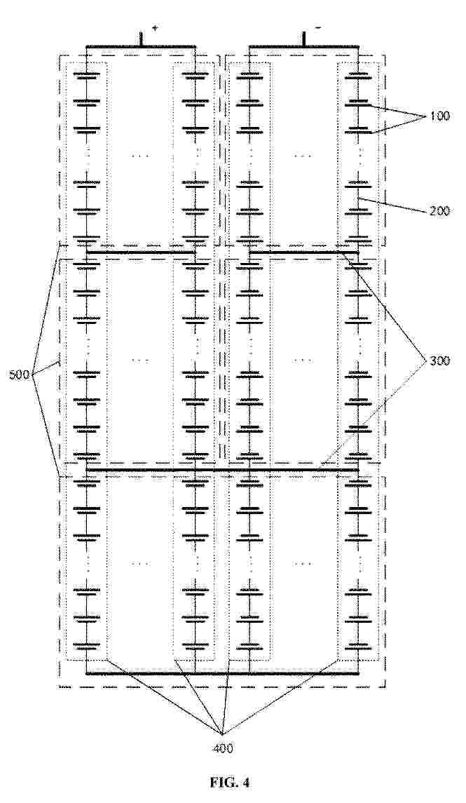
Resumen de: US2025247047A1
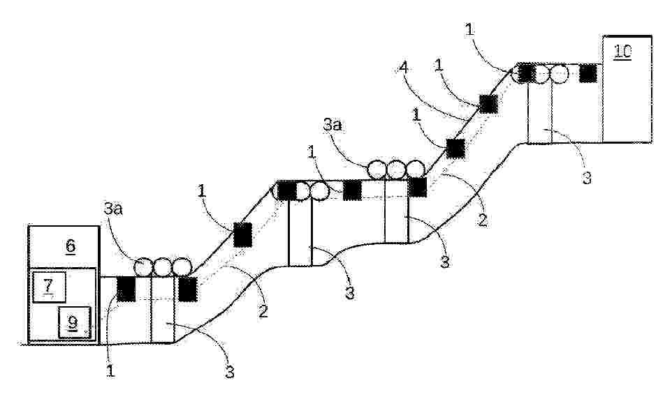
An electric generator comprises solar modules, a station and an additional station connected by a hauling cable supporting the solar modules and a hauling cable moving the solar modules. Each solar module is attached to the hauling cable by a detachable connector. A station is provided with means for moving the hauling cable to move the solar modules along the loop with respect to the station. A control circuit is configured to move the solar modules from a production position to a rest position by moving the hauling cable.
Resumen de: US2025247044A1
A solar racking system, which is capable of adjusting the angle of solar panels for solar tracking. The solar racking system comprises a pier, a movable frame, a positioning seat, and a linear actuator. The movable frame is pivotally mounted on the pier with a crossbar as an axis, and the positioning seat is fixed to the crossbar at a first end of the positioning seat. One end of the linear actuator is attached to the pier and the other end of the linear actuator is attached to a second end of the positioning seat. When the linear actuator is operated, the movable frame pivots relative to the pier. The design of the solar racking system is simple, stable, and allows for angle adjustments of the solar panels to enhance energy conversion efficiency.
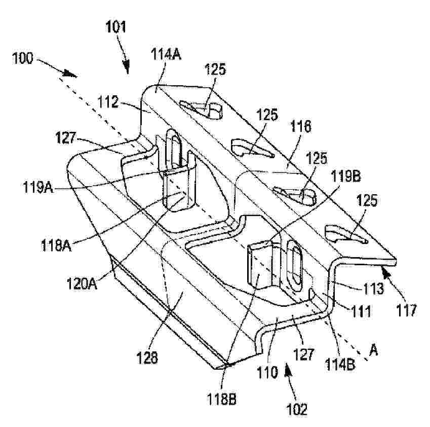
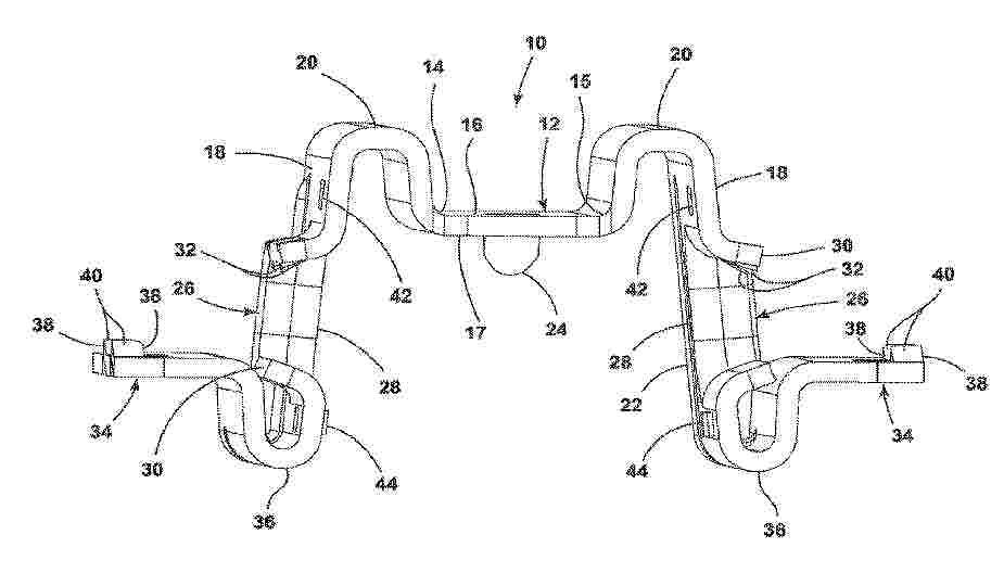
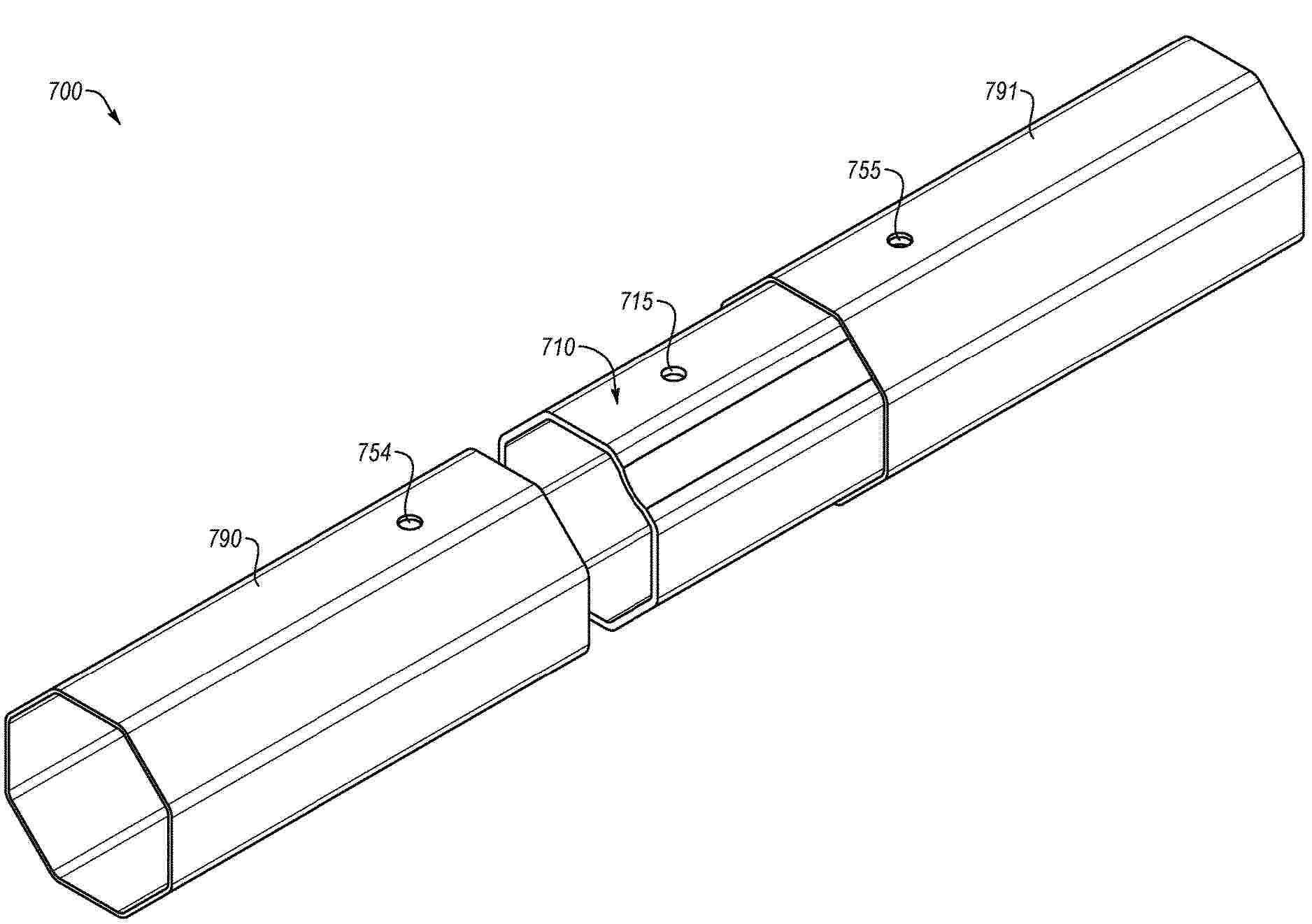
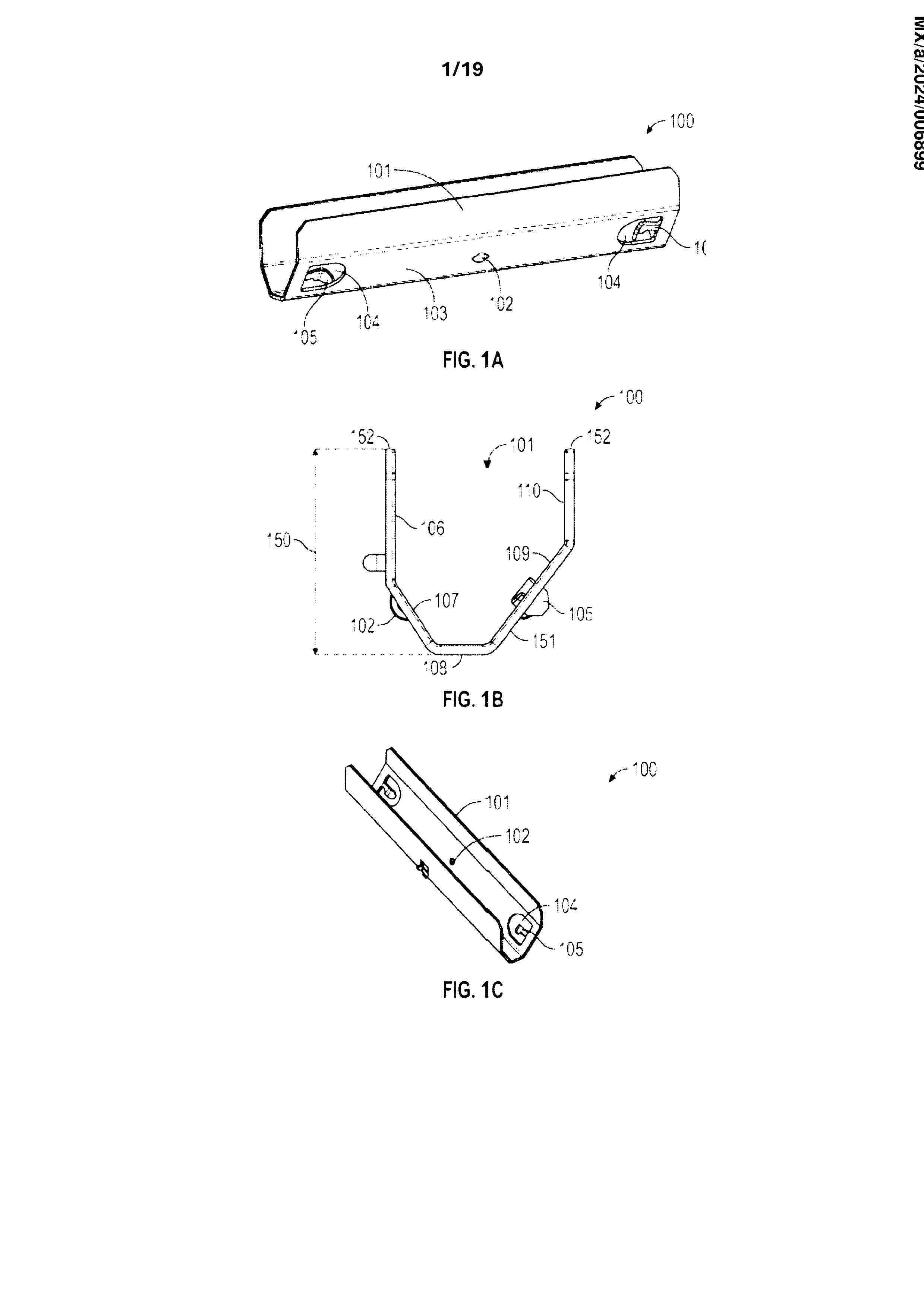
Resumen de: US2025247040A1
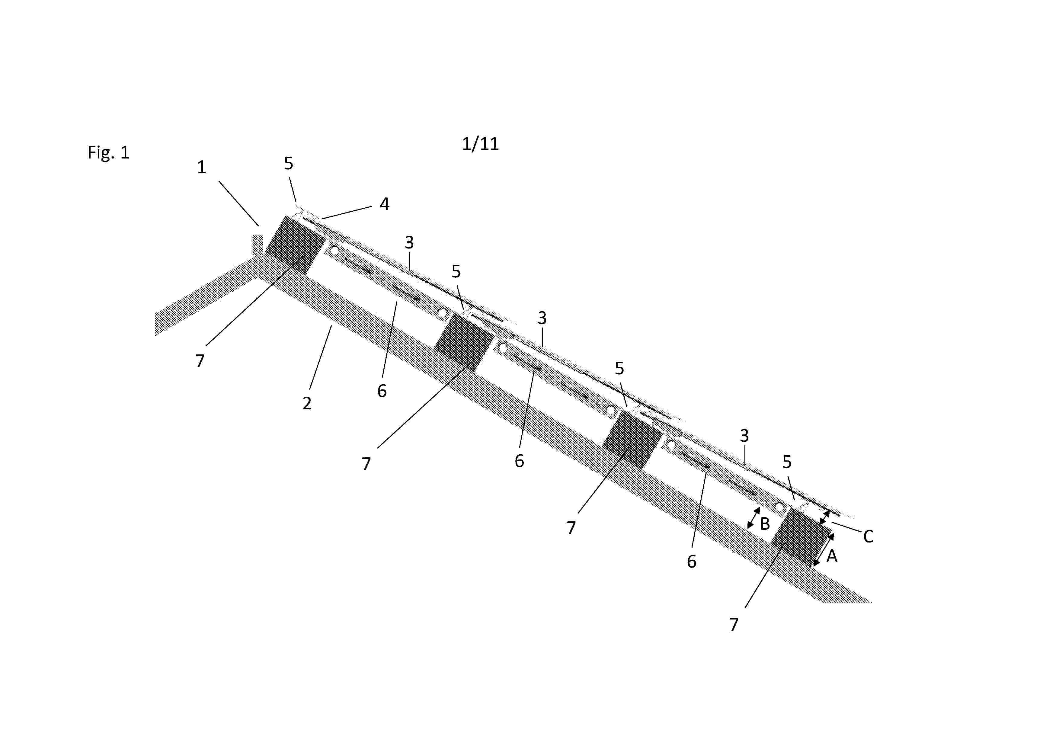
A holding part includes: a main part that extends along an elongation axis A and comprises a first side wall, the first side wall having a first inner face and a first outer face as well as a first upper edge parallel to the elongation axis A. The main portion has two transverse walls that are perpendicular to the elongation axis and define a passage open at the rear face for the insertion of a clamping element of the fastening kit. The transverse walls have a holding edge defining a holding plane and against which the clamping element is intended to exert force. The holding part also includes a first lateral wing extending the main portion laterally and intended to bear against a useful face of the panel opposite the contact face.
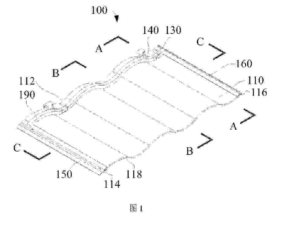
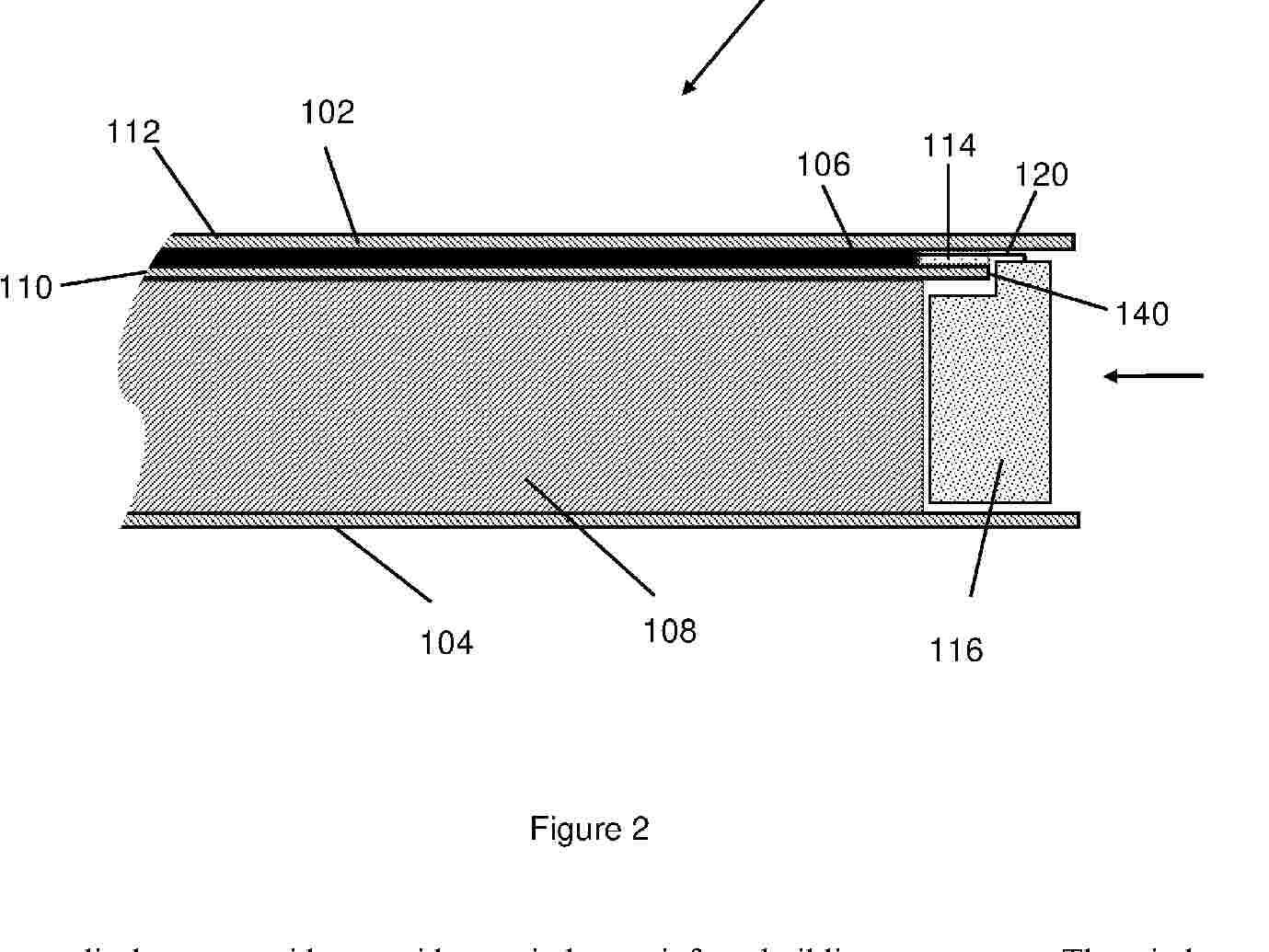
Resumen de: US2025247042A1
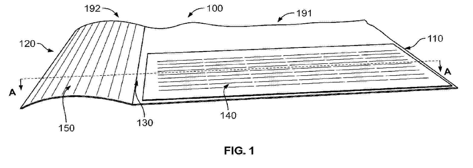
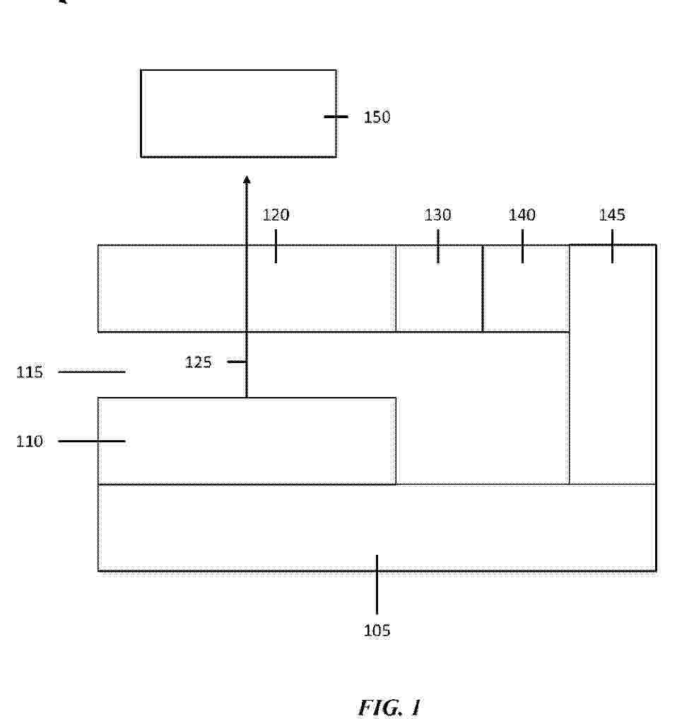
A building integrated photovoltaic (BIPV) system. The BIPV system includes a plurality of photovoltaic elements. A cable couples the plurality of photovoltaic elements to an energy storage. A plurality of cladding backplates secure the plurality of photovoltaic elements to a building envelope. Each of the cladding backplates including an upper ridge and a lower ridge to secure the photovoltaic element therebetween. A connection tab is positioned on a lateral side of the cladding backplate.
Resumen de: WO2024062187A1
The present invention relates to a photovoltaic module comprising, inter alia, a lower electrode consisting of two layers: a first layer (210A) comprising a polymer blend of poly(3,4-ethylenedioxythiophene) and sodium poly(styrene sulfonate) covering the support and having an average thickness of between 50 nm and 150 nm and an organic fibrous structure, and a second layer (210B) based on an organic polymer or molecule covering said first layer, the lower electrode having a lower surface in contact with the support and an upper surface, and an upper electrode (212) comprising a polymer blend of poly(3,4-ethylenedioxythiophene) and sodium poly(styrene sulfonate) covering said photovoltaic active layer (211), said electrode being continuous and having an average thickness of between 100 nm and 400 nm and an organic fibrous structure.
Resumen de: EP4593273A1
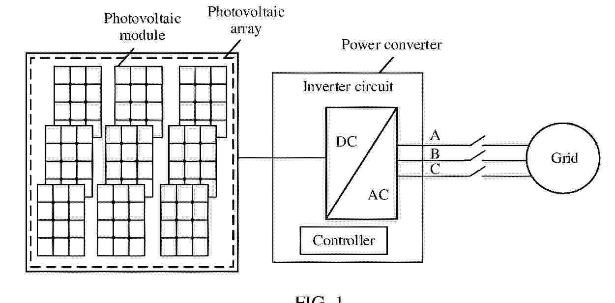
This application provides a power converter and a power converter control method. The power converter includes a three-phase inverter circuit and a controller. The controller is configured to: when a value of a maximum phase voltage in three-phase voltages output by the three-phase inverter circuit is greater than a first voltage value, a value of a minimum phase voltage in the three-phase voltages output by the three-phase inverter circuit is less than a second voltage value, and a positive-sequence component of the three-phase voltages is greater than a third voltage value, or when an absolute value of a difference between any phase voltage and another phase voltage in three-phase voltages is greater than a first preset threshold, and a positive-sequence component of the three-phase voltages is greater than a third voltage value, control an active current and a reactive current that are output by the three-phase inverter circuit to be a first current value and a second current value respectively, where the first current value and the second current value are fixed values. According to this application, the power converter can support switching of a power supply system from phase-loss on-grid to normal on-grid without disconnecting from a grid.
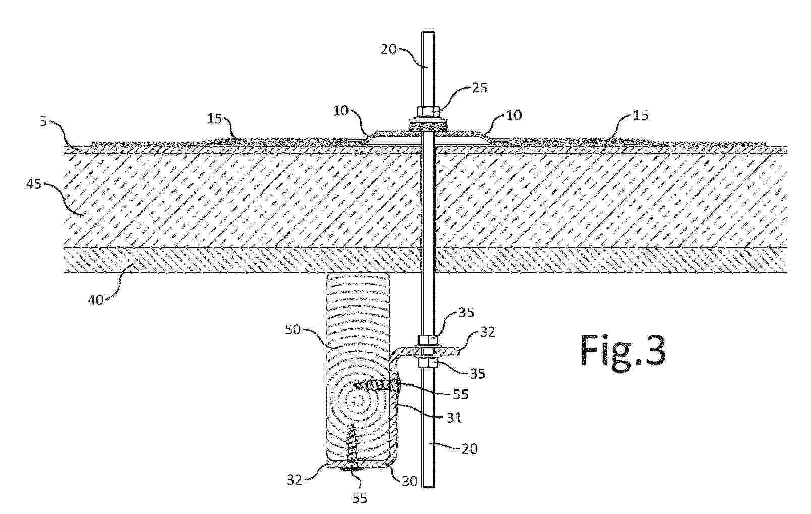
Resumen de: EP4592469A1
A mounting device for an upstand on a roof surface (5), which roof surface (5) is supported by a beam construction (50), comprises a mounting base (10, 15) to be fastened to the roof surface. The mounting base (10, 15) provides fastening means (20) for mounting of the upstand. The mounting device comprises an adapter device (30) which is intended and configured for a durable and firm connection to a beam (50) of the beam construction. To the side of the beam (50) a force transmission is provided between the adapter device (30) and the fastening means (20).
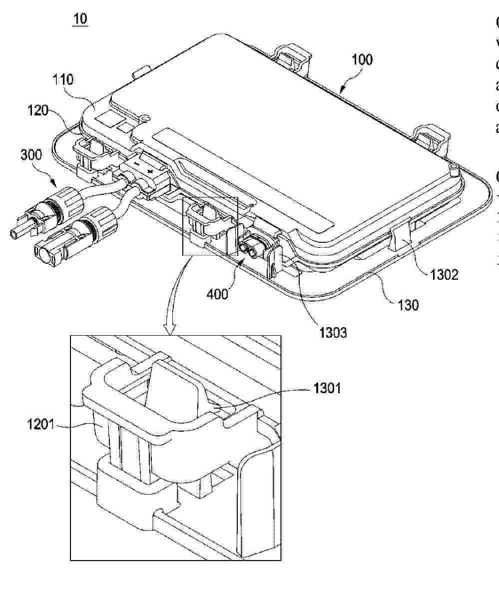
Resumen de: CN119948300A
A clamp for securing a photovoltaic panel to a securing device is provided. The clamp (10) includes a central portion (12) having a pair of opposing transverse ends (14, 15) and opposing front and rear longitudinal ends (16, 17). A pair of side walls (18) extend from the lateral ends (14, 15) of the central portion (12). A longitudinally extending jaw (26) is formed in each of the side walls (18). Each jaw (26) defines a C-shaped groove (28). An end portion (34) extends outwardly from each of the sidewalls (18). At least one engagement member (38) extends from each of the end portions (34). The central portion (12) and the side walls (18) together have an open cross-section, and the clamp (10) is compressible and expandable in a transverse direction.
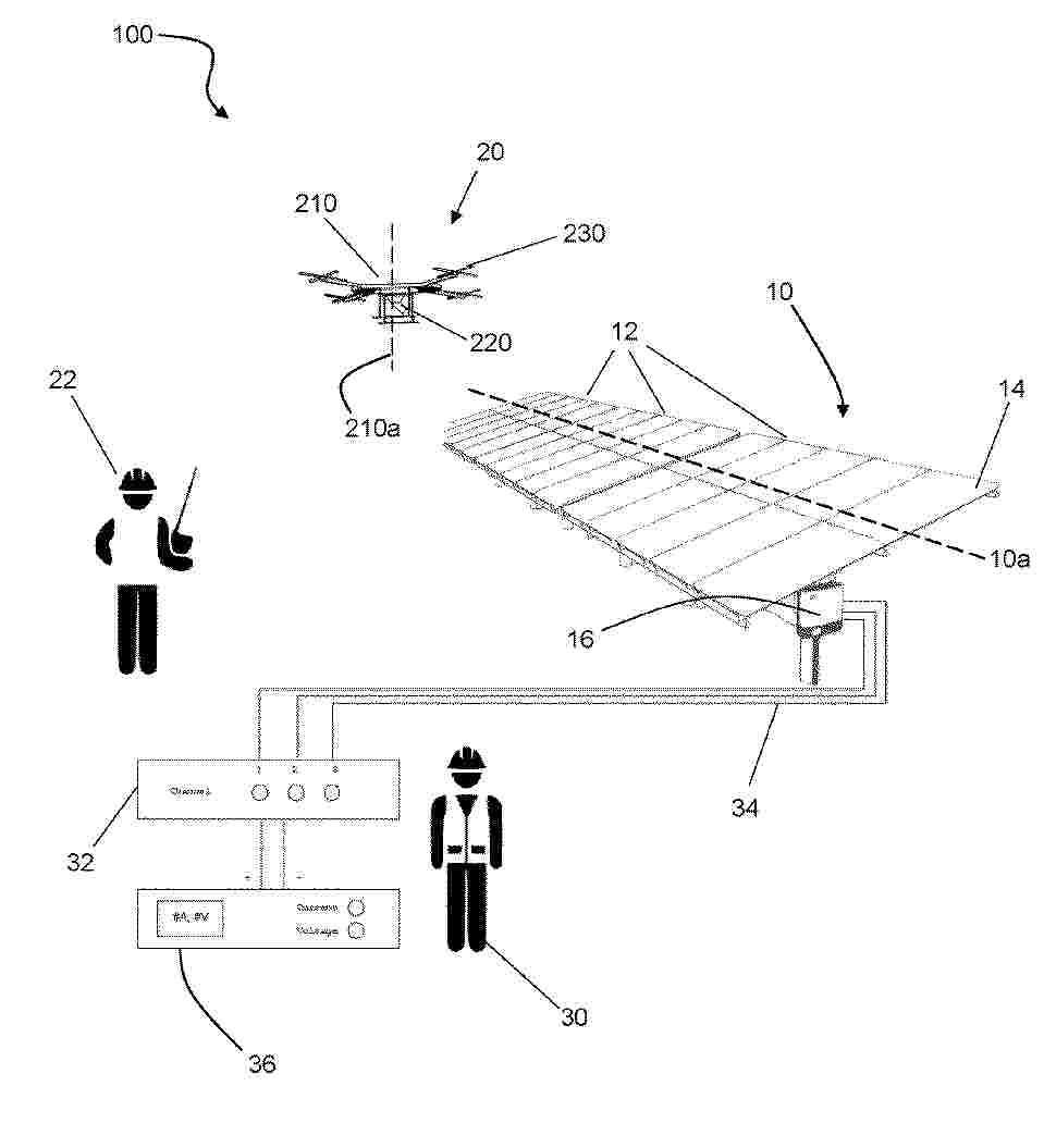
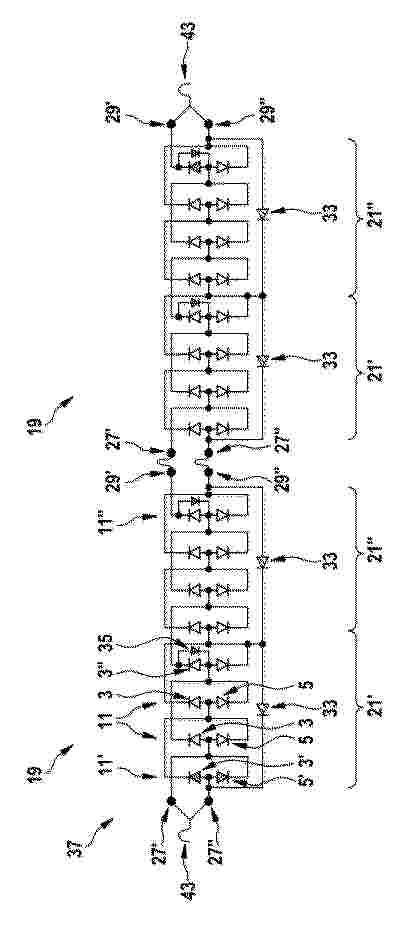
Resumen de: EP4592640A2
A method of controlling movement of an aerial vehicle having a camera for capturing EL images of a PV array, the method comprising: controlling the aerial vehicle to fly along a flight path to capture EL images of corresponding PV array subsections of the PV array; deriving respective image quality parameters from at least some of the captured EL images, wherein the image quality parameters include a SNR scanning factor and a motion blur scanning factor; and dynamically adjusting a flight speed of the aerial vehicle along the flight path, based on the respective image quality parameters for capturing the EL images of the PV array subsections by: deriving a target flight speed based on a minimum of the SNR scanning factor and the motion blur scanning factor; and dynamically adjusting the current flight speed of the aerial vehicle to match the target flight speed.
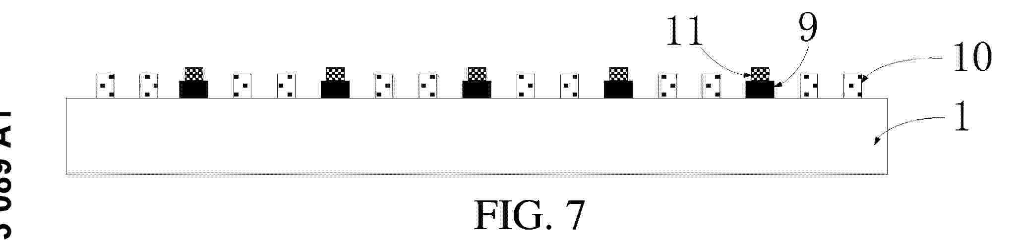
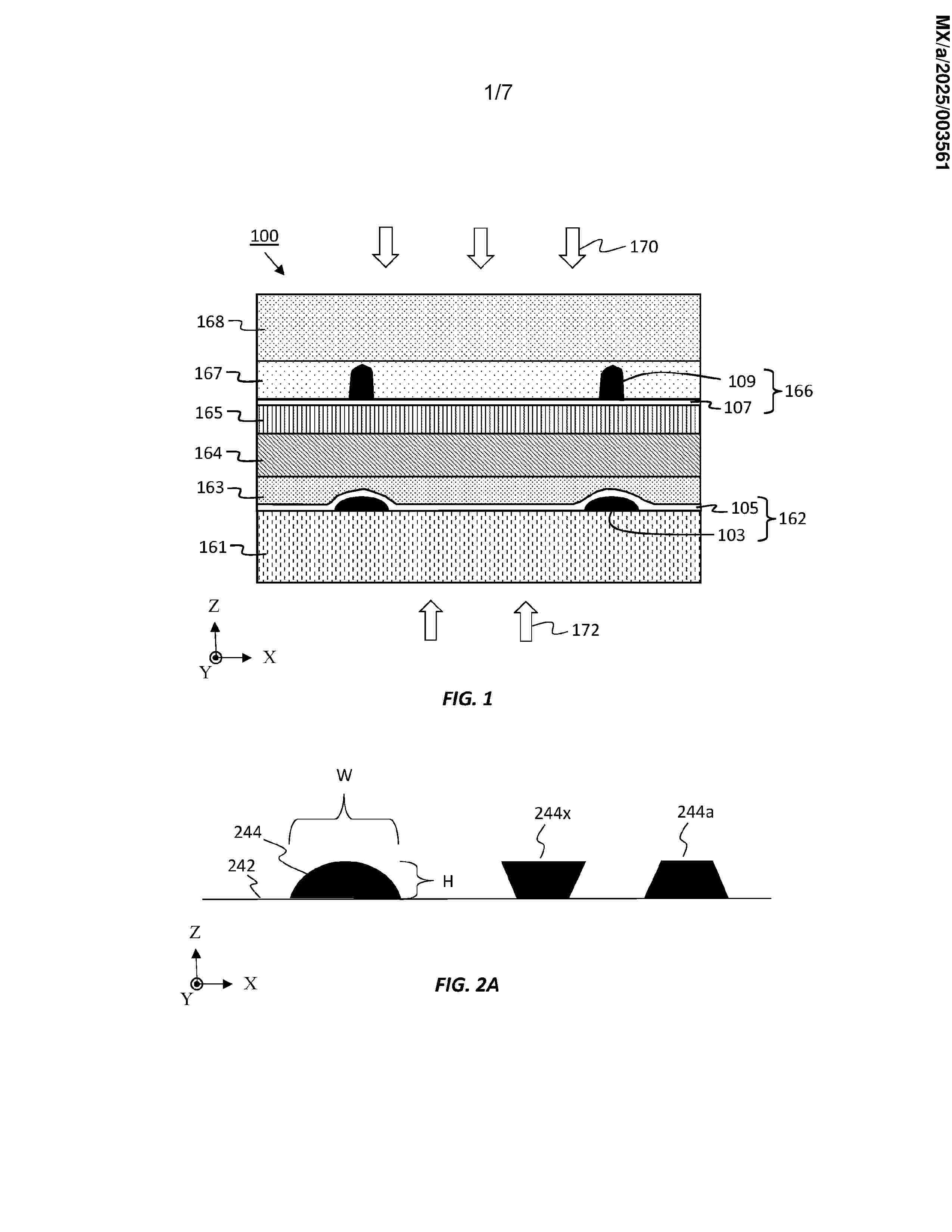
Resumen de: EP4593089A1
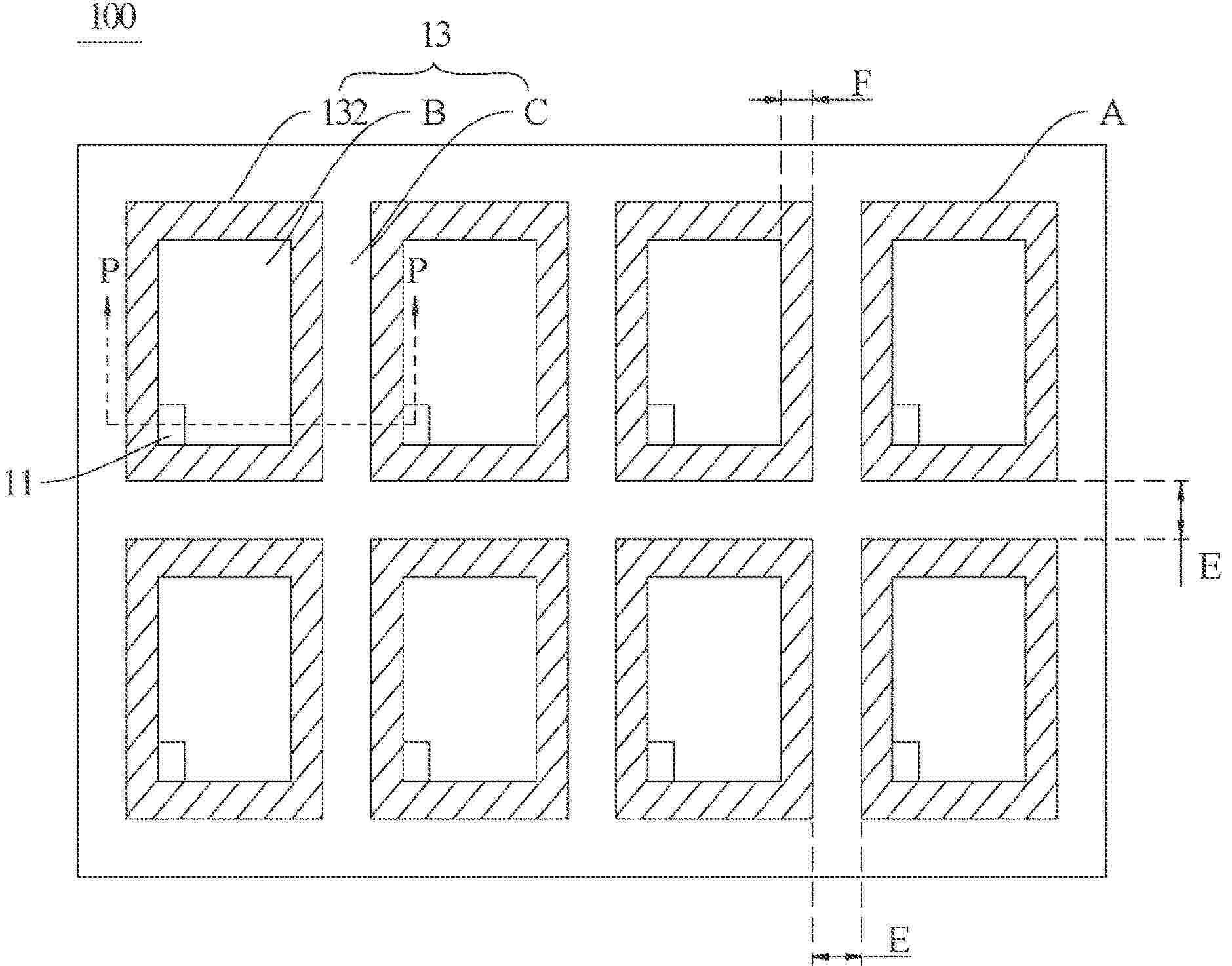
This application discloses a photovoltaic solar cell, a manufacturing method thereof, and a photovoltaic module, . The photovoltaic solar cell structure includes: a back contact solar cell, a soldering portion, an insulating material, and a conductive material. Each of the soldering portion is at least located on a corresponding busbar included in the back contact solar cell. The insulating material covers at least a target part of each finger included in the back contact solar cell. The target part is a part in which a distance between each of the finger and a busbar having a polarity opposite to that of the finger is less than a preset distance. The conductive material is formed on each of the soldering portion, and a height of a top of the conductive material is greater than or equal to a height of a top of the insulating material.
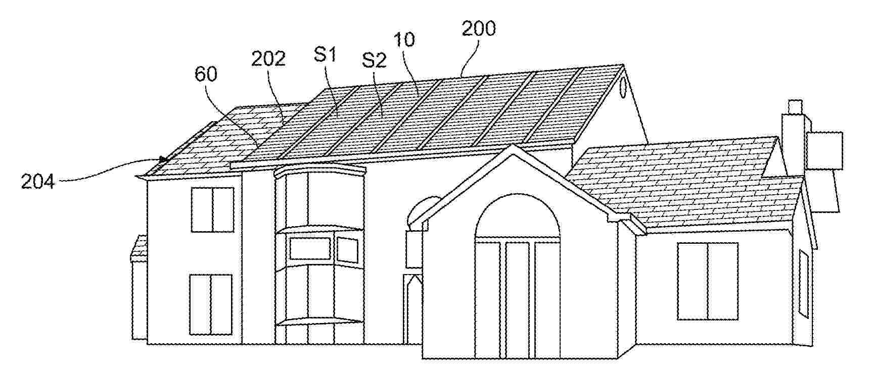
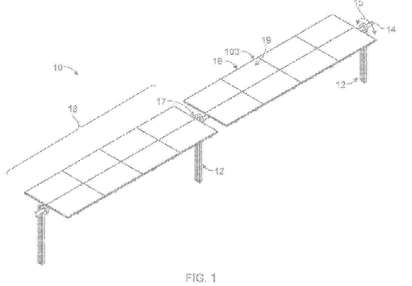
Resumen de: US2025150021A1
A system includes first, second and third photovoltaic modules on a rood. Each module includes an upper edge, a lower edge and at least one solar cell. Lower edges of the cells of the first and second modules are offset from lower edges of the first and second modules. Upper edge of the cell of the second module is offset from the upper edge of the second module. The upper edge of the cell of the third module is offset from the upper edge of the third module. The first module overlays the second module. The lower edge of the cell of the first module is substantially aligned with the upper edge of the cell of the second module. The second module overlays the third module. The lower edge of the cell of the second module is substantially aligned with the upper edge of the cell of the third module.
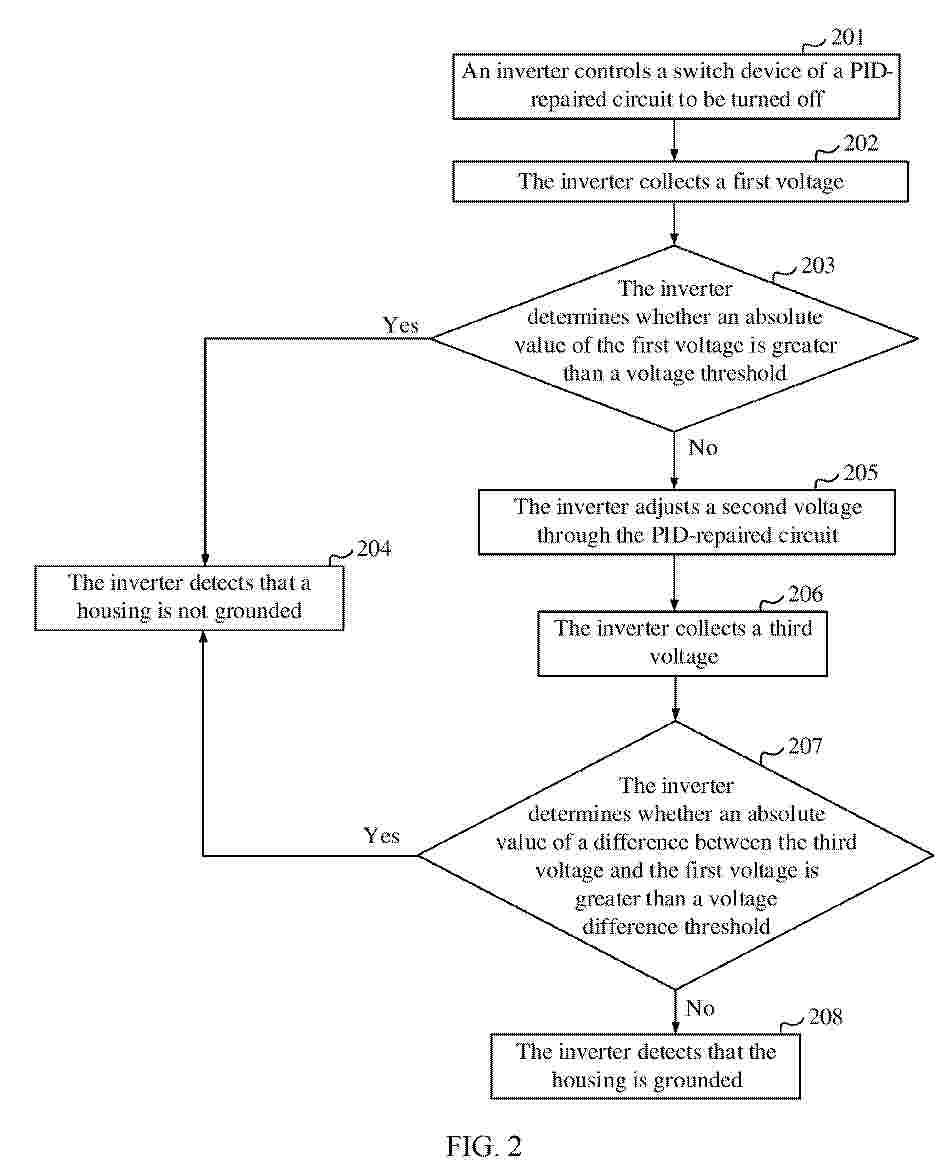
Resumen de: EP4592699A1
The present invention discloses a housing grounding detection method and an inverter. The inverter includes a bus positive electrode, a bus negative electrode, a ground wire end, a PID-repaired circuit, a first detection resistor, a second detection resistor, and a housing. The first detection resistor is connected to the bus positive electrode and the housing. The second detection resistor is connected to the bus negative electrode and the housing. The repaired circuit is connected to the bus negative electrode and the housing. The inverter is connected to a power generation module. The method includes: collecting a first voltage, that is, a voltage between the housing and the ground wire end; when an absolute value of the first voltage is not greater than a voltage threshold, adjusting a second voltage through the repaired circuit, where the second voltage is a voltage between the bus negative electrode and the ground wire end; and collecting a third voltage, that is, a voltage between the housing and the ground wire end after the second voltage is adjusted, where an absolute value of a difference between the third voltage and the first voltage is not greater than a voltage difference threshold, to detect whether the housing is grounded. According to the present invention, whether the housing is grounded is determined based on a change of a voltage of the housing to the ground, and no additional detection component is added. This improves system safety.
Resumen de: US2024305078A1
A wire clamp may include a bottom piece having: a first base portion defining a first aperture, an at least partially elliptical barrier extending from the first base portion about the first aperture, and a plurality of legs extending from sides of the first base portion; a top piece having: a second base portion, a protrusion extending from the second base portion, the protrusion defining a second aperture, and a plurality of legs extending from sides of the second base portion; and a fastener. The first aperture and the second aperture may be configured to align and receive the fastener therethrough. A first side of the partially elliptical barrier and a first portion of the plurality of legs may define a first wire channel, and a second side of the partially elliptical barrier and a second portion of the plurality of legs may define a second wire channel.
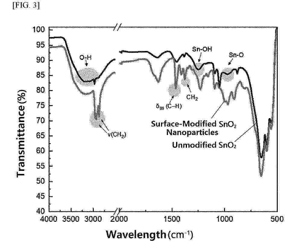
Resumen de: EP4593564A1
The present invention relates to a coating agent for forming an electron transport layer (or electron transfer layer), wherein surface-modified metal oxide nanoparticles prepared in the form of a dispersion solution are provided as the coating agent, and relates to an inverted perovskite in which an electron transport layer is formed using the same.
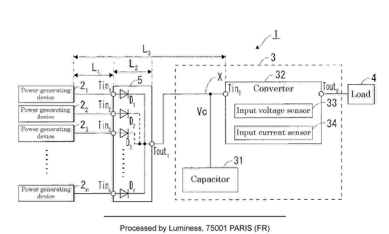
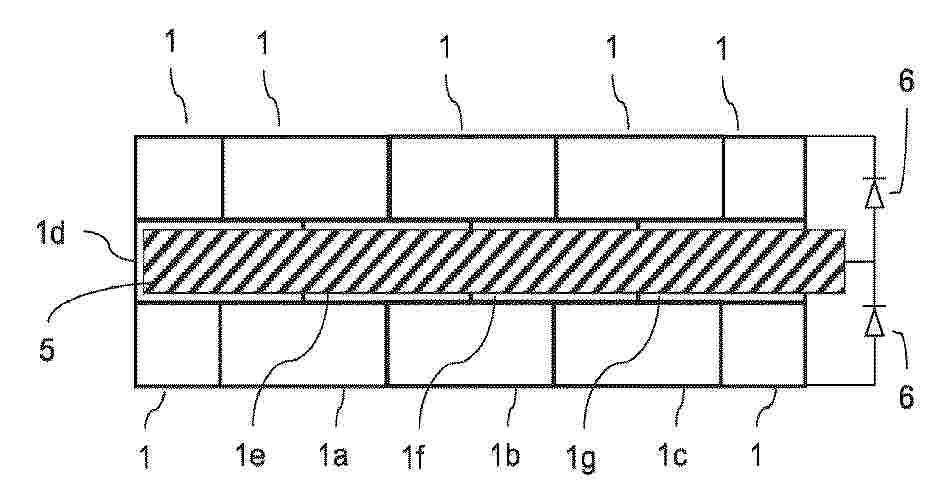
Resumen de: EP4593231A1
A power generating system (1) includes: power generating devices (2<sub>1</sub> to 2<sub>n</sub>); a junction box (5) including a plurality of diodes (D<sub>1</sub> to D<sub>n</sub>) each configured to prevent backflow to a corresponding one of the power generating devices (2<sub>1</sub> to 2<sub>n</sub>); a converter (32) configured to convert power generated by the power generating devices (2<sub>1</sub> to 2<sub>n</sub>) into power suitable for a load; and a capacitor (31) connected to a common wiring line connecting the junction box (5) and the converter (32). The converter (32) is configured to perform constant voltage control so that a capacitor voltage (Vc) of the capacitor (31) becomes a voltage command value (VA) that is preset.
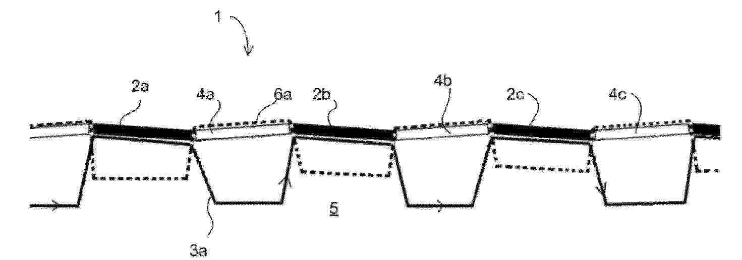
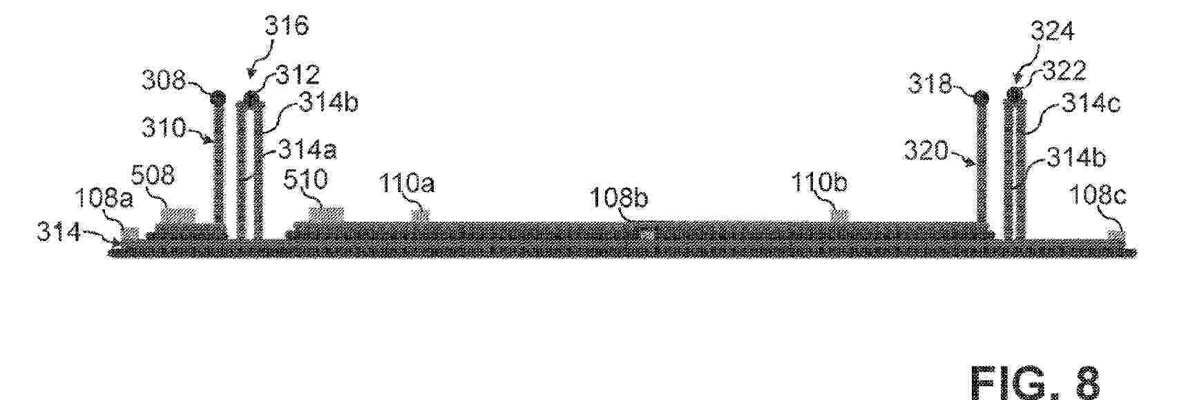
Resumen de: WO2024062158A1
A solar panel system (1) comprising solar panels (2a, 2b, 2c) arranged in the ground (5) on the ground surface, and thermal insulation materials (4a, 4b, 4c) arranged to at least some of the interspaces between the solar panels (2a, 2b, 2c) in the ground (5) on the ground surface, so that solar panels and thermal insulation materials alternate in the solar panels system. Furthermore, the solar panel system comprises a cooling pipework arranged so that the cooling pipework comprises pipes (3a) arranged close to the ground surface at the point of location of the solar panels or mounted to the surface of the solar panel facing the ground surface, and at the point of location of the thermal insulation material the pipes (3a) are arranged substantially deeper in the ground.
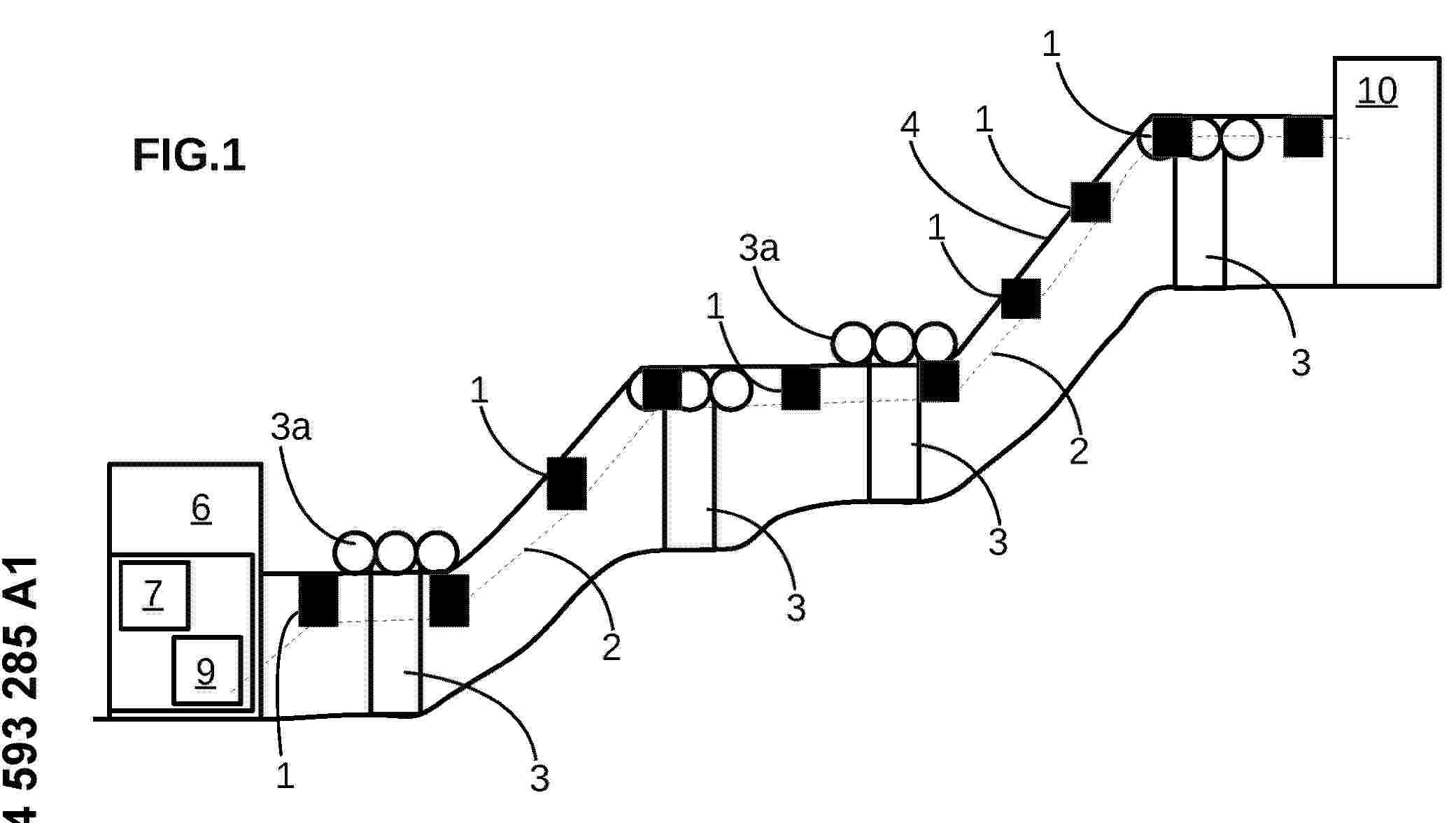
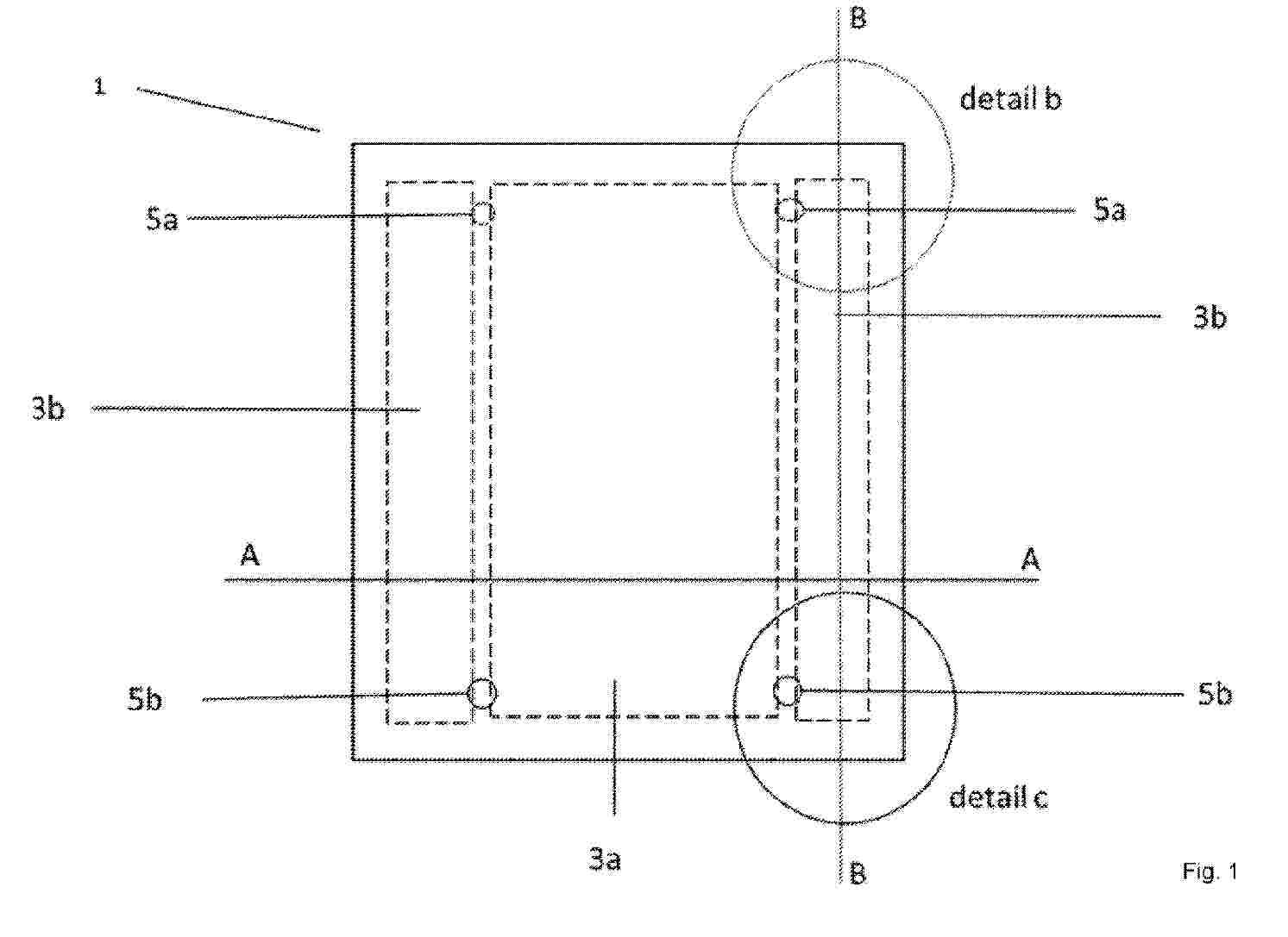
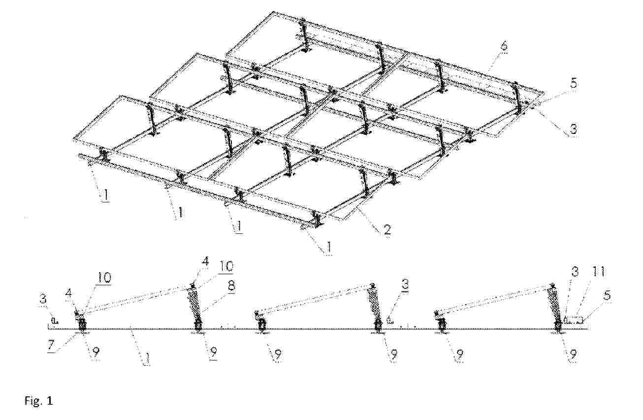
Resumen de: EP4593285A1
Un générateur électrique comporte des modules photovoltaïques (1), une station (6) et une station additionnelle (10) reliées par un câble porteur (4a) supportant les modules photovoltaïques (1) et un câble tracteur (4b) déplaçant les modules photovoltaïques (1). Chaque module photovoltaïque (1) est fixé au câble tracteur (4b) par un connecteur (5) débrayable. Une station (6) est munie de moyens de déplacement du câble tracteur (4b) pour déplacer les modules photovoltaïques (1) le long de la boucle par rapport à la station (6). Un circuit de commande (9) est configuré pour déplacer les modules photovoltaïques (1) d'une position de production à une position de repos en déplaçant le câble tracteur (4b).
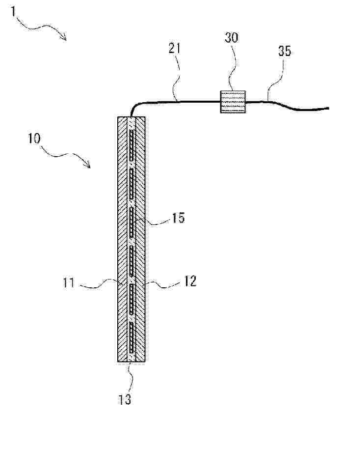
Resumen de: WO2024062186A1
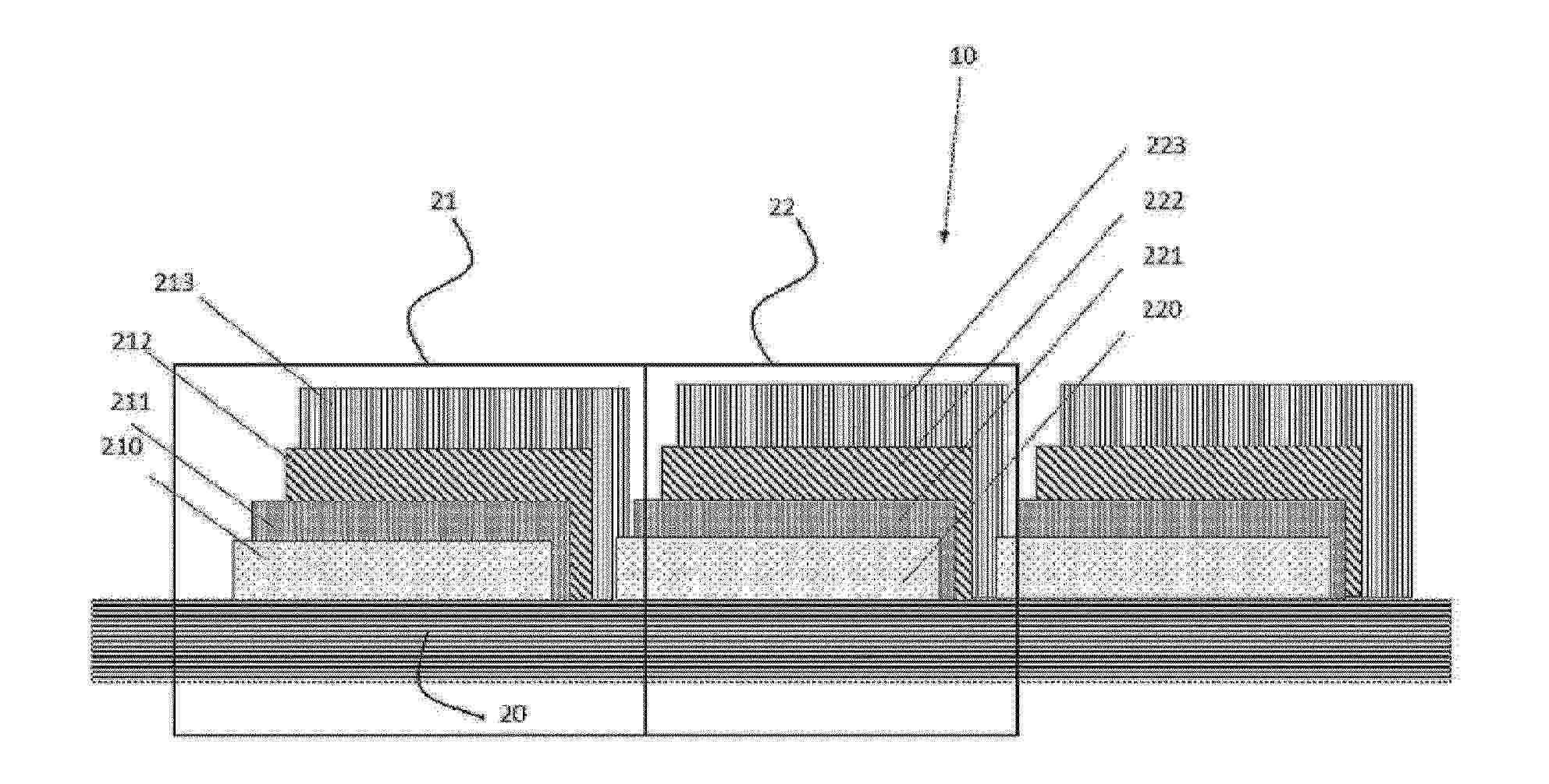
The invention relates to photovoltaic modules, and in particular to photovoltaic modules comprising a plurality of organic photovoltaic cells (21, 22) (usually referred to as OPC or Organic Photovoltaic Cells).
Resumen de: WO2024062451A1
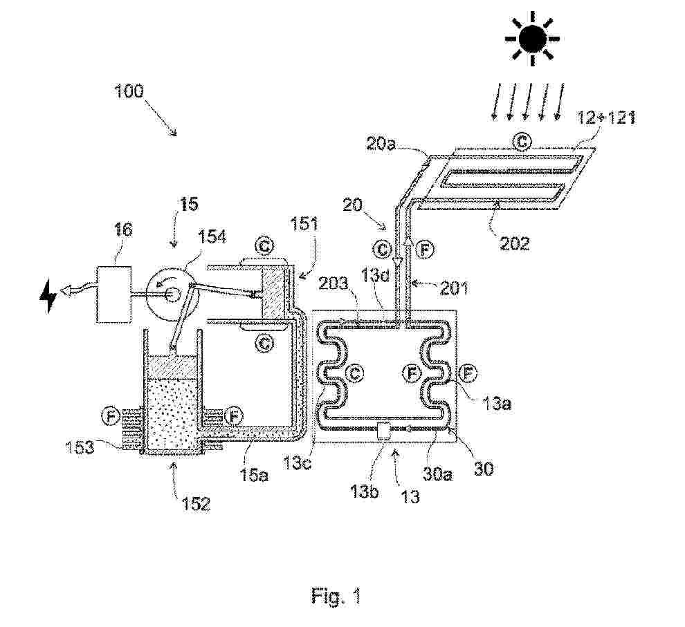
The invention concerns a hybrid solar power generation system (100) comprising: - a set of photovoltaic panels (12), - a first loop circuit (20) containing a heat-carrying fluid (20a) able to circulate along the first loop circuit (20), said first loop circuit (20) defining a first portion (201) for circulation of the fluid in a first temperature range, a second portion (202) adjacent to said photovoltaic panels (12) for thermal exchange between the fluid (20a) and said photovoltaic panels (12) and a third portion (203) for circulation of the fluid in a second temperature range, wherein the temperatures of the second temperature range are greater than the temperatures of the first temperature range, - a heat pump (13) with a second loop circuit (30) containing a heat¬ carrying fluid (30a), said second loop circuit (30) passing successively through an evaporator (13a), a compressor (13b), a condenser (13c) and a metering device (13d), where the heat source of said evaporator (13a) is the heat-carrying fluid (20a) present in said third portion (203) of the first loop circuit (20), and - a Stirling engine (15), where the Stirling engine's heat source derives from heated fluid refrigerant (30a) present in a portion of the second loop circuit (30) placed between the compressor (13b), and the metering device (13d).
Resumen de: CN119866325A
The present invention relates to nitrogen-containing heterocyclic compounds suitable for use in electronic devices and to electronic devices, in particular organic electroluminescent devices, containing these heterocyclic compounds.
Resumen de: CN119894856A
The present invention relates to nitrogen-containing compounds suitable for use in electronic devices, and to electronic devices, in particular organic electroluminescent devices, containing these compounds.
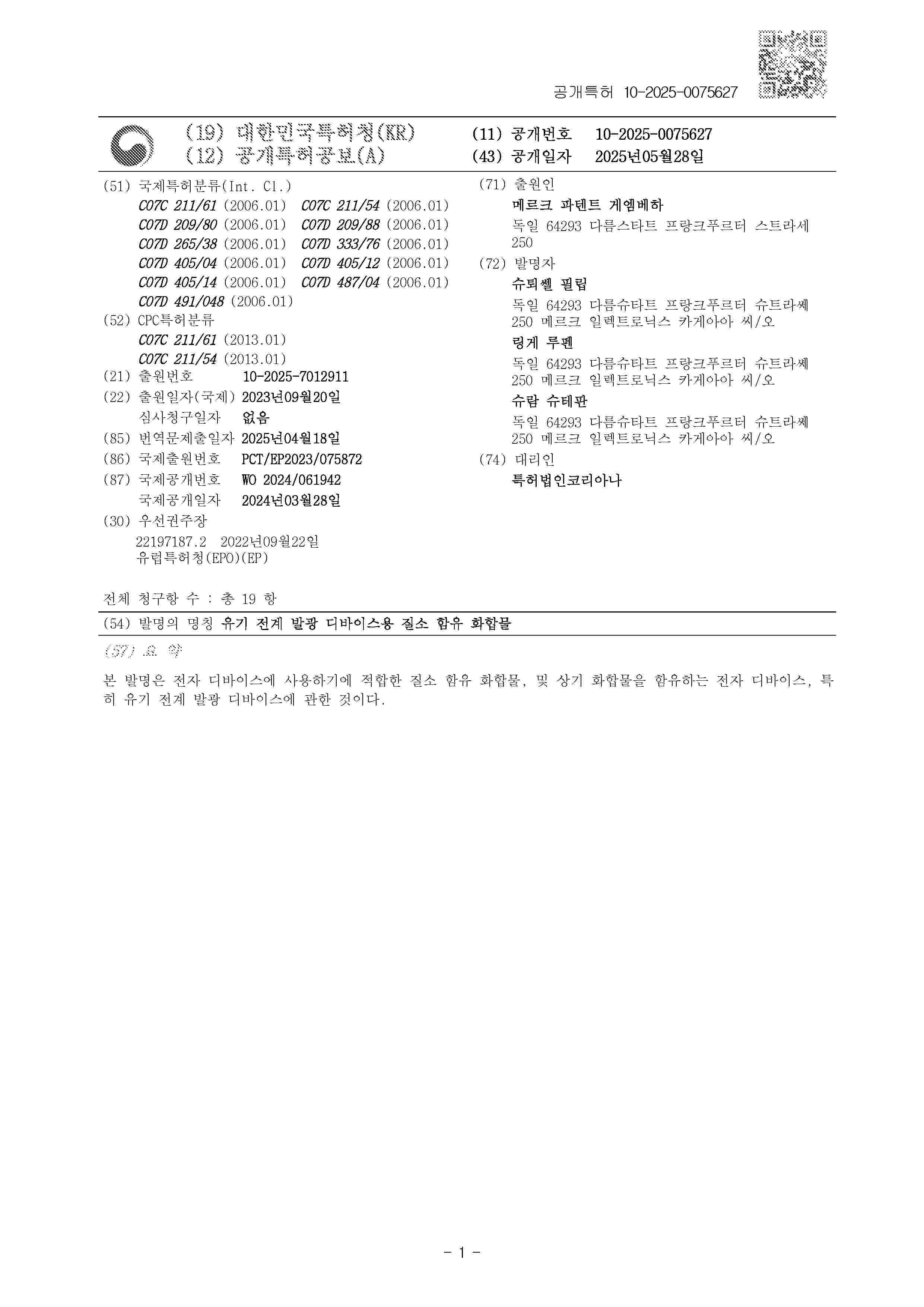
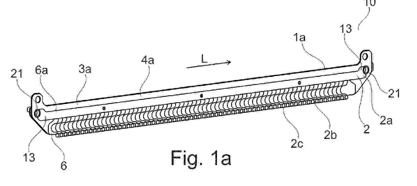
Resumen de: WO2024061746A1
The invention relates to a solar module (19) and a solar installation (37) made of multiple solar modules. The solar module has multiple 3TT solar cells (11), which are wired together in order to form at least one string (21), and at least two current input connections (27) at a current input of the solar module and/or at least two current output connections (29) at a current output of the solar module. Each 3TT solar cell has a stack comprising a top cell (3) and a bottom cell (5) arranged under the top cell, and each 3TT solar cell has a top contact (13), a bottom contact (15), and a central tap contact (17) as terminal contacts. A first current input connection (27') of the current input connections (27) is at least connected to one of the terminal contacts of a first 3TT solar cell (11') lying closest to the current input, and a second current input connection (27") of the current input connections (27) is at least connected to one of the terminal contacts of a second 3TT solar cell adjoining the first 3TT solar cell, and/or a first current output connection (29') of the current output connections is at least connected to one of the terminal contacts of a final 3TT solar cell (11") lying closest to the current output, and a second current output connection (29") of the current output connections is at least connected to one of the terminal contacts of a penultimate 3TT solar cell adjoining the final 3TT solar cell. The aforementioned wiring allows, among others, a substan
Resumen de: WO2024061714A1
The invention relates to a method for testing at least one bypass diode (4) in a photovoltaic apparatus (100) comprising at least one photovoltaic module (1) in operation, the photovoltaic module (1) comprising at least one string (2) of photovoltaic cells (3) that are connected to a bypass diode (4) dedicated to this string (2), the method comprising: a. shading some of the cells (3) of the string (2) so as to bring about a bypass through the diode (4), the bypass bringing about an increase in the temperature of the diode (4) if the diode (4) is in an operational state; b. measuring at least one temperature of the diode (4); and c. comparing the measured temperature with a threshold in order to infer a state of the diode (4).
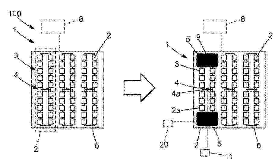
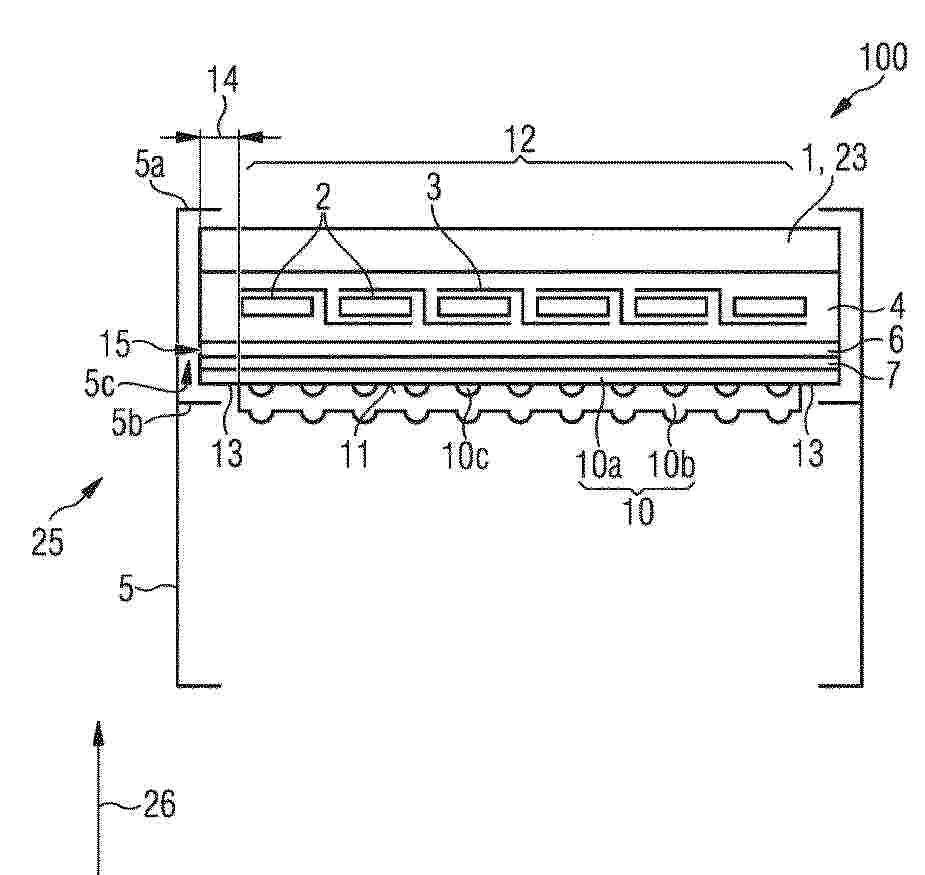
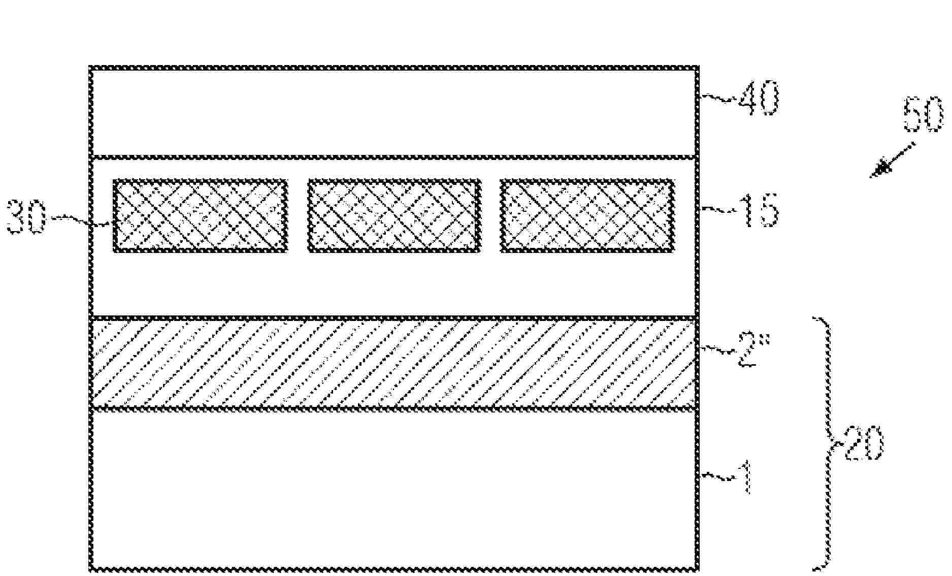
Resumen de: CN120051931A
The invention relates to a photovoltaic thermal module (100) comprising a plurality of solar cells (2) and a planar heat sink (10), the planar heat sink (10) being based on at least one inorganic material and comprising a plurality of cooling channels (10c); wherein the planar heat sink comprises two plates (10a, 10b), between which a cooling channel (10c) is formed; wherein a first panel (10a) of the panels facing the solar cells (2) is flat; wherein the cooling channel (10c) is defined by a second plate (10b) of the plates facing away from the solar cells (2); and wherein the second plate (10b) is arranged on the main surface (11) of the first plate (10a) such that the first region (12) of the first plate (10a) is covered by the second plate (10b) and the second region (13) of the first plate (10a) is free of the second plate (10b).
Resumen de: WO2024061552A1
The invention relates to a solar cell module, having a plurality of photovoltaic solar cells having electrically contactable rear surfaces, wherein the solar cells are arranged in a matrix shingle arrangement, which has a plurality of solar cell rows arranged spatially in parallel, each having a plurality of solar cells, wherein the solar cell rows are arranged to overlap in overlapping regions so that the rear sides of the solar cells of one solar cell row partially overlap the front sides of the solar cells of an adjacent solar cell row, and the solar cells are arranged in such a way that at least one rear side of a solar cell of a solar cell row partially overlaps the front sides of at least two solar cells of an adjacent solar cell row. The invention is characterised in that at least one solar cell row has an electrically conductive cross-connector covering at least 50% of the rear sides of at least the non-edge solar cells of the solar cell row and makes electrical contact therewith.
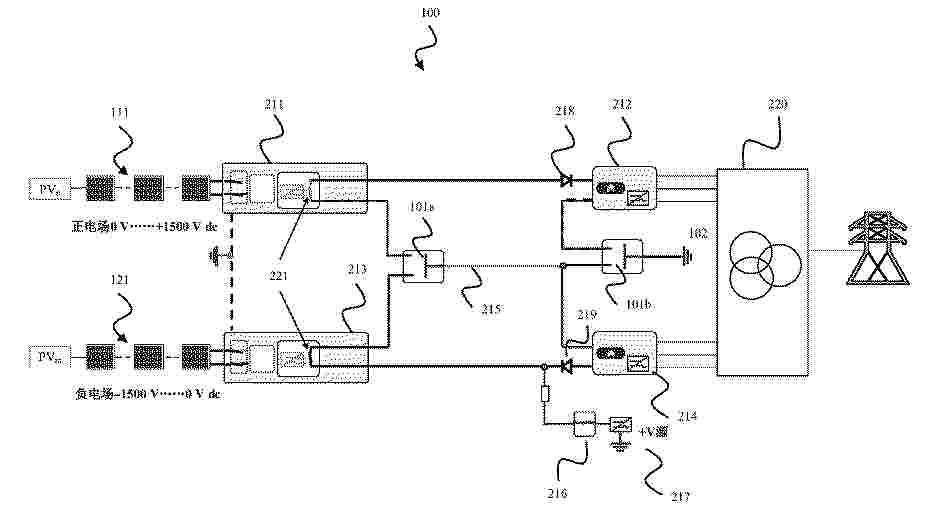
Resumen de: CN119948718A
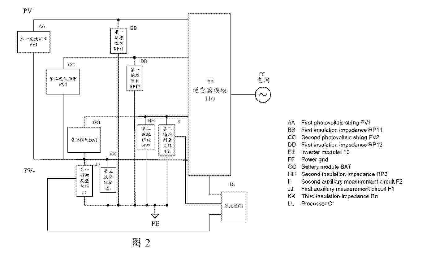
The present invention relates to a power supply system and a power generation system based on photovoltaic (PV). The present invention proposes a power supply system having two PV-based power generation systems combined together. A first power generation system of the power supply system includes one or more first PV strings and includes a first power conversion system connected to the one or more first PV strings. A second power generation system of the power supply system comprises one or more second PV strings and comprises a second power conversion system, and the second power conversion system is connected to the one or more second PV strings; the power supply system further includes one or more switches for selectively connecting and disconnecting the first power conversion system to and from the second power conversion system, and selectively connecting and disconnecting the first power conversion system and the second power conversion system to and from ground.
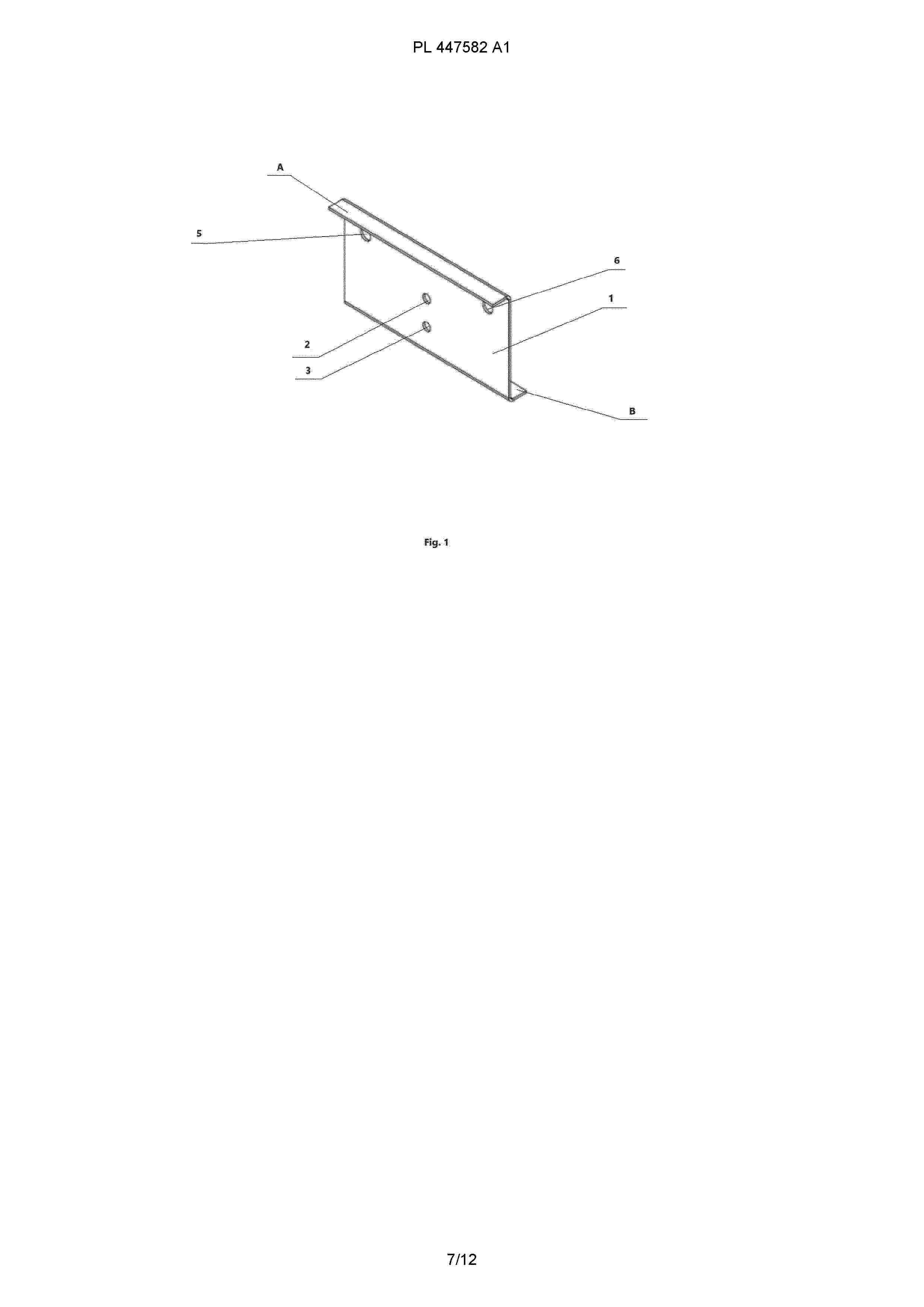
Resumen de: PL447582A1
Przedmiotem zgłoszenia jest łącznik do dwuspadowych konstrukcji wsporczych paneli fotowoltaicznych, w szczególności ustawionych w układzie wschód zachód. Łącznik do dwuspadowych konstrukcji wsporczych paneli fotowoltaicznych, gdzie dwie przeciwległe płaszczyzny z panelami posadowione są na konstrukcji z profili wspartych na trzech rzędach słupów podporowych, a jeden środkowy rząd jest wspólny charakteryzuje się tym, że łącznik ma kształt zetownika (1), którego górna i dolna krawędź (A i B) są wygięte w przeciwległych kierunkach pod kątem zasadniczo 90° w osi płytki umieszone są co najmniej dwa otwory (2, 3) do mocowania podpory (4), a po bokach na płaszczyźnie płytki umieszczone są po co najmniej dwa otwory (5, 6) do mocowanie bocznych profili wpierających panele fotowoltaiczne.
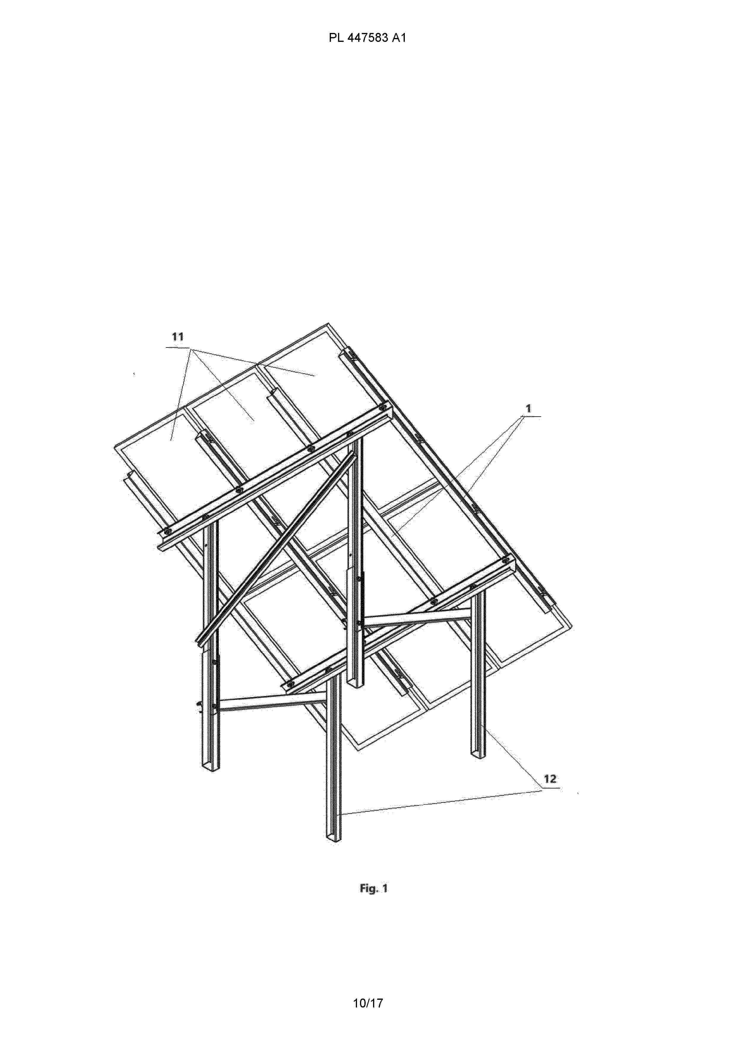
Resumen de: PL447583A1
Przedmiotem zgłoszenia jest system i sposób mocowania paneli fotowoltaicznych do konstrukcji wsporczej. System mocowania paneli fotowoltaicznych do konstrukcji wsporczej, gdzie panele fotowoltaiczne układa się obok siebie na konstrukcji wsporczej wykonanej z profili ułożonych pod krawędziami paneli charakteryzuje się tym, że profile (1) stanowiące część konstrukcji wsporczej na boku A, na którym układa się panele fotowoltaiczne mają podłużne otwory (2) o długości o długości większej niż nakrętka (10), gdzie na jednym boku każdego otworu (2) jest zasadniczo półokrągłe wcięcie (3) o średnicy odpowiadającej co najmniej średnicy śruby mocującej (5), a na śrubę mocującą panele nakręcana jest nakrętka (10) o kształcie trapezu, której krótsze boki są równolegle, przy czym odległość między krótszymi bokami poziomego przekroju nakrętki odpowiada wewnętrznej szerokości boku A profilu (1).
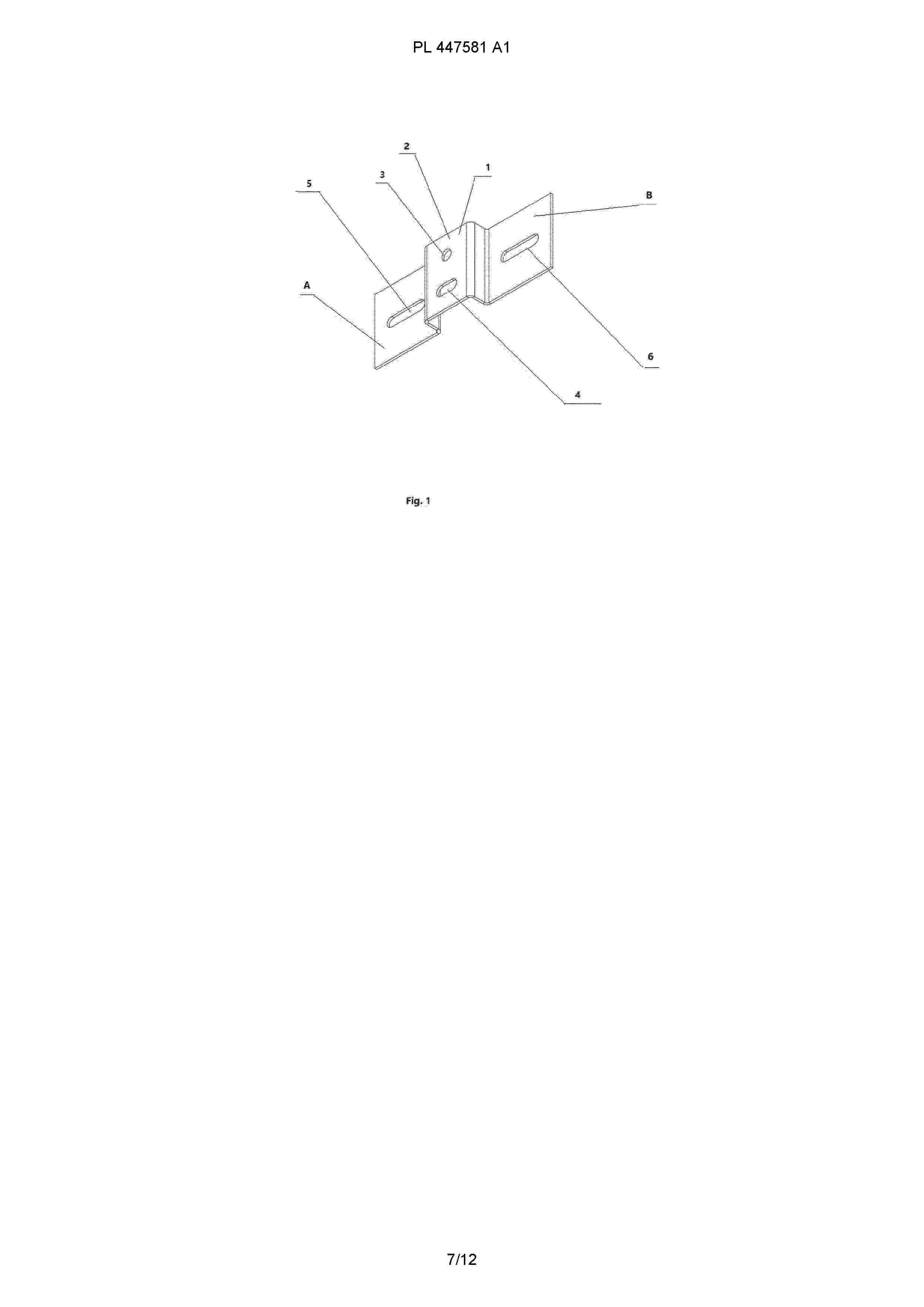
Resumen de: PL447581A1
Uchwyt do montażu konstrukcji wsporczych mający postać płytki prostokątnej w kształcie omegi charakteryzuje się tym, że w środkowej części występują dwa zagięcia płytki pod kątem 90° tworzące na odcinku stanowiącym zasadniczo 1/3 szerokości płytki (1) płaski występ (2), gdzie w osi płaskiego występu (2) umieszczane są dwa otwory, przy czym górny otwór (3) jest zasadniczo okrągły, a dolny otwór ma kształt poziomej elipsy (4), a na bocznych elementach uchwytu (A, B) umieszczone są symetrycznie pojedyncze poziome otwory (5, 6) w kształcie zasadniczo eliptycznym.
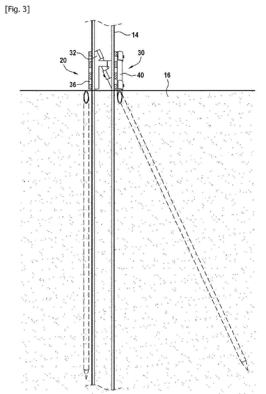
Resumen de: FR3158604A1
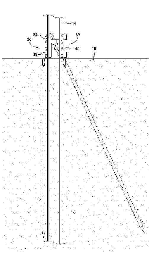
Structure de support d’au moins un panneau solaire, comprenant au moins un poteau de support (14) muni de moyens d’ancrage (20) dans le sol (16), les moyens d’ancrage (20) comprenant une attache (30) associée à des pieux d’ancrage (40) à enfoncer dans le sol, dans laquelle le poteau de support (14) s’étend au-delà de l’attache (30), à l’opposé de l’au moins un panneau solaire, pour son enfoncement dans le sol (16). Figure pour l’abrégé : Fig. 3
Resumen de: US2025238054A1
A finger-worn wearable ring device may include a ring-shaped housing, a printed circuit board, and a sensor module that includes one or more light-emitting components and one or more light-receiving components. The wearable ring device may further include a communication module configured to wirelessly communicate with an application executable on a user device.
Resumen de: US2025238053A1
A finger-worn wearable ring device may include a ring-shaped housing, a printed circuit board, and a sensor module that includes one or more light-emitting components and one or more light-receiving components. The wearable ring device may further include a communication module configured to wirelessly communicate with an application executable on a user device.
Resumen de: US2025237290A1
A solar bracket with a damping mechanism is provided and includes: a bracket structure including a fixed component and a rotating component; a solar panel installed on the rotating component; and a damping mechanism including a rotating assembly and a damping component. The rotating assembly includes a first rotating part and a second rotating part, the first rotating part is fixedly installed on the rotating component, the second rotating part is connected to the damping component, the first rotating part is transmitted and connected to the second rotating part, and a rotation radius of the first rotating part is greater than that of the second rotating part, when the rotating component drives the first rotating part to rotate, the first rotating part drives the second rotating part to rotate, and the second rotating part drives the damping component to move to limit a rotation speed of the rotating component.
Resumen de: US2025237268A1
A first embodiment of a torque tube coupler may include an outer body that includes a first abutting surface and a second abutting surface adjacent to the first abutting surface. Set screws may be inserted into one or more channels of the first abutting surface. Tightening the set screws may force the abutting surfaces away from each other and the outer body to press against an inner surface of a torque tube. Another embodiment of the torque tube coupler may include a central ring sized based on a size of a torque tube. The torque tube coupler may also include a set of fingers that extend away from a first side of the central ring and are shaped to flex radially outward. The torque tube coupler may include a core disposed within the set of fingers that, when drawn towards the central ring, causes the fingers to flex radially outwards.
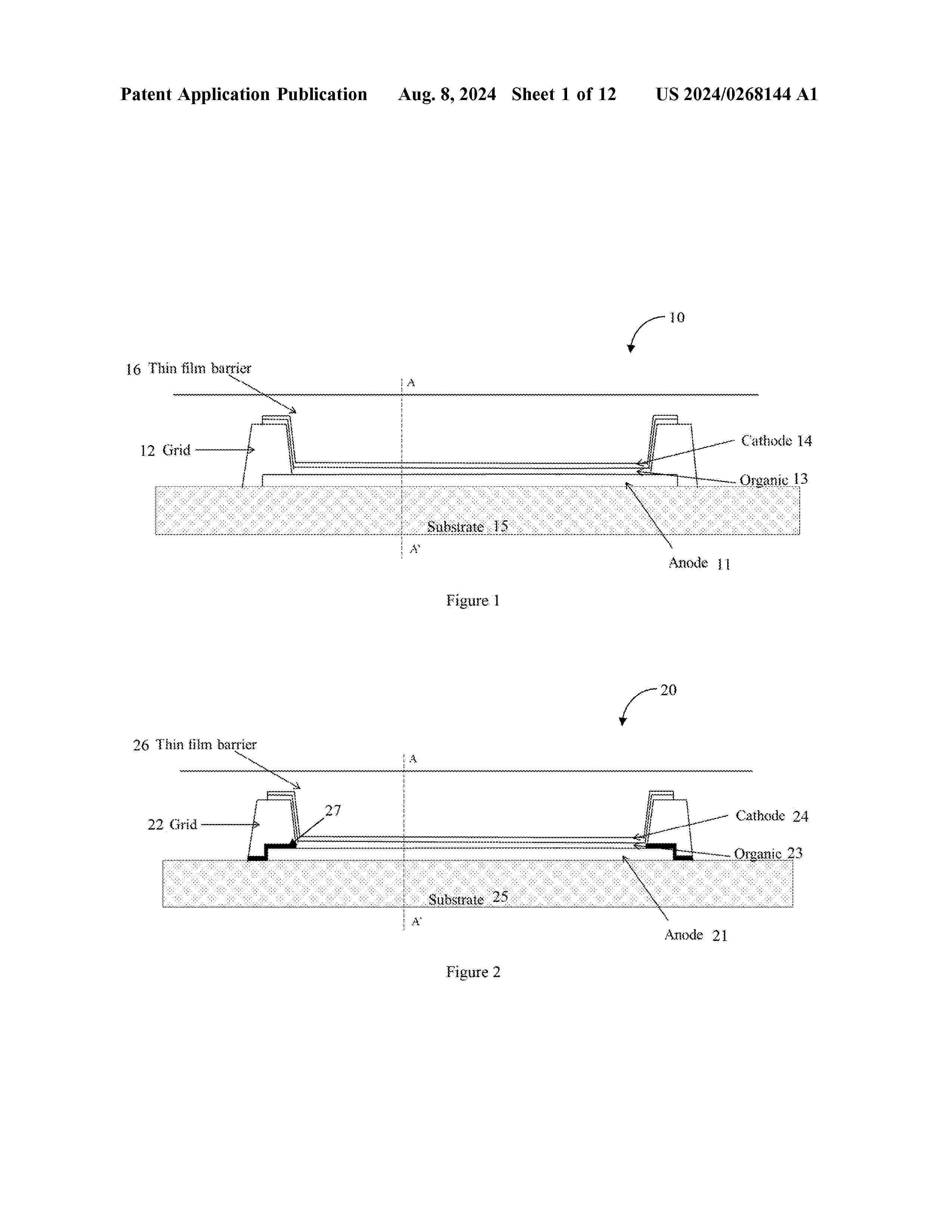
Resumen de: US2025241140A1
An organic light emitting device is provided which includes a plurality of organic light emitting diode (OLED) pixels disposed over the substrate. A first barrier element, disposed over the substrate and forming an insulating grid surrounding one or more OLED pixels, provides an edge seal for each OLED pixel. A second barrier element, disposed over one or more of the OLED pixels and in contact with the first barrier element, encapsulates the OLED pixel to provide a top seal.
Resumen de: US2025241084A1
A method of manufacturing an optoelectronic or photovoltaic device, including the following successive steps: a) forming, by PLD deposition, an active layer comprising a perovskite material on the upper side of a first charge transport layer; b) depositing, by PLD, a second charge-transport layer of inorganic material on the top face of the active layer.
Resumen de: WO2025155550A1
A solar module frame is configured to bound a plurlaity of photovoltaic cells. This solar module frame includes a first sidewall at a first side of the frame and a second sidewall at a second side of the frame. Extending out from the first sidewall is a first outward facing lower flange that includes at least one fastening aperture, and extending out from the first sidewall is a first inward facing upper flange that defines a first side photovoltaic cell receptacle. Extending out from the second sidewall is a second outward facing lower flange that includes at least one fastening aperture, and extending out from the second sidewall is a second inward facing upper flange that defines a second side photovoltaic cell receptacle.
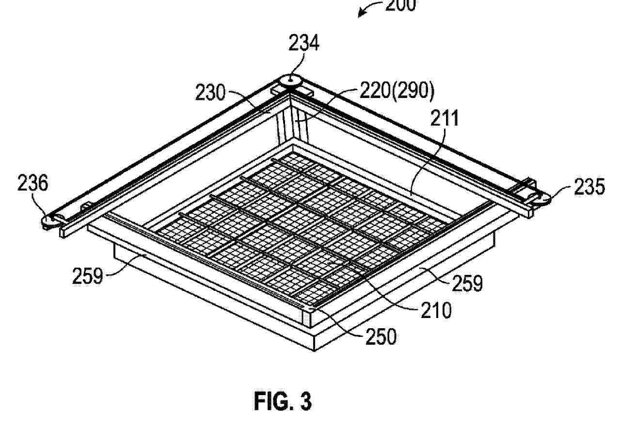
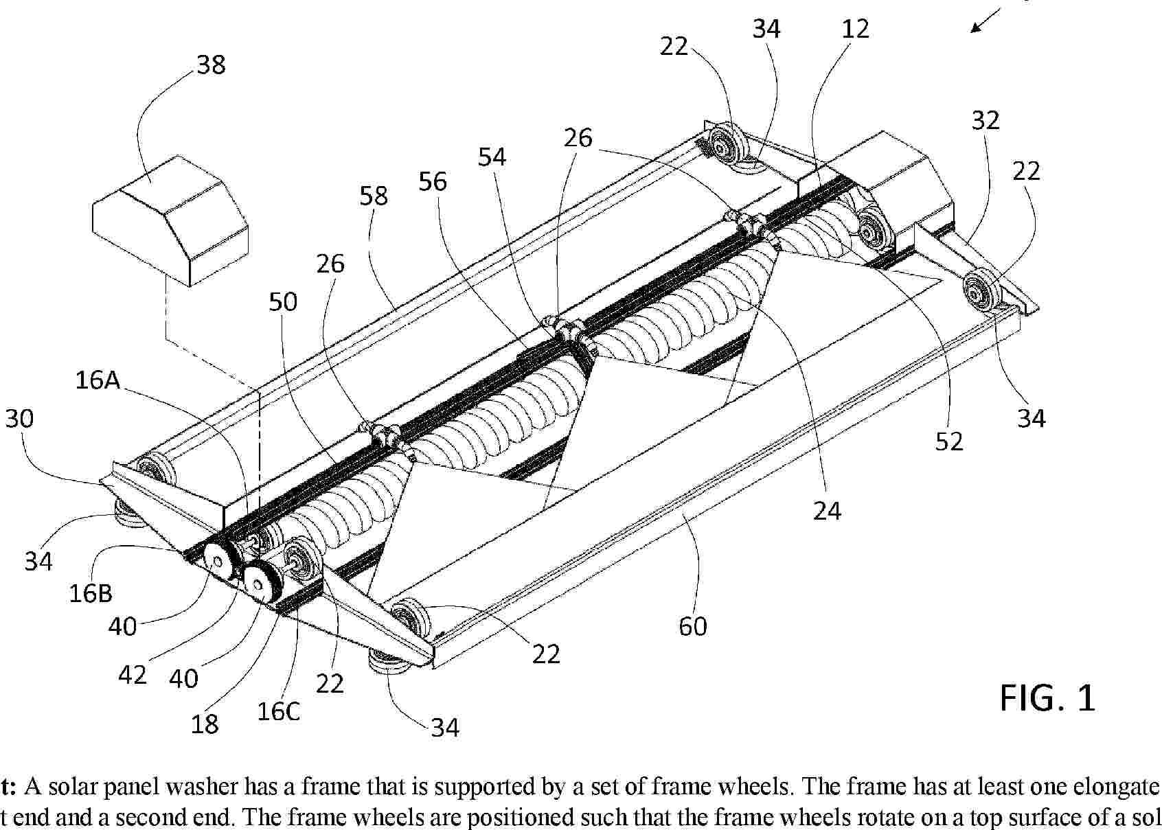
Resumen de: WO2025155536A1
Systems and cleaners for cleaning a solar panel (210) include a cleaner (200). The cleaner (200) includes a fixed arm (230), a moving arm (250) and an actuator (290). The fixed arm (230) comprises a first fixed bar and a second fixed bar which are connected with each other at a connecting end and form an angle to each other. The moving arm (250) includes a first moving bar and a second moving bar, which are connected to each other at a connecting end and form an angle to each other. The actuator (290) is configured to drive the moving arm (250) to move on the surface of the solar panel (210) along both the first fixed bar and the second fixed bar toward the connecting end of the first fixed bar and the second fixed bar.
Resumen de: WO2025155442A1
A self-centering rail includes a first side portion and a second side portion that is opposite the first side portion. The first side portion is configured to couple to a first solar module frame when a first flange of the first solar module frame is received at the first rail clamp and the second rail clamp and when a frame self-centering member of the first solar module frame is received at the first rail self-centering member. The second side portion is configured to couple to a second solar module frame when a second flange of the second solar module frame is received at the third rail clamp and the fourth rail clamp and when a frame self-centering member of the second solar module frame is received at the second rail self-centering member.
Resumen de: WO2025155492A1
Tandem photovoltaic devices and strings of photovoltaic devices can include structural configurations to facilitate improved diagnostic testing and provide module-level bypass. Also provided are methods of performing diagnostic tests.
Resumen de: WO2025153508A1
The present invention relates to a test element (10) for disconnectable electrical contacting of an electrically conductive substrate, in particular of a busbar-less solar cell, having two preferably slat-shaped mounting rails (1a, 1b) with at least one slat-shaped test rail (2) arranged therebetween, which has a main body (2a) and a plurality of contact elements (2c) formed integrally with the main body and arranged on one side thereof.
Resumen de: WO2025153978A1
The present invention relates to a solar roof panel (1) comprising - a base structure (2), - photovoltaic cells (3) provided in top of base structure (2), - a wiring (4) of photovoltaic cells (3), - connection points (5) comprising electrically conductive bolts (6), - a protective layer (7) provided on top of the photovoltaic cells (3) wherein the solar roof panel (1) is a self supporting structure, suitable as a roof covering The present invention further relates to solar roof system comprising at least two solar roof panels (1)
Resumen de: WO2025153859A1
System for the installation of photovoltaic systems on flat surfaces, comprising : a plurality of longitudinal metal section bars (1) arranged in parallel to each other and in orthogonal direction to the one of the photovoltaic modules arrays, each one being introduced in a plurality of lower support elements (7), slidingly associated to said section bars (1) and provided with blocking means of the respective axial position to said longitudinal section bars; a bearing element (9) associated to each of said lower support elements; support elements (8, 14) of the photovoltaic modules, each fastened on a respective lower support element (7) so to be able to change their own tilt angle to the vertical and configured to allow the fastening of the frame of a photovoltaic module, said bearing elements (9), said support elements (8, 14) and said lower support elements (7) being provided with snap-fit type integrated fixing means, which allow their respective fastening without using tools.
Resumen de: US2025241194A1
A perovskite-based semi-transparent photovoltaic cell (or solar cell) wherein the photoactive layer of perovskite includes at least one polyacrylic acid in an amount greater than or equal to 3% by weight, preferably between 4% by weight and 15% by weight, more preferably between 4.5% by weight and 12% by weight, with respect to the total weight of the perovskite precursors.The perovskite-based semi-transparent photovoltaic cell (or solar cell) can be advantageously used in various applications that require the production of electrical energy through the exploitation of light energy, especially the energy of solar radiation such as, for example: building integrated photo voltaic (BIPV); photovoltaic windows; greenhouses; photo-bioreactors; noise barriers; lighting engineering; design; advertising; automobile industry. The perovskite-based semi-transparent photovoltaic cell (or solar cell) can be used both in stand alone mode and in modular systems.
Resumen de: US2025241195A1
The present invention relates to a compound of formula (I), to its use in electronic devices, to methods for producing said compound, and to electronic devices containing the compound.
Resumen de: US2025241073A1
Described is a flexible composite strip including a flexible printed circuit comprising at least a first and a second conductor track, a plurality of groups of photovoltaic cells being connected in parallel to said first and second tracks for supplying them; the composite strip comprises a plurality of soldering pads at which the first and second conductor tracks are accessible; the flexible composite strip is configured to be cut at the soldering pads.
Resumen de: US2025239967A1
A solar panel washer has a frame that is supported by a set of frame wheels. The frame has at least one elongate support that has a first end and a second end. The frame wheels are positioned such that the frame wheels rotate on a top surface of a solar panel to allow the frame to move along the solar panel or a set of aligned solar panels. At least one nozzle is positioned on the frame. The at least one nozzle is attached to a hose such that a cleaning solution is sprayed onto the top surface of the solar panel. At least one brush is supported on the frame such that it contacts the top surface of the solar panel.
Resumen de: US2025239969A1
A system includes a plurality of photovoltaic modules installed and arranged in an array on a roof deck. Each of the photovoltaic modules includes a wire cover bracket configured to receive at least one electrical component. A rapid shutdown device is electrically connected to the at least one electrical component. The rapid shutdown device is configured to reduce an electrical voltage of the system to a predetermined voltage level. At least one visible indicator is electrically connected to the plurality of photovoltaic modules. The at least one visible indicator is activated when the electrical voltage of the system is less than or equal to the predetermined voltage level.
Resumen de: US2025239966A1
A solar module frame is configured to bound a plurality of photovoltaic cells. This solar module frame includes a first sidewall at a first side of the frame and a second sidewall at a second side of the frame. Extending out from the first sidewall is a first outward facing lower flange that includes at least one fastening aperture, and extending out from the first sidewall is a first inward facing upper flange that defines a first side photovoltaic cell receptacle. Extending out from the second sidewall is a second outward facing lower flange that includes at least one fastening aperture, and extending out from the second sidewall is a second inward facing upper flange that defines a second side photovoltaic cell receptacle.
Resumen de: US2025239963A1
A support structure for solar trackers with thermal expansion mitigation includes a frame rotatably coupled to one or more ground piles. The support structure further includes a pivot bracket rotatably coupled to a portion of the frame with the pivot bracket including a pivot pin to which torque tube clamps are rotatably coupled. The torque tube clamps are affixed to a torque tube and solar modules are affixed to the torque tube via one or more mounting brackets. Thermal expansion/contraction of the torque tube is translated into rotational movement of the frame relative to the one or more ground piles via the rotatable couplings including the pivot bracket. The rotational movement of the frame relative to the one or more ground piles enables the torque tube to expand/contract while mitigating mechanical stress of the support structure.
Resumen de: US2025239964A1
A solar tracker, solar array, and method of designing a solar tracker or array including a plurality of piers, a torque tube supported by the piers, each pier having a common reveal from the earth and the torque tube has a relative angle from a first pier to a second pier of between 0.25 and about 0.75 degrees.
Resumen de: US2025239965A1
In an aspect, the present disclosure describes a method comprising using at least one robot to fully autonomously position and assemble at least one solar module and its supporting structure at a sensed geolocation without aid from a user.
Resumen de: WO2025155693A1
A system includes a first photovoltaic module and a second photovoltaic module installed and arranged in an array on the roof deck. Each of the photovoltaic modules includes a first end, a second end opposite the first end, and a first location between the first end and the second end, a first plurality of solar cells, a second plurality of solar cells, an encapsulant layer encapsulating the first and second plurality of solar cells, a frontsheet, and a backsheet. The photovoltaic modules include a first portion and a second portion. The first portion extends between the first end and the first location, and the second portion extends between the first location and the second end. The second portion includes a wireway. The first plurality of solar cells is positioned within the first portion, and the second plurality of solar cells is positioned within the second portion.
Resumen de: WO2025155319A2
The present disclosure is generally related to photonic crystals, for example, for thermophotovoltaic power generation or other applications. Some aspects are directed to articles having multiple substrates that are used to contain vacuum or interior regions, for example, containing a photonic crystal. These articles may be heated in some embodiments by substantial amounts, without allowing leaks to occur into such regions. For instance, in some cases, the substrates may have similar coefficients of thermal expansion, which may expand in a substantially uniform manner to maintain physical contact without leaking. In some cases, a substrate may comprise sapphire and/or another IR-transparent material, e.g., to transmit emissions from the photonic crystal. In some cases, a substrate may comprise niobium and/or another metal, which may exhibit similar thermal expansion as sapphire. Other aspects are generally directed to methods of making or using the articles, kits including such articles, or the like.
Resumen de: WO2025154885A1
A method for automatically mapping an inverter of a photovoltaic module, according to one aspect, may comprise the steps of: receiving an identification information list of micro inverters corresponding to a respective plurality of provided photovoltaic modules; receiving a first image including a plurality of first codes from a user; recognizing the first codes so as to obtain position information and identification information of micro inverters corresponding to the first codes; generating a first layout diagram of the micro inverters on the basis of the obtained position information and identification information; comparing the number of pieces of identification information of the micro inverters in the identification information list to the number of pieces of identification information corresponding to the recognized plurality of first codes so that, if there is no match, an alarm is sent and information of a position on the first layout diagram of a micro inverter corresponding to an unrecognized first code is recommended; and modifying the first layout diagram on the basis of the recommended position information.
Resumen de: WO2025154894A1
The present invention relates to a microinverter which comprises: a case having an inner space; a circuit board disposed inside the case; a first connector supported by the case and directly connected to one side of the circuit board; and a second connector supported by the case and directly connected to another side of the circuit board.
Resumen de: WO2025154614A1
Provided is a photovoltaic power generation system that allows easy terminal box maintenance. A photovoltaic power generation system (1) according to one embodiment of the present invention comprises: a solar cell module (10) having a photovoltaic power generation cell (15); and a terminal box (30) connected to the photovoltaic power generation cell (15) via wiring (21). The terminal box (30) is provided at a position spaced apart from the solar cell module (10).
Resumen de: US2025239968A1
The existing solar power generation panel installed on the roof of a smart farm has problems that an amount of light transmitted into the greenhouse is significantly reduced and the transmitted light is also not uniform, and thus an area where the solar power generation panels are installed is shaded and a shadow occurs. For these reasons, an installation distribution rate of solar power generation panels installed on the roofs of smart farms is very low. A solar power generation system for smart farms includes a three-dimensional (3D) optical filter window with a function of selectively transmitting light of wavelengths applicable to smart farms, and a solar power generation module provided to protrude above an optical filter of the optical filter window to increase solar power use efficiency. Since shading occurs when a solar power generation panel is used in a smart farm to affect cultivation, there is a problem in that the solar power generation panel cannot be used on the roof of a smart farm. However, according to the above-described configuration of the present invention, the optical filter window equipped with a dichroic light filter is used to solve this problem so that there is an effect of operating a smart farm more economically.
Resumen de: US2025239932A1
This application provides a direct current conversion circuit and a photovoltaic inverter. The direct current conversion circuit includes an RC circuit, and a first direct current conversion unit and a second direct current conversion unit that are mutually connected in parallel. The RC circuit includes a resistor and a capacitor that are connected in series. Two ends of the RC circuit are respectively connected to one end of a first switching transistor in the first direct current conversion unit and one end of a second switching transistor in the second direct current conversion unit. When a state of the first switching transistor or the second switching transistor is switched, the other switching transistor remains in an on or off state.
Resumen de: US2025239961A1
A portable tent device with electrical power supply is provided. The device is comprised of a frame including at least one vertical frame member and one horizontal frame member. The vertical frame member may include a foot that can be repositioned or adjusted in angle and features an opening for securing the device with a fastener like a ground stake. Additionally, the device incorporates a roof comprised of at least one solar panel that powers an integrated battery. This battery supplies energy to a power outlet that may be positioned on the vertical frame member, to enable the connection and operation of various electrical devices. The device may also include a side wall, connectable to the frame via various fasteners, that is also equipped with additional solar panels that contribute to the power supply, enhancing the device's functionality in providing shade and weather protection.
Resumen de: US2025239962A1
A support structure for at least one solar panel, comprising at least one support post provided with a fastener associated with anchor piles to be driven into soil, wherein the support post extends beyond the fastener, opposite to the at least one solar panel, in order to be driven into the soil. The fastener may comprise a fitting added onto the support post. The fastener may comprise two half-fittings. The two half-fittings may be assembled to each other by one or more of the anchor piles. The support post may extend beyond the fastener, opposite to the at least one solar panel, by at least 50 cm.
Resumen de: WO2025152736A1
Disclosed are a curved solar panel (11), a photovoltaic array (10) and a solar energy system (100a, 100b). The curved solar panel (11) comprises, successively connected in a first direction, crest parts (11p) and trough parts (11r). The curved solar panel (11) further comprises: a power generation region (11e) provided with a power generation layer (113); and a first non-power generation region (11a) and a second non-power generation region (11b), which are respectively located on two opposite sides of the power generation region (11e) in the first direction, the upper part of the first non-power generation region (11a) being used for connecting to a second non-power generation region (11b) of an adjacent curved surface solar panel (11). The width of the first non-power generation region (11a) in the first direction is defined as X1, the width of the second non-power generation region (11b) in the first direction is defined as X2, and the thickness of the curved solar panel (11) is defined as W, X1, X2 and W satisfying: X1≥X2+W.
Resumen de: WO2025152683A1
A frame structure, belonging to the technical field of solar photovoltaics. The frame structure comprises frames, wherein each frame comprises a cavity; and each frame is provided with a boss portion, the boss portion comprising an inner recessed surface recessed outside the cavity and an outer protruding surface protruding inside the cavity, and the boss portion being provided with a removal hole running through the inner recessed surface and the outer protruding surface, the removal hole being configured to allow a removal tool to penetrate into the cavity. According to the frame structure provided in the present invention, by means of a removal tool penetrating into the cavity, the outer protruding surface can be deformed by pressing same towards the inner recessed surface through the removal tool, thereby flattening the boss portion; that is, the limit of the boss portion is disabled, thereby facilitating detachment, without causing damage, achieving reutilization and saving resources.
Resumen de: WO2025152725A1
A photovoltaic power generation system (10), comprising at least one photovoltaic power generation module (1010). The photovoltaic power generation module comprises at least two photovoltaic modules (11) and an adapter cable (1011). Each photovoltaic module comprises a connecting cable (1035b); the input end of the connecting cable is connected to a positive electrode (1033a) and a negative electrode (1033b) of the corresponding photovoltaic module, two male connectors or two female connectors are arranged at the output end of the connecting cable, and the two male connectors or the two female connectors are respectively a positive electrode and a negative electrode of the output end of the connecting cable; the connecting cables of the at least two photovoltaic modules are connected to a direct-current bus by means of the adapter cable. The adapter cable comprises at least two sub-connecting ends (1011b) adapted to be correspondingly connected to the output ends of the connecting cables.
Resumen de: WO2025152797A1
A curved photovoltaic tile (110) is disclosed. The curved photovoltaic tile (110) comprises: a light-transmitting panel (1101); a photovoltaic cell layer (1104), which is located on one side of the light-transmitting panel (1101); an insulating layer (1106), which is located on the side of the photovoltaic cell layer (1104) away from the light-transmitting panel (1101); and a metal back plate (1108), which is arranged on the side of the insulating layer (1106) away from the photovoltaic cell layer (1104).
Resumen de: US2025239960A1
A roof-based system for electric vehicles can be equipped with an array of wind turbines and expandable solar panels that are designed to generate electricity for the operation of electric vehicle. The wind turbines can harness the power of the wind while the vehicle is driving, and the solar panels can be fully extended when the vehicle is parked, maximizing the conversion of solar energy into electrical power. The generated energy can then be stored in the vehicle's batteries, serving a dual purpose: it can either propel the electric vehicle or supply power for daily energy needs. This innovative roofing system represents a sustainable and eco-friendly solution that not only promotes renewable energy usage but also enhances the overall efficiency and eco-friendliness of electric vehicles.
Resumen de: US2025239885A1
An electric power system is disclosed herein. The electric power system may manage and store electric power and provide uninterrupted electric power, derived from a plurality of electric power sources, to an electric load. The electric power system may contain an energy storage unit and generator assembly. The electric power system may connect to a power grid and renewable energy sources, and may charge the energy storage unit using the power grid, renewable energy sources, and/or generator assembly. The electric power system may be configured to determine load power usage and environmental factors to automatically and continuously modify a charging protocol to, for example, provide high efficiency and/or self-sufficiency from the power grid. The electric power system may operate entirely off-grid and may provide electricity to the load without interruption to power.
Resumen de: US2025239854A1
A grid-forming control method with full-state virtual oscillator for photovoltaic and energy storage system includes: establishing a control model of the full-state virtual oscillator, where the control model of the full-state virtual oscillator includes a frequency and a voltage amplitude; establishing a constraint control model of a current inner loop; and according to the control model of the full-state virtual oscillator and the constraint control model of the current inner loop, adjusting control parameters of the full-state virtual oscillator, where the control parameters are used to control the stable operation of grid-forming photovoltaic and energy storage systems.
Resumen de: US2025239850A1
The present disclosure relates to systems, methods, software, hardware, and techniques for improving power resiliency of small compounds with an emphasis on wireless cell towers and data centers. The power resiliency measures relate to software solutions for power resilience, and hardware/software solutions for crisis mitigation.
Resumen de: US2025239787A1
A u-shaped splice that is used to connect two solar mounting rails, includes barbs that interact with the rails, requiring more force to remove the splice from the rails than the force required to insert the splice into the rails. Wedges, located at a mid-point between ends of the splice interact with the rails, creating an interference fit between the splice and the rails.
Resumen de: AU2023397954A1
Floating device for solar energy production comprising a plurality of connected solar panels (31) arranged at the surface of a polyhedron structure (11) with a top end (12) and a bottom end (13) defined by a frame structure av pipe elements (14) connected to one another at nodes (15) to form polygonal areas (16) constituing the areas at the suraface of the polyhedron structure (11) in which the solar panels (31) are mounted. Within the interior of said polyhedron structure(11), a central buoyancy body (20) is arranged in a manner allowing vertical displacement thereof.
Resumen de: WO2025152619A1
The present invention relates to the technical field of solar cell packaging, and in particular, to a packaging layer structure of a perovskite solar cell module and a packaging method therefor. The packaging layer structure is obtained by means of a vapor deposition method, has a simple process flow, is easy to manufacture, and reduces the production costs. The uppermost second inorganic layer of a perovskite solar cell module achieves the effect of blocking oxygen, and a protection layer between the second inorganic layer and a metal electrode layer achieves the effect of protecting the structure and efficiency of a device. A first inorganic layer is provided between an electron transport layer and the metal electrode layer, so as to inhibit the increase in the defect state density and non-radiative recombination caused by internal ion migration, thereby increasing an open-circuit voltage, and thus playing a positive role in improving the energy conversion efficiency of the perovskite solar cell module, and also blocking water. In addition, for a perovskite cell module packaged using the packaging method provided in the present invention, the stability of water and oxygen is greatly improved, and the working stability of the perovskite cell module is also improved.
Resumen de: WO2025152592A1
A photovoltaic module (100) comprises: a photovoltaic member (110) having a first side edge (112), a second side edge (114), a third side edge (116), and a fourth side edge (118); and a first mounting base (130) and a second mounting base (140), wherein the second mounting base is provided with a mounting slot (142) and the first mounting base is arranged on the first side edge (112). The first mounting base (130) can be inserted into the mounting slot (142) in the direction from the fourth side edge (118) to the first side edge (112), and exit the mounting slot (142) in the direction from the first side edge (112) to the fourth side edge (118).
Resumen de: WO2025152318A1
A rotary damper (100), comprising: a bearing seat (1), a bearing (2), and an adjustment member. The bearing (2) is embedded in the bearing seat (1), and a chamber (10) accommodating a viscous fluid is provided between the bearing (2) and the bearing seat (1). The adjustment member is fixedly connected to the bearing (2), and extends into the chamber (10). The adjustment member can rotate in the chamber (10) synchronously with the bearing (2), and when rotation of the adjustment member causes the speed of the viscous fluid to change abruptly, the viscous fluid generates a viscous force, so as to impede continued movement of the adjustment member. The present invention further relates to a photovoltaic tracking support (300), comprising a main shaft (200) and the rotary damper (100). The main shaft (200) passes through the bearing (2), such that the bearing (2) is sleeved on the main shaft (200), thereby clamping the bearing (2) between the main shaft (200) and the bearing seat (1). The rotary damper can improve the stability of a photovoltaic tracking support product.
Resumen de: AU2023407207A1
The present disclosure provides provides a window unit for a building or structure. The window unit comprises a first panel having an area transparent for at least a portion of visible light. The window unit also comprises a second panel having an area transparent for at least a portion of visible light. The window unit further comprises a spacer spacing the first panel from the second panel. The spacer surrounds a space between the first and second panels. A first edge area of the first panel extends beyond a projection of the circumference of the spacer in a direction of a surface normal of the first panel. The window unit also comprises a housing incorporating at least one electric or electronic element which is indirectly or directly electrically coupled to at least one other electrical component positioned within the window unit. The housing is positioned at or near the spacer and at least partially within a projection of the circumference of the first edge area of the first panel in the direction of the surface normal of the first panel.
Resumen de: AU2024219392A1
-23- The disclosure relates to the field of new energy technology and provides a control method and a control device of a photovoltaic system. The photovoltaic system includes a photovoltaic string, an energy storage device, a photovoltaic inverter, and a power converter. The method includes: obtaining a current time and an state of charge(SOC)of the energy storage device; 5 checking whether the current time is in a preset charging period of the energy storage device, and checking whether the SOC of the energy storage device meets a charging condition to control the power converter; checking whether the current time is in a preset discharging period of the energy storage device, and checking whether the SOC of the energy storage device meets a discharging condition to control the power converter. The disclosure can directly implement the 10 charging/discharging control of the energy storage device without the need for a related apparatus to sample or communicate with a grid-connected end of the photovoltaic system, which is low in cost and simple in control. Moreover, since there is no information exchange with another apparatus, a third-party photovoltaic inverter apparatus can be better matched, and compatibility is strong. 15 The disclosure relates to the field of new energy technology and provides a control method and a control device of a photovoltaic system. The photovoltaic system includes a photovoltaic string, an energy storage device, a photovoltaic inverter, an
Resumen de: AU2025205027A1
Abstract The present invention relates to conjugates of π-electron-pair-donating heteroaromatic nitrogen- comprising drugs and pharmaceutically acceptable salts thereof, pharmaceutical compositions comprising said conjugates and the use of said conjugates as medicaments. Abstract The present invention relates to conjugates of m-electron-pair-donating heteroaromatic nitrogen- comprising drugs and pharmaceutically acceptable salts thereof, pharmaceutical compositions comprising said conjugates and the use of said conjugates as medicaments.
Resumen de: WO2025152304A1
Provided are an ethylene/α-olefin random copolymer and the use thereof. The ethylene/α-olefin random copolymer has the following features: (i) the molar content of a soluble fraction (SF) at 35°C or less, measured by means of elution under gradient heating, is 0.5-3%, wherein the soluble fraction has a weight-average molecular weight of less than or equal to 20,000 g/mol; and (ii) the total branch chain number per thousand carbon atoms in the chain structure of the copolymer is 25-85, and a relationship of highly linear fitting is formed between the branch chain number per thousand carbon atoms of chain segments with different molecular weights and the logarithms of the molecular weights of the chain segments of the copolymer, the determination coefficient R2 of fitting being greater than or equal to 0.75. The copolymer has a fast cross-linking speed and a high cross-linking degree when used in photovoltaic adhesive films, has improved processability, and enables obtained photovoltaic adhesive films to have high light transmittance and good sealing performance.
Resumen de: WO2025152223A1
A solar system (1000) and a cleaning robot system (2000). The solar system comprises: a solar panel (110); and a control mechanism (120), the control mechanism being connected to the solar panel, and the control mechanism being used for controlling, on the basis of acquired information, the solar panel and/or a first load mechanism related to the solar panel to execute a target event, wherein the first load mechanism is directly or indirectly powered by the solar panel. The solar system can realize automatic management of the solar panel and/or the first load mechanism, and is efficient and rapid.
Resumen de: WO2025152253A1
The present application relates to a method and system for zero feed-in control of a micro inverter monitoring gateway, and a medium. The method comprises: collecting a real-time electric energy value, productivity data and an electricity load value; determining a real-time output power control value by means of the real-time electric energy value and a preset electric energy set value; determining a real-time output power value by means of the real-time output power control value and the productivity data; and adjusting the output of a corresponding micro inverter by means of the real-time output power control value, so that the sum of real-time output power values is not greater than the electricity load value. The present application has the effect of realizing zero feed-in control.
Resumen de: WO2025152220A1
An organic compound, a light-emitting element and a display panel. The organic compound has a structure as represented by general formula (1).
Resumen de: WO2025152295A1
An insulation impedance measurement system and method, and an optical storage hybrid energy system. The insulation impedance measurement system is used for measuring the insulation impedance in an optical storage hybrid energy system. In the insulation impedance measurement system, one end of a first auxiliary measurement circuit is connected to a negative electrode of each photovoltaic string and a negative electrode of a battery module, one end of a second auxiliary measurement circuit is connected to a positive electrode of the battery module, and the other end of the first auxiliary measurement circuit and the other end of the second auxiliary measurement circuit are connected to a reference voltage end; a processor controls an inverter module (110) to set the output voltage of each photovoltaic string and the bus voltage of a line where the battery module is located, controls, on the basis of the set voltages, the first auxiliary measurement circuit and the second auxiliary measurement circuit to measure the voltages of the negative electrode of each photovoltaic string and of the negative electrode of the battery module for the reference voltage end, and calculates the impedance value of each insulation impedance.
Resumen de: WO2025152212A1
Provided are a foldable cover plate (2) and a vehicle (1). The foldable cover plate (2) is configured to be arranged at a trunk (1b) of the vehicle (1) to shield or open an opening of the trunk (1b). The foldable cover plate (2) comprises a plurality of cover plate assemblies (10) which are sequentially and rotatably connected, wherein each cover plate assembly (10) comprises a photovoltaic panel (11) and a base plate (12), the photovoltaic panels (11) being configured to absorb light energy and convert the light energy into electric energy, and any two adjacent cover plate assemblies (10) are electrically connected to each other; and in an arrangement direction of the plurality of cover plate assemblies (10), the cover plate assembly (10) arranged at one end is further configured to be electrically connected to an energy storage device (3) located inside the trunk (1b), so as to charge the energy storage device (3). The foldable cover plate (2) can not only shield the trunk (1b), but can also realize optical-electrical conversion, and can use the converted electric energy to charge the energy storage device (3) in the trunk (1b), thereby realizing the function of charging, such that the foldable cover plate (2) has diversified functions, and thus meets the requirements of users.
Resumen de: US2025236710A1
According to the present invention, an intermediate film for a backsheet for photovoltaic modules is provided, the intermediate film comprising a substrate film, for example, a PET film, and a partially cross-linked layer of coating resin. The corresponding method for producing such an intermediate film is also presented, which involves providing a substrate film, depositing and spreading a layer of coating resin on the substrate film, and partially cross-linking the layer of coating resin. According to this method, the cross-linking of the resin is stopped before it is completed so that the intermediate film is obtained, and it is finished during the subsequent process of laminating the intermediate film to the encapsulant of a photovoltaic module.
Resumen de: US2025236194A1
Solar+Storage Electric Vehicles (EV) Charging Carport (SSEVCC) is a prefabricated, ship-to-site, fully integrated, solar electric generator roof, energy storage system, power management system, EV charger carport designed to generate renewable electricity, store electricity, provide electricity for onsite EV charging, receive and provide electricity to/from Virtual Power Plants (VPP), Microgrids, and electric utility grids. The SSEVCC is designed to be a turnkey, with little additional onsite infrastructure required, deployment and rapid installation, solar plus energy storage EV charging carport for fleet parking and dispatch lots.
Resumen de: DE102024101472A1
Ein derartiges Fundamentsystem mit wenigstens einem Fundamentblock, der wenigstens eine Pfette für ein Trägerprofil einer Solarpanelhalterung aufweist, ist bekannt.Erfindungsgemäß ist als Fundamentblock ein in montiertem Zustand mit Schüttgut befülltes, kastenförmiges Behältnis mit einem Boden und von dem Boden aus nach oben abragenden Seitenwandungen vorgesehen, wobei an wenigstens zwei gegenüberliegenden Seitenwandungen auf einer zur Mitte des Behältnisses gewandten Innenseite jeweils eine in Hochrichtung nach oben über einen Behältnisrand abstehende Pfette befestigt ist.Einsatz für Freifeld-Photovoltaikanlagen
Resumen de: DE102024101570A1
Die vorliegende Erfindung bezieht sich auf ein Solardachpaneel (1) umfassend- eine Trägerstruktur (2)- Solarzellen (3) auf der Trägerstruktur (2)- Hauptleitungen (4) von Solarzellen (3)- Montagepunkte (5) für elektrisch leitende Verbindungselemente (6)- Schutzschicht (7) auf den Solarzellen (3)wobei das Solardachsystem (1) als selbsttragende Struktur ausgeführt ist und zur alleinigen Dacheindeckung genutzt werden kann.Die vorliegende Erfindung bezieht sich ferner auf ein System für ein Solardach umfassend mindestens zwei Solardachpaneele (1)
Resumen de: DE102024101602A1
Die vorliegende Erfindung betrifft eine Prüfelement (10) für die lösbare elektrische Kontaktierung eines elektrisch leitfähigen Substrats, insbesondere einer busbarlosen Solarzelle, aufweisend zwei vorzugsweise lamellenförmige Trägerschienen (1a,1b) mit wenigstens einer dazwischen angeordneten lamellenförmigen Prüfschiene (2) aufweisend einen Grundkörper (2a) und eine Mehrzahl daran einseitig angeordneter und integral mit dem Grundkörper ausgebildeter Kontaktelemente (2c).
Resumen de: EP4589842A1
Die Vorrichtung besteht aus Gliederketten (1-4) aus gelenkig miteinander verbundenen Gliedern (14), an denen oder in denen Rollenwagen längs dieser Gliederketten (1, 2) rollend geführt sind. Diese Rollenwagen für jede Gliederkette (1, 2) sind in Abständen zueinander in Längs- und Rollrichtung mit einer Spanngurte (11) fest verbunden. An diesen Rollenwagen sind Querstreben (5, 6) montiert, welche zwei Rollenwagen von benachbarten Gliederketten (1, 2) miteinander verbinden. An den parallel zueinander verlaufenden Querstreben (5, 6) zwischen Rollenwagen auf gleicher Höhe können ein oder mehrere Photovoltaik-Panels aufgelegt und mit den Querstreben (5, 6) verspannt werden. Für die Montage wird zunächst ein Seil mittels eines Überwurfsystems über die aufgerichtete Traglufthalle geworfen. Damit wird eine Gliederkette (1, 2) und über den Zenit der Traglufthalle gezogen, wonach die Gliederkette (1, 2) satt auf der Aussenmembran der Traglufthalle aufliegt. Weitere Gliederketten werden parallel dazu montiert. Dann wir für jede Gliederkette (1, 2) eine Spanngurte (11) mit daran festgeschraubten Rollenwagen in diese Gliederkette (1, 2) eingezogen. Die Rollenwagen auf gleicher Höhe werden mit Querstreben (5, 6) verbunden.
Resumen de: EP4588433A2
The present disclosure describes a wearable computing device (WCD) in the form of a ring that can be worn on the finger of a human user. In one example, a wearable computing device comprises: an interior wall; an exterior wall; a flexible printed circuit board disposed between the interior wall and the exterior wall; at least one component disposed on the flexible printed circuit board; and wherein at least one of the interior wall and the exterior wall defines a window that facilitates at least one of data transmission, battery recharge, and status indication
Resumen de: EP4589830A1
This application provides a direct current conversion circuit and a photovoltaic inverter. The direct current conversion circuit includes an RC circuit, and a first direct current conversion unit and a second direct current conversion unit that are mutually connected in parallel. The RC circuit includes a resistor and a capacitor that are connected in series. Two ends of the RC circuit are respectively connected to one end of a first switching transistor in the first direct current conversion unit and one end of a second switching transistor in the second direct current conversion unit. When a state of the first switching transistor or the second switching transistor is switched, the other switching transistor remains in an on or off state. The RC circuit is configured to absorb a spike voltage when the state of the first switching transistor or the second switching transistor is switched, to reduce a voltage change rate of the first switching transistor or the second switching transistor. This reduces circuit costs of the direct current conversion circuit, and circuit design complexity is low.
Resumen de: MX2025003561A
A bifacial photovoltaic structure includes a transparent substrate, a perovskite absorber layer overlaying the substrate, a transparent first composite conductor interposed between the substrate and the perovskite absorber layer, and a transparent second composite conductor disposed over the perovskite absorber layer. The first composite conductor includes a first set of metal lines, and a first conducting layer provided in contact with the metal lines, wherein the first set of metal lines is characterized by a first set of dimensions and a first metallic composition. The second composite conductor includes a second conducting layer, and a second set of metal lines provided in contact with the second conducting layer, wherein the second set of metal lines is characterized by a second set of dimensions and a second metallic composition. The dimensions and/or compositions of the first and second composite conductors are different.
Resumen de: EP4589843A1
A solar cell module includes a solar cell string sealed between a transparent substrate and a back surface protection member. The solar cell string includes solar cell connection units in each of which a plurality of solar cells adjacent in a first direction is connected in series with each other. Each of the solar cell connection units is provided with an output wiring member. The output wiring member extends to an outside through the back surface protection member. Outlets and a terminal box are positioned apart from each other in an in-plane direction of the back surface protection member.
Resumen de: EP4589844A1
A photovoltaic module includes a plurality of photovoltaic cell connection units in each of which a plurality of photovoltaic cells adjacent to each other in a first direction is connected in series with each other. Two of the photovoltaic cell connection units, the two being adjacent in a second direction orthogonal to the first direction, are connected in series with each other by bus bars to constitute a photovoltaic string. An end of an output wiring member is connected to a starting end or a terminating end of the photovoltaic cell connection unit, and another end of the output wiring member establishes electrical continuity with a terminal box. The terminal box includes bypass diodes, and each of the plurality of photovoltaic cell connection units is connected in parallel with corresponding one of the bypass diodes.
Resumen de: EP4590098A1
A solar cell device includes a solar cell unit (103), an electrode (101), and a first diffusion reducer (102). The solar cell unit (103) includes a light-receiving surface (F1). The first diffusion reducer (102) is located between the solar cell unit (103) and the electrode (101). The first diffusion reducer (102) includes a first surface (F3) on the light-receiving surface (F1) and a second surface (F4) on the electrode (101). In a plan view of the light-receiving surface (F1), the first diffusion reducer (102) is located in an area other than at least part of an area not overlapping the electrode (101).
Resumen de: EP4589665A1
The present invention provides a flexible photovoltaic assembly (100) comprising: a first attachment unit (101) and a second attachment unit (102) spaced apart from the first attachment unit (101); a flexible strap device (103), which is attached to the first attachment unit (101) and to the second attachment unit (102); and at least one solar cell unit (104), which is attached to the flexible strap device (103). Moreover, the present invention provides a solar panel (10) containing such a flexible photovoltaic assembly (100) as well as a spacecraft (1) containing such a solar panel (10). Further, the present invention provides a method for manufacturing a flexible photovoltaic assembly.
Resumen de: CN119836423A
The present invention relates to a process for the manufacture of indolo 3, 2, 1-jk carbazoles and derivatives thereof by reaction of a compound of formula (1) with at least one source of nitrosyl cations.
Resumen de: EP4589634A1
Provided are a photovoltaic module and a photovoltaic device, wherein the photovoltaic module (1000) includes: an interconnector (200), a busbar ribbon (300), and a plurality of solar cell strings (400), wherein the solar cell strings (400) include the plurality of solar cell slices (100) sequentially arranged, and two adjacent solar cell slices (100) are connected by the interconnector (200); and the plurality of power generation units (500) are formed in the photovoltaic module (1000); the busbar ribbon (300) is arranged on the back side of the photovoltaic module (1000); and the plurality of power generation units (500) are connected in series by electrical connection between the busbar ribbon (300) and the interconnector (200). It solves problems of the cost, efficiency, and process limitation because the back side of the solar cell is required to directly connect to the busbar ribbon; and at the same time, the busbar ribbon is arranged on the back side of the photovoltaic module, which solves the problem of low efficiency due to the soldering of the busbar ribbon and the interconnector in the half-cell module, thereby improving the efficiency of the module, reducing the costs, broadening the process flow, and improving the user experience.
Resumen de: EP4589841A1
Structure de support d'au moins un panneau solaire, comprenant au moins un poteau de support (14) muni de moyens d'ancrage (20) dans le sol (16), les moyens d'ancrage (20) comprenant une attache (30) associée à des pieux d'ancrage (40) à enfoncer dans le sol, dans laquelle le poteau de support (14) s'étend au-delà de l'attache (30), à l'opposé de l'au moins un panneau solaire, pour son enfoncement dans le sol (16).Figure pour l'abrégé : Fig. 3
Resumen de: EP4589071A1
A wind and wave reduction device includes base seats (11) and base pipes (12). Each base seat (11) has two lateral ends and through holes (110) disposed between the lateral ends. Each base pipe (12) extends through a respective one of the through holes (110) of each of the base seats (11). Step plates (16) are disposed on support frames (15), and each of the support frames (15) is positioned between two adjacent ones of the base pipes (12). A lateral frame (21) is connected transversely to one of the lateral ends of each of the base seats (11). A blocking plate (22) is fixed to the lateral frame (21) and has air disturbing holes (220).
Resumen de: EP4589840A1
A mounting bracket (2) for an offshore photovoltaic module includes a buoyancy body (21) extending along a lengthwise direction (A), a first pole (22) and a second pole (23) disposed on and extending from the buoyancy body (21) along a height direction (B) and spaced apart from each other in the lengthwise direction (A), and a reinforcing beam (24) and a carrying beam (25) connected with the first and second poles (22, 23). Each of the first and second poles (22, 23) has a U-shaped cross-section for increasing the second moment of area, thereby improving the resistance to flexure of the first and second poles (22, 23). The reinforcing beam (24) extending in an inclined manner to further improve the resistance to flexure in the lengthwise direction (A) so as to enhance the rigidity and durability of the entire offshore photovoltaic module assembly.
Resumen de: EP4588432A2
The present disclosure describes a wearable computing device (WCD) in the form of a ring that can be worn on the finger of a human user. In one example, a wearable computing device comprises: an interior wall; an exterior wall; a flexible printed circuit board disposed between the interior wall and the exterior wall; at least one component disposed on the flexible printed circuit board; and wherein at least one of the interior wall and the exterior wall defines a window that facilitates at least one of data transmission, battery recharge, and status indication
Nº publicación: EP4588165A2 23/07/2025
Solicitante:
STELLARIS CORP [US]
Stellaris Corporation
Resumen de: WO2024097720A2
A solar cell array assembly that includes a first solar cell having a first side and a second side; a second solar cell in a stacked below the first cell, the second cell having a first side and a second side; and a structural conductor disposed between the first cell and second cell; wherein the structural conductor being selected to support a weight of, at least, the first cell to maintain a selected distance between the first cell and the second cell; and wherein the structural conductor being electrically coupled to the second side of the first cell and the first side of the second cell.
 BOPI
BOPI
 Sede Electrónica