Si deseas distinguir tus productos, servicios o ambos de los de otra empresa, es posible que necesites una marca o nombre comercial. Descubre qué son, en qué consiste su procedimiento de registro y qué implica.

Información sobre los plazos de presentación de solicitudes de transformación de marcas de la Unión Europea en marca nacional española. Más información


Si tienes un nuevo dispositivo, producto o procedimiento que resuelva un problema técnico o tenga una ventaja práctica, existen distintas formas de protegerlo en España y en otros países. Descubre cómo hacerlo.

¿Tu innovación reside en la estética, la ornamentación o la apariencia de tu producto? Protégela mediante un diseño industrial. Descubre qué derechos confiere el registro y cómo realizar la tramitación.

Las indicaciones geográficas protegen el nombre de un producto originario de una zona geográfica, a la cual le debe una determinada calidad, reputación u otra característica. Descubre qué son, en qué consiste su procedimiento de registro y qué beneficios conceden.

Las patentes publicadas en todo el mundo son una valiosa fuente de información científica, técnica y comercial.

Si eres emprendedor/a o una empresa y quieres potenciar y mejorar la rentabilidad de tu negocio protegiendo de forma adecuada los activos intangibles de tu organización, en este espacio encontrarás lo necesario.


 467
resultados
467
resultados
 Última actualización
27/07/2026 [08:49:00]
Última actualización
27/07/2026 [08:49:00]


Resumen de: CN122453230A
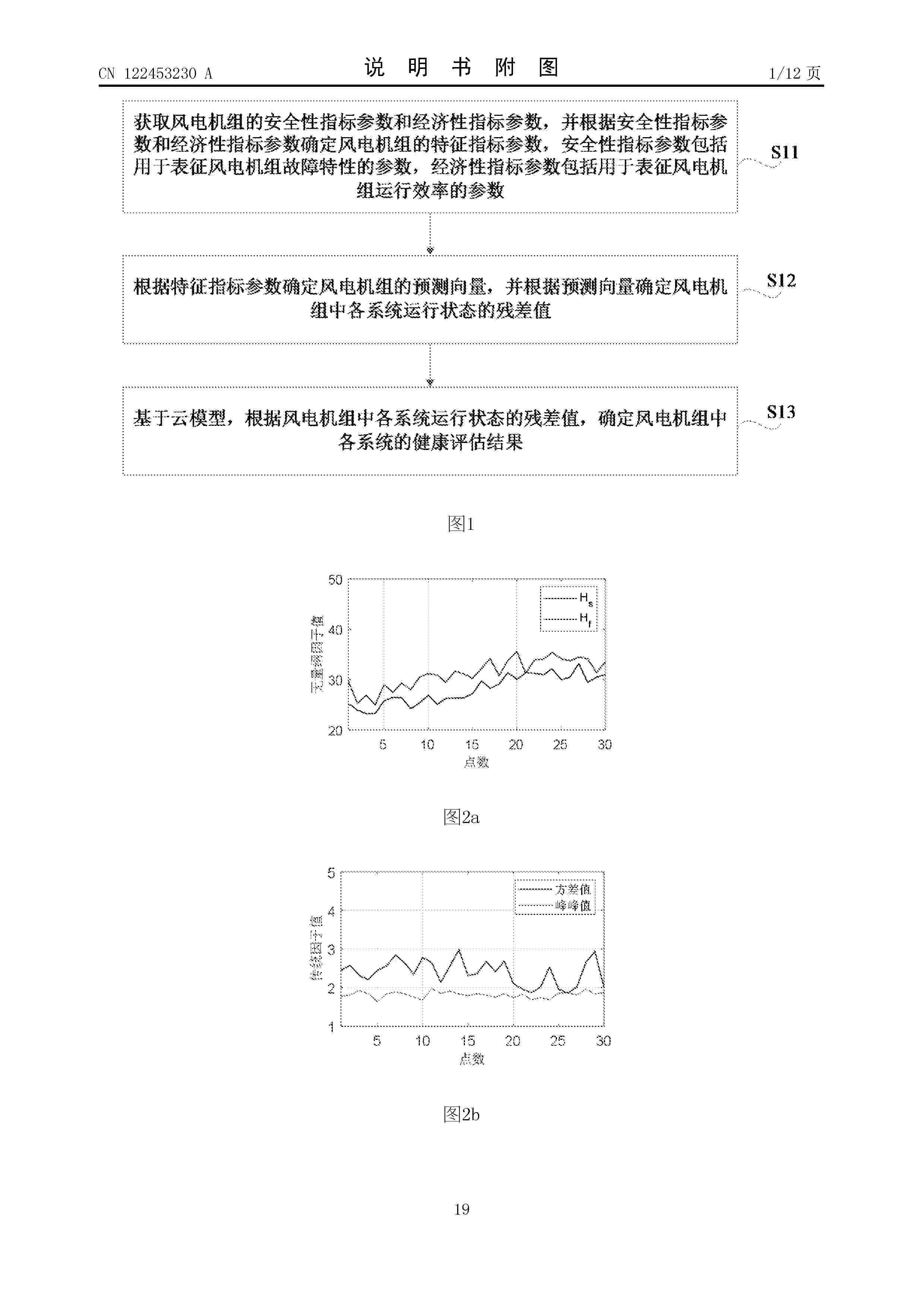
本公开涉及一种风电机组设备健康评估方法、装置、介质、设备及产品,涉及风电机组技术领域,可在保证健康评估结果准确性的同时,提高了健康评估结果的客观性。该风电机组设备健康评估方法,包括:获取风电机组的安全性指标参数和经济性指标参数,并根据安全性指标参数和经济性指标参数确定风电机组的特征指标参数,安全性指标参数包括用于表征风电机组故障特性的参数,经济性指标参数包括用于表征风电机组运行效率的参数;根据特征指标参数确定风电机组的预测向量,并根据预测向量确定风电机组中各系统运行状态的残差值;基于云模型,根据风电机组中各系统运行状态的残差值,确定风电机组中各系统的健康评估结果。

Resumen de: CN122456635A
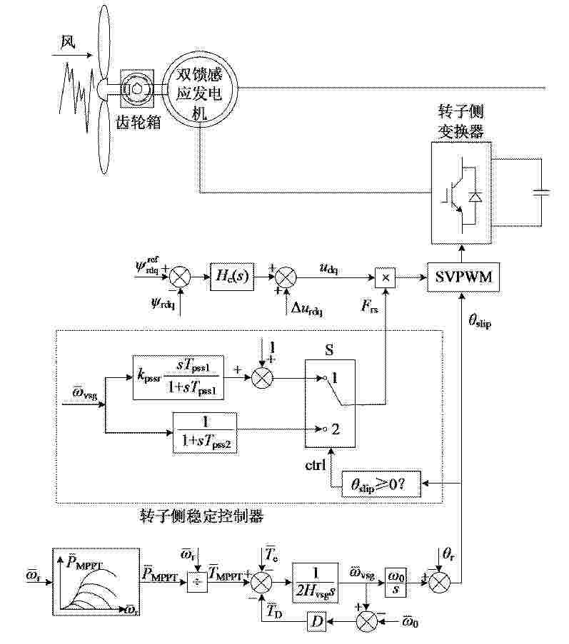
本发明涉及风电机组控制技术领域,具体涉及一种构网型双馈风电机组的控制方法及系统。针对构网型双馈风电机组不同风速下稳定裕度不同的问题,本发明在构网型双馈风电机组转子侧变换器的励磁控制环节中设置转子侧稳定控制器;根据构网型双馈风电机组实际运行的超同步工况、亚同步工况,转子侧稳定控制器分别采用低通滤波器或高通滤波器。本发明通过加入转子侧稳定控制器,有效抑制由构网型双馈风电机组转子侧变换器引起的振荡,提高构网型双馈风电机组的稳定性;同时,使定子侧、转子侧均体现出电压源外特性,增强构网型双馈风电机组主动支撑电网的能力。
Resumen de: CN122447257A
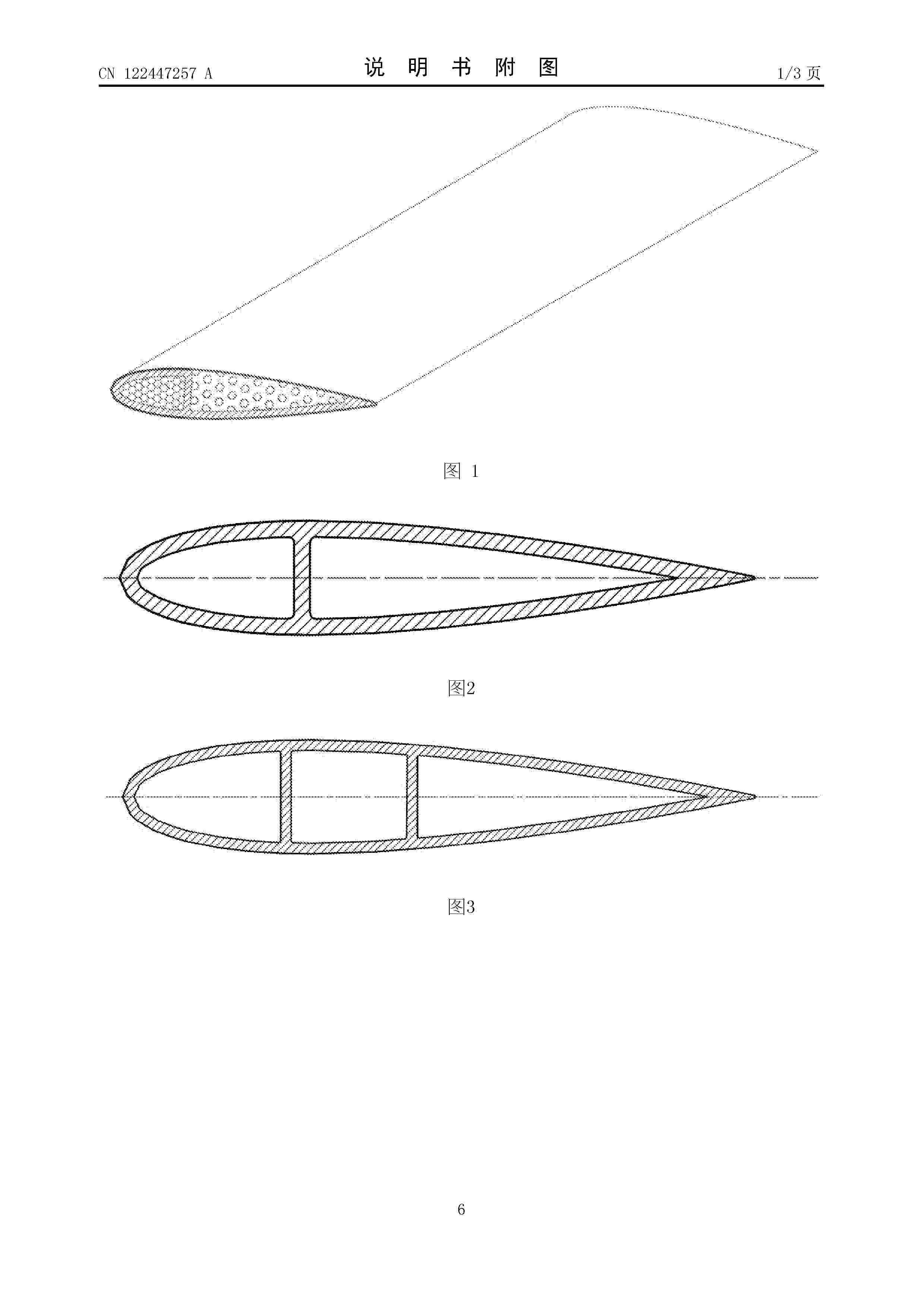
本发明涉及到H型垂直轴风力发电机叶片技术领域,尤其是指用一次拉挤型碳纤维芯材与其它碳纤维材料复合成型的H型垂直轴风力发电机的叶片结构。1、能够提高垂直轴风力机叶片的结构强度,解决垂直轴风力机叶片易疲劳断裂的问题。2、有效利用了碳纤维拉挤工艺的优势,大大提高了叶片长度方向的拉伸性能,可结合了芯材、复合材料蒙皮,提高了叶片其余方向的刚度。3、碳纤维拉挤板与碳纤维织物层压结合工艺制作叶片轮廓;所使用的芯材具有高剪切强度和压缩刚度;与其它材料合成的叶片能有效的防止屈曲并抵抗平面剪切载荷。4、H型垂直轴风力发电机的碳纤维复合材料叶片结构,除了提升叶片抗冲击力和稳定性外,重点从解决叶片重量入手,通过降低风轮重量,推进与结构作出重大改变。5、轻质碳纤维复合材料叶片和风机叶片结构,使风轮质量相较传统铝合金叶片重量降低了70‑80%,叶片重量大幅度降低,轻质高强,产品寿命周期。
Resumen de: CN224555510U
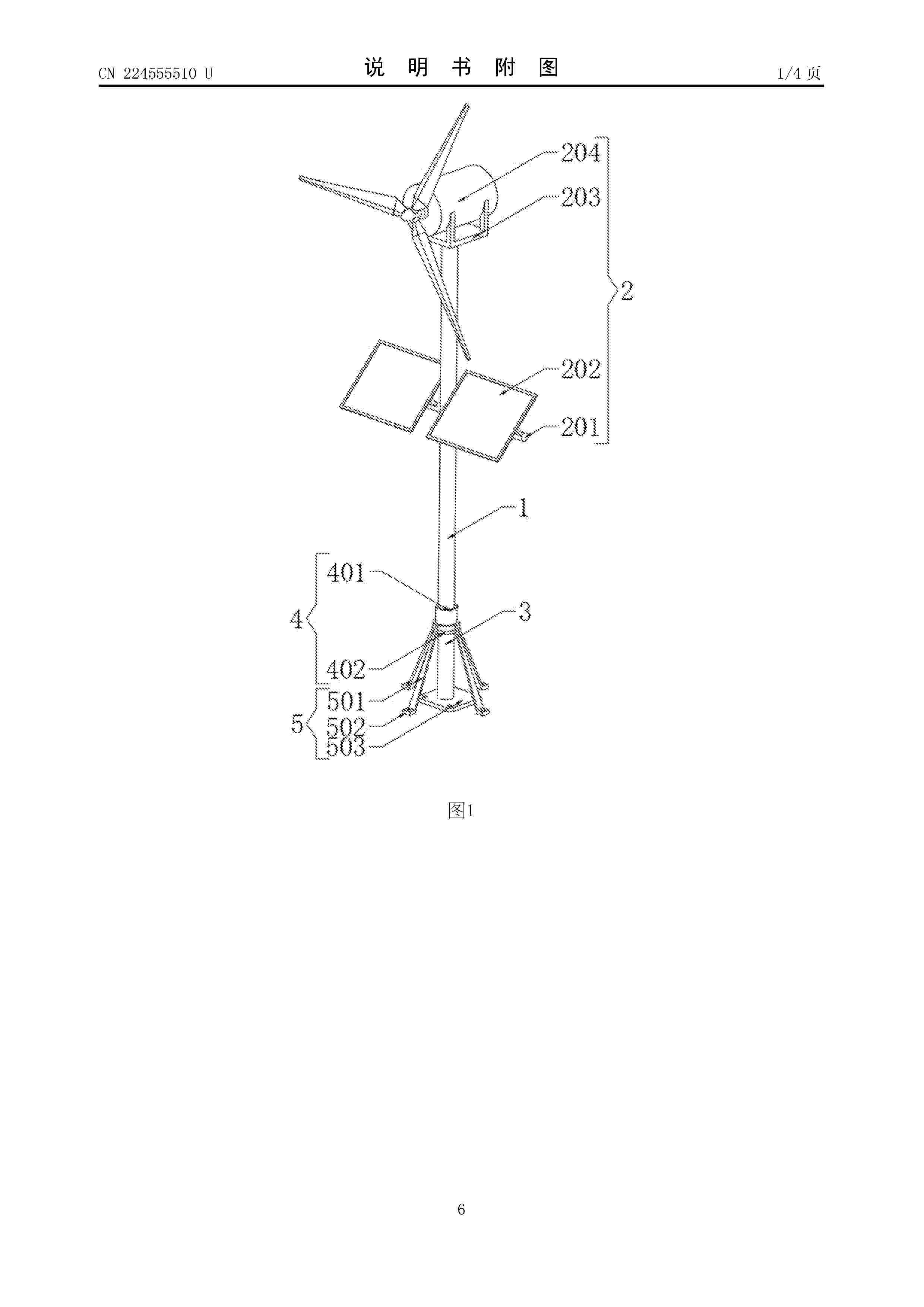
本实用新型公开了一种风光互补发电装置,包括:立杆、发电组件、固定杆、调节组件、固定组件和限制组件,发电组件设置在立杆的顶部,固定杆铰接在立杆的底部,调节组件包括螺纹套设在立杆底部的固定套环,固定套环螺纹套设在固定杆的顶部,固定杆的顶部套设有定位套环,固定组件设置在固定杆和固定套环的底部。本实用新型通过立杆、固定杆、固定套环、定位套环、固定组件和限制组件的设计,设置的固定杆与立杆之间通过铰接的方式进行连接,使得立杆得以在固定杆的顶部进行转动,设置的固定套环用于限制立杆的转动,使得在需要维护发电组件时转动立杆,调节发电组件与地面的高度,使得工作人员无法登高即可完成维护。
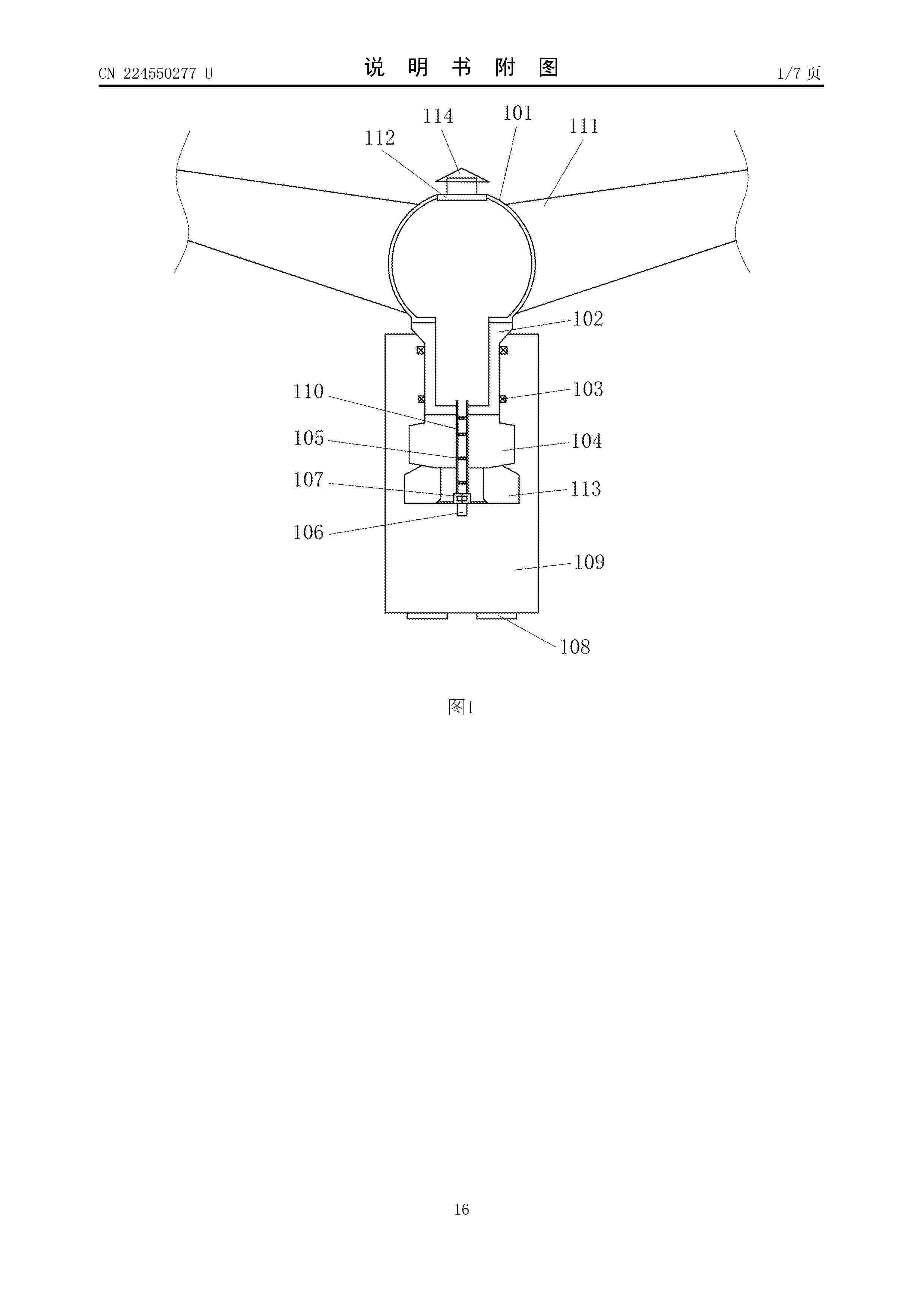
Resumen de: CN224550277U
本公开提供一种齿轮箱、传动系统、风力发电机组及其散热系统,所述齿轮箱包括箱体、输入轴以及空心管,所述输入轴为空心轴且可转动地设置于所述箱体的第一侧,所述空心管的第一端设置在所述输入轴中且第二端沿着所述输入轴的轴线向所述箱体的与所述第一侧相对的第二侧延伸,所述空心管的两端分别贯穿所述第一侧和所述第二侧并形成为贯穿所述箱体的通风道,使得箱体两侧的气流可以通过空心管连通,从而使得轮毂和机舱罩气流连通成为可能,将用于驱动气流流动的气流发生器设置在机舱罩内,而无需在轮毂内设置气流发生器,从而降低了轮毂内气流发生器掉落的风险,提高了轮毂的散热可靠性。
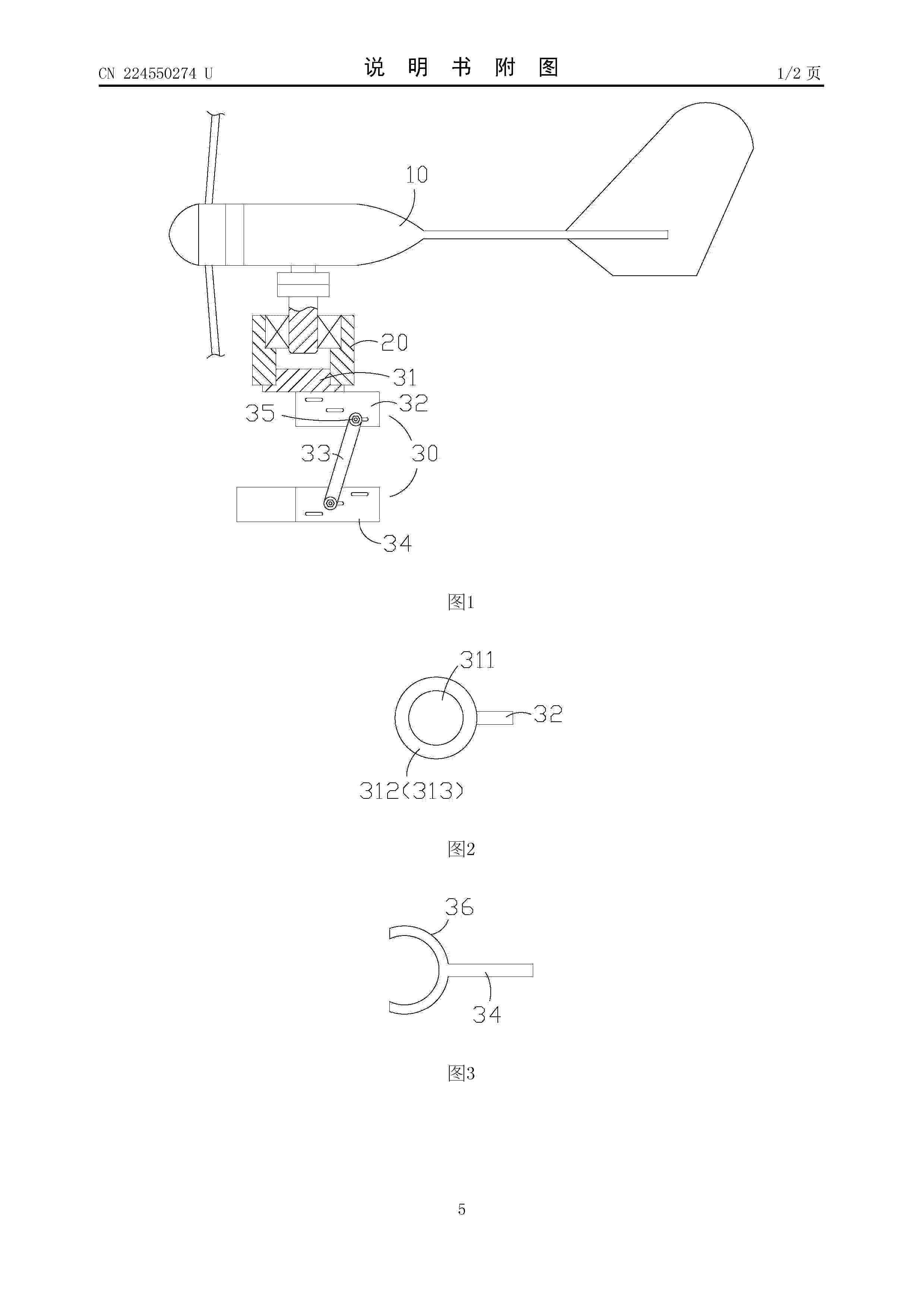
Resumen de: CN224550274U
本实用新型涉及一种路灯小型风力发电器,其包括风力发电器、接驳管体以及固定器,其中,该风力发电器包括底部插接轴,该底部插接轴设置在该风力发电器底部,该接驳管体具有上轴承腔以及下插接腔,其中,该上轴承腔中设置有轴承,该底部插接轴插设在该轴承中,该固定器插设在该接驳管体的该下插接腔中,该固定器包括顶盘、上调位板、装配杆以及下调位板,其中,该顶盘包括凸台体以及限位盘,该凸台体可拆卸的插接在该接驳管体的该下插接腔中,该上调位板固定连接在该限位盘底部,该上调位板上设置有数个上档孔槽,该装配杆具有上螺栓孔、下螺栓孔以及杆体,该下调位板上设置有数个下档孔槽,该下调位板前端设置有连接焊爪。
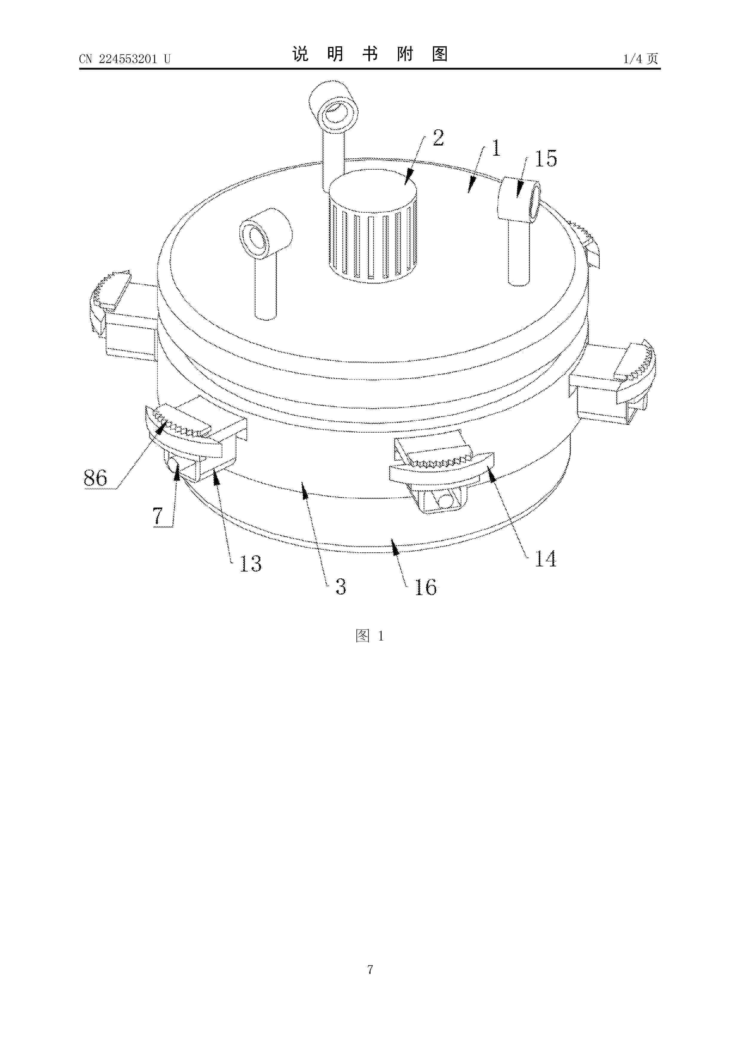
Resumen de: CN224553201U
本实用新型属于检测装置技术领域,具体的说是一种风电塔筒裂隙检测装置,包括顶板,顶板的顶部固定连接有第一电机,第一电机的输出端贯穿顶板并固定连接有调节板。本实用新型通过调节机构的设置,配合支撑板和超声波检测仪,在风电塔筒内逐渐吊起上升,启动第二电机,支撑板带动其顶部的破损刀片和底部的超声波检测仪移动并逐渐靠近风电塔筒的内壁,启动第一电机带动调节板和破碎刀片高速转动,对附着在风电塔体内壁的冰块进行粉碎,启动加热块对抵接块加热,对风电塔筒内壁残余的碎冰进行融化,到达检测位置,探头对准检测位置,停止第一电机,启动电动伸缩杆带动该探头抵接风电塔筒的内壁进行超声波检测。
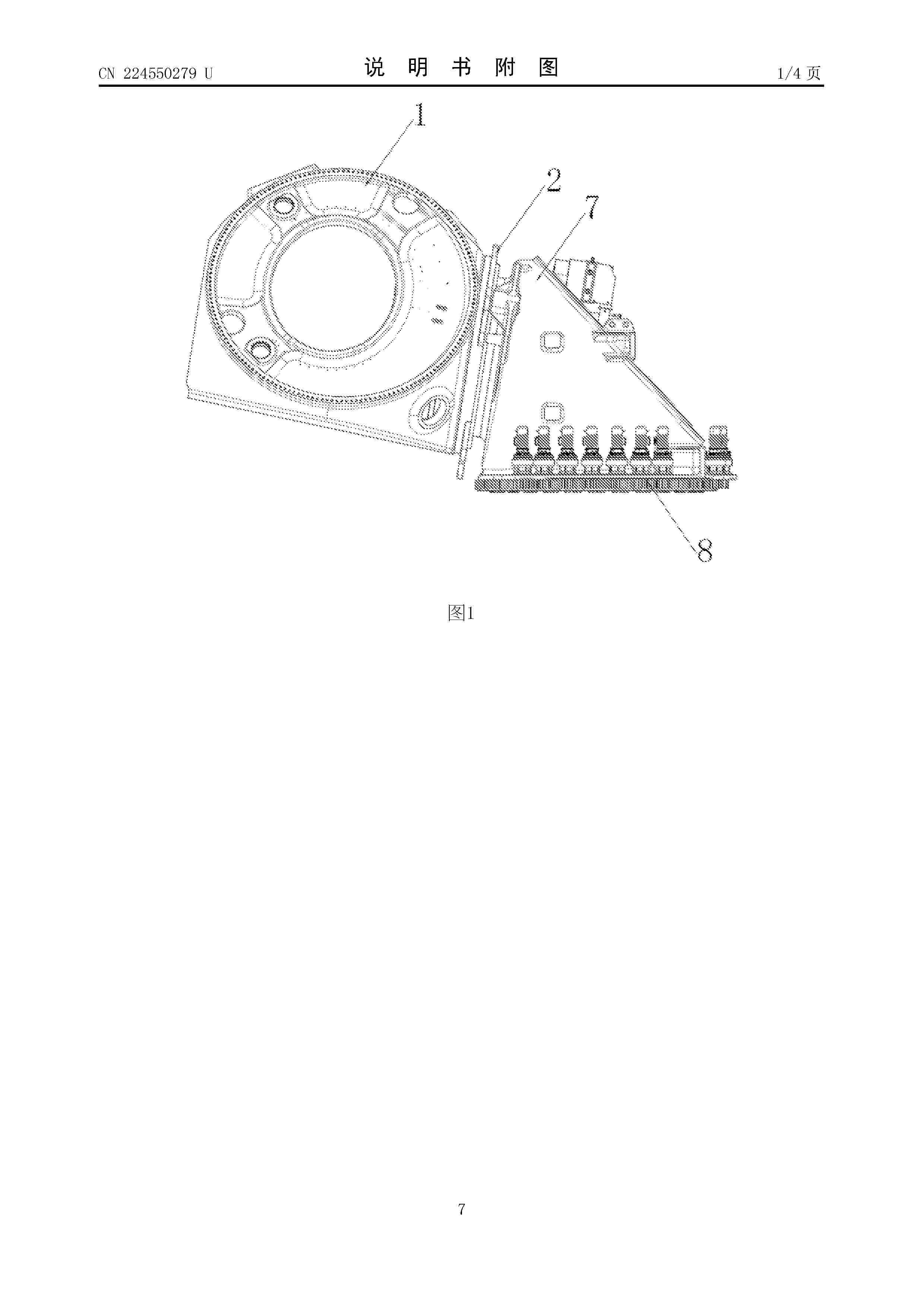
Resumen de: CN224550279U
本实用新型公开了一种与轮毂集成的紧凑型半直驱传动系统结构,包括轮毂本体、主轴承组件、主轴、齿轮箱、发电机、隔板法兰和机舱底座,轮毂本体的机舱侧设置有用于安装主轴承组件的主轴承安装位,主轴承组件安装于主轴承安装位,其外圈与轮毂本体连接,其内圈套设于主轴上,齿轮箱的前部设置于轮毂本体内部,其后部设置于机舱底座内部,且其前端通过隔板法兰与轮毂本体连接,齿轮箱的中部与主轴的前端连接,机舱底座的前端与主轴的后端连接,发电机设置于机舱底座的内部,与齿轮箱集成安装到一起。本实用新型基于主轴承将轮毂和齿轮箱集成安装到一起,组成紧凑型集成传动系统结构,大大缩短了传动系统轴向长度,使得机组主机体积更小,重量更轻。
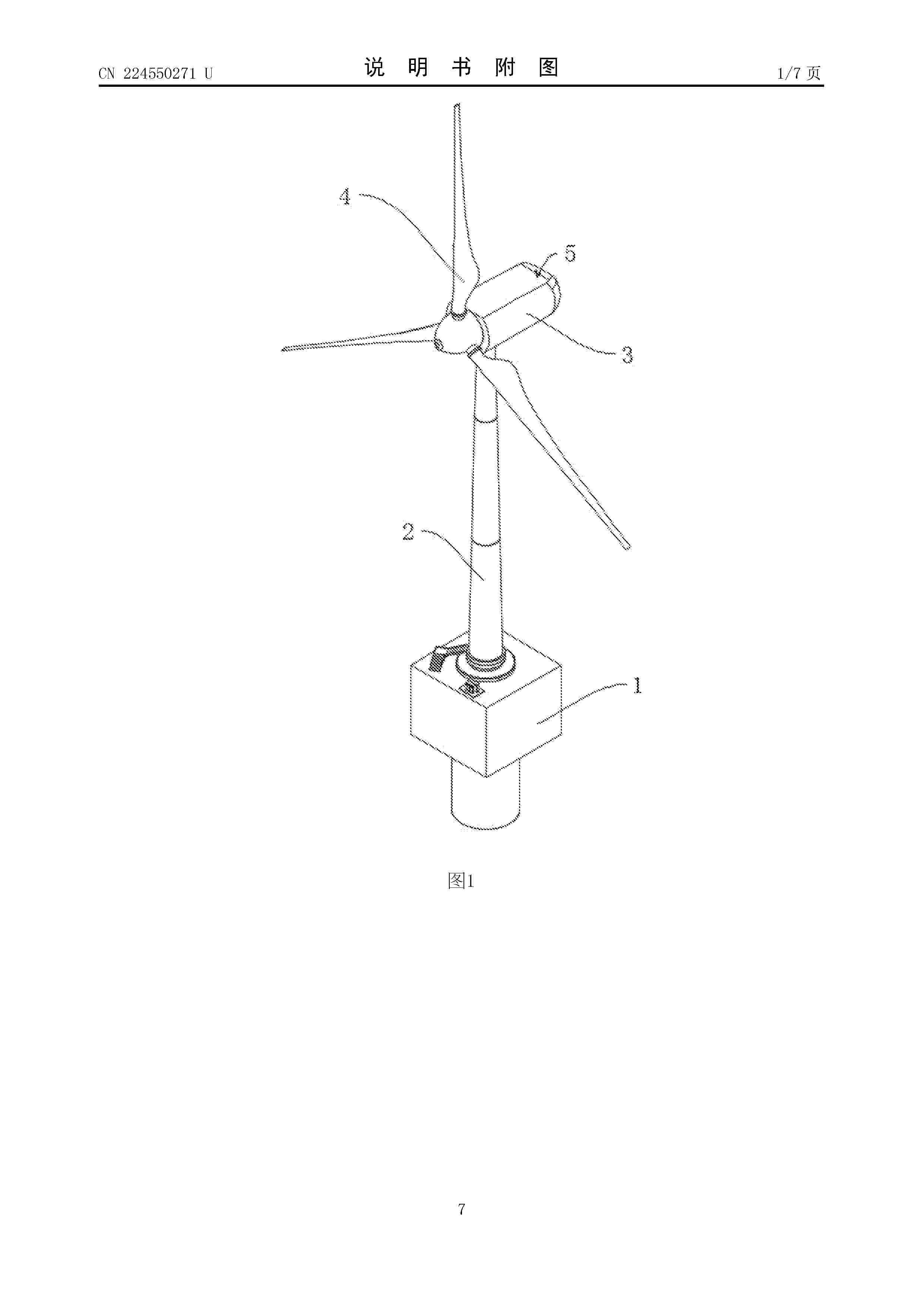
Resumen de: CN224550271U
本实用新型涉及风力发电技术领域,公开了一种海上风力发电设备,包括塔筒、主机外壳和叶片,所述塔筒顶端转动设有主机外壳,所述主机外壳一端转动设有叶片,所述塔筒顶部外壁设有固定齿圈,所述主机外壳底部设有齿轮,所述齿轮能够与固定齿圈相啮合,所述主机外壳内部设有伺服电机,所述主机外壳底部两侧固定有电动液压杆,本实用新型启动伺服电机带动齿轮转动,从而带动主机外壳和叶片绕着塔筒顶端进行转动,使得叶片偏离主风向15°‑20°减少风力输入,避免叶片被强风直吹造成损伤,在角度调节完成后,通过电动液压杆活塞杆伸出,通过夹板与电动液压杆的横向滑动连接,能够让固定齿卡在固定齿圈的齿之间,保证主机外壳的角度稳定。
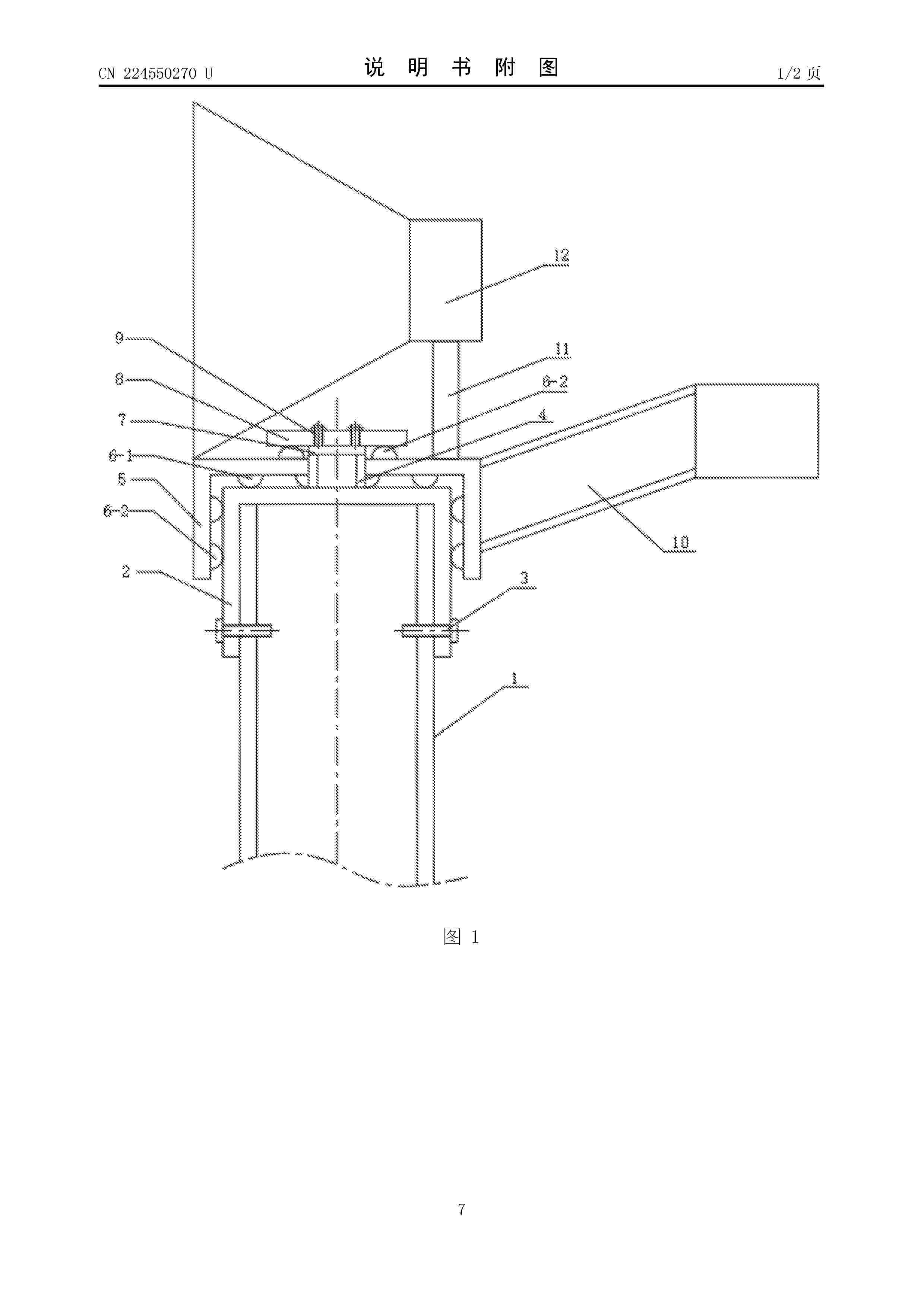
Resumen de: CN224550270U
本实用新型具体涉及风力发电技术领域,具体涉及一种聚风罩自动导风装置;具体的,本申请设置有:固定于套筒顶面的套筒中心轴;旋转罩嵌套于套筒,且旋转罩基于第一万向球/第二万向球活动式接触于套筒的顶面/外侧面;聚风罩固定于旋转罩顶面,条形尾翼固定于旋转罩外侧面;在满足“条形尾翼的延伸方向与聚风罩的迎风面相反”的条件下,当风向发生明显变化时,风力带动条形尾翼的转动,以此同时,旋转罩在第一万向球及第二万向球的滚动作用下,进行对应的转动,直至聚风罩的迎风面朝向“风吹来的方向”,以实现:结合外界实时风向,对聚风罩迎风面进行调节,以提高风力发电效率。
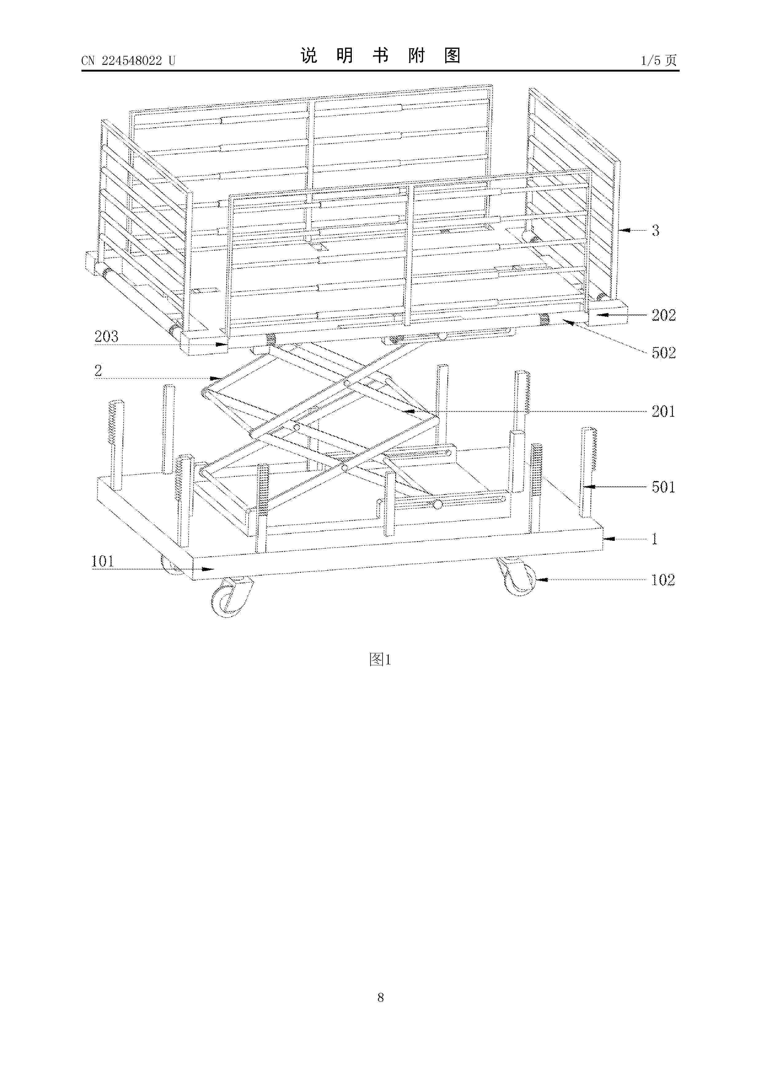
Resumen de: CN224548022U
本实用新型公开了一种风力发电塔筒维修平台,涉及维修平台技术领域。本实用新型包括:移动平台;升降平台,升降平台固定在移动平台的上侧;四个护栏机构,四个护栏机构安装在升降平台的周侧,护栏机构包括定位组件、翻转组件和护栏组件,定位组件装设在升降平台上;其中,翻转组件包括两个齿板和一个转杆,两个齿板均固定在移动平台的上侧,转杆通过扭簧转动配合在升降平台的一侧,齿板与转杆相互啮合。本实用新型通过在移动平台的底板下侧设置的多个移动轮,维修人员可轻松推动平台移动至塔筒附近,无需人力搬运,提升维修前期准备效率;同时可通过电动轮驱动进一步减少操作麻烦,适配不同场地移动需求。
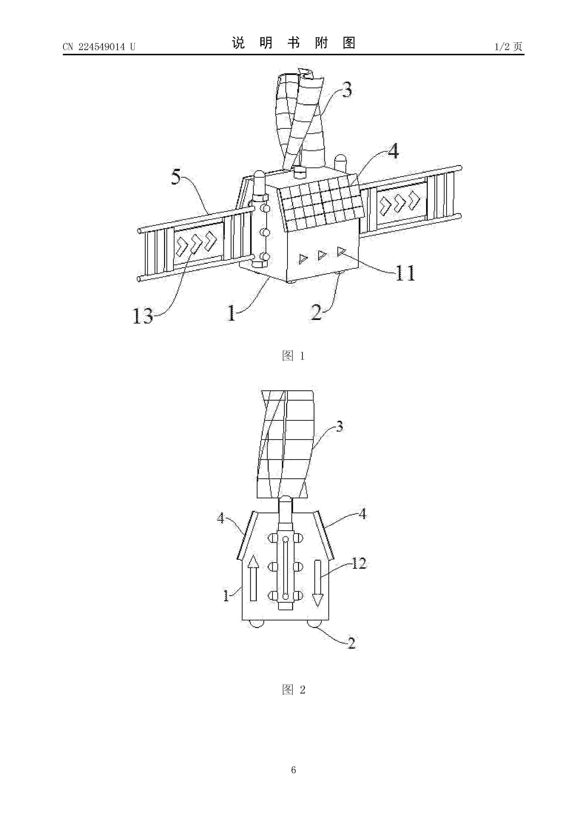
Resumen de: CN224549014U
一种可变车道机器人及移动护栏,包括主机身,主机身底部装设滚轮,主机身内部具有驱动滚轮行走的电控单元,在主机身顶部装设有风机、侧面装设太阳能电池板,所述主机身内部具有储能单元用于存储风机和太阳能电池板转化电能。本实用新型提出的可变车道机器人以及移动护栏,可以利用太阳能并可以捕获车流风能发电供能,节能减排效果显著,部署便利,配合其储能单元,可以实现完全清洁能源供电。
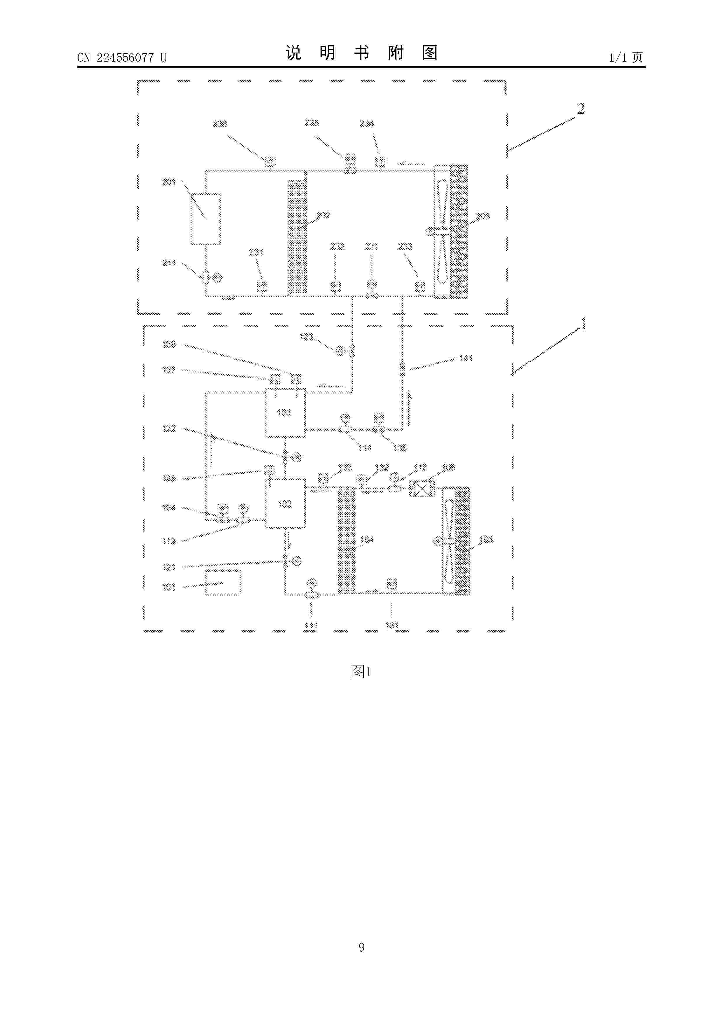
Resumen de: CN224556077U
本实用新型公开了一种基于差温介质动态置换法的增效降温装置,其包括增效降温支路系统和机组原散热系统,其中:增效降温支路系统包括集中控制器、低温介质罐、差温交流罐、后端换热器、后端散热器、物冷压缩机、低温介质循环泵、物冷循环泵、差温介质循环泵、增效换热泵、低温介质阀、罐间节流阀、增效换热阀、前端物冷温度传感器、后端物冷温度传感器、后端低温介质温度传感器、差温介质循环流量传感器、低温介质罐温度传感器、增效换热泵流量传感器、差温交流罐液位传感器、差温交流罐温度传感器以及增效止回阀,机组原散热系统包括原机组设备、原机组换热器、原机组散热器以及原机组循环泵等。
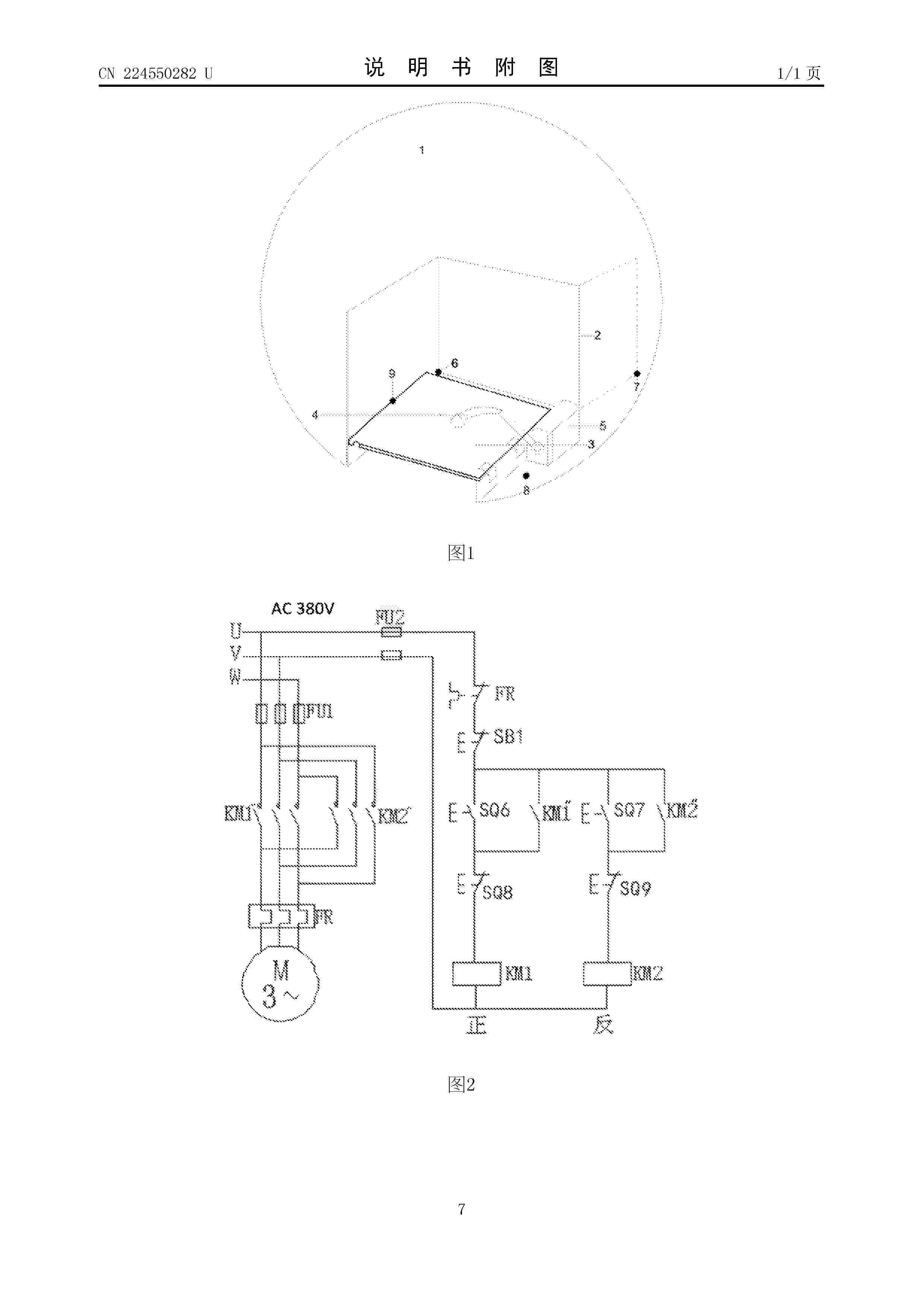
Resumen de: CN224550282U
本实用新型公开了一种用于风力发电机组吊物孔的安全连锁装置,涉及风电机组技术领域,其包括吊物孔围栏、吊物孔盖板、驱动组件和行程开关组件,该吊物孔围栏、吊物孔盖板、驱动组件、行程开关组件都设于机舱平台内;吊物孔盖板装配在吊物孔位置,吊物孔围栏安装在吊物孔外围,通过驱动组件、行程开关组件、吊物孔围栏的动作控制吊物孔盖板在吊物孔位置的开合状态。本实用新型通过该装置的自动触发操作,有效预防因误操作引发的人员坠落事故,切实保障作业人员人身安全,提高了施工安全性。
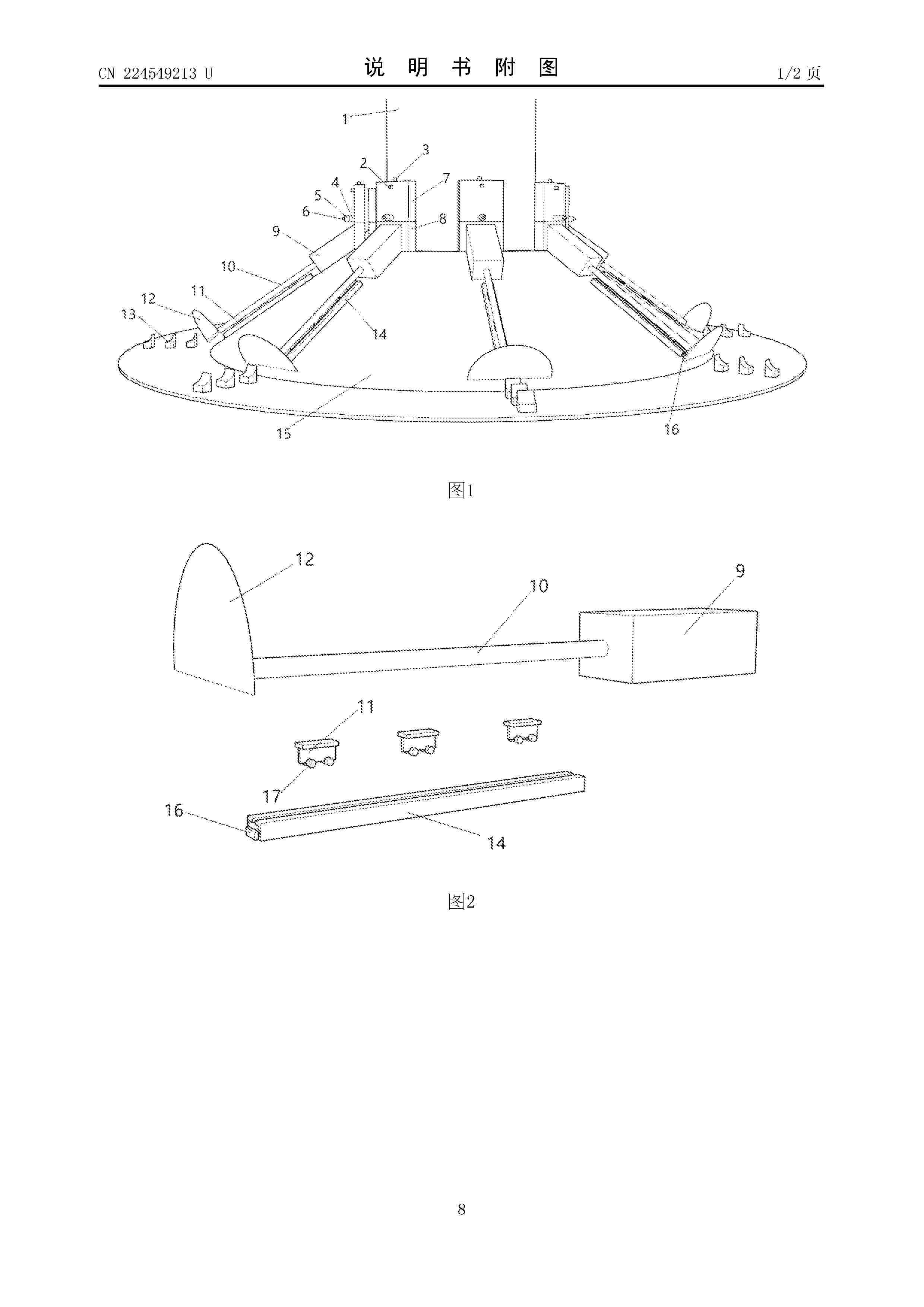
Resumen de: CN224549213U
本实用新型涉及海上风电工程技术领域,尤其涉及一种海上风电防冲刷装置,包括海风桩基、储能组件和喷水组件,所述储能组件用于将水流能量转换为电能,所述喷水组件与储能组件连接,所述喷水组件朝向水流方向喷水;所述储能组件和喷水组件设有多组并环绕海风桩基设置;通过将海风桩基周围潮流、波浪的机械能转化为电能,再将电能转化为与潮流、波浪反向的水流进行消能,设计巧妙,具有较强的工程可实施性。
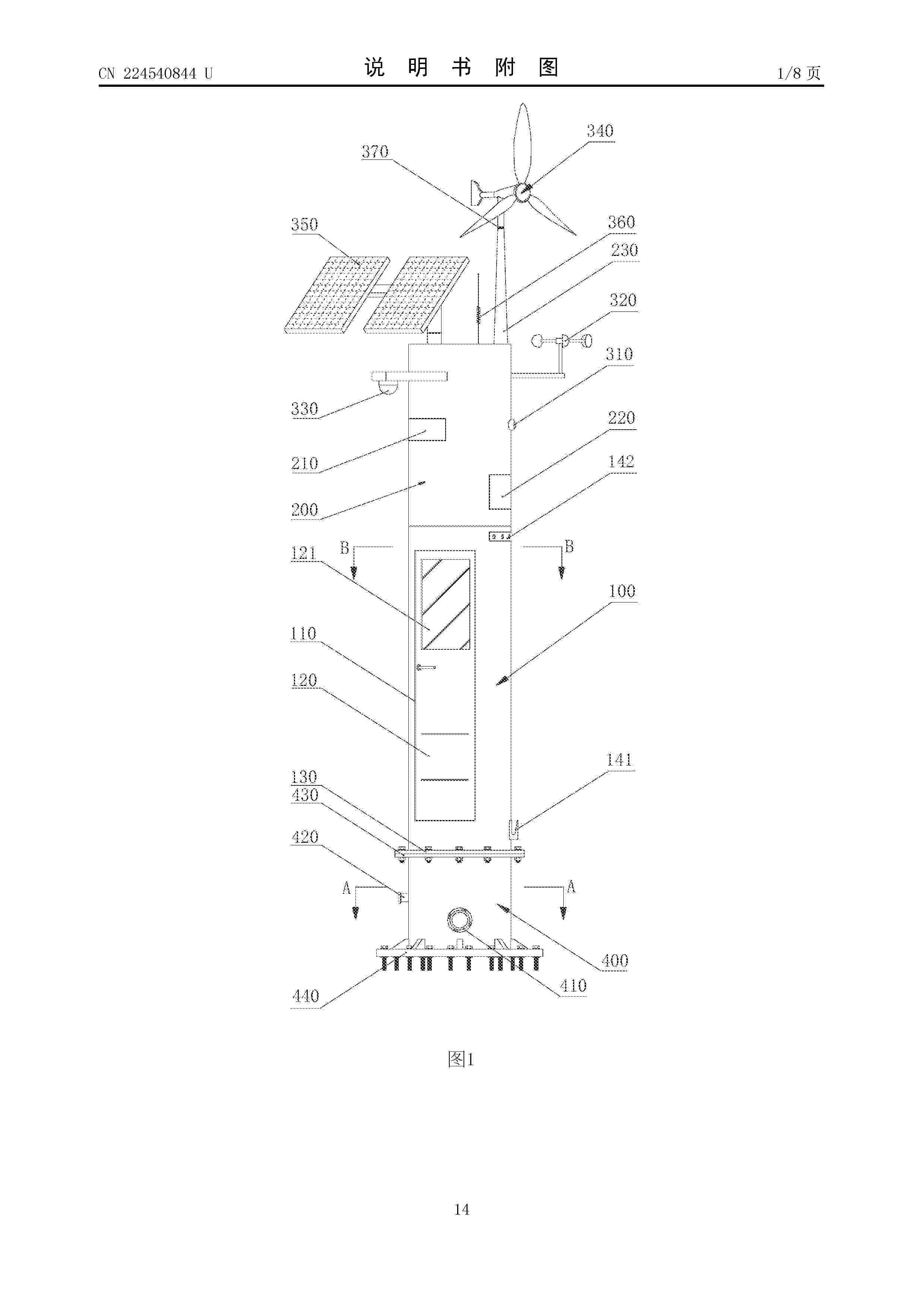
Resumen de: CN224540844U
本实用新型提供了一种多功能消防柜,包括第一柜体、与之连接的第二柜体,及发电装置与储能装置;第一柜体内设有支撑柱及套筒,套筒套在支撑柱上,以及与套筒固定连接的若干用于固定或悬挂消防器材的隔板/挂板,隔板/挂板垂直或平行于套筒的轴线设置,第一柜体设门洞,并设门扇对门洞开合;第一柜体下端设第一法兰底座,用于通过螺栓对外固定连接;发电装置设在第二柜体上,储能装置设于第二柜体内用于存储发电装置输出的电能;第一柜体为圆筒状、椭圆筒状或多棱筒状中的任意一种。如此设置,无需铺设大面积硬化地面和消防电缆,只需要一小块硬地面、石头或埋桩就能实现安装,简单、方便、造价低,能适应不通路、不通电的深山及林地安装使用。
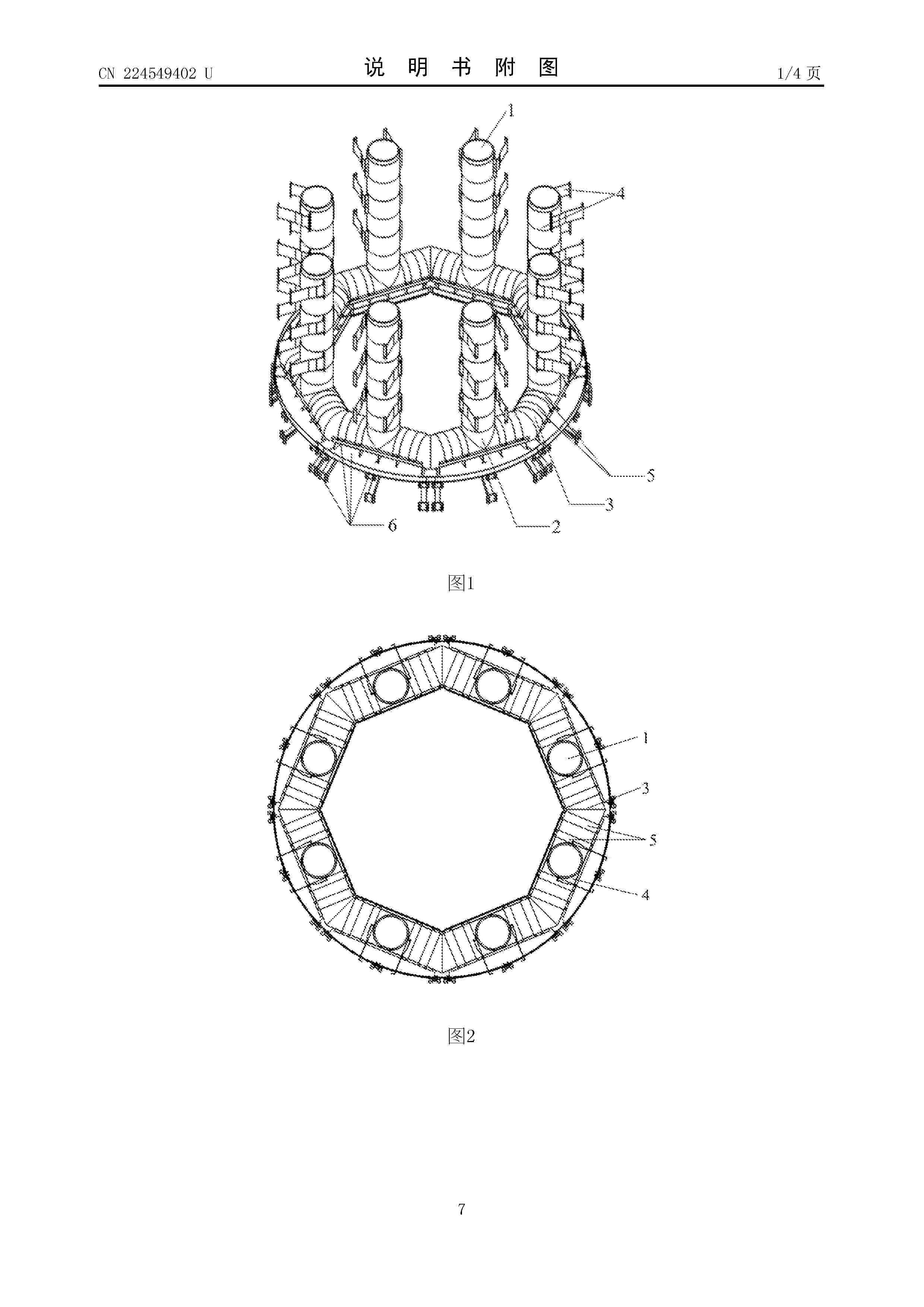
Resumen de: CN224549402U
本实用新型涉及阻尼器领域,具体涉及一种适用于风电支撑结构的多立柱环形调谐液柱阻尼器,包括若干阻尼机构,每个阻尼机构均包括竖管立柱、竖管支撑单元、T形三通、弯折管和底部支撑单元,T形三通包括主管和支管,竖管立柱与支管连通且竖管立柱通过竖管支撑单元与塔筒内壁固定连接,弯折管两端分别与相邻两个T形三通的主管连通形成环形流道且弯折管与主管通过底部支撑单元与塔筒内壁固定连接,竖管立柱、T形三通和弯折管内填充有工作介质;采用本技术方案,以实现水平多向的有效减振。
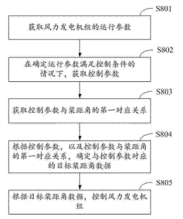
Resumen de: CN119641549A
The invention discloses a control method and device of a wind generating set and a program product. In the method, operation parameters of the wind generating set are obtained; under the condition that the operation parameters meet the control conditions, it is determined that the wind generating set is in the grid-connected rotating speed control stage, the control parameters are obtained, and the first corresponding relation between the control parameters and the pitch angle is obtained; determining target pitch angle data corresponding to the control parameters according to the control parameters and the first corresponding relation between the control parameters and the pitch angles. The determined target pitch angle data is the pitch angle data when the wind generating set achieves the better output power in the current operation state. And controlling the wind generating set according to the target pitch angle data. Therefore, in the grid-connected rotating speed control stage, the pitch angle of the wind generating set is optimized according to the control parameters, so that the output power of the wind generating set is improved, and the generating capacity of the wind generating set is improved at a low wind speed.
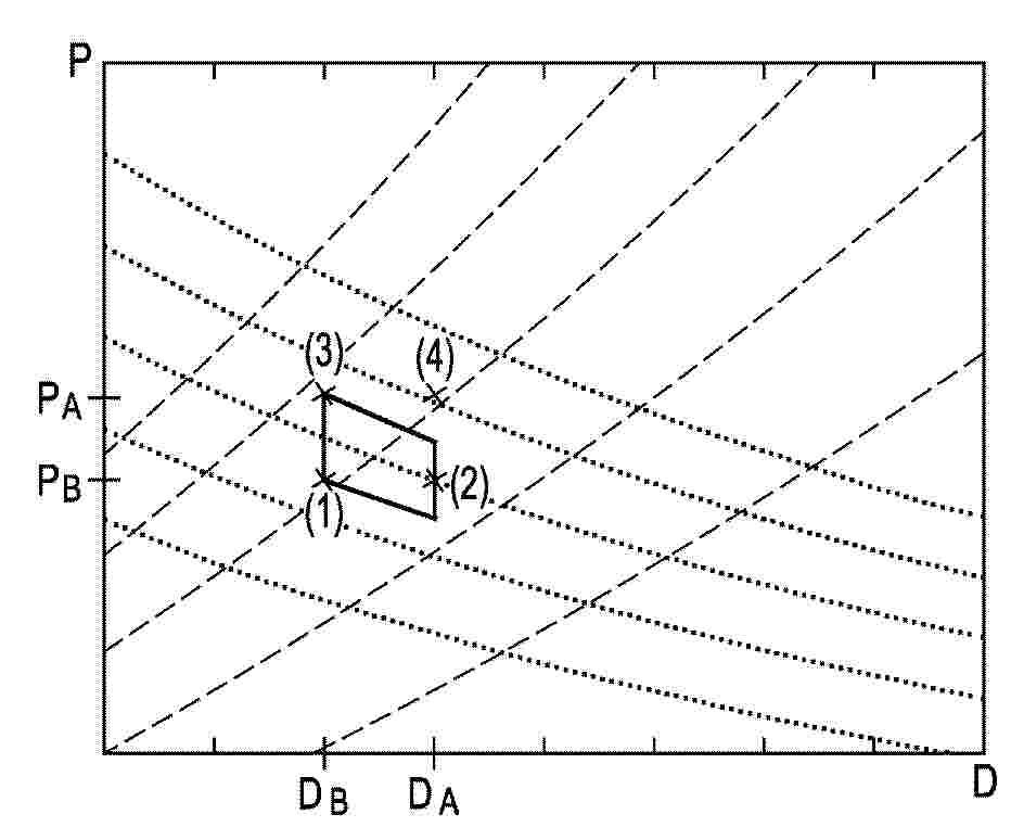
Resumen de: WO2025149330A1
The invention relates to a method for providing an adapted design for an adapted generator (1) for a wind turbine with an adapted power variable (DA; PA). The method comprises the steps of providing (II) an existing design for an existing generator (1) for a wind turbine with an existing power variable (DB; PB); comparing (III) the adapted power variable (DA; PA) with the existing power variable (DB; PB); and adapting (V) a winding (10) of a stator (2) of the generator (1) on the basis of the comparison.
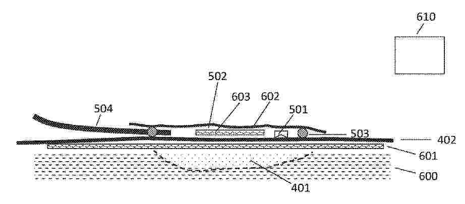
Resumen de: WO2025140762A1
The invention relates to method repairing defect regions (401) which have developed during manufacturing of a wind turbine blade component (599). The method involves the steps of preparing a layered fiber material structure (600) for the wind turbine blade component; arranging a vacuum bag (402) over the layered fiber material structure; applying a vacuum assisted resin infusion process; recognizing a defect region below the vacuum bag which has not been sufficiently infused with resin; placing a piercing device on the vacuum bag; sealing an area covering the piercing device (501) and at least a part of the defect region with a repair bag (502) so that the repair bag forms an airtight envelope over the piercing device; piercing the vacuum bag with the piercing device; and extracting air out of the repair bag to force the resin from locations surrounding the defect region to flow into the insufficiently resin infused part of the layered fiber material structure.
Resumen de: WO2025140763A1
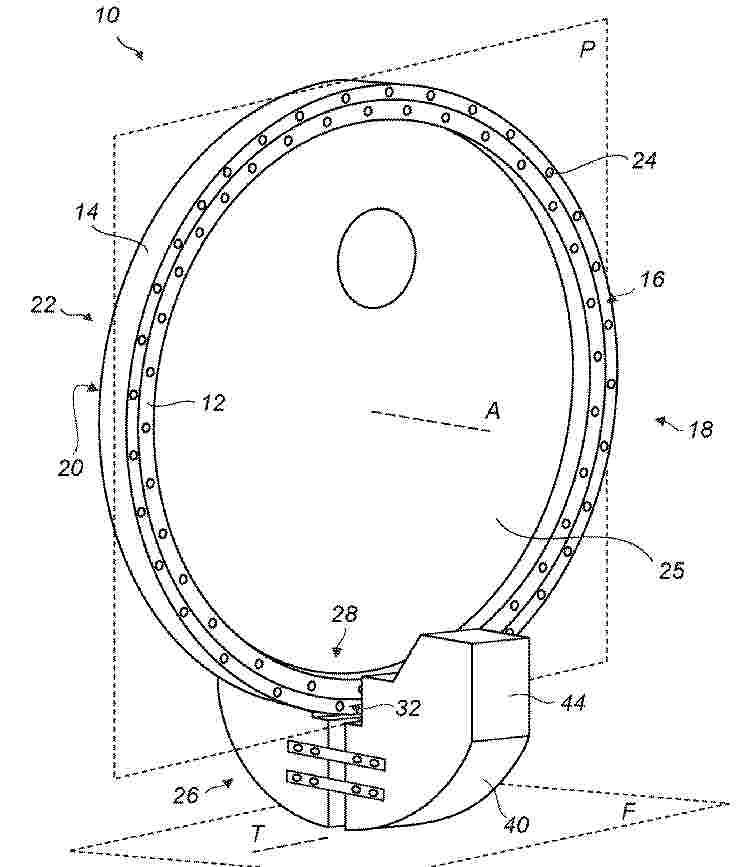
In a first aspect of the present invention there is provided turnover support apparatus for supporting a wind turbine bearing when turning the bearing in an assembly process. The wind turbine bearing comprises an inner bearing ring configured for attachment to a first wind turbine component and an outer bearing ring configured for attachment to a second wind turbine component. The inner and outer bearing rings are rotatable relative to one another about a bearing axis and in a bearing plane orthogonal to the bearing axis. The turnover support apparatus comprises a bearing cradle configured for attachment to the wind turbine bearing to assist turning the bearing about an axis orthogonal to the bearing axis. The bearing cradle comprises a bearing holding portion on a first side of the cradle. The bearing holding portion comprises an aperture for receiving at least a portion of the outer bearing ring and fixing means for releasably fixing at least one of the inner and/or outer bearing ring to the cradle. The bearing cradle further comprises a curved rocking surface on a second side of the bearing cradle opposite to the first side of the cradle such that, in use, the wind turbine bearing may be supported by the bearing cradle on an underlying floor surface via the curved rocking surface. The curved rocking surface is configured to define a turnover axis at a point of contact between the curved rocking surface and the floor surface about which the cradle and attached bearing are p
Resumen de: WO2025131200A1
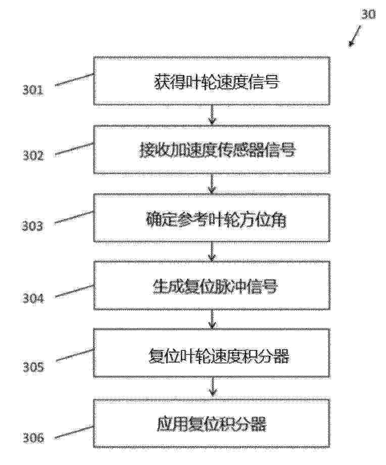
The invention relates to determining rotor azimuth angle of a wind turbine. The invention involves obtaining a rotor speed signal indicative of rotor speed of the wind turbine. The rotor speed signal is for input into a rotor speed integrator. The invention involves receiving an acceleration sensor signal, from an acceleration sensor located in a rotor hub of the wind turbine, indicative of gravitational acceleration of the rotor hub relative to a rotation axis of the rotor hub. The invention involves determining a reference rotor azimuth angle based on the received acceleration sensor signal, and generating a reset pulse signal based on the determined reference rotor azimuth angle. Upon receiving the generated reset pulse signal at the rotor speed integrator, the integrator is reset. The invention involves using the reset rotor speed integrator to determine wind turbine rotor azimuth angle based on the obtained rotor speed signal.
Resumen de: WO2025131723A1
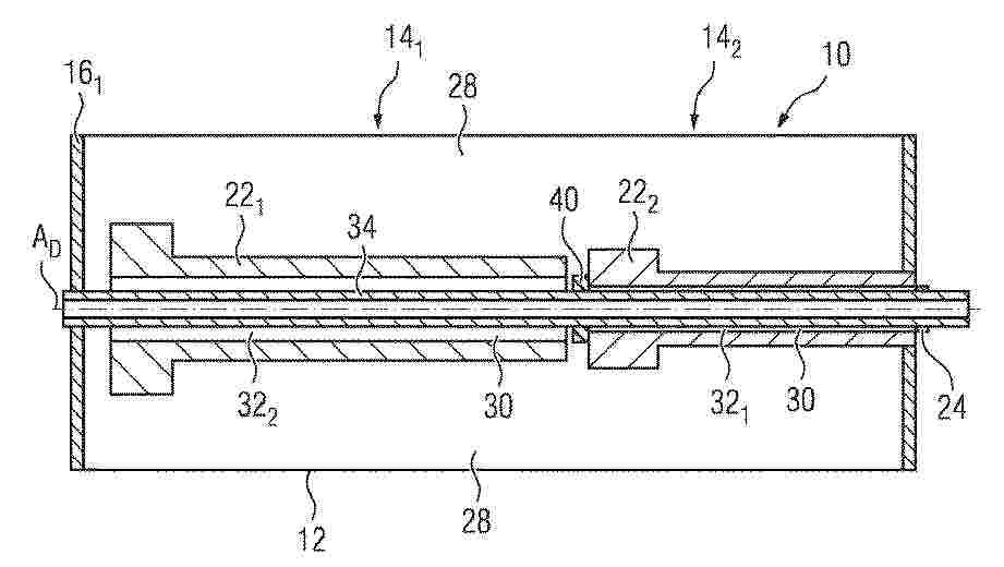
The invention relates to a planetary gearing (10) for a wind turbine (70) driven by means of a rotor (72), comprising: a gearing housing (12) which surrounds an oil-accommodating space (28) for accommodating an oil volume; a plurality of planetary stages (141, 142) which revolve around an axis of rotation AD and which are connected to one another in terms of driving; a pitch tube (34) which is disposed coaxially inside the two planetary stages (141, 142) and which is rotationally rigidly connected to a planet carrier (161) of the first planetary stage (141), wherein the pitch tube (34) is sealed with respect to an exterior of the gearing housing (12) and a volume region (30) is formed between the pitch tube (34) and each of the planetary stages (141, 142). At least a portion (32) of the volume region (30) is sealed with respect to the oil-accommodating space (28). A complex, expensive and fault-prone oil discharge device is rendered unnecessary. In the sealed volume region (30), the pitch tube (34) no longer has any contact with the oil.
Resumen de: GB2636112A
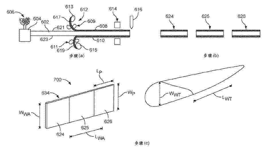
A wind turbine blade shell (100, fig.1) with a shear web assembly 344, that typically runs from the blade root to the blade tip. The assembly has multiple sandwich panels 324, connected to one another at lateral edges 336, 338, to form a series of sandwich panels. Along the top 350 and bottom 352 edges of the series of sandwich panels there are top 348 and bottom 354 connectors. In the upper and lower portions of the blade shell, upper and lower connectors extend lengthways on corresponding upper 316 or lower 320 spar caps. The length of the series of sandwich panels matches the length of the wind turbine blade shell and is aligned longitudinally. The top connector is in the upper connector on the upper spar cap and the bottom connector is in the lower connector of the lower spar cap. The connectors on the assembly may have concave profiles to correspond with convex profile connectors on the spar caps. There may be channels for adhesive to join the assembly to the connector. A method of manufacture on site and installation is also included.
Nº publicación: CN224548571U 24/07/2026
Solicitante:
海南海马汽车有限公司海马汽车有限公司
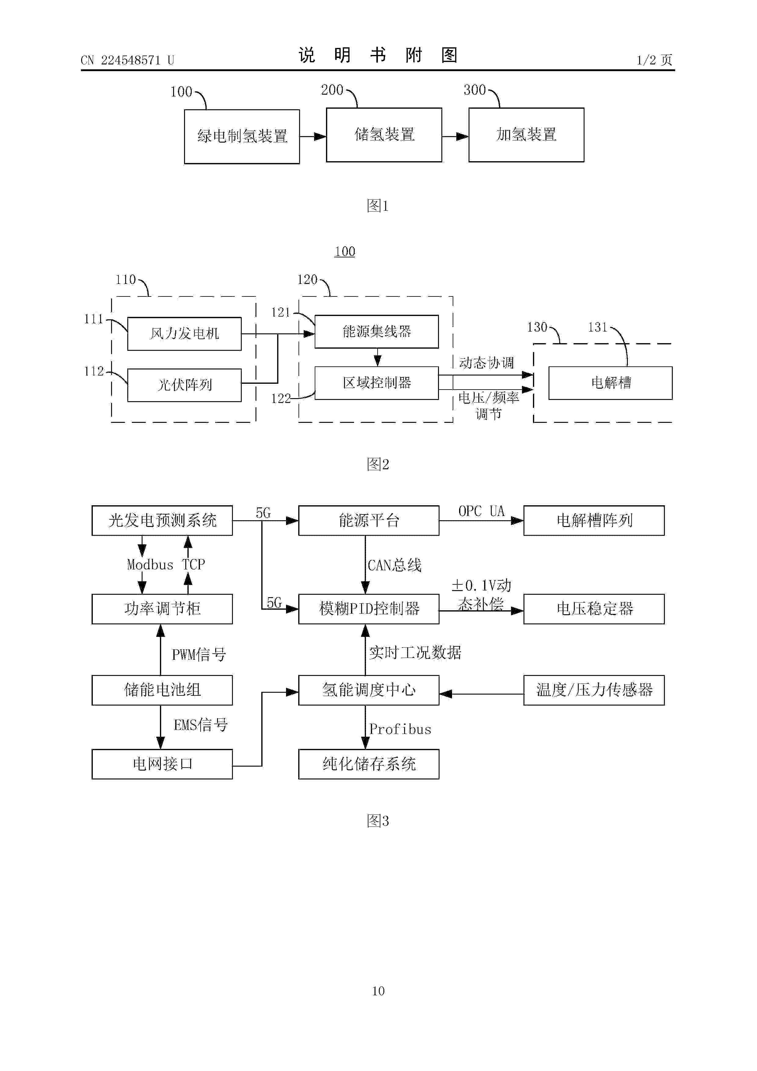
Resumen de: CN224548571U
本实用新型提供了一种绿电制氢、储氢及加氢一体化系统,涉及氢能技术领域,包括:绿电制氢装置、储氢装置和加氢装置,绿电制氢装置包括可再生能源发电器件、调控器件以及制氢器件,调控器件用于将可再生能源发电器件产生的电力进行整流稳压后输出至制氢器件进行制氢;储氢装置与制氢器件相连,并用于将制氢器件产生的氢气进行压缩储存;加氢装置与储氢装置相连,并用于将储氢装置内储存的氢气对车辆进行加注。如此在可再生能源发电器件、调控器件和制氢器件的配合下,实现将制氢、储氢和加氢结合形成一体化的设计,相比现有技术的子母站设计方式,占地面积更小,所耗成本更低。
 BOPI
BOPI
 Sede Electrónica