Si deseas distinguir tus productos, servicios o ambos de los de otra empresa, es posible que necesites una marca o nombre comercial. Descubre qué son, en qué consiste su procedimiento de registro y qué implica.

Información sobre los plazos de presentación de solicitudes de transformación de marcas de la Unión Europea en marca nacional española. Más información


Si tienes un nuevo dispositivo, producto o procedimiento que resuelva un problema técnico o tenga una ventaja práctica, existen distintas formas de protegerlo en España y en otros países. Descubre cómo hacerlo.

¿Tu innovación reside en la estética, la ornamentación o la apariencia de tu producto? Protégela mediante un diseño industrial. Descubre qué derechos confiere el registro y cómo realizar la tramitación.

Las indicaciones geográficas protegen el nombre de un producto originario de una zona geográfica, a la cual le debe una determinada calidad, reputación u otra característica. Descubre qué son, en qué consiste su procedimiento de registro y qué beneficios conceden.

Las patentes publicadas en todo el mundo son una valiosa fuente de información científica, técnica y comercial.

Si eres emprendedor/a o una empresa y quieres potenciar y mejorar la rentabilidad de tu negocio protegiendo de forma adecuada los activos intangibles de tu organización, en este espacio encontrarás lo necesario.


 40
resultados
40
resultados
 Última actualización
22/10/2026 [11:44:00]
Última actualización
22/10/2026 [11:44:00]


 Resultados 25 a 40 de 40
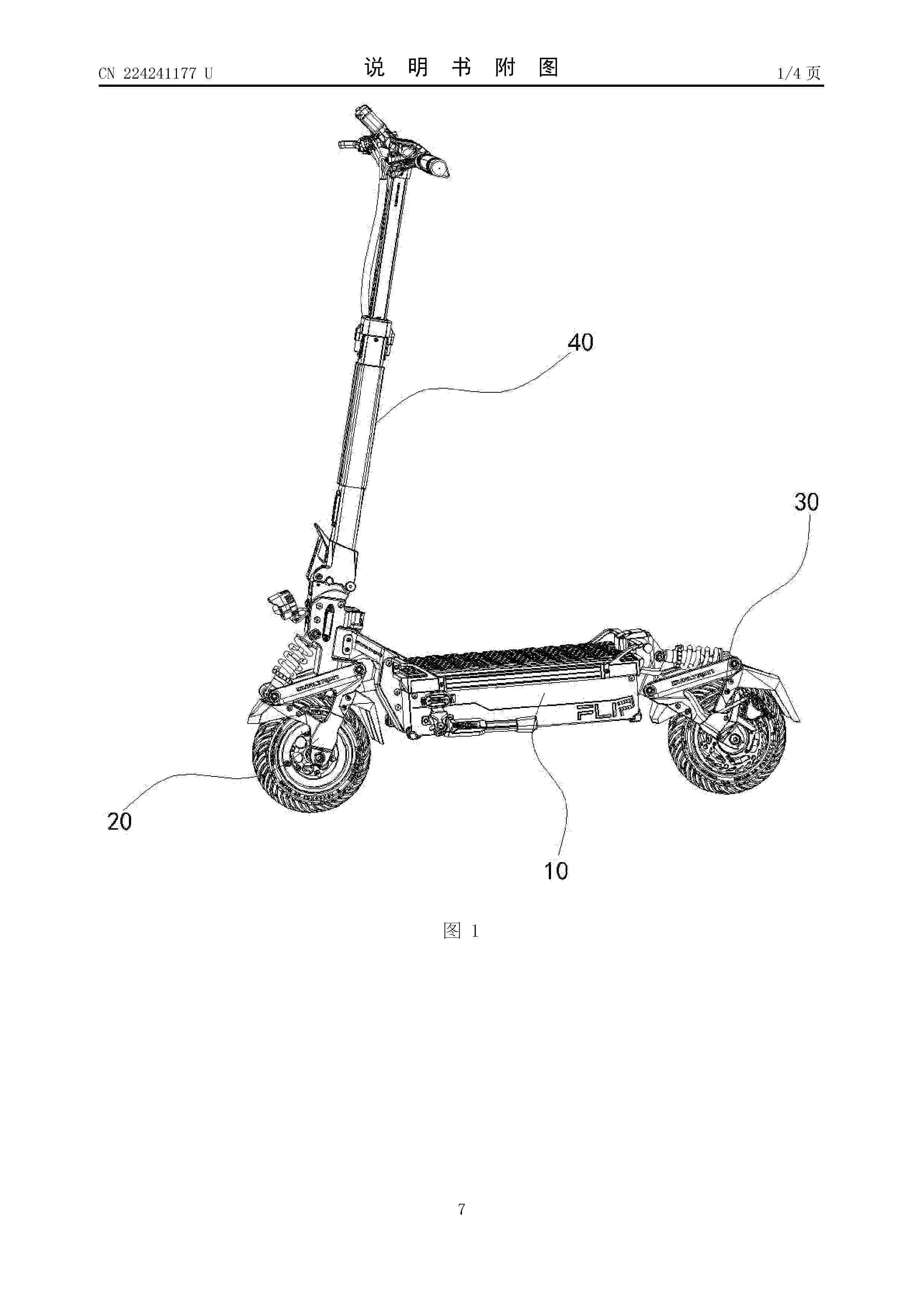
Resumen de: CN224241177U
The utility model discloses a folding electric scooter which comprises a pedal assembly, a front wheel assembly horizontally and rotatably arranged on the front side of the pedal assembly, a tail portion vertically and rotatably arranged on the pedal assembly and a steering assembly, and the steering assembly vertically rotates and is detachably arranged on the front wheel assembly. A limiting structure used for limiting the rear wheel assembly after rotation is arranged at the position of the rear wheel assembly and the pedal assembly. During folding, the rear wheel assembly is firstly rotated upwards, then the front wheel assembly is rotated, and finally the folding steering assembly and the rear wheel assembly are staggered and located above the pedal assembly through the folding steering assembly. The folding structure of the steering assembly is arranged on the horizontal rotating part, and during folding, the steering assembly is rotated and then folded, so that the rear wheel assembly and the steering assembly can be folded to the position above the pedal assembly in a staggered mode, and the size after folding is reduced to the maximum extent; in addition, double locking is conducted on the steering assembly by arranging two sets of locking mechanisms, the two sets of locking mechanisms have the advantages of being convenient to disassemble and fold, in addition, an adjustable limiting screw is arranged to abut against the interior of the containing groove so that the

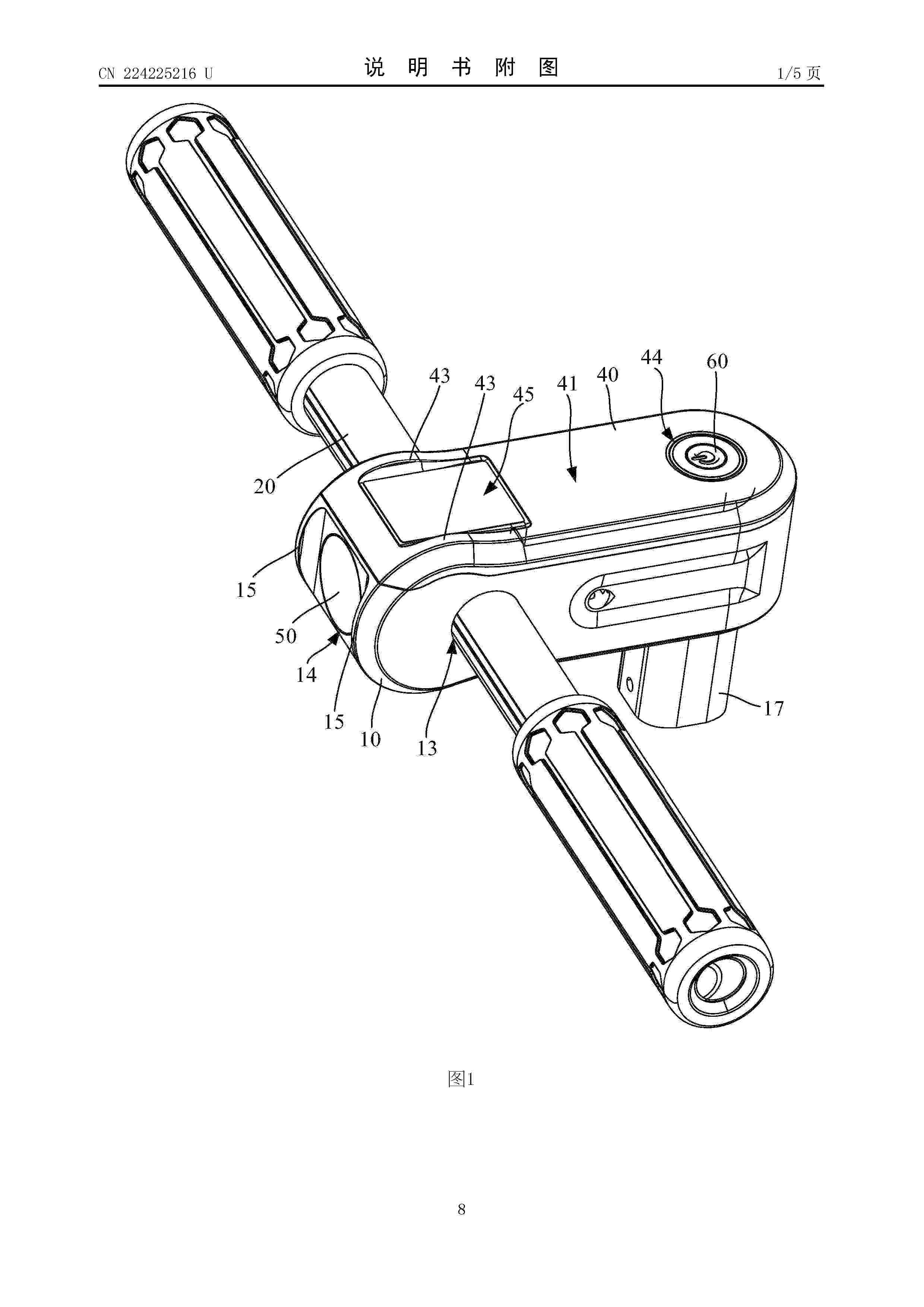
Resumen de: CN224225216U
The handle assembly comprises a handle seat, a transverse handle, a display assembly and a cover plate, the handle seat is provided with a connecting part, a first mounting hole and a mounting cavity, the connecting part is located at the bottom of the handle seat and located at the rear end of the handle seat, the mounting cavity is provided with an opening, the opening is located at the top of the handle seat, and the transverse handle is arranged in the mounting cavity. The first mounting hole penetrates through the two opposite sides of the handle base in the left-right direction of the handle base and is spaced from the opening, and the first mounting hole and the connecting part are spaced in the front-back direction of the handle base; the transverse handle is arranged in the first mounting hole in a penetrating manner and is fixed with the handle seat; the display assembly is arranged in the mounting cavity and located on the rear side of the transverse handle. The cover plate covers the opening, and a light-transmitting area is arranged at the position, corresponding to the display assembly, of the cover plate. According to the technical scheme, the installation stability of the transverse handle can be improved.
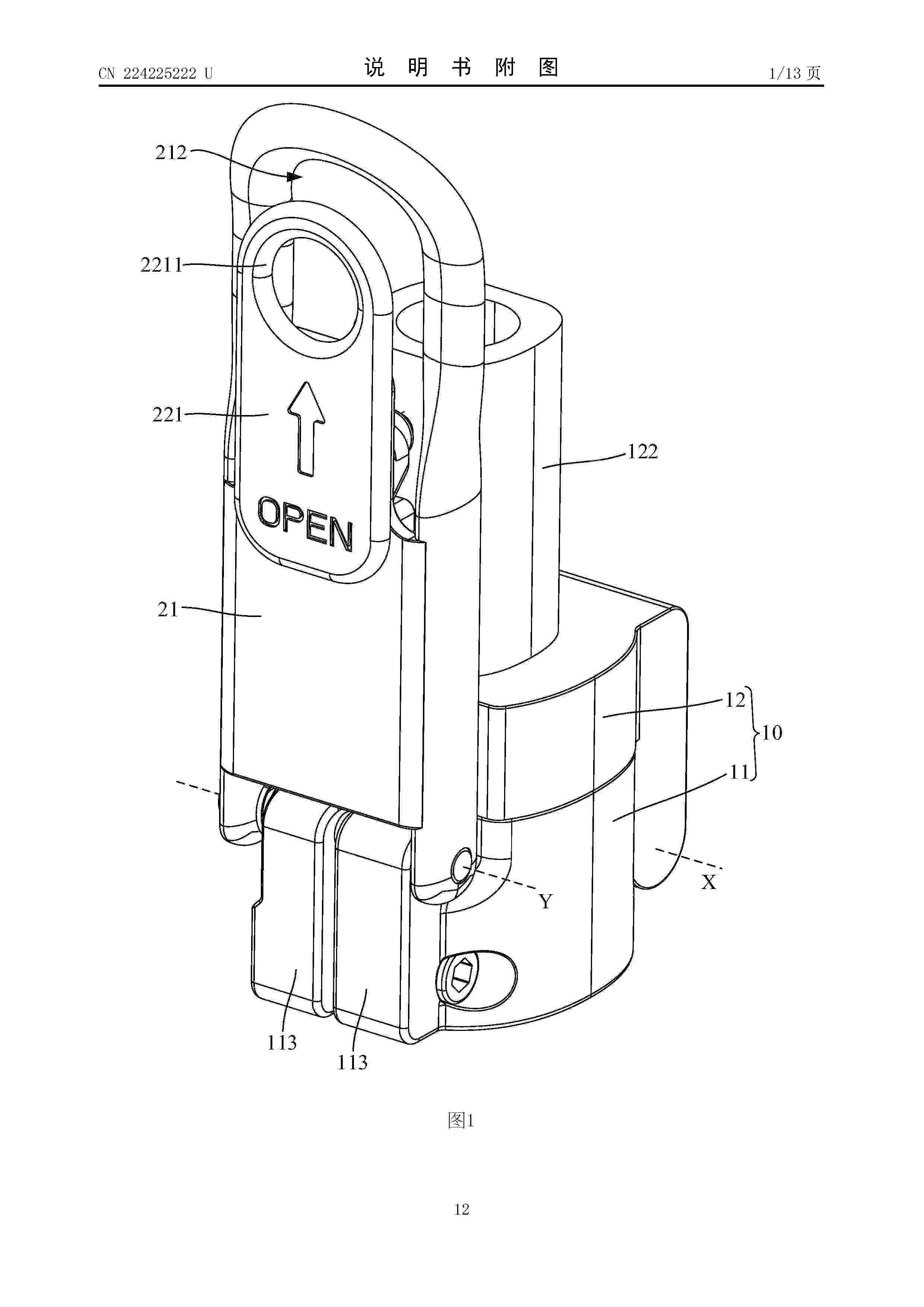
Resumen de: CN224225222U
The utility model discloses a folding mechanism and an electric scooter, the folding mechanism comprises a folding seat and a clamping mechanism, the folding seat comprises a first part and a second part, one side of the first part is hinged with one side of the second part, the first part is provided with a first rotating axis, and one side, far away from the first rotating axis, of the second part is provided with a first clamping part; the clamping mechanism comprises a mounting part, an unlocking part and an elastic part, the mounting part is hinged to the other side of the first part and provided with a second rotating axis parallel to the first rotating axis, the unlocking part is slidably mounted on the mounting part and exposed on the side, away from the second part, of the mounting part, and the elastic part is connected between the mounting part and the unlocking part; the folding mechanism has a use state in which the first part and the second part are stacked and a folding state in which the first part and the second part are unfolded, and in the use state, the mounting piece is close to one side, deviating from the first rotating axis, of the second part, and the unlocking piece is clamped to the first clamping part. The technical scheme of the utility model is convenient for users to use.
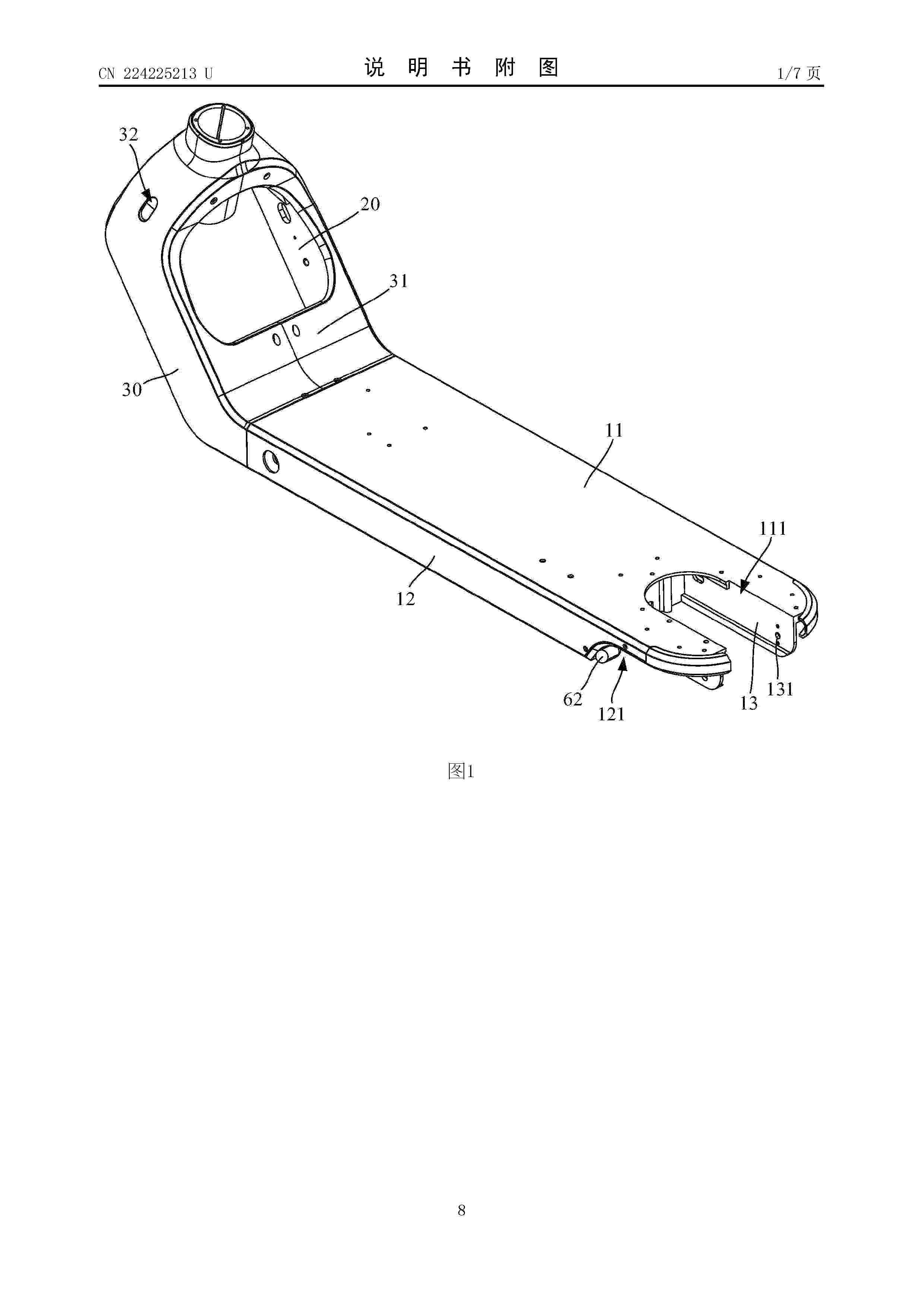
Resumen de: CN224225213U
The utility model discloses a scooter frame and an electric scooter, the scooter frame comprises a pedal, a mounting rack and a shell, and the rear end of the pedal is provided with a mounting space for mounting a rear wheel; the mounting frame comprises two opposite supporting parts and a mounting part connected between the ends of the two supporting parts, the mounting part is provided with a mounting shaft hole, the ends, away from the mounting part, of the supporting parts are connected to the front end of the pedal, and the two supporting parts are distributed in the width direction of the pedal at intervals; and the shell is arranged outside the mounting frame in a covering manner and extends to the front end of the pedal. According to the technical scheme, stability can be guaranteed while the width of the pedal is increased.
Resumen de: CN224225218U
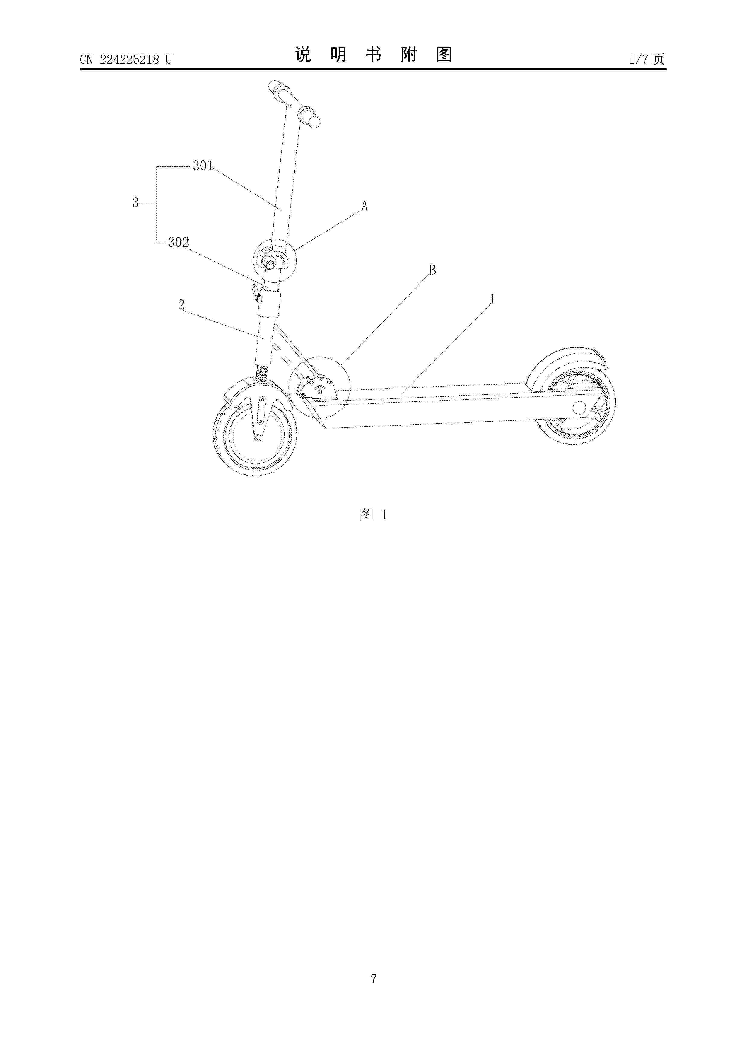
The utility model discloses a child electric scooter which comprises a scooter head part and a scooter body part, the scooter head part is rotationally arranged on the scooter body part, a first rotating mechanism is arranged at the hinged position of the scooter head part and the scooter body part, the scooter head part comprises a vertical pipe, and a second rotating mechanism used for bending the vertical pipe is arranged on the vertical pipe; the first rotating mechanism comprises a limiting plate arranged on the vehicle body part and a locking wrench rotationally arranged on the vehicle head part, a plurality of limiting grooves are formed in the limiting plate, and the vehicle head part is locked or unlocked by operating the locking wrench to enter or break away from the limiting grooves; the vertical pipe comprises an upper section and a lower section which are hinged to each other, the second rotating mechanism is arranged at the joint of the upper section and the lower section and comprises a mounting box, a driven gear is rotatably arranged in the mounting box, and a half-tooth structure is arranged at the bottom of the lower section.
Resumen de: CN224225221U
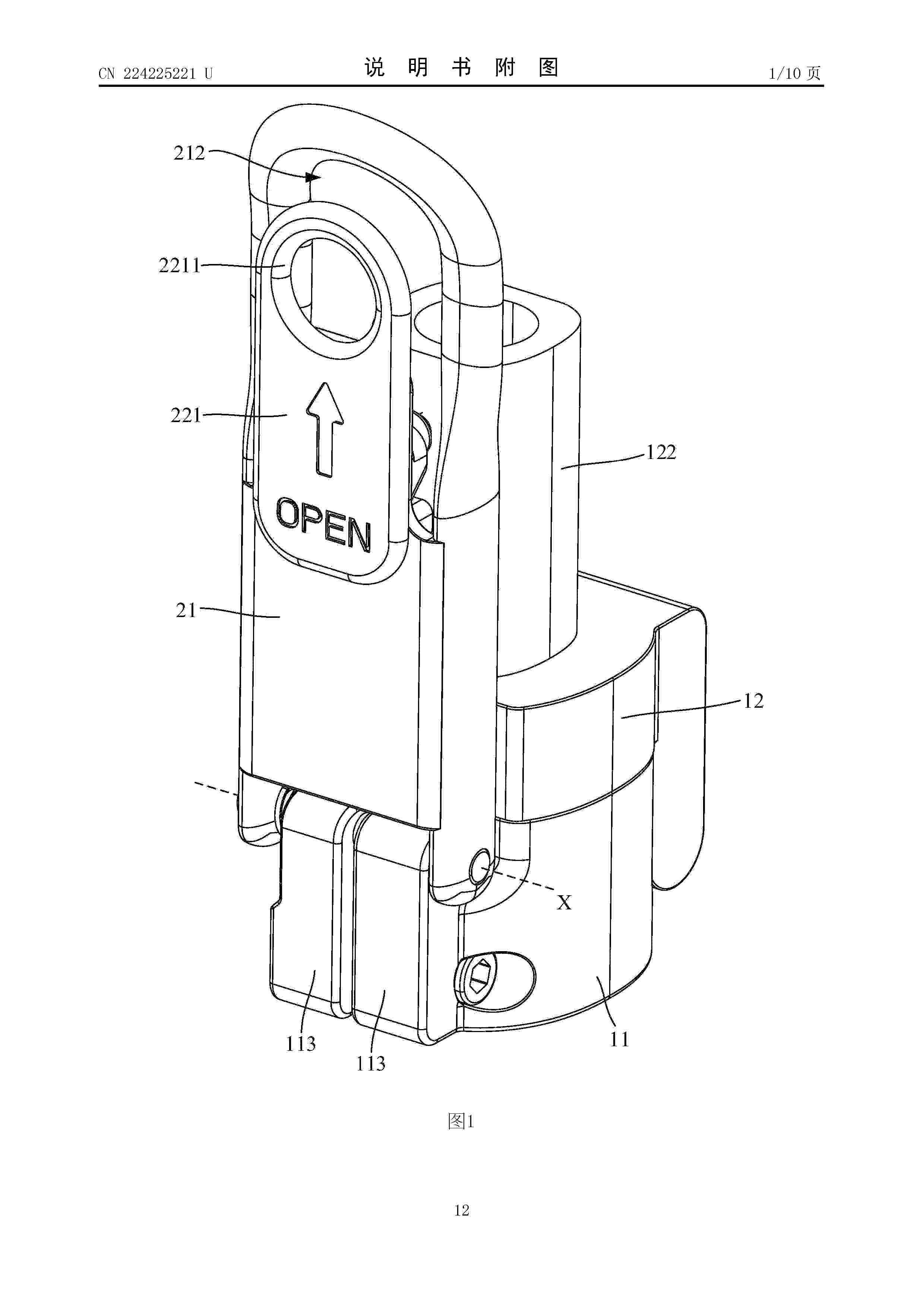
The utility model discloses a folding mechanism and an electric scooter, the folding mechanism comprises a folding seat, a lock catch mechanism and a limiting piece, the folding seat comprises a fixed seat and a rotating seat, one side of the fixed seat is hinged with one side of the rotating seat, and the rotating seat is provided with a first clamping part; the lock catch mechanism is rotationally mounted on the other side of the fixed seat and is provided with a first rotating axis, and an abutting part and a second clamping part are arranged on the side, facing the rotating seat, of the lock catch mechanism; the limiting piece is rotationally mounted on the other side of the rotating seat, and the limiting piece is at least provided with a second rotating axis parallel to the first rotating axis; the scooter folding mechanism has a using state that the fixed seat and the rotating seat are stacked and a folding state that the fixed seat and the rotating seat are unfolded, in the using state, the second clamping part is clamped with the first clamping part, and the limiting piece abuts against the side, facing the fixed seat, of the abutting part. According to the technical scheme, the reliability of the folding mechanism can be improved.
Resumen de: CN224225214U
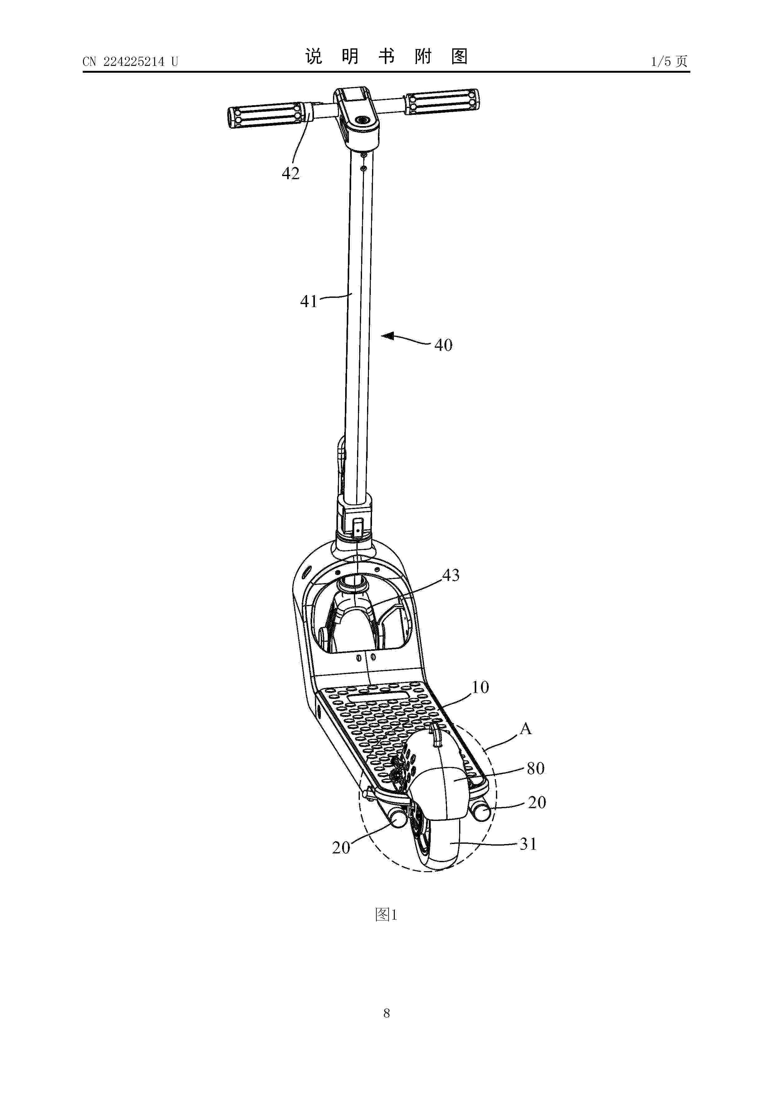
The utility model discloses an electric scooter which comprises a pedal, a rear wheel and two tail lamps, an installation space and two installation positions are arranged at the rear end of the pedal, and the two installation positions are arranged on the two opposite sides of the installation space respectively and are not higher than the upper surface of the pedal. The rear wheel is mounted in the mounting space; and the two tail lamps are respectively arranged at the two mounting positions and are spaced from the rear wheel. According to the technical scheme, the lighting effect of the tail lamp can be improved.
Resumen de: CN224225215U
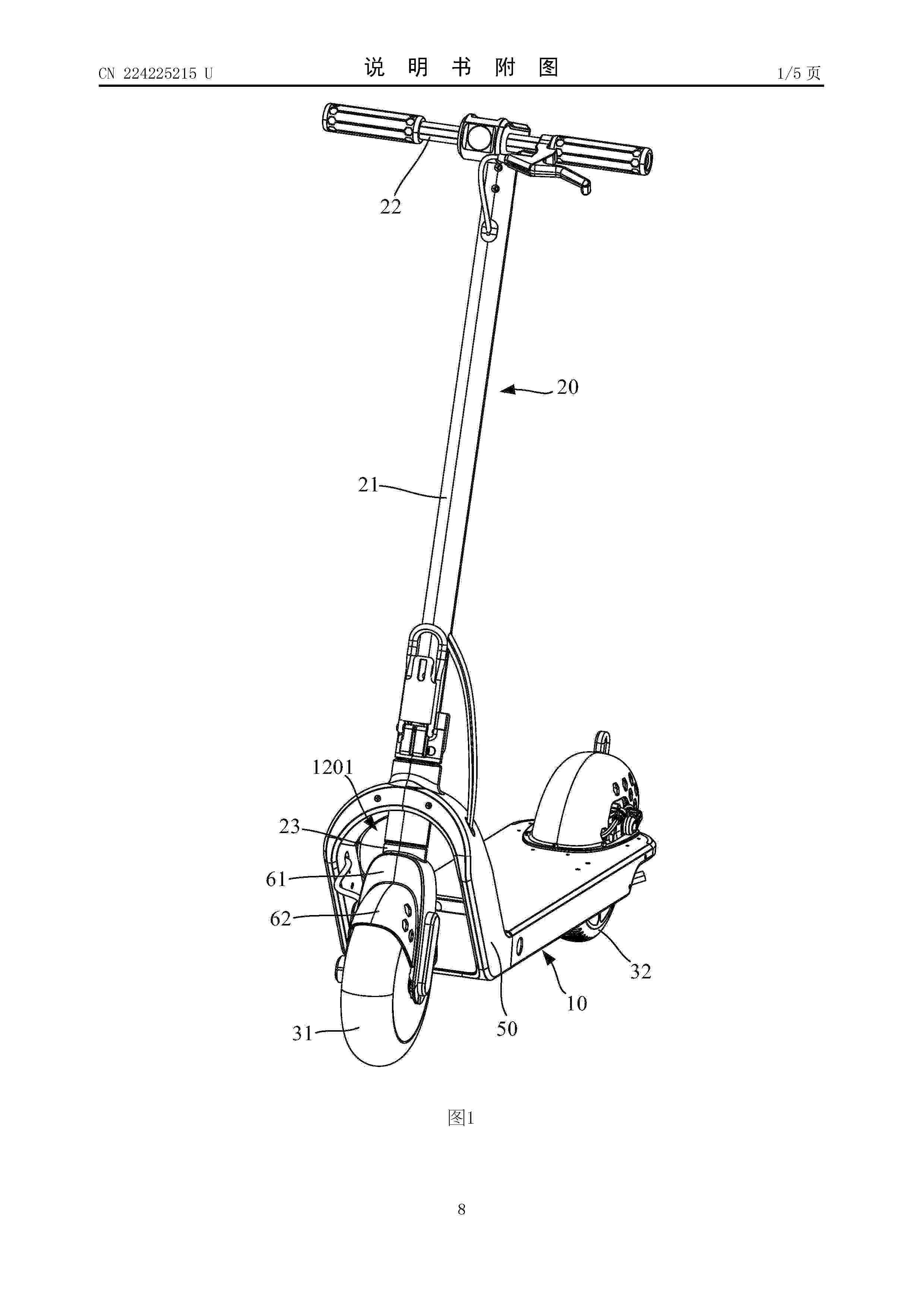
The utility model discloses an electric scooter which comprises a frame, a handlebar assembly and a front wheel, the frame comprises a pedal and an arch support, the arch support is located at the front end of the pedal and higher than the upper surface of the pedal, a containing space is formed below the arch support, and a mounting hole is formed in the arch crown of the arch support; the handlebar assembly comprises a vertical rod, a transverse handlebar arranged at the upper end of the vertical rod and a front fork arranged at the lower end of the vertical rod, one of the vertical rod and the front fork is rotationally mounted in the mounting hole, and the front fork is located in the containing space; a front wheel is installed on the front fork, and the front wheel is partially located in the installation space. According to the technical scheme, the structural strength of the frame can be improved, and durability is improved.
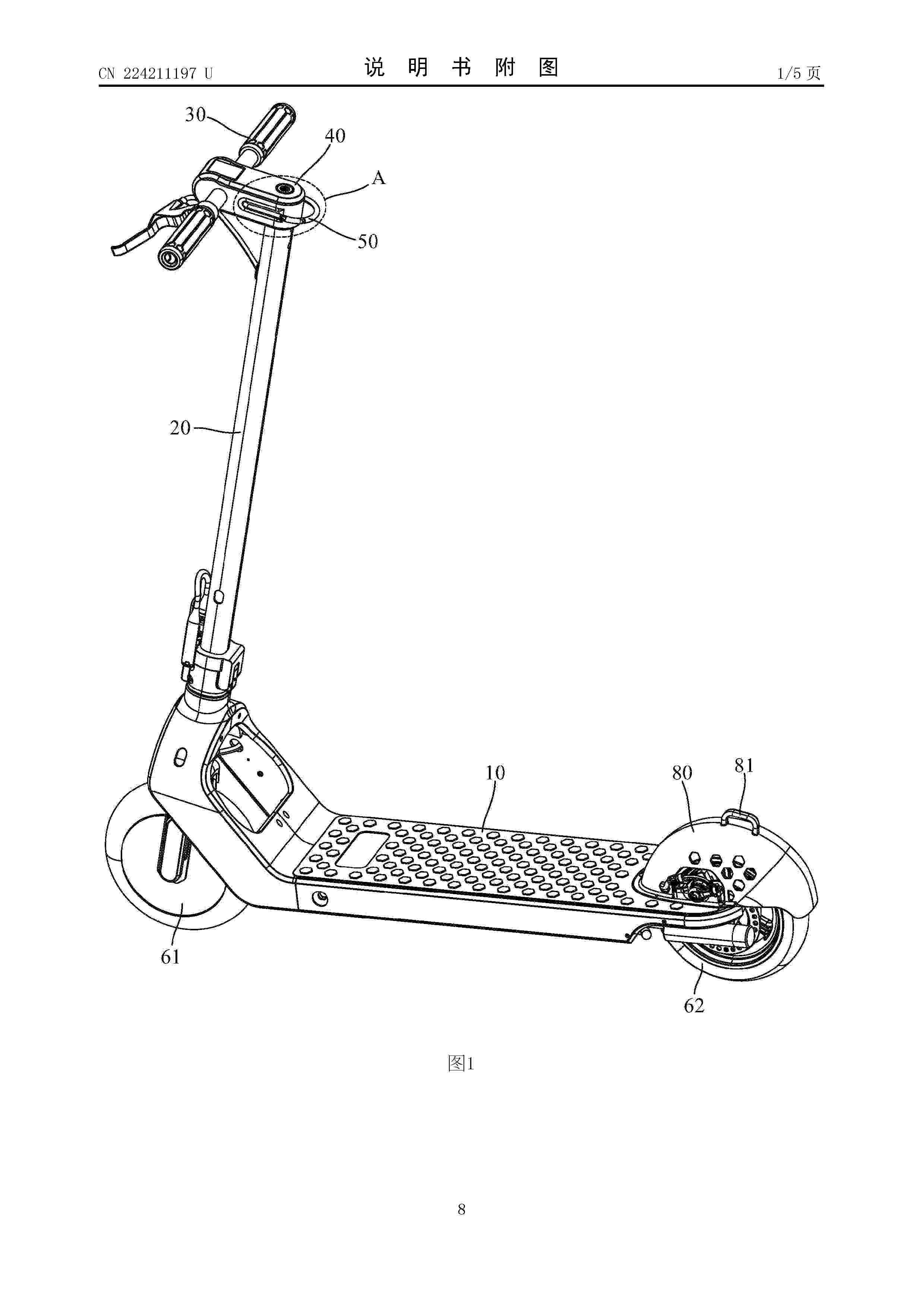
Resumen de: CN224211197U
The electric scooter comprises a scooter frame and a handlebar assembly, the handlebar assembly comprises a vertical rod, a handlebar seat, a transverse handlebar and a hanging piece, the vertical rod is installed at the front end of the scooter frame, one end of the handlebar seat is connected to the upper end of the vertical rod and extends towards the front side of the vertical rod, the transverse handlebar is installed on the handlebar seat, and the hanging piece is installed on the handlebar seat. The transverse handlebar is arranged on the handlebar seat and located on the front side of the vertical rod, the hanging piece is installed on the handlebar seat and provided with a hanging part, the hanging part is located on the rear side of the handlebar seat and extends in the length direction of the transverse handlebar, and the hanging part and the rear end face of the handlebar seat are spaced. According to the technical scheme, a user can hang articles conveniently.
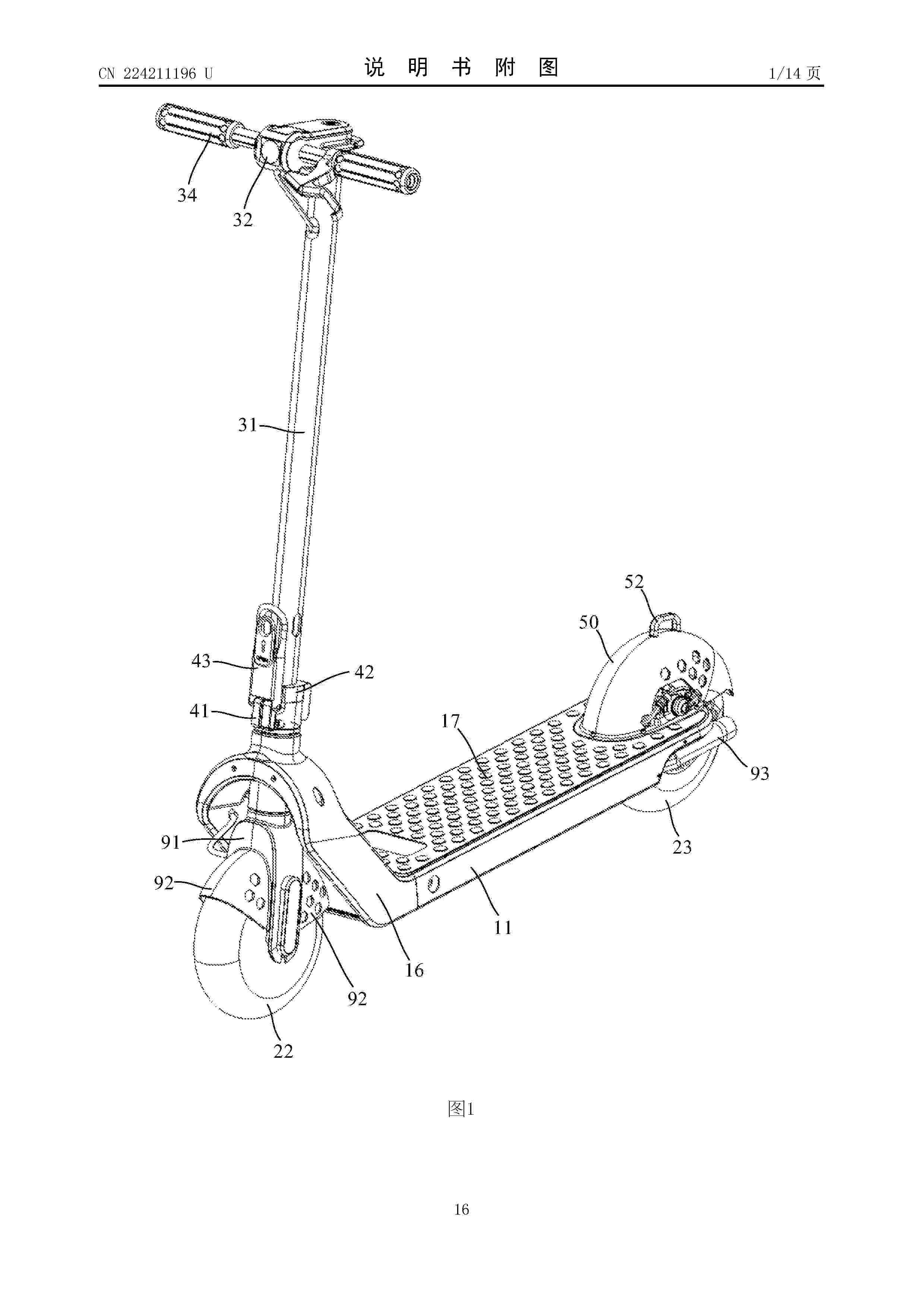
Resumen de: CN224211196U
The utility model discloses an electric scooter which comprises a pedal assembly, a front fork, a front wheel, a handlebar assembly, a rear wheel and a rear mud cover, and an installation notch is formed in the rear end of the pedal assembly. The front fork is rotationally mounted at the front end of the pedal assembly; the front wheel is mounted on the front fork; the handlebar assembly comprises a vertical pipe, and the vertical pipe is connected with the front fork through a folding mechanism, so that the handlebar assembly has a folding state that the vertical pipe is transversely arranged above the pedal assembly and a using state that the vertical pipe is beneficial to the upper portion of the front fork. The rear wheel is mounted in the mounting notch; the rear mud cover is provided with an opening and a mounting part extending along the periphery of the opening, the rear mud cover is arranged above the mounting notch in a covering mode through the opening so as to cover the rear wheel cover inside, the mounting part is connected with the edge part of the mounting notch, a hooking part is arranged at the top of the rear mud cover, and in the folding state, the handlebar assembly is buckled to the hooking part. According to the technical scheme, the use reliability of the electric scooter in the folded state can be improved.
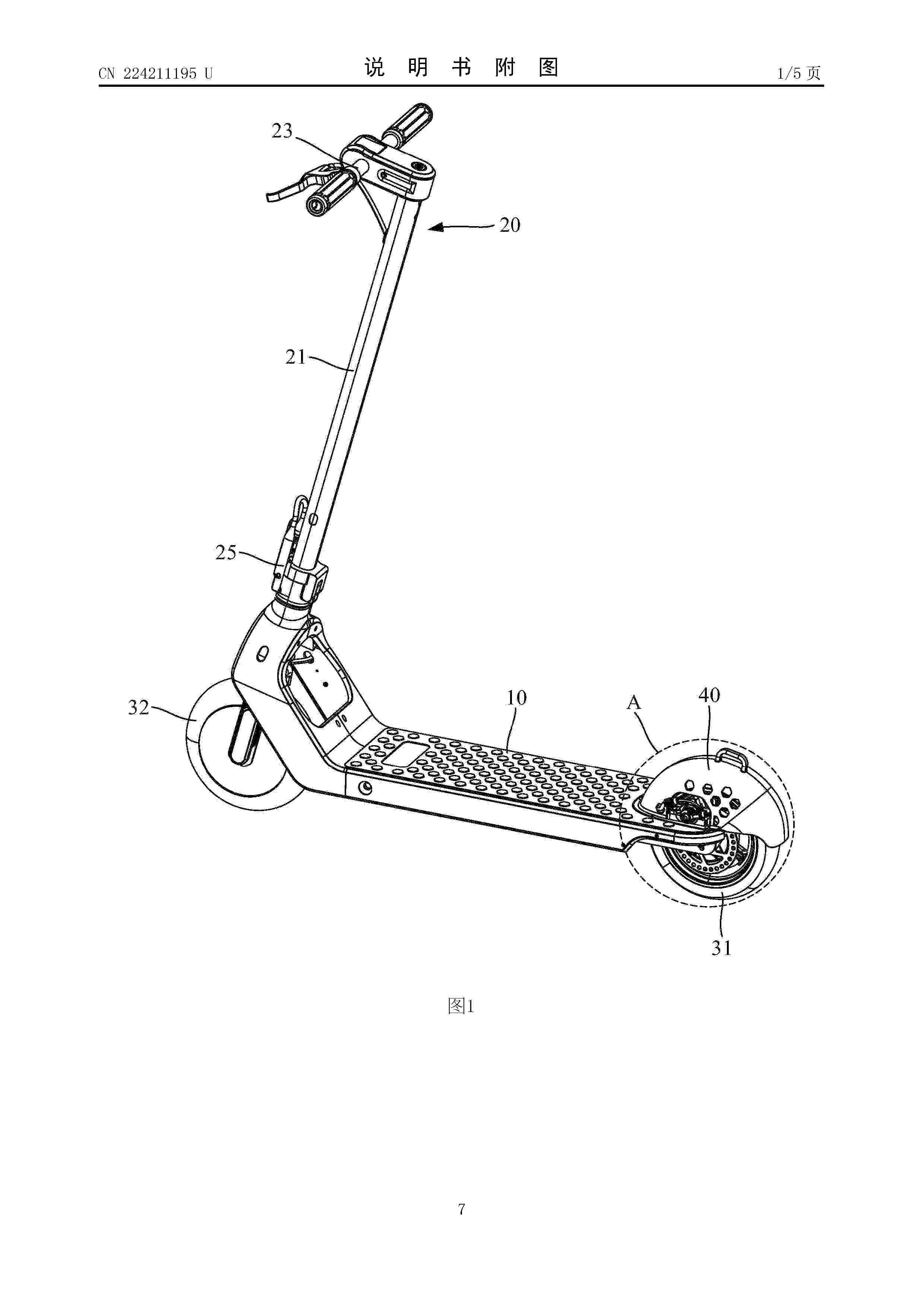
Resumen de: CN224211195U
The utility model discloses an electric scooter which comprises a pedal, a rear wheel and a mud cover, the rear end of the pedal is provided with an installation space and an installation part, the installation space penetrates through the upper surface of the pedal, and the installation space surrounds the edge of the installation space; the rear wheel is mounted in the mounting space and protrudes relative to the upper surface of the pedal; the mud cover is provided with a mounting opening and a mounting turnup surrounding the outer side of the mounting opening, and the mounting turnup is correspondingly mounted above the mounting part, so that the rear wheel is covered with the mud cover. According to the technical scheme, the mud blocking effect can be improved.
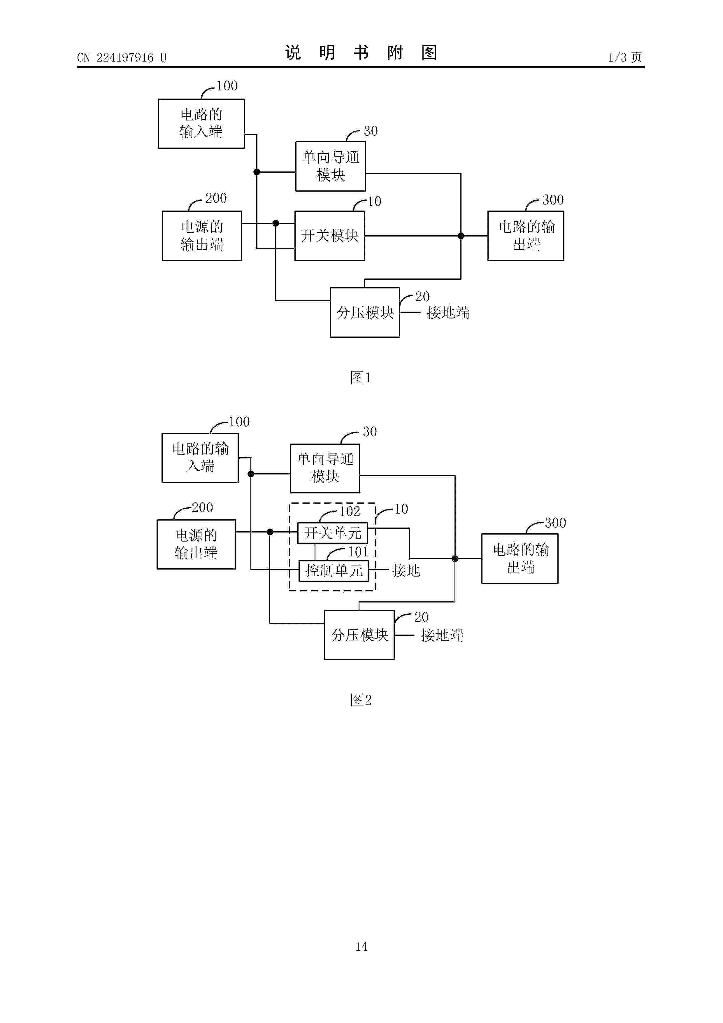
Resumen de: CN224197916U
According to the identification circuit, the battery and the electric scooter, the switch module is connected between the output end of the power supply and the output end of the circuit, and the control end of the switch module is connected with the input end of the circuit; the voltage division module is connected to the output end and the grounding end of the power supply, and the output end of the voltage division module is connected with the output end of the circuit; the one-way conduction module is connected to the input end of the circuit and the output end of the circuit; according to the circuit, different output results can be respectively output when the input ends of the circuit are in three conditions, so that when only one interface is used for ID identification, a battery management system can identify a plurality of batteries based on the identification circuit.
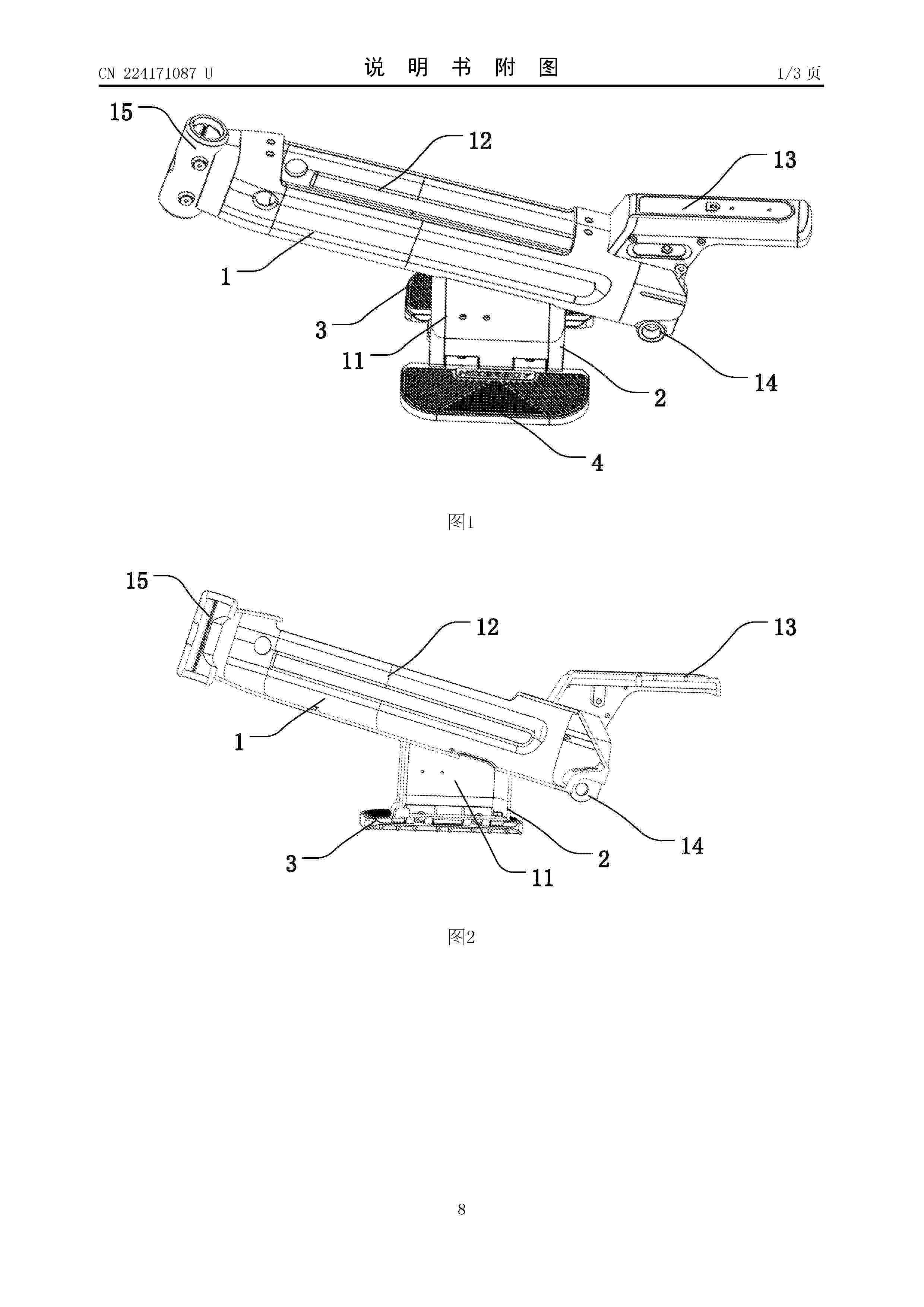
Resumen de: CN224171087U
The utility model discloses a frame with a foldable pedal and an electric scooter. The pedal mounting frame is arranged at the lower end of the main beam, the pedal base is detachably mounted on the pedal mounting frame, and the first pedal and the second pedal are rotatably connected to the two sides of the pedal base, so that the first pedal and the second pedal can be unfolded or folded, the pedal base can move the pedal downwards, and the pedal mounting frame is arranged on the main beam. And the first pedal and the second pedal are large in area and good in comfort, the occupied space of the folded structure is small, the pedal can be replaced in a disassembly mode when damaged, and the maintenance cost is reduced.
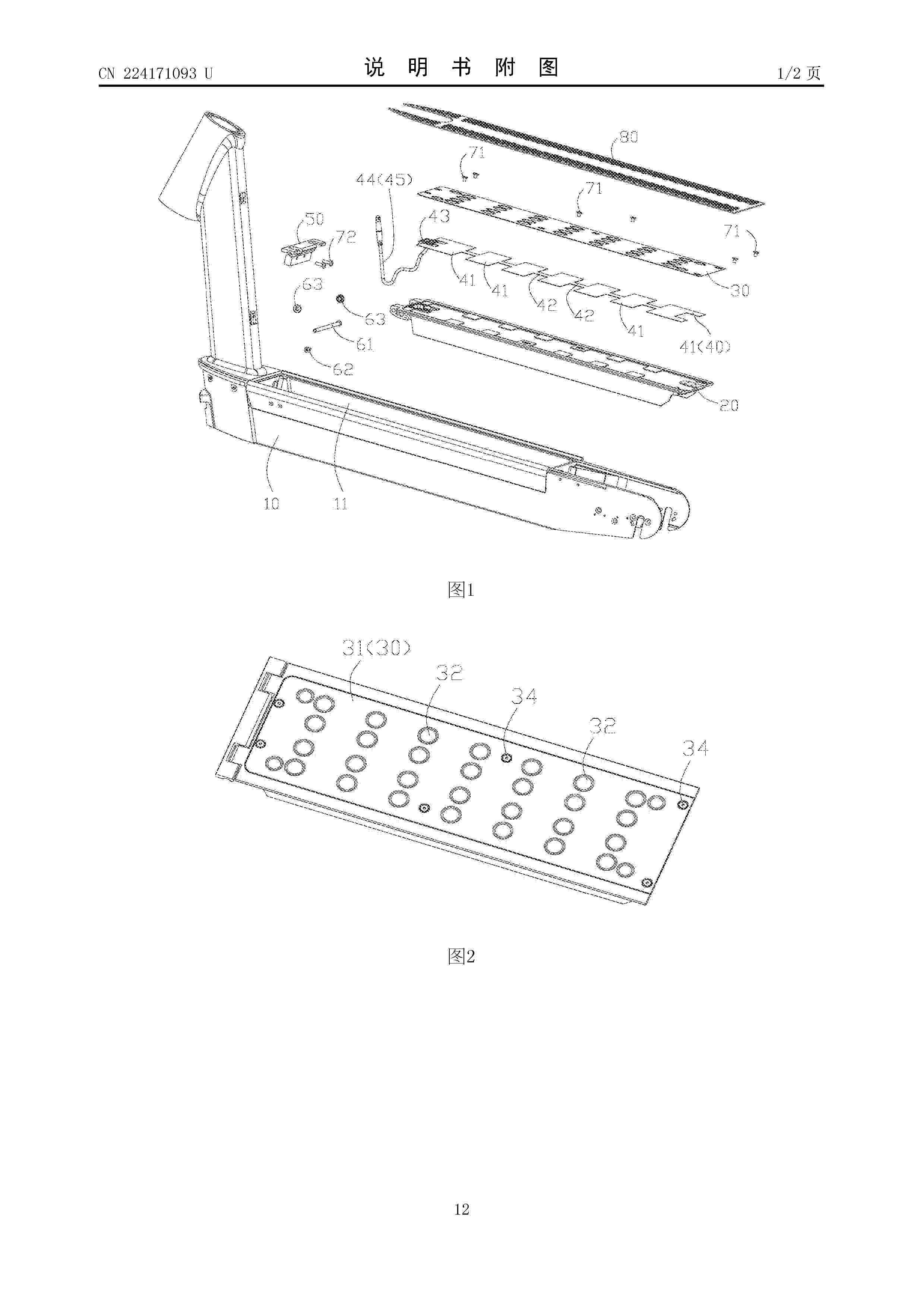
Resumen de: CN224171093U
The utility model provides an electric scooter which comprises a scooter frame, a pedal, a cover plate and a sensor assembly, and the pedal is installed above the scooter frame and used for bearing a rider; a first groove is formed in the upper surface of the pedal, and/or a second groove is formed in the lower surface of the cover plate; the cover plate is connected with the upper surface of the pedal, and a containing cavity located between the cover plate and the pedal is formed by the first groove and/or the second groove during connection; the sensor assembly comprises a plurality of pressure sensors distributed on the upper surface of the pedal at intervals, and the pressure sensors are fixed in the containing cavity. Thus, the pressure sensor can be used for detecting the actual number of people bearing the electric skateboard, the cover plate can be used for fixedly installing the pressure sensor and can also protect the pressure sensor, and the electric skateboard is simple in structure and good in protection performance on the pressure sensor.
Nº publicación: KR20260056632A 27/04/2026
Solicitante:
이승준
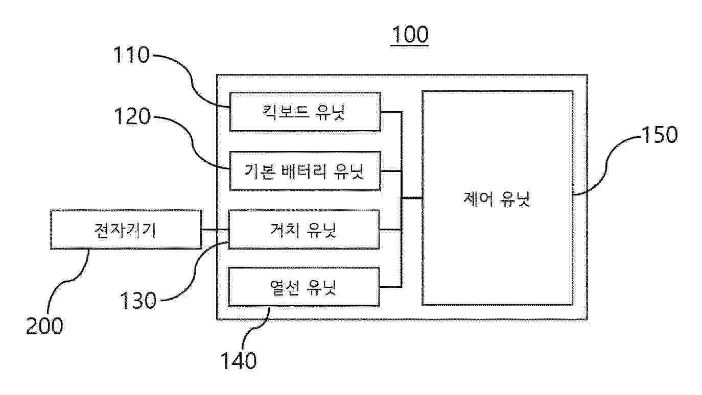
Resumen de: KR20260056632A
본 발명에 따른 열선이 장착된 전동킥보드는, 바퀴, 사용자가 기립하거나 착석하기 위한 지지판, 및 핸들을 포함하는 킥보드 유닛; 상기 킥보드 유닛에 착탈 가능하게 장착되어, 출력을 제공하기 위한 기본 배터리 유닛; 상기 킥보드 유닛에 장착되어 전자기기를 착탈 가능하게 고정하기 위한 거치 유닛; 상기 핸들에 내장되어 열을 발산시키기 위한 열선 유닛; 및 상기 기본 배터리 유닛 및 상기 전자기기의 배터리 중 어느 하나를 선택하여 상기 열선 유닛에 전원이 공급되도록 하는 제어 유닛;을 포함하는 것을 특징으로 할 수 있다.
 BOPI
BOPI
 Sede Electrónica