Si deseas distinguir tus productos, servicios o ambos de los de otra empresa, es posible que necesites una marca o nombre comercial. Descubre qué son, en qué consiste su procedimiento de registro y qué implica.

Información sobre los plazos de presentación de solicitudes de transformación de marcas de la Unión Europea en marca nacional española. Más información


Si tienes un nuevo dispositivo, producto o procedimiento que resuelva un problema técnico o tenga una ventaja práctica, existen distintas formas de protegerlo en España y en otros países. Descubre cómo hacerlo.

¿Tu innovación reside en la estética, la ornamentación o la apariencia de tu producto? Protégela mediante un diseño industrial. Descubre qué derechos confiere el registro y cómo realizar la tramitación.

Las indicaciones geográficas protegen el nombre de un producto originario de una zona geográfica, a la cual le debe una determinada calidad, reputación u otra característica. Descubre qué son, en qué consiste su procedimiento de registro y qué beneficios conceden.

Las patentes publicadas en todo el mundo son una valiosa fuente de información científica, técnica y comercial.

Si eres emprendedor/a o una empresa y quieres potenciar y mejorar la rentabilidad de tu negocio protegiendo de forma adecuada los activos intangibles de tu organización, en este espacio encontrarás lo necesario.


 471
resultados
471
resultados
 Última actualización
01/05/2026 [06:57:00]
Última actualización
01/05/2026 [06:57:00]


Resumen de: DE102024210479A1
Das Verfahren (10) zur Bestimmung der Katalysatorfähigkeit einer Katalysatorschicht von Komponenten (110, 120), die in einer Brennstoffzellenanlage eingebaut werden können, umfasst die Messung eines Verlaufs einer Messgröße (200) durch mindestens einen Sensor (140), der an der Komponente (110, 120) oder einer ihrer Zu- und/oder Ableitungen angebracht ist, während die Komponente (110, 120) auf ihre Betriebstemperatur gebracht wird und/oder von dieser abgekühlt wird. Der gemessene Verlauf der Messgröße (200) wird mit einem Referenzzustand der Messgröße verglichen. Aus dem gemessenen Verlauf (200) wird die Katalysatorfähigkeit berechnet. Dieses Verfahren ermöglicht eine genaue und zuverlässige Bestimmung der Katalysatorfähigkeit, was für die Optimierung der Leistung, Effizienz und Wartungskosten von Brennstoffzellenanlagen von entscheidender Bedeutung ist.

Resumen de: US20260115669A1
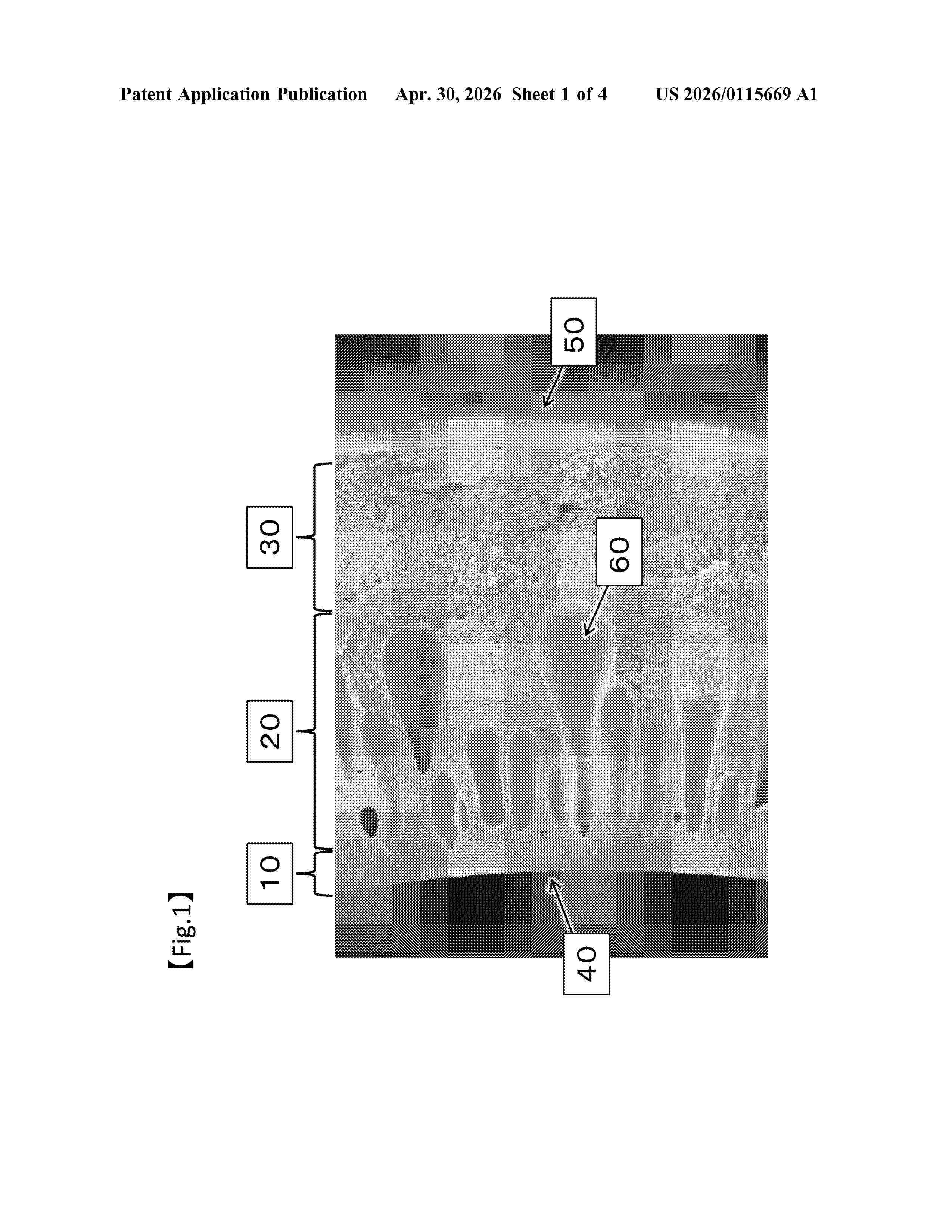
The present disclose relates to a hollow fiber membrane including a fine pores layer, a coarse pores layer, and a strength retention layer.
Resumen de: DE102024210316A1
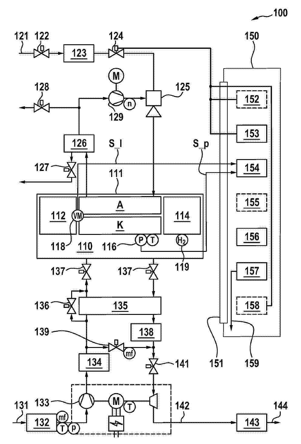
Die Erfindung betrifft ein Verfahren zum Überwachen eines Brennstoffzellensystems (100) auf Wasserstoffleckage. Das Verfahren umfasst einen Schritt des Erkennens einer durch mindestens ein Wasserstoffdosierventil (124) des Brennstoffzellensystems (100) abgesperrten Wasserstoffzufuhr zu einer Anode (A) des Brennstoffzellensystems (100). Ferner umfasst das Verfahren einen Schritt des Einlesens eines Drucksensorsignals (S_p) über eine Schnittstelle (151) von einer Druckerfassungseinrichtung (116) des Brennstoffzellensystems (100). Das Drucksensorsignal (S_p) repräsentiert Anodendruckwerte, die einen tatsächlichen Druckabfall in der Anode (A) anzeigen oder aus denen der tatsächliche Druckabfall in der Anode (A) ermittelbar ist. Zudem umfasst das Verfahren einen Schritt des Durchführens eines Vergleichs zwischen dem Drucksensorsignal (S_p) und einem bestimmten Referenzwert, um Vergleichsdaten zu erzeugen. Das Verfahren umfasst auch einen Schritt des Überprüfens der Vergleichsdaten auf Erfüllung eines vordefinierten, eine Wasserstoffleckage anzeigenden Leckagekriteriums, um ein Überwachungsergebnis (159) zu ermitteln.
Resumen de: DE102024210444A1
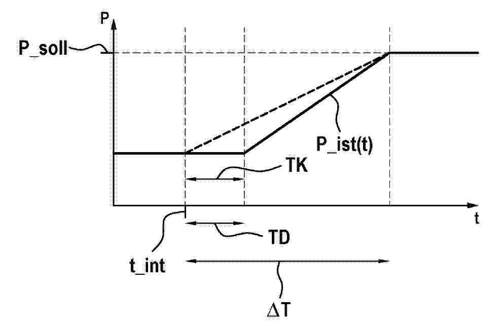
Die vorliegende Erfindung betrifft ein Verfahren zum Betreiben eines Brennstoffzellensystems (1), gemäß welchem bei einer angeforderten Änderung einer gelieferten elektrischen Leistung (P_ist) auf eine angeforderte elektrische Leistung (P_soll) eine Einbringrate (n) eines Brennstoffs zur Versorgung eines Stacks (2) geändert wird.Dabei wird eine Transportdauer (TD) des Brennstoffs zwischen dem Einbringen des Brennstoffs und dem Erreichen des Stacks (2) berücksichtigt.Die Erfindung betrifft zudem ein Computerprogrammprodukt zur Ausführung des Verfahrens sowie ein derart betriebenes Brennstoffzellensystem (1).
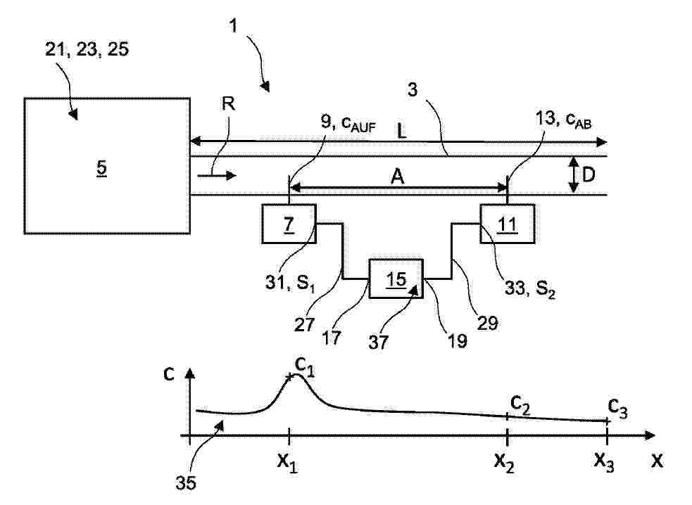
Resumen de: DE102024131229A1
Die vorliegende Erfindung betrifft ein Verfahren zum Bestimmen einer tatsächlichen Wasserstoffkonzentration c eines Abluftstroms einer Brennstoffzelle, das die folgenden Schritte umfasst: - Ermitteln eines zu einer stromaufwärtigen Wasserstoffkonzentration korrespondierenden ersten Wasserstoffkonzentrationssignals S1 des Abluftstroms; - Ermitteln eines zu einer stromabwärtigen Wasserstoffkonzentration korrespondierenden zweiten Wasserstoffkonzentrationssignals S2 des Abluftstroms; - Bestimmen einer die tatsächliche Wasserstoffkonzentration abbildenden Wasserstoffkonzentrationsfunktion c(x), wobei x eine Position in Strömungsrichtung des Abluftstroms definiert; und - Berechnen der tatsächlichen Wasserstoffkonzentration anhand der Wasserstoffkonzentrationsfunktion c(x); dadurch gekennzeichnet, dass die ermittelten Wasserstoffkonzentrationssignale S1, S2 als zwei voneinander getrennte Eingangsgrößen in die Wasserstoffkonzentrationsfunktion c(x) übergeben werden.
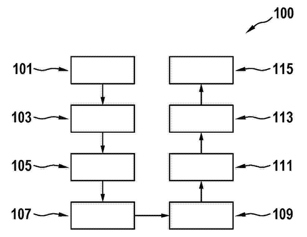
Resumen de: DE102024210404A1
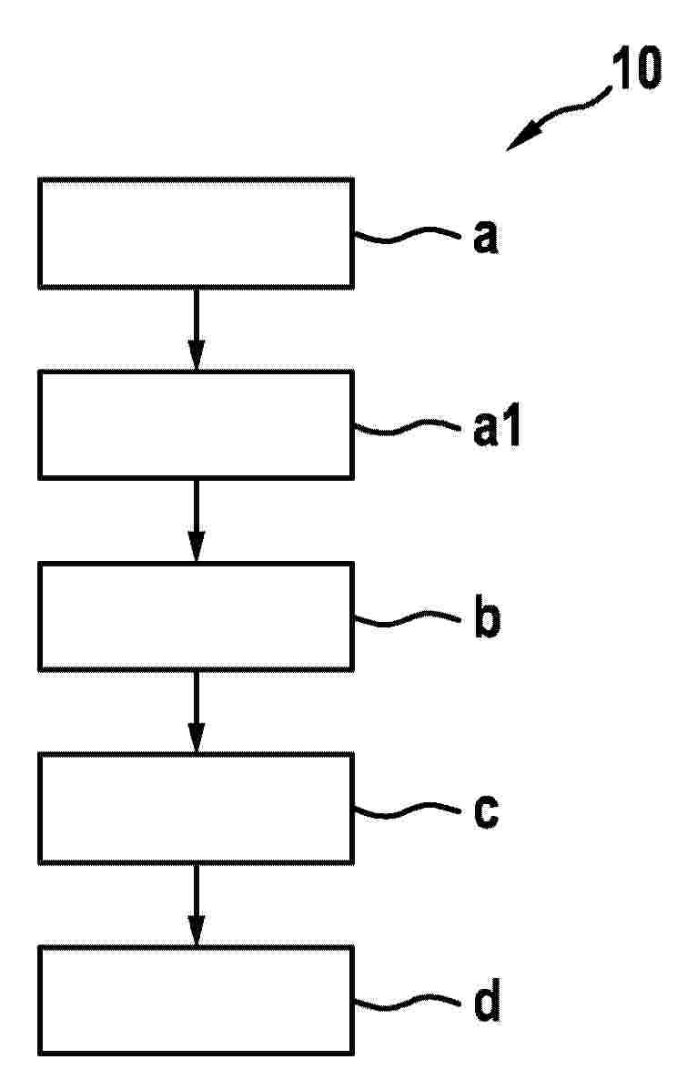
Die vorgestellte Erfindung betrifft ein Verfahren (100) zur Diagnose eines Zustands eines Brennstoffzellensystems (200), wobei das Verfahren (100) umfasst:- Starten (101) des Brennstoffzellensystems (200) mit geschlossenen Anodenabsperrventilen (207) und geschlossenen Kathodenabsperrventilen (209),- Öffnen (103) der Anodenabsperrventile (207) während die Kathodenabsperrventile (209) geschlossen bleiben,- Einleiten (105) von frischem Wasserstoff in einen Anodenraum (203) eines Brennstoffzellenstapels (201) des Brennstoffzellensystems (200), während ein Kathodenraum (205) des Brennstoffzellenstapels (201) abgeschlossen ist,- Aufprägen (107) eines elektrischen Aufladestroms auf den Brennstoffzellenstapel (201), mit einer relativ zu einem nachfolgenden Normalbetrieb umgekehrten Polarität, sodass eine an jeweiligen Brennstoffzellen des Brennstoffzellenstapels (201) anliegende Spannung steigt,- Bestimmen (109) eines Zustands des Brennstoffzellensystems (200) anhand eines Spannungsverlaufs an mindestens einer Brennstoffzelle des Brennstoffzellenstapels (201) und/oder eines mittels mindestens eines an dem Anodenraum (203) angeordneten Anodendrucksensors gemessenen Anodendrucks,- Öffnen (111) der Kathodenabsperrventile (209) und- Ausgeben (113) des Zustands durch eine Ausgabeschnittstelle (215).
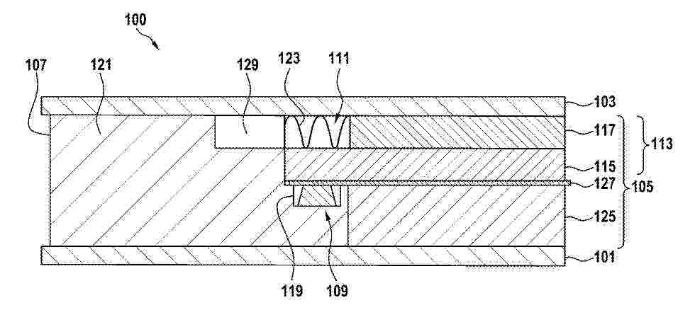
Resumen de: DE102024210403A1
Die vorgestellte Erfindung betrifft eine Zelle (100) für einen elektrochemischen Energiewandler (300), wobei die Zelle (100) umfasst:- ein erstes Polarplattenelement (101),- ein zweites Polarplattenelement (103),- eine Membranelektrodenanordnung (MEA) (105),- einen Rahmen (107), der die MEA (105) umgibt, und- eine Terrassendichtung (109),wobei die MEA (105), der Rahmen (107) und die Terrassendichtung (109) zwischen dem ersten Polarplattenelement (101) und dem zweiten Polarplattenelement (103) angeordnet sind,wobei die MEA (105) ein elastisches Element (111) umfasst undwobei das elastische Element (111) die Terrassendichtung (109) überlagert.
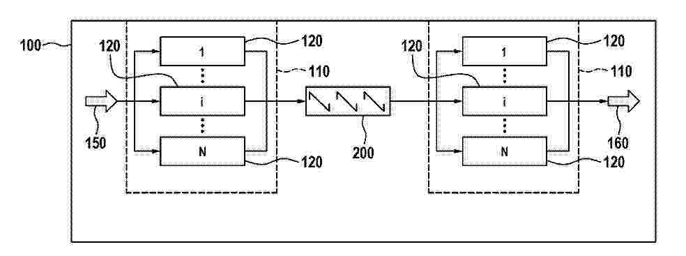
Resumen de: DE102024210510A1
Die Erfindung umfasst ein Brennstoffzellenmodul (100) für eine Brennstoffzellenanlage (140). Das Brennstoffzellenmodul (100) ist so konzipiert, dass mindestens zwei Brennstoffzellenstacks (110) in Reihe geschaltet sind, und dass der Gasaustritt eines vorgeschalteten Brennstoffzellenstacks (110) als Gaseintritt eines nachfolgenden Brennstoffzellenstacks (110) genutzt werden kann. Trotz des Fehlens einer Anodenabgasrezirkulation zeichnet sich das Brennstoffzellenmodul (100) durch einen Wirkungsgrad von über 60% aus.
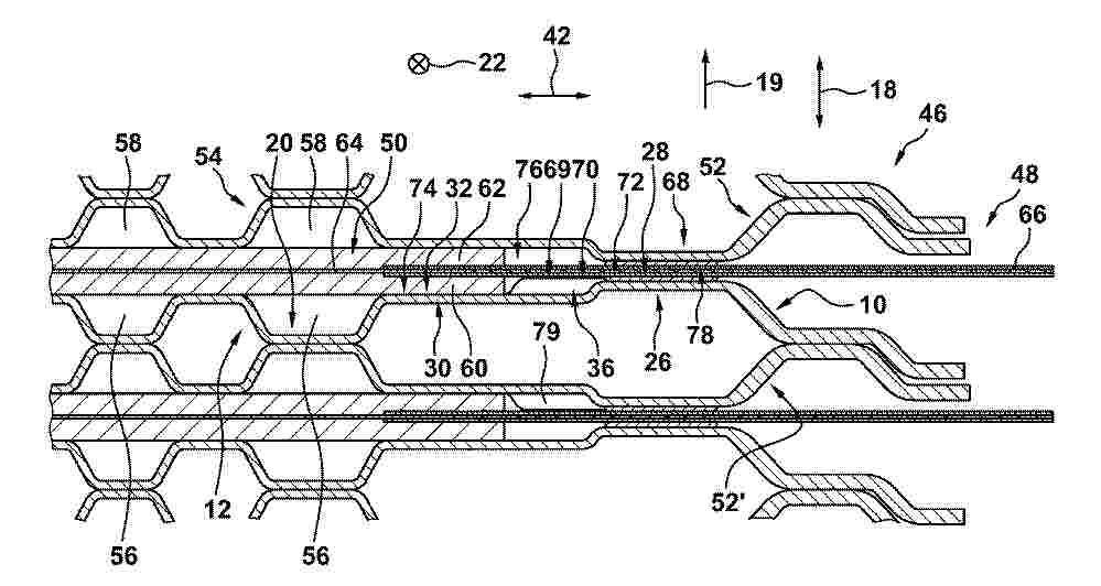
Resumen de: DE102024210273A1
Die Erfindung betrifft eine Bipolarplatte (10) für eine Brennstoffzelle, aufweisend eine durch sich in eine Vertikalrichtung (18) erstreckende Vertiefungen (20) gebildete Kanalstruktur (12) zur Durchströmung mit einem Reaktionsgas, einen die Kanalstruktur (12) lateral randseitig umgebenden Dichtbereich (26), der eine Dichtoberfläche (28) aufweist, die zur Abdichtung derKanalstruktur (12) nach außen an einem Dichtelement (66) anliegbarist, einen Auflagebereich (30) mit einer Auflageoberfläche (32) zur lateral randseitigen Auflage eines die Kanalstruktur (12) überspannbaren Membran-Elektroden-Aufbaus (50), eine Sperroberfläche (69) aufweisende Sperrmittel (34) zur Begrenzung einer Bypassströmung des Reaktionsgases lateral außerhalb der Kanalstruktur (12), wobei in Bezug auf die Vertikalrichtung (18) eine Höhenlage (72) der Dichtoberfläche (28) größer als eine Höhenlage (74) der Auflageoberfläche (32) ist, wobei eine Höhenlage (70) der Sperroberfläche (69) gleich wie oder größer als eine Höhenlage (72) der Dichtoberfläche (28) ist. Weiterhin betrifft die Erfindung einen Brennstoffzellenstapel (46) mit einer derartigen Bipolarplatte (10).
Resumen de: US20260116262A1
A method for controlling fuel cell power generation of a vehicle is introduced. The method may comprise obtaining driving information about at least two upcoming segments of a road, wherein the at least two upcoming segments are segments of the road to be driven by the vehicle driving on a current segment. The method may further comprise estimating, based on the obtained driving information, a required fuel cell output value of the current segment. The method may also comprise determining, based on the current segment being a segment for regenerative braking and based on the required fuel cell output value, whether to perform fuel cell power generation control of the vehicle. Based on the determining, the method may control power generation of a fuel cell of the vehicle.
Resumen de: DE102024131581A1
Um eine Plattenlage, beispielsweise für einen Elektrolyseur oder eine Brennstoffzelle, umfassend einen Träger und beidseitig des Trägers angeordnete Elastomerprofillagen, die insbesondere auf der jeweiligen Seite des Trägers verlaufende Funktionsprofile bilden, wobei die Elastomerprofillagen sich bis zu einer Plattenlagenkante erstrecken und auf den einander gegenüberliegenden Seiten des Trägers einander gegenüberliegende, an die Plattenlagenkante angrenzende Endkantenbereiche bilden, derart zu verbessern dass ein Ablösen der Endkantenbereiche der Elastomerprofillagen verhindert wird, wird vorgeschlagen, dass der längs der Plattenlagenkante zwischen den einander gegenüberliegenden Endkantenbereiche liegende Träger mindestens einen an die Plattenlagenkante angrenzenden und sich in den Träger hinein erstreckenden Ausschnitt aufweist, in welchem ein die Endkantenbereiche verbindendes und diese relativ zueinander in Anlage an an dem Träger haltendes Verbindungsstück liegt.
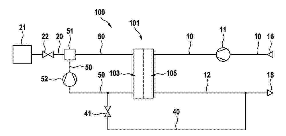
Resumen de: DE102024210307A1
Die Erfindung betrifft ein Verfahren zur Regelung der Stöchiometrie λ auf einer Anodenseite eines Brennstoffzellensystems (100), bei dem Wasserstoff über einen Wasserstoffpfad (20) einer Anode (103) eines Brennstoffzellenstapels (101) zugeführt und über einen Anodenkreis (50) rezirkuliert wird, wobei die Rezirkulation mit Hilfe einer in den Anodenkreis (50) integrierten Rezirkulationspumpe (52) bewirkt wird. Abhängig vom Stickstoff-Anteil im Anodengas wird die Stöchiometrie λ angepasst.Die Erfindung betrifft ferner ein Brennstoffzellensystem (100) zur Durchführung des Verfahrens.
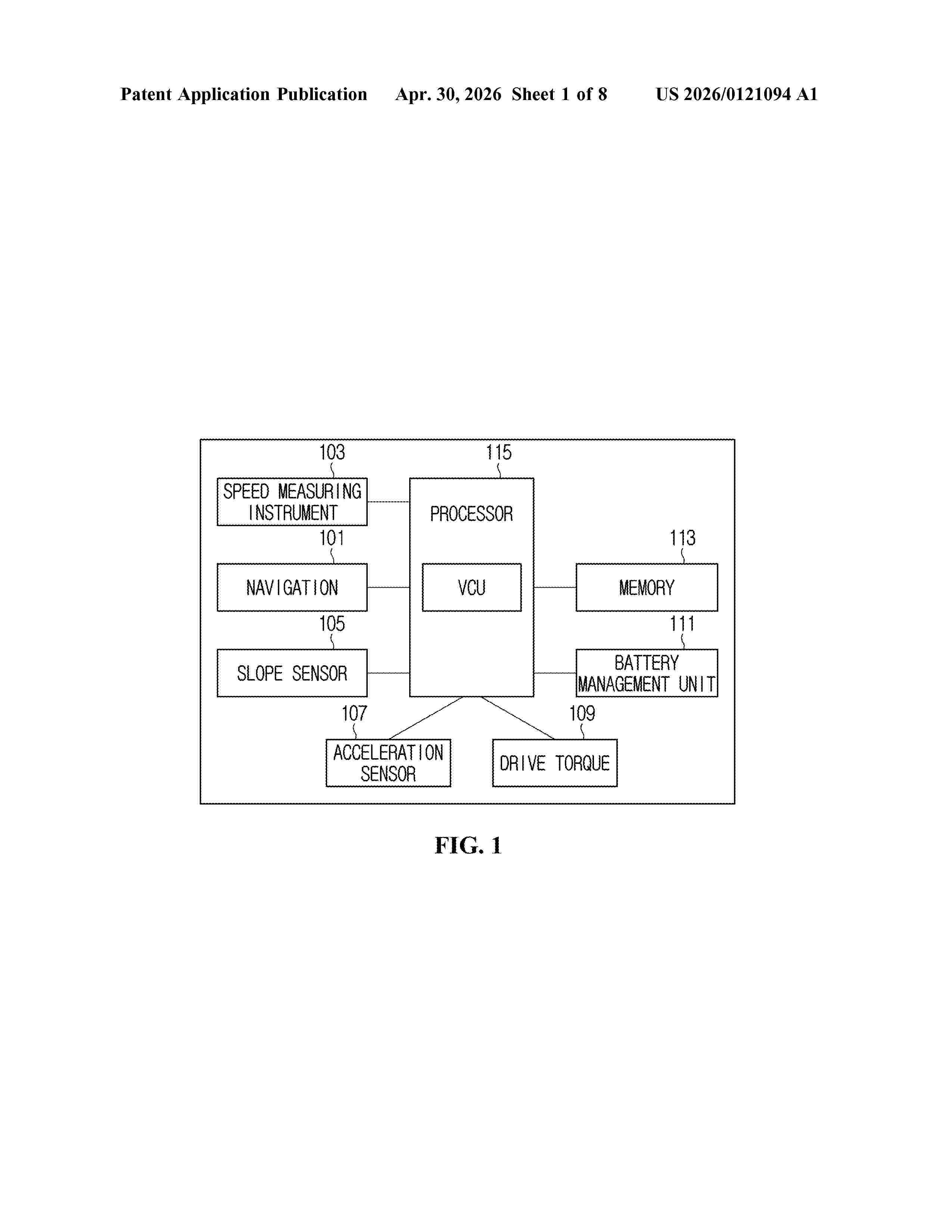
Resumen de: US20260121094A1
A method for controlling power generation of a fuel cell of a vehicle is disclosed. The method may comprise obtaining driving information about an upcoming segment of a road to be driven by the vehicle driving on a current segment of the road. The method may further comprise determining, based on the driving information, a required fuel cell output value of the current segment. Based on the driving information and the required fuel cell output value, the method may comprise determining whether to limit power generation of the fuel cell. The method may further comprise controlling, based on the determining, reduction of power generation of the fuel cell such that a power supply for driving the vehicle in the current segment is provided from a battery of the vehicle.
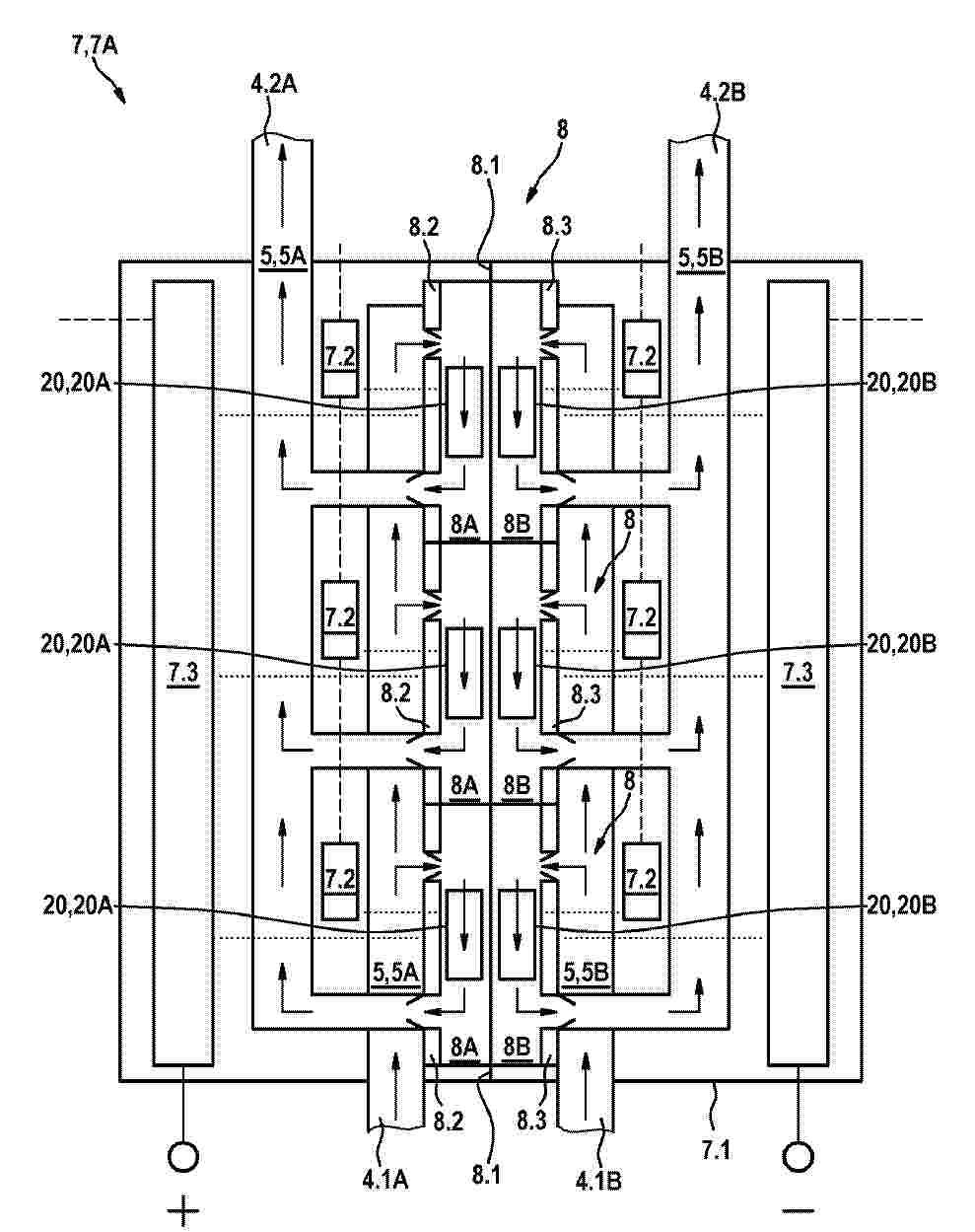
Resumen de: DE102024210281A1
Die Erfindung betrifft eine Energiespeicheranordnung mit einem Redox-Energiespeicher (7), welcher mehrere Redox-Flusszellen (8) umfasst und über zwei Kanalsysteme mit zwei Elektrolytbehältern verbunden ist, in welchen jeweils ein elektrisch leitender Elektrolyt (5) gespeichert ist, und einem MHD-Modul, welches eine Auswerte- und Steuereinheit und für die einzelnen Redox-Flusszellen (8) jeweils zwei in die einzelnen Redox-Flusszellen (8) integrierte magnetohydrodynamische Pumpmodule (20) umfasst, wobei die Auswerte- und Steuereinheit ausgeführt ist, die magnetohydrodynamischen Pumpmodule (20) über mindestens eine Ansteuereinheit (7.2) anzusteuern, wobei die zwei magnetohydrodynamischen Pumpmodule (20) mindestens eine Magnetvorrichtung (24) und jeweils eine Elektrodenvorrichtung (22) umfassen, welche ausgeführt ist, einen von der Ansteuereinheit (7.2) bereitgestellten elektrischen Strom innerhalb der korrespondierenden Redox-Flusszelle (8) durch den korrespondierenden elektrisch leitenden Elektrolyt (5) zu leiten, so dass durch Zusammenwirken mit einem von der Magnetvorrichtung (24) erzeugten Magnetfeld eine Lorentzkraft entsteht, welche den elektrisch leitenden Elektrolyt (5) innerhalb der korrespondierenden Redox-Flusszelle (8) gezielt beschleunigt, so dass ein resultierender Druckaufbau einen gewünschten Volumenstrom des elektrisch leitenden Elektrolyts (5) durch das korrespondierende Kanalsystem und den Redox-Energiespeicher (7) bewirkt.
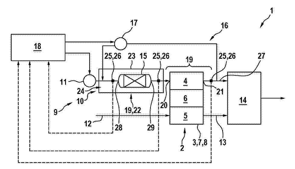
Resumen de: DE102024210445A1
Die vorliegende Erfindung betrifft ein Brennstoffzellensystem (1) mit zumindest einer Brennstoffzelle (3) sowie einem Kanalsystem (9) zur fluidischen Versorgung der Brennstoffzelle (3) sowie dem Abführen von Abgasen der Brennstoffzelle (3).Das Kanalsystem (9) weist zumindest ein Hochtemperaturabschnitt (19) mit erhöhten Temperaturen auf, wobei eine Sensorik (24) im Hochtemperaturabschnitt (19) einen Gassensor (25) aufweist.
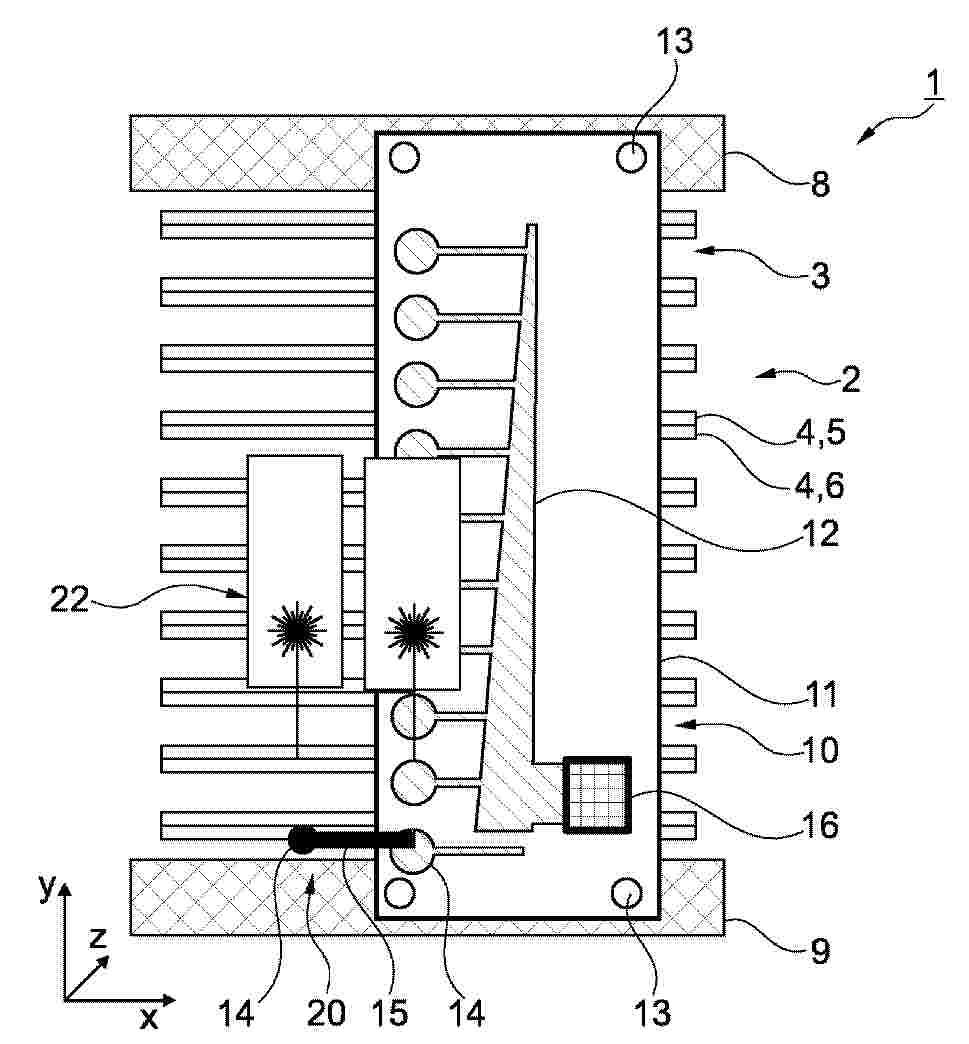
Resumen de: DE102024131657A1
Eine elektrische Verbindungsanordnung für stapelförmig angeordnete Bipolarplatten (4) eines elektrochemischen Systems (1), insbesondere Brennstoffzellensystems, sieht vor, dass mehrere Bipolarplatten (4) per Drahtbonden mit mindestens einer langgestreckten Platine (11) verbunden sind, welche sich in Stapelrichtung der Bipolarplatten (4) erstreckt, und durch welche eine Verbindung zu einem elektrischen Messsystem (10) hergestellt ist.
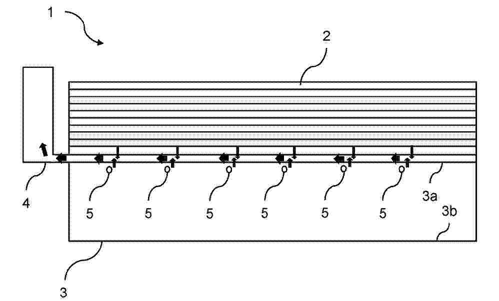
Resumen de: DE102024131603A1
Die Erfindung betrifft eine Endplatte (3) für einen Brennstoffzellenstapel (1). Die Endplatte (3) ist eingerichtet, im montierten Zustand derart an einem Ende des Brennstoffzellenstapels (1) anzuliegen, dass mittels der Endplatte (3) eine Spannkraft in Stapelrichtung auf den Brennstoffzellenstapel (1) übertragbar ist. Die Endplatte (3) weist eine Heizeinrichtung (5) auf, welche in der Endplatte (3) angeordnet und eingerichtet ist, zumindest einen Teil des Brennstoffzellenstapels (1) zu erwärmen, insbesondere einen Stromsammler (4) der zwischen der Endplatte (3) und Brennstoffzellen (2) des Brennstoffzellenstapels (1) angeordnet ist.
Resumen de: DE102024131066A1
Die Erfindung betrifft einen Membranstapel (1) für einen Membranbefeuchter. Der Membranstapel (1) umfasst mehrere Membranen (2) und mehrere Abstandshalter (3). Wenigstens einer der Abstandshalter (3) umfasst ein erstes Teilstück (6a) und ein zweites Teilstück (6b). Die Teilstücke (6a, 6b) sind voneinander separat ausgebildet und zu dem wenigstens einen Abstandshalter (3) verbunden.Die Erfindung betrifft auch einen Membranbefeuchter mit dem Membranstapel (1).
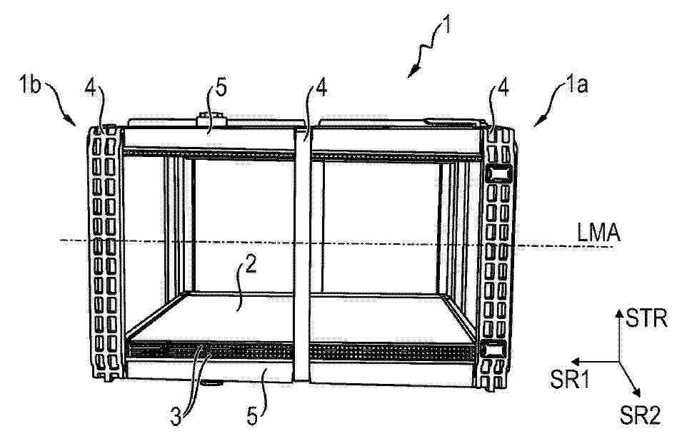
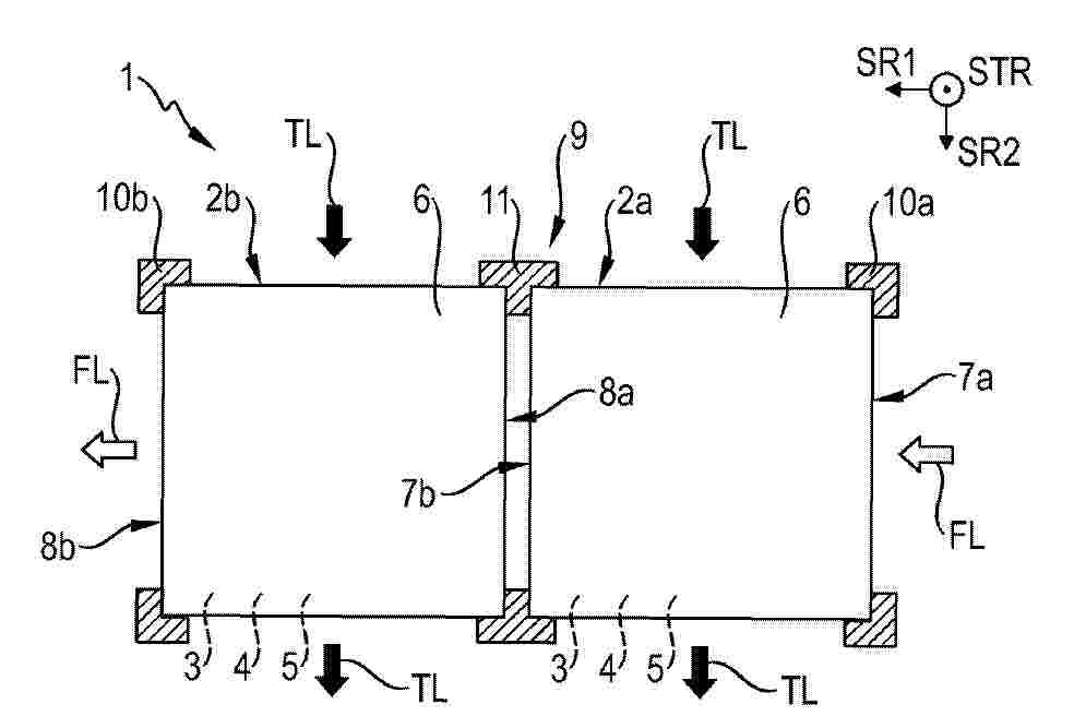
Resumen de: DE102024131079A1
Die Erfindung betrifft eine Membranstapelanordnung (1) für einen Membranbefeuchter (12) mit zwei voneinander separaten Membranstapel (2a, 2b). Die Membranstapel (2a, 2b) sind dabei in eine erste Strömungsrichtung (SR1) nebeneinander und nacheinander durchströmbar angeordnet.Die Erfindung betrifft auch einen Membranbefeuchter (12) mit der Membranstapelanordnung (1) und eine Brennstoffzellenanlage mit dem Membranbefeuchter (12).
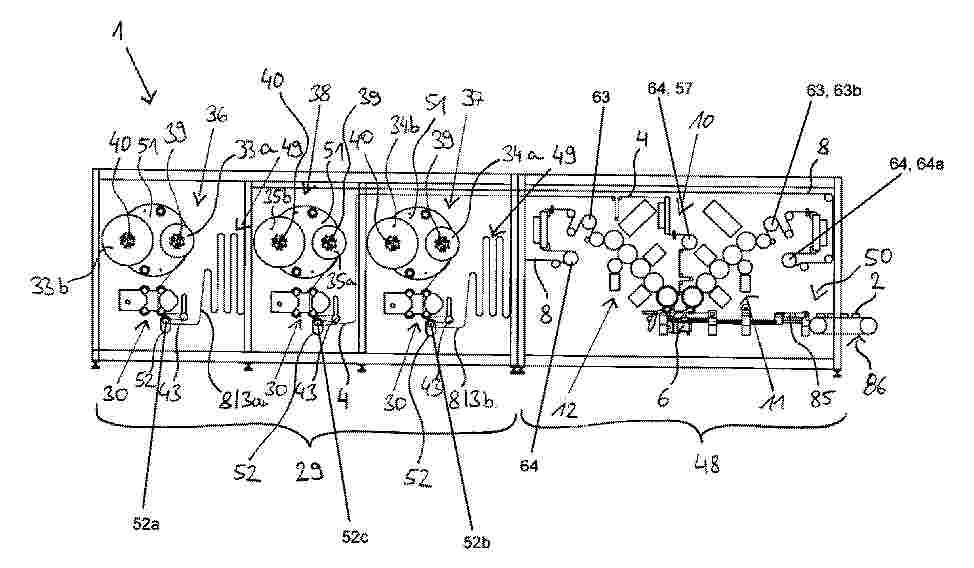
Resumen de: DE102024131377A1
Vorrichtung (1) für die Energiezellen produzierende Industrie zum Bilden eines Stapels (2), der eine Vielzahl von Segmenten (3) und eine Materialbahn (4) umfasst, wobei die Vorrichtung (1) dazu eingerichtet ist, die Materialbahn (4) zickzackförmig zu falten und die Segmente (3) derart auf der Materialbahn (4) abzulegen, dass bei dem Stapel (2) die Segmente (3) in den Falten (5) der Materialbahn (4) angeordnet sind, wobei die Vorrichtung (1) die folgenden Komponenten umfasst: einen Stapeltisch (6), auf dem der Stapel (2) gebildet wird, eine Materialbahnzuführeinrichtung (10), die dazu eingerichtet ist, die Materialbahn (4) zu dem Stapeltisch (6) zu befördern, sowie eine erste und/oder eine zweite Segmentzuführeinrichtung (11, 12), die jeweils dazu eingerichtet sind, Segmente (3) zu dem Stapeltisch (6) zu befördern, wobei die erste und/oder die zweite Segmentzuführeinrichtung (11, 12) jeweils wenigstens einen um eine Rotationsachse drehbar gelagerten Rotationskörper (21, 22) umfassen, der dazu eingerichtet ist, Segmente (3) durch eine Rotationsbewegung zu befördern, wobei die Vorrichtung (1) einen ersten Förderpfad für eine erste Endlossegmentbahn (8) aufweist, der sich ausgehend von einer Materialvorratseinheit der ersten Endlossegmentbahn (8) bis vor die erste Segmentzuführeinrichtung (11, 12) erstreckt und in dem ersten Förderpfad eine, zwei, drei oder mehrere Saugwalzen (52, 52a, 52b, 52c, 63, 64) angeordnet sind.
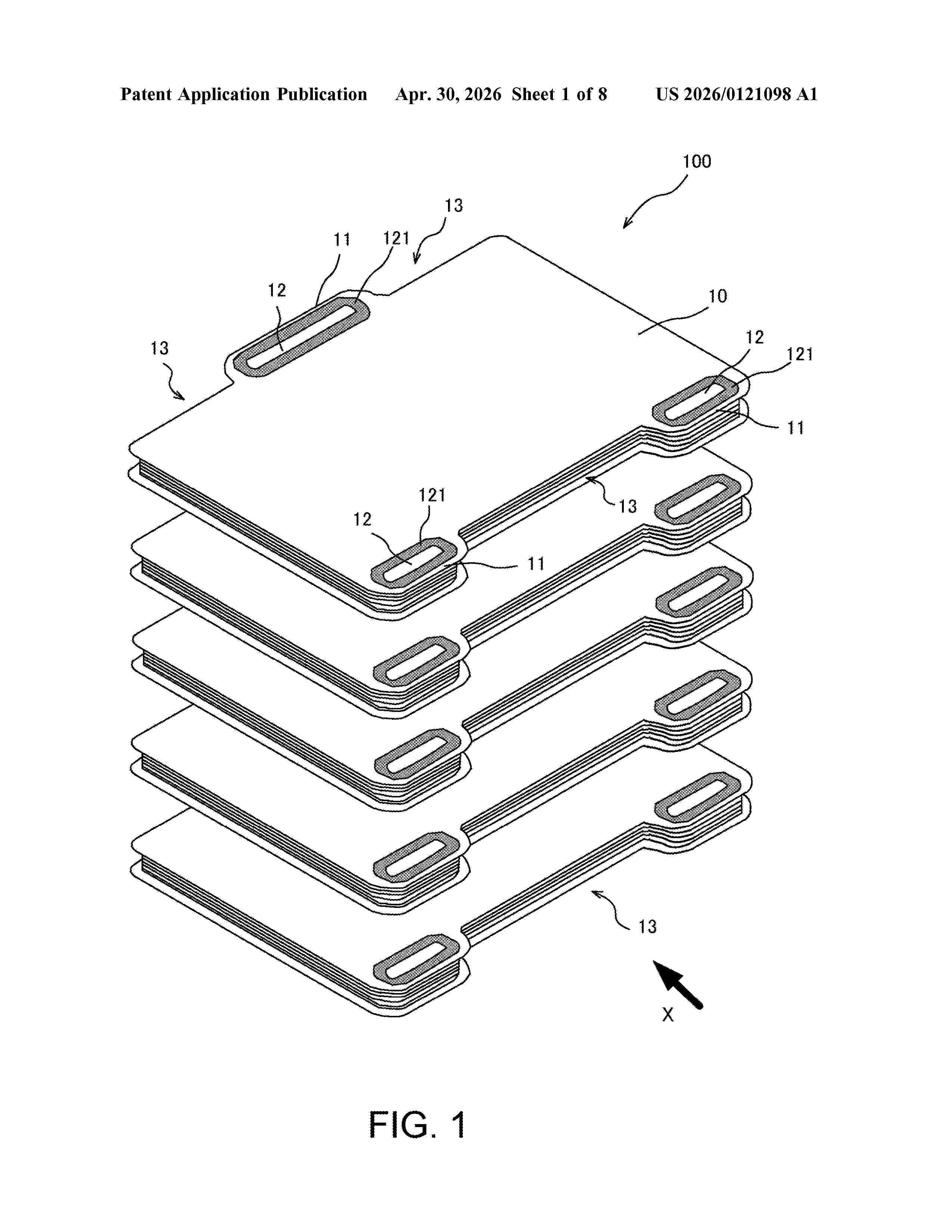
Resumen de: US20260121098A1
Provided is a solid oxide fuel cell having an open cathode structure. This solid oxide fuel cell is configured by stacking a plurality of power generating modules which is formed by stacking a plurality of cell units, and each power generating module includes a module end plate sealing a cathode reacting surface which is at least one end of a stacking direction. Further, the module end plate includes a bonding portion in which the power generating module adjacent in the stacking direction is bonded, along an outer perimeter edge.
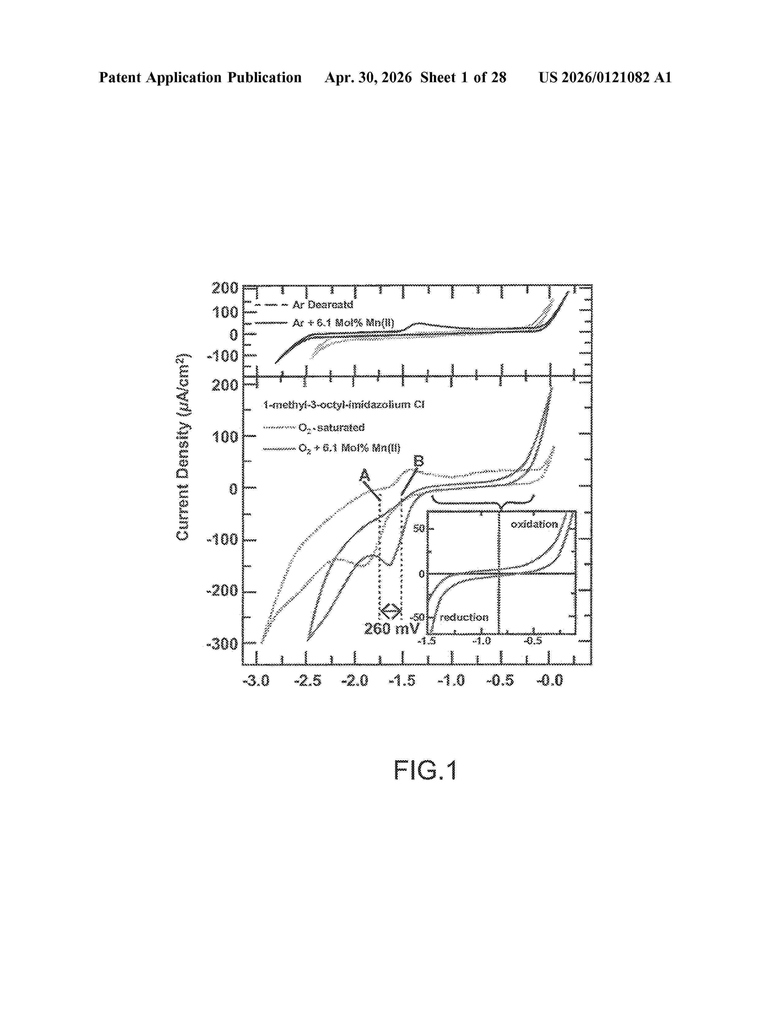
Resumen de: US20260121082A1
Systems and methods drawn to an electrochemical cell comprising a low temperature ionic liquid comprising positive ions and negative ions and a performance enhancing additive added to the low temperature ionic liquid. The additive dissolves in the ionic liquid to form cations, which are coordinated with one or more negative ions forming ion complexes. The electrochemical cell also includes an air electrode configured to absorb and reduce oxygen. The ion complexes improve oxygen reduction thermodynamics and/or kinetics relative to the ionic liquid without the additive.
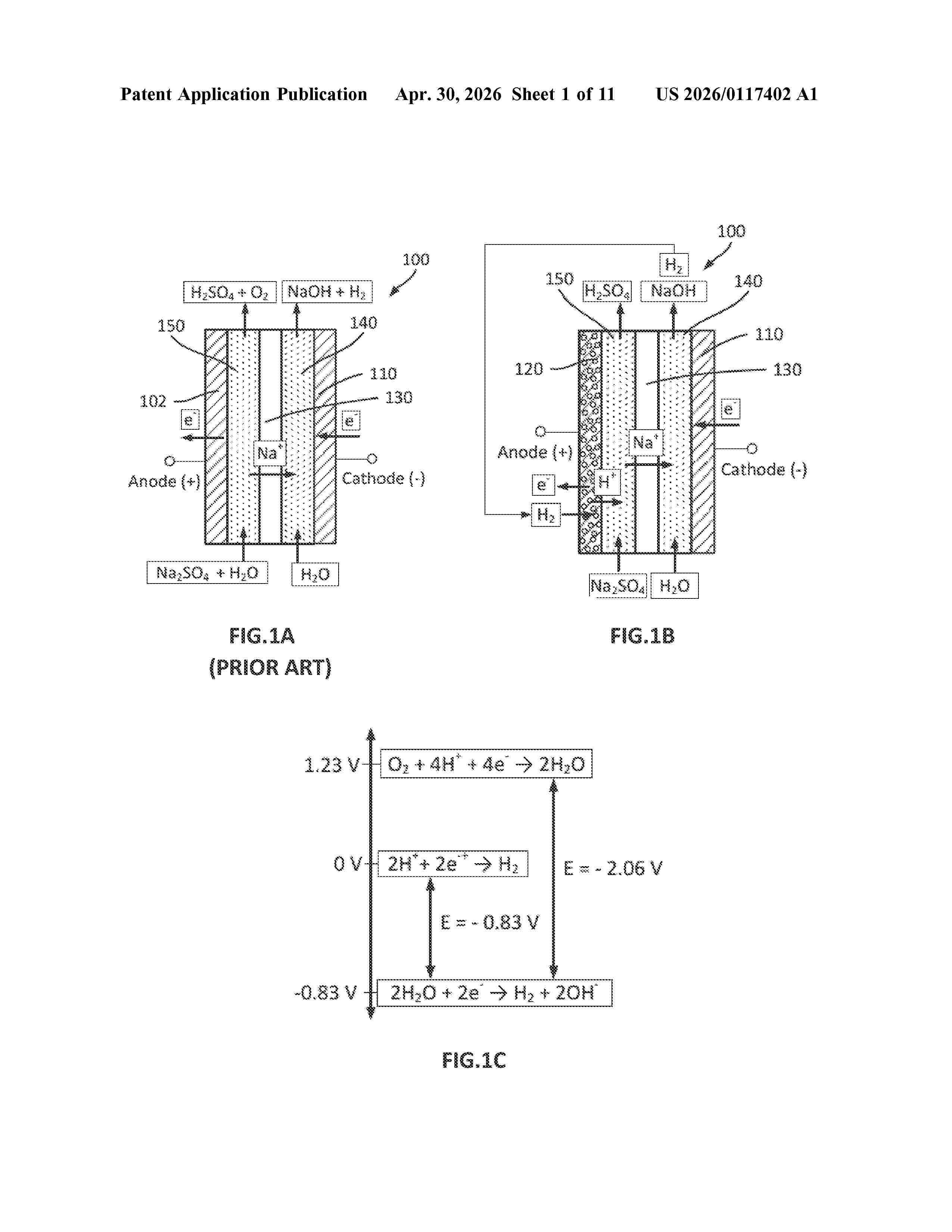
Resumen de: US20260117402A1
Described herein are gas diffusion anodes, electrolytic systems comprising such anodes, as well as methods of using such systems. A gas diffusion anode comprises a current collector, an anode porous base, an anode catalyst layer, and an anode-liquid interfacing layer. During the operation, the anode gas chamber receives hydrogen gas, which flows through the current collector into the anode porous base. The anode porous base provides uniform distribution of the hydrogen gas as well as uniform current density. The anode catalyst layer converts the hydrogen gas into protons and returns electrons, through the anode porous base, to the current collector. Protons are transported by the anode-liquid interfacing layer to an anolyte. This layer also blocks the anolyte from contacting the anode catalyst layer. The anode porous base, anode catalyst layer, and anode-liquid interfacing layer help to prevent the migration of the anolyte into an anode gas chamber.
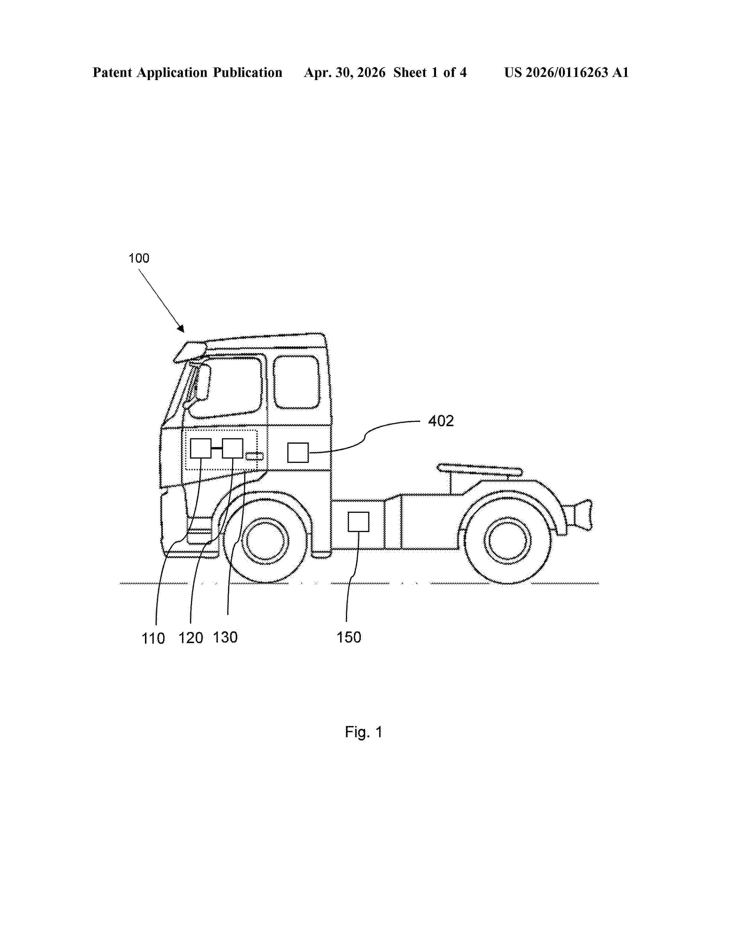
Resumen de: US20260116263A1
The present disclosure relates to a computer system and a method for controlling a power system of a vehicle. The power system includes a fuel cell system and an energy storage system including one or more batteries. The method includes: predicting a refuelling event during which the vehicle is expected to refuel a fuel tank of the fuel cell system at a fuelling station, estimating an instance for initiating a shutdown process of the fuel cell system, wherein after the estimated instance the vehicle is expected to be operated in a first operating mode, until an arrival to the fuelling station, and controlling the power system in a way such that the state-of-energy level of the energy storage system is equal to or higher than the determined state-of-energy threshold level when the vehicle reaches the estimated instance.
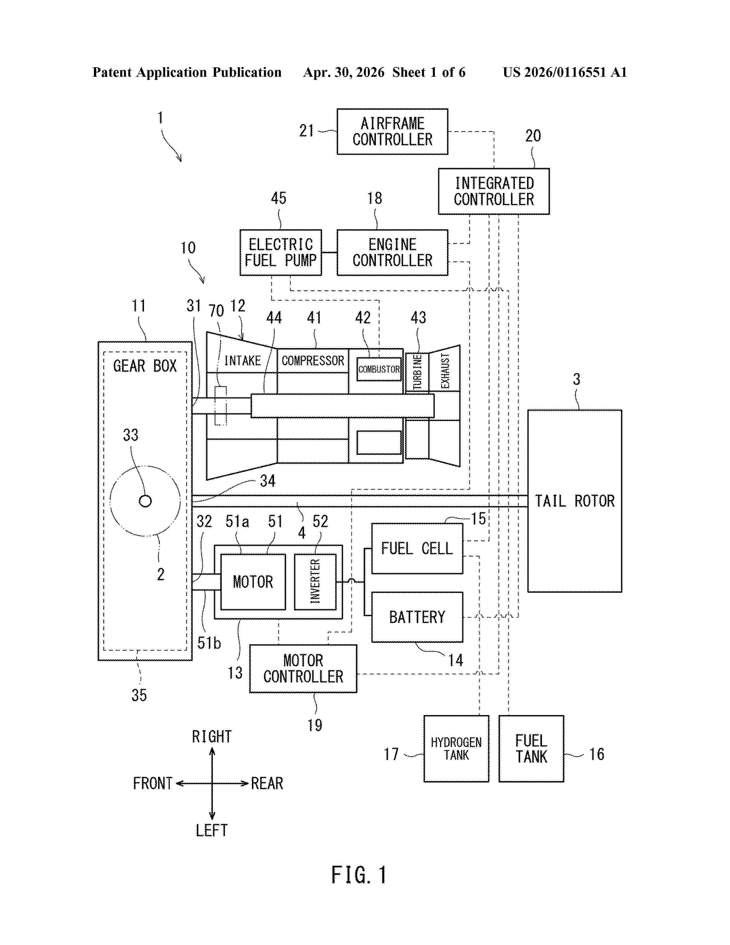
Nº publicación: US20260116551A1 30/04/2026
Solicitante:
KAWASAKI JUKOGYO KK [JP]
KAWASAKI JUKOGYO KABUSHIKI KAISHA
Resumen de: US20260116551A1
A hybrid rotor drive system includes: a gas turbine engine including a compressor, a combustor, a turbine, and a first output shaft that mechanically connects the compressor to the turbine; an electric motor including a second output shaft; and a gear box including a first input interface, a second input interface, a speed reducer that reduces speed of rotational force input from the first input interface and the second input interface, and an output interface that outputs the rotational force, which has been reduced in speed by the speed reducer, to a rotor. The first output shaft of the gas turbine engine is mechanically connected to the first input interface, and the second output shaft of the electric motor is mechanically connected to the second input interface.
 BOPI
BOPI
 Sede Electrónica