Si deseas distinguir tus productos, servicios o ambos de los de otra empresa, es posible que necesites una marca o nombre comercial. Descubre qué son, en qué consiste su procedimiento de registro y qué implica.

Información sobre los plazos de presentación de solicitudes de transformación de marcas de la Unión Europea en marca nacional española. Más información


Si tienes un nuevo dispositivo, producto o procedimiento que resuelva un problema técnico o tenga una ventaja práctica, existen distintas formas de protegerlo en España y en otros países. Descubre cómo hacerlo.

¿Tu innovación reside en la estética, la ornamentación o la apariencia de tu producto? Protégela mediante un diseño industrial. Descubre qué derechos confiere el registro y cómo realizar la tramitación.

Las indicaciones geográficas protegen el nombre de un producto originario de una zona geográfica, a la cual le debe una determinada calidad, reputación u otra característica. Descubre qué son, en qué consiste su procedimiento de registro y qué beneficios conceden.

Las patentes publicadas en todo el mundo son una valiosa fuente de información científica, técnica y comercial.

Si eres emprendedor/a o una empresa y quieres potenciar y mejorar la rentabilidad de tu negocio protegiendo de forma adecuada los activos intangibles de tu organización, en este espacio encontrarás lo necesario.


 523
resultados
523
resultados
 Última actualización
27/07/2026 [07:20:00]
Última actualización
27/07/2026 [07:20:00]


 Resultados 25 a 50 de 523

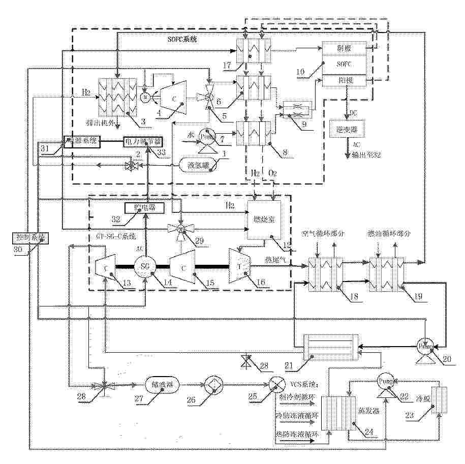
Resumen de: CN122447202A
本发明属于清洁能源的航空动力领域,提供了一种新型SOFC‑GT‑VCS混合架构循环发电系统及工作方法,通过对燃料重整生成氢气,并经过高温泵压缩提供给高温固体燃料电池;空气经过燃气涡轮发动的压气机压缩并通过热交换器加热得到高温、高压的氧气,提供给SOFC。氢气和氧气在SOFC中发生化学反应生成水蒸气,剩余的氢气输送到燃气涡轮发动机的燃烧室中与空气掺混燃烧,生成的高温高压燃气推动涡轮做功,带动发电机发电。本混合动力发电系统新架构与传统混合动力架构相比,其具有启动快、能量利用率高、功重比高的优势,系统性能优越,满足了绿色、低碳的环保要求。

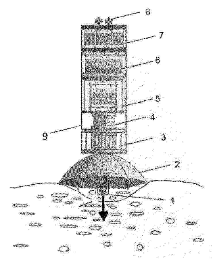
Resumen de: CN122455858A
本发明提供一种基于冷泉化能的深海原位供电装置系统及供电方法,所述深海原位供电装置系统从下至上依次设置有固定支架、伞状仿生捕获罩、微通道导流装置、双路径耦合转化装置、稳压储能一体化装置和控制装置;所述双路径转化装置包括并列设置的固体氧化物燃料电池单元和微生物电化学单元。本发明采用“仿生主动捕获+双路径能量转化+自适应稳压”一体化设计,解决气体收集难、转化效率低、稳定性差三大核心问题;将固体氧化物燃料电池单元和微生物电化学单元耦合,克服了现有的甲烷制氢耦合固体氧化物燃料电池发电系统工艺流程繁琐,系统复杂,碳排放较高、耗水量大等问题。
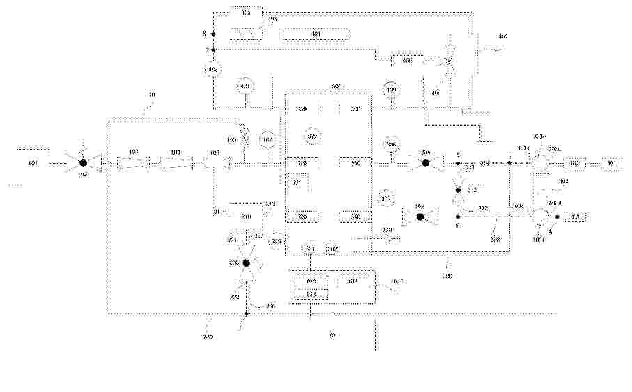
Resumen de: CN122455827A
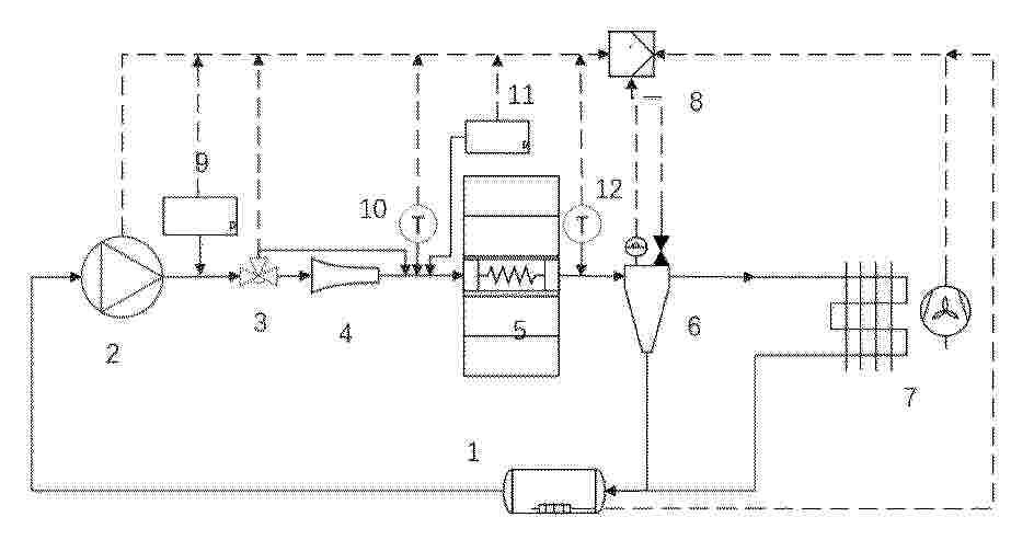
本申请涉及一种燃料电池发电系统及其控制方法,通过构建旁通通道,其第一端连接于空压机出口端与空气入口阀之间,其第二端连接于空气出口阀与涡轮端入口端之间,并在系统开机阶段和/或关机阶段控制该通路开启,形成从空压机经旁通通道返回空压机的循环空气流,直接吹扫空压机涡轮端。开机阶段,循环空气流提前建立,实现对涡轮端的预热与干燥;关机阶段,循环空气流强制清除涡轮端及管路内残留水分,避免停机后压差消失导致的水汽渗透及低温结冰,从而显著提升系统绝缘电阻,防止绝缘故障。本申请以简洁的旁通通道从根源上解决了因空压机涡轮端残留水分导致的绝缘性能下降问题,无需附加复杂外部气源或干燥装置,兼具结构紧凑性与高可靠性。
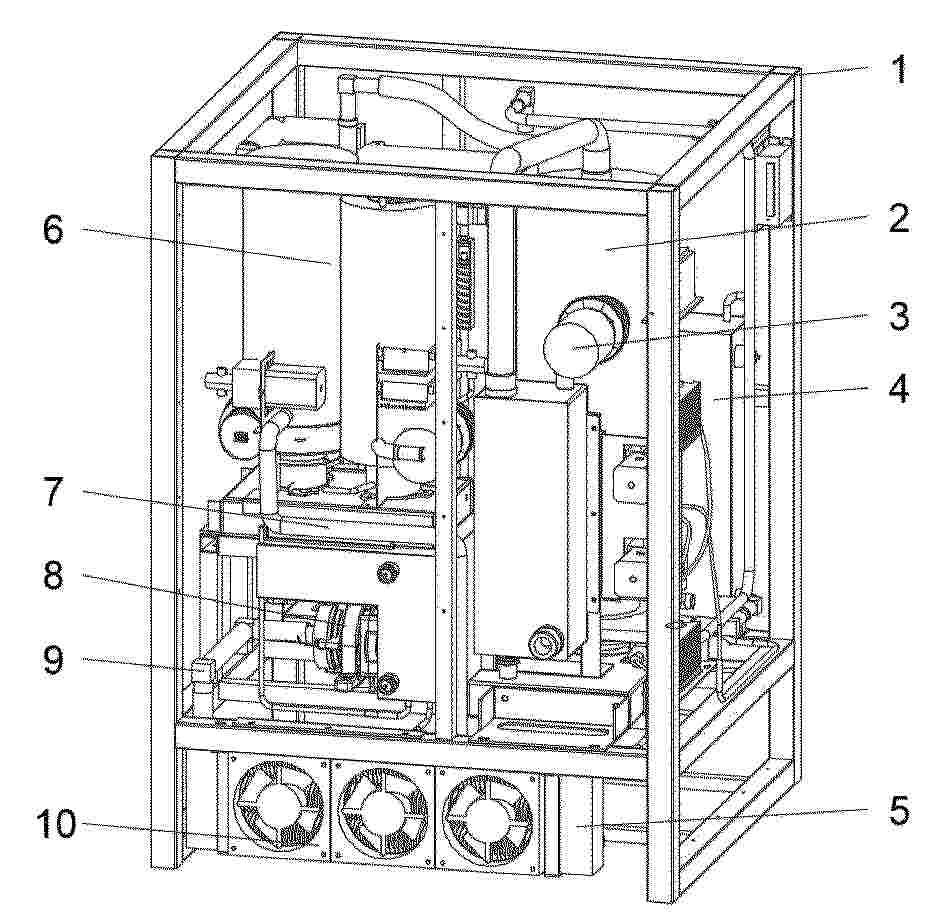
Resumen de: CN122455818A
本发明公开了一种重整制氢发电设备,包括主框架,所述主框架的内部固定安装有重整器,所述主框架的内部一侧固定安装有纯甲醇储存箱,所述纯甲醇储存箱的输出端固定连接泵送组件,所述泵送组件的输出端固定连接有燃烧炉,所述燃烧炉的循环介质输出端固定贯通有固定管。本发明中,通过设置的纯甲醇储存箱、燃烧炉、固定管、电堆、冷却组件、输出组件和泵送组件,利用纯甲醇作为燃料与循环冷却介质配合,可以提升电堆温度,当电堆温度达到设定后,可以不再对循环冷却介质进行加热,通过冷却组件对其进行散热控温,保证对电堆温度的控制效果,保证电堆的使用效果;同时整体采用集成式设计,占地面积小,利于布置。
Resumen de: CN122455833A
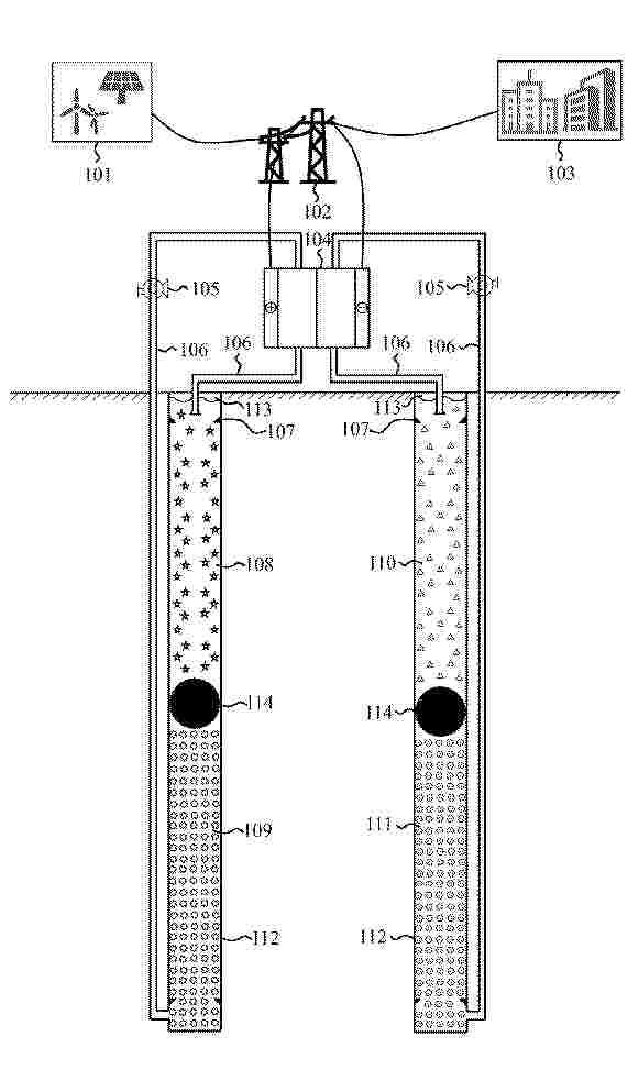
本发明公开了一种浮动活塞式的高低价态电解液分储的竖井装置,包括两个设置于地下的竖井,分别作为正极竖井和负极竖井;浮动活塞设置于竖井内部,将竖井分隔为上部储液区和下部储液区,其密度与电解液密度匹配以悬浮于电解液中并沿轴向自由移动;电堆通过传输管道与上下储液区连通;循环泵设置于传输管道上驱动电解液循环。充电时电解液从上部储液区经电堆反应后输送至下部储液区,活塞上移;放电时反向流动,活塞下移。本申请通过浮动活塞在同一竖井内实现不同价态电解液的有效隔离,仅需两个竖井即可完成分储,减少了储罐数量,降低了建设成本,同时利用地下空间减少地面占地。
Resumen de: CN122455821A
本发明公开了一种用于氢能便携电源的低温自适应产氢单元及氢能便携电源,该产氢单元包括释氢仓、输水管路和加热套;所述释氢仓包括反应仓以及环绕在所述反应仓周围的水仓夹套,释氢仓的上端设有出气口和管路安装槽,所述出气口与所述反应仓连通;所述输水管路设于所述管路安装槽内并分别接入所述反应仓和水仓夹套,输水管路上连接有水泵,用于将水仓夹套内的水输送至反应仓;所述加热套环绕包裹在所述释氢仓的外周,用于对释氢仓周围的水仓夹套进行加热。本发明可以实现产氢单元的低温防冰与融冰以及联动节能与保温。
Resumen de: CN122455822A
本发明公开了一种宽温域电堆用微通道液冷系统及控制方法,所述控制方法包括:接收实时采集的电堆温度;通过控制器判断所述电堆温度是否≥设定阈值;若否,则控制三通切换阀导通旁通支路,液体高压泵以低频运行,执行单相显热冷却;若是,则控制三通切换阀切换至雾化喷嘴支路,液体高压泵以高频运行,使冷却液雾化后进入微通道散热冷却板,利用相变潜热散热,执行局部相变冷却;其有益效果是:本发明通过采用双支路结构与智能切换机制,在低温时采用单相显热冷却以节能,在高温时自动切换至微通道局部相变冷却以强化散热,智能实现按需调节冷却强度,且冷却工质适配宽温域需求。
Resumen de: WO2025101433A1
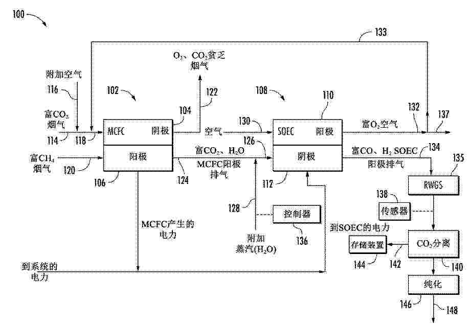
A syngas generation system includes a molten carbonate fuel cell (MCFC) including a MCFC cathode configured to receive a MCFC cathode input stream including a flue gas stream and a MCFC anode configured to output a MCFC anode exhaust stream including carbon dioxide and steam. The syngas generation system further includes a solid oxide electrolysis cell (SOEC) including an SOEC cathode and an SOEC anode. The SOEC is configured to receive, at the SOEC cathode, an SOEC cathode input stream, the SOEC cathode input stream including at least a portion of the MCFC anode exhaust stream, co-electrolyze carbon dioxide and steam in the SOEC cathode input stream, and output, from the SOEC cathode, an SOEC cathode exhaust stream including carbon monoxide and hydrogen gas.
Resumen de: WO2025094470A1
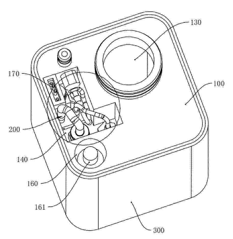
This excavator is provided with a revolving body that is rotatably provided on a traveling device, and comprises: a hydrogen tank that stores hydrogen; a fuel cell that generates power by consuming the hydrogen in the hydrogen tank; and an electric pump device that is driven by electric power generated by the fuel cell and discharges hydraulic fluid. The hydrogen tank and the electric pump device are housed in a housing space inside the revolving body, and the fuel cell is provided in the revolving body and is separated from the housing space.
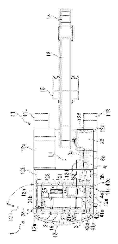
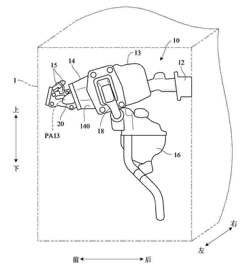
Resumen de: CN122455839A
本发明提供一种传感器安装装置,具备:流道形成构件(20),其由绝缘材料构成,形成供燃料电池用的反应气体流动的气体流道(PA13);间隔构件(30),其由导电材料构成,安装在设置于流道形成构件(20)的连接孔部(26)的端部(22);传感器(15),其安装在间隔构件(30);以及接地线(40),其安装在间隔构件30。间隔构件(30)构成为,具有设置有与连接孔部(26)的开口(25)相向的连通口(31a)的一端部(312)和设置安装有传感器(15)的传感器安装部(32)的另一端部(311),形成从一端部(312)到另一端部(311)在与反应气体的流动方向交叉的规定方向上延伸,经由连通口(31a)与气体流道(PA13)连通的封闭空间(SP1)。
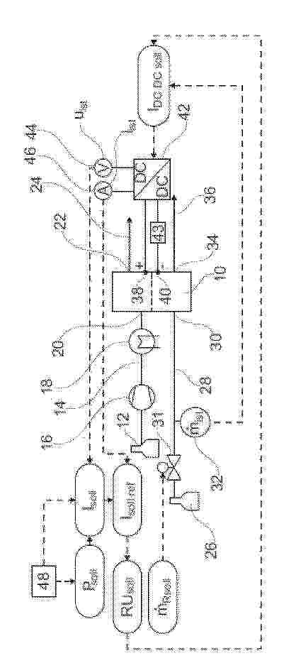
Resumen de: AT528596A4
Es wird ein Verfahren zur Regelung einer Leistung und einer Reaktantenversorgung in einem Festoxidzellensystem vorgeschlagen, bei dem - ein Soll-Strom (Isoll), auf den ein Festoxidzellenstapel (10) geregelt werden soll, entweder direkt vorgegeben wird oder aus einer Soll-Leistung (Psoll) und einer gemessenen Ist-Spannung (Uist) an einem mit dem Festoxidzellenstapel (10) verbundenen DC/DC-Wandler (42) berechnet wird, - aus dem Soll-Strom (Isoll) ein Soll-Referenzstrom (Iref,soll) bestimmt wird, der den Soll- Strom (Isoll) auf eine maximal zulässige zeitliche Änderung des Soll-Stroms (Isoll) in Abhängigkeit eines am DC/DC-Wandler (42) gemessenen Ist-Stroms (Iist) begrenzt, - aus dem Soll-Referenzstrom (Iref,soll) eine Soll-Umsatzrate (RUsoll) eines Reaktanten im Festoxidzellenstapel (10) über ein hinterlegtes Kennfeld bestimmt wird, - mittels des Faraday-Gesetzes aus dem Soll-Referenzstrom (Iref,soll) und der Soll- Umsatzrate (RUsoll) ein Soll-Reaktantendurchfluss () berechnet wird, - in Abhängigkeit des Soll-Reaktantendurchflusses () ein Durchflussregler (31) angesteuert wird, - ein Soll-Strom (IDCDC,soll) für den DC/DC-Wandler (42) aus einem über einen Durchflussmesser (32) in einer Reaktanteneinlassleitung (28) gemessenen Reaktantendurchfluss () durch Nutzung des Faraday-Gesetzes berechnet und über die Soll-Umsatzrate (RUsoll) reduziert wird.
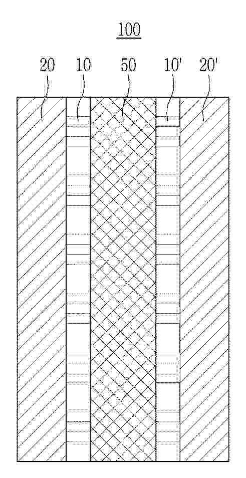
Resumen de: WO2025147075A1
The present invention relates to a membrane-electrode assembly for a fuel cell and a fuel cell comprising same and, more specifically, to a membrane-electrode assembly for a fuel cell and a fuel cell comprising same, wherein by forming a separate radical protective layer comprising fucoidan and a radical scavenger other than fucoidan between a polymer electrolyte membrane and an electrode layer, deterioration of the electrolyte membrane due to radicals can be prevented, thereby greatly improving chemical resistance.
Resumen de: WO2025142851A1
Provided is a method for recovering a fluorine-containing polymer wherein the recovered fluorine-containing polymer is resistant to swelling. The method according to the present invention for recovering a fluorine-containing polymer is a method that recovers a fluorine-containing polymer from a membrane-electrode assembly comprising: a cathode and anode having a catalyst layer that contains a catalyst and a fluorine-containing polymer having a sulfonic acid group; and, disposed between the cathode and anode, an electrolyte membrane containing a fluorine-containing polymer having a sulfonic acid group. After the membrane-electrode assembly has been brought into contact with a first solution selected from a solution A comprising only water and a solution B containing water and an alcohol, the membrane-electrode assembly is mixed with a second solution containing water and an alcohol to obtain a mixed solution containing the fluorine-containing polymer, the second solution, and insoluble matter. The insoluble matter contained in the mixed solution is removed and the fluorine-containing polymer contained in the mixed solution from which the insoluble matter has been removed is recovered.
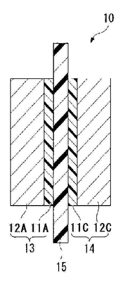
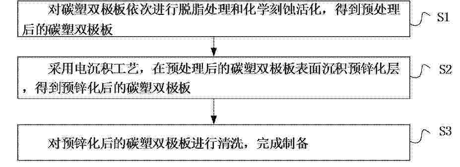
Resumen de: CN122455814A
本发明公开了一种预锌化碳塑双极板及其制备方法和锌溴液流电池,属于液流电池技术领域;该方法通过碳塑双极板预处理(脱脂+化学刻蚀)、预锌化电沉积、清洗的协同工艺,在碳塑双极板表面构建均匀、高结合力的预锌化层(厚度1‑5μm)。化学刻蚀处理可提升碳塑表面亲锌性和粗糙度,电沉积过程中匀镀剂促进锌层均匀生长。该预锌化层作为后续充放电中锌沉积的“种子层”,可引导锌定向均匀生长,显著抑制枝晶,降低界面阻抗,并减少“死锌”生成,提升电池循环寿命。
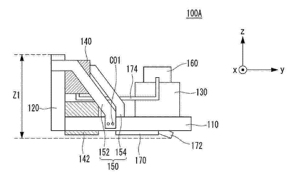
Resumen de: CN122455864A
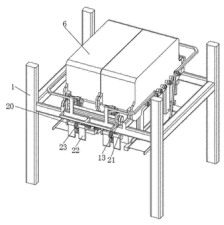
本发明涉及一种燃料电池装置,更具体地,涉及一种高度减小的燃料电池装置,其中,本发明实施例的高度减小的燃料电池装置包括:主框架;燃料电池,其设置于主框架上方;辅助框架,其与主框架结合;以及空气压缩机,其被辅助框架支承并配置于主框架上方。
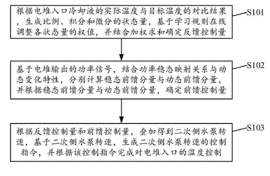
Resumen de: CN122455846A
本发明属于燃料电池热电联供系统的温度控制技术领域,公开了一种燃料电池热电联供的温度控制方法及系统,该方法包括生成比例、积分和微分的状态量,基于学习规则在线调整各状态量的权值,确定反馈控制量;基于功率稳态映射关系与动态变化特性,分别计算稳态前馈分量与动态前馈分量,并根据稳态前馈分量与动态前馈分量,确定前馈控制量;根据反馈控制量和前馈控制量,叠加得到二次侧水泵转速,基于二次侧水泵转速,生成二次侧水泵转速的控制指令,并根据该控制指令完成对电堆入口的温度控制。本发明构建了由功率前馈补偿与单神经元PID反馈控制并行组成的复合控制结构,具有动态响应快、自适应能力强、实施简便及鲁棒性强的特点。
Resumen de: CN122455855A
本发明属于电化学储能技术领域,涉及一种用于液流电池的高保酸聚苯并咪唑复合质子交换膜及其制备方法。所述复合膜以聚苯并咪唑为基体,磺化纳米填料和季铵化纳米填料均匀分散于该基体中;经酸掺杂活化处理得到高保酸聚苯并咪唑复合质子交换膜。其中,复合膜实现质子高传导位点和高保酸的双重功能,二者协同在膜内构建了质子高效传输和锁酸的纳米结构,提升液流电池的效率和循环寿命。本发明工艺简便,易于产业化,工艺条件温和可控,为解决PBI膜酸流失问题提供可行的方案。
Resumen de: CN122455840A
本申请公开了一种集成式氢燃料电堆分区精准冷却系统的控制方法,用于燃料电池技术领域,该方法包括:采集全域温度,并判定集成式氢燃料电堆的当前运行模式,根据当前运行模式调节三通调节阀和PTC电加热器,获得所需的基础冷却液温度;基于基础冷却液温度,将各分区温度与目标范围比对,通过预先配置的流量分配器向各电磁比例阀发出指令,分别调节各分区电磁比例阀的开度;持续监测实时温度和运行工况,并在满足预设切换条件时自动切换集成式氢燃料电堆的运行模式。本申请通过分区流量差异化调节,对电堆内部产热不均区域进行针对性冷却或加热,消除局部热点,缩小电堆内部温差,提升电堆性能与耐久性。
Resumen de: CN122455865A
本发明涉及全钒液流电池电堆集成领域,具体的公开了一种全钒液流电池电堆的盘管积液盘集成装置,解决了现有全钒液流电池电堆集成度差,体积较大的问题,现提出如下方案,其包括支架、电堆、吊框、盘管盒、盘管、积液盘、套块、驱动组件、摆动板,所述套块上设置有摆动组件,所述摆动组件用于在两侧套块互相靠近时,带动摆动板先靠近再远离盘管盒转动,以对盘管盒居中摆正,所述支架上两侧滑动设置有卡块,所述支架上设置有联动组件,所述联动组件用于在两侧套块互相靠近时,带动卡块对盘管盒进行安插定位。本装置能够对全钒液流电池电堆的盘管进行集成,有效减小其体积,能够更加快速的对渗液进行承接,且安装更加方便、高效与稳定。
Resumen de: CN122455842A
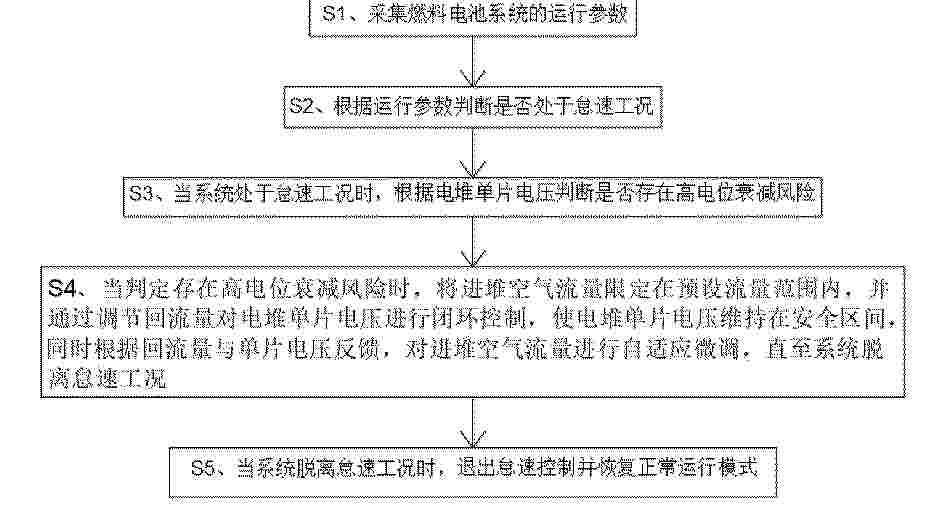
本发明公开了一种燃料电池系统怠速控制方法,具体包括如下步骤:采集燃料电池系统的运行参数;根据所述S1中的运行参数判断是否处于怠速工况;当系统处于怠速工况时,根据电堆单片电压判断是否存在高电位衰减风险;当判定存在高电位衰减风险时,将进堆空气流量限定在预设流量范围内,并通过调节回流量对电堆单片电压进行闭环控制,使电堆单片电压维持在安全区间;同时根据回流量与单片电压反馈,对进堆空气流量进行自适应微调;通过利用回流量与平均单片电压的关联逻辑,通过调节回流量间接控制反应气体浓度,无需监测氧浓度,即可将电堆单片电压稳定在0.75V‑0.85V的安全区间,有效抑制高电位对碳载体、铂基催化剂的电化学腐蚀,降低电堆不可逆衰减风险。
Resumen de: CN122455823A
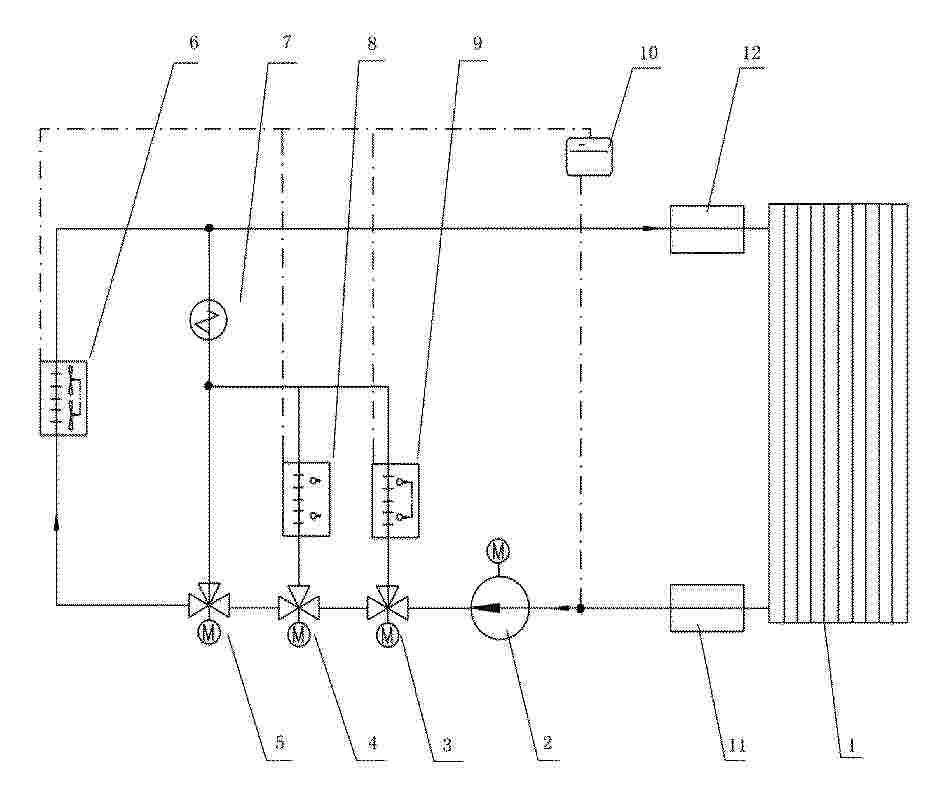
本发明涉及无人机与燃料电池技术领域,公开了一种无人机一体化吊舱用燃料电池热管理系统及控制方法,其中燃料电池热管理系统包括燃料电池、冷却液泵、第一节温器、第二节温器、第三节温器、散热系统、加热器、辐射集热系统和气动集热系统;燃料电池设有冷却液出口与冷却液入口,冷却液泵的输入端与冷却液出口相连,输出端与第一节温器、第二节温器和第三节温器的输入端依次相连;第一节温器的输出端依次经气动集热系统和加热器连通冷却液入口;第二节温器的输出端依次经辐射集热系统和加热器连通冷却液入口;第三节温器的输出端经散热系统或加热器连通冷却液入口。本发明可实现无风扇、双向能量交换以及轻量化的无人机燃料电池热管理。
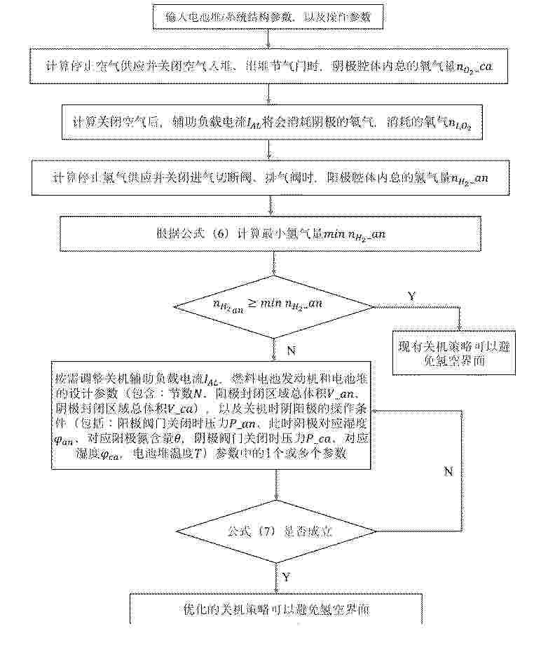
Resumen de: CN122455831A
本发明公开了一种燃料电池发动机关机方法,属于燃料电池发动机技术领域,首先确定燃料电池发动机关机流程,获取燃料电池堆的结构参数、操作条件和辅助负载电流;然后通过计算关闭空气供应以及电堆空气进出口节气门时阴极封闭区域的总氧气量和施加辅助负载后消耗的阴极氧气量,得到最小氢气量,若大于等于关闭氢气供应以及电堆氢气上下游阀门时阳极封闭区域的总氢气量,则直接执行燃料电池发动机关机流程;否则,调节燃料电池堆的结构参数、操作条件和辅助负载电流中的至少一个参数,直至满足条件,再执行燃料电池发动机关机流程,以避免本次关机过程和下次开机过程产生氢空界面,实现燃料电池发动机关机流程的优化,提升车用燃料电池发动机的耐久性。
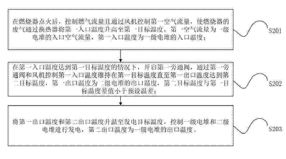
Resumen de: CN122455841A
本申请提供了一种燃料电池的控制方法、控制装置和燃料电池,该方法包括:在燃烧器点火后,控制燃气流量且通过风机控制第一空气流量,使燃烧器的废气通过换热器将第一入口温度升高至第一目标温度;然后,开启第一旁通阀,通过第一旁通阀和风机控制第一入口温度维持在第一目标温度直至第一出口温度达到第二目标温度;将第一出口温度和第二出口温度升温至发电目标温度,控制一级电堆和二级电堆进行发电,第二出口温度为一级电堆的出口温度。该方法解决了现有技术中串联结构中一级电堆升温快、降温快,二级电堆升温慢、降温慢,导致两级电堆温差过大、热应力不均,影响电池寿命的问题。
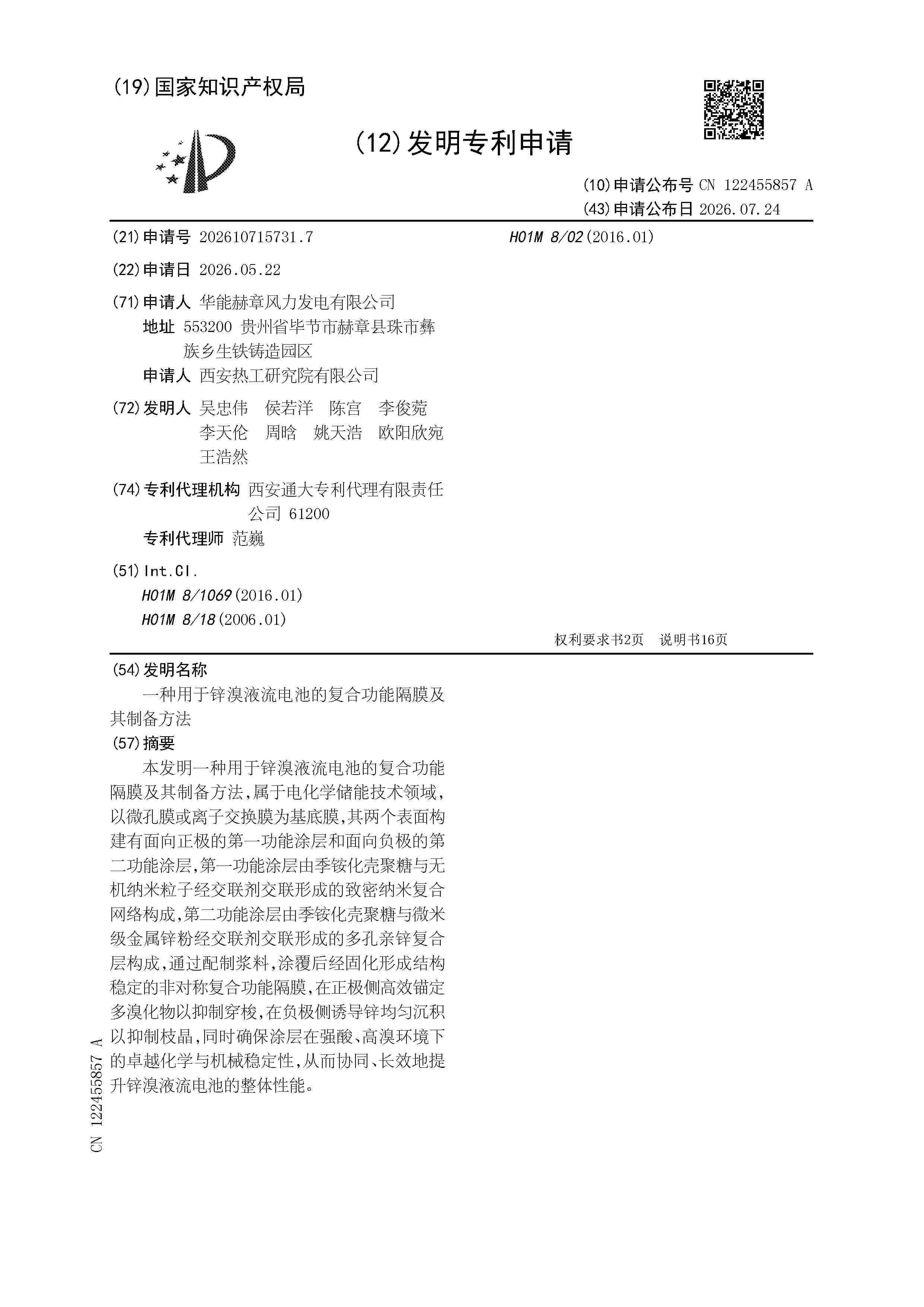
Resumen de: CN122455857A
本发明一种用于锌溴液流电池的复合功能隔膜及其制备方法,属于电化学储能技术领域,以微孔膜或离子交换膜为基底膜,其两个表面构建有面向正极的第一功能涂层和面向负极的第二功能涂层,第一功能涂层由季铵化壳聚糖与无机纳米粒子经交联剂交联形成的致密纳米复合网络构成,第二功能涂层由季铵化壳聚糖与微米级金属锌粉经交联剂交联形成的多孔亲锌复合层构成,通过配制浆料,涂覆后经固化形成结构稳定的非对称复合功能隔膜,在正极侧高效锚定多溴化物以抑制穿梭,在负极侧诱导锌均匀沉积以抑制枝晶,同时确保涂层在强酸、高溴环境下的卓越化学与机械稳定性,从而协同、长效地提升锌溴液流电池的整体性能。
Nº publicación: CN122455861A 24/07/2026
Solicitante:
深圳元及能源科技有限公司
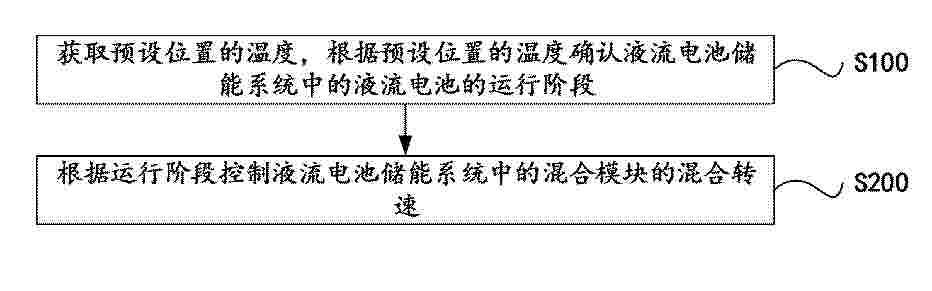
Resumen de: CN122455861A
本申请提供一种液流电池储能系统、运行控制方法以及介质,涉及液流电池控制技术领域,储能系统包括:液流电池、混合模块、多个温度检测模块以及控制模块;液流电池包括:电解液储罐以及电堆,电解液储罐用于存储电解液,且电堆与电解液储罐连通;混合模块内置于电解液储罐,混合模块用于搅动位于电解液储罐内的电解液以使电解液混合均匀;多个温度检测模块分别用于检测预设位置的温度;控制模块分别与混合模块以及多个温度检测模块连接,控制模块用于:获取预设位置的温度,根据预设位置的温度确认液流电池的运行阶段;根据运行阶段控制混合模块的混合转速。本申请在保障高效运行效率的同时,能够改善电解液储罐内的热分层现象。
 BOPI
BOPI
 Sede Electrónica