Si deseas distinguir tus productos, servicios o ambos de los de otra empresa, es posible que necesites una marca o nombre comercial. Descubre qué son, en qué consiste su procedimiento de registro y qué implica.

Información sobre los plazos de presentación de solicitudes de transformación de marcas de la Unión Europea en marca nacional española. Más información


Si tienes un nuevo dispositivo, producto o procedimiento que resuelva un problema técnico o tenga una ventaja práctica, existen distintas formas de protegerlo en España y en otros países. Descubre cómo hacerlo.

¿Tu innovación reside en la estética, la ornamentación o la apariencia de tu producto? Protégela mediante un diseño industrial. Descubre qué derechos confiere el registro y cómo realizar la tramitación.

Las indicaciones geográficas protegen el nombre de un producto originario de una zona geográfica, a la cual le debe una determinada calidad, reputación u otra característica. Descubre qué son, en qué consiste su procedimiento de registro y qué beneficios conceden.

Las patentes publicadas en todo el mundo son una valiosa fuente de información científica, técnica y comercial.

Si eres emprendedor/a o una empresa y quieres potenciar y mejorar la rentabilidad de tu negocio protegiendo de forma adecuada los activos intangibles de tu organización, en este espacio encontrarás lo necesario.


 644
resultados
644
resultados
 Última actualización
22/03/2026 [06:48:00]
Última actualización
22/03/2026 [06:48:00]


 Resultados 575 a 600 de 644

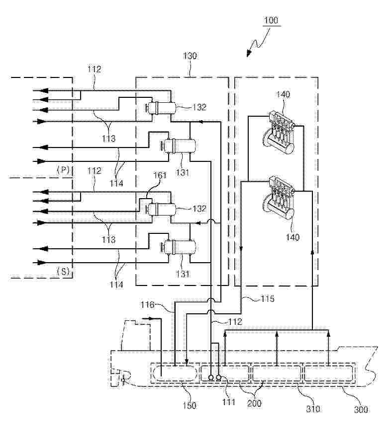
Resumen de: KR20260032679A
본 발명은 선체 내 암모니아 탱크로부터 공급되는 암모니아를 개질하는 개질부, 개질부로부터 개질된 가스를 공급받아 전력을 생산하고, 선박 추진을 위한 전력을 공급하는 연료전지부, 암모니아를 저장하고, 내부에서 발생되는 증발가스를 개질부로 공급하는 압력탱크 및 암모니아 또는 증발가스의 처리 과정에서 발생되는 폐수를 유입시켜 저장하는 빌지 홀딩 탱크를 포함하는 연료전지용 연료공급시스템을 제공한다.

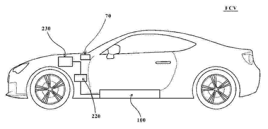
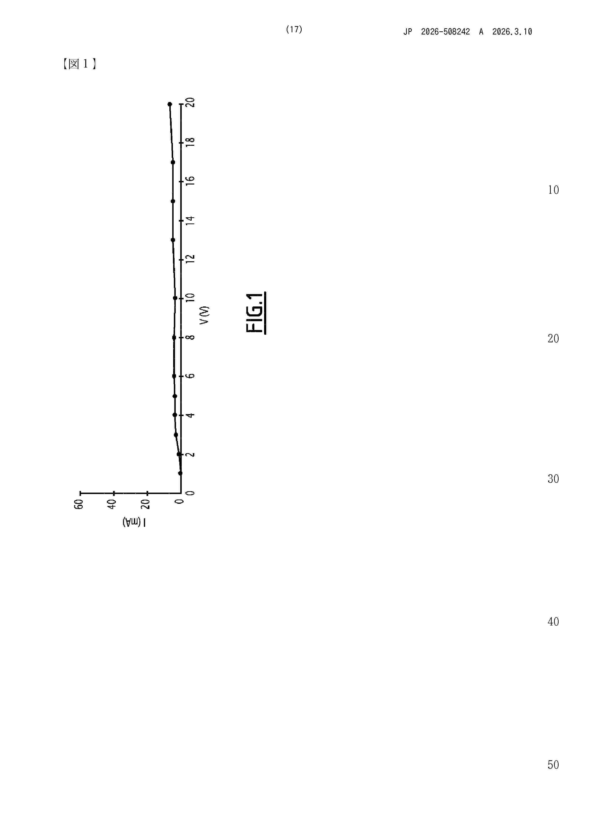
Resumen de: JP2026040823A
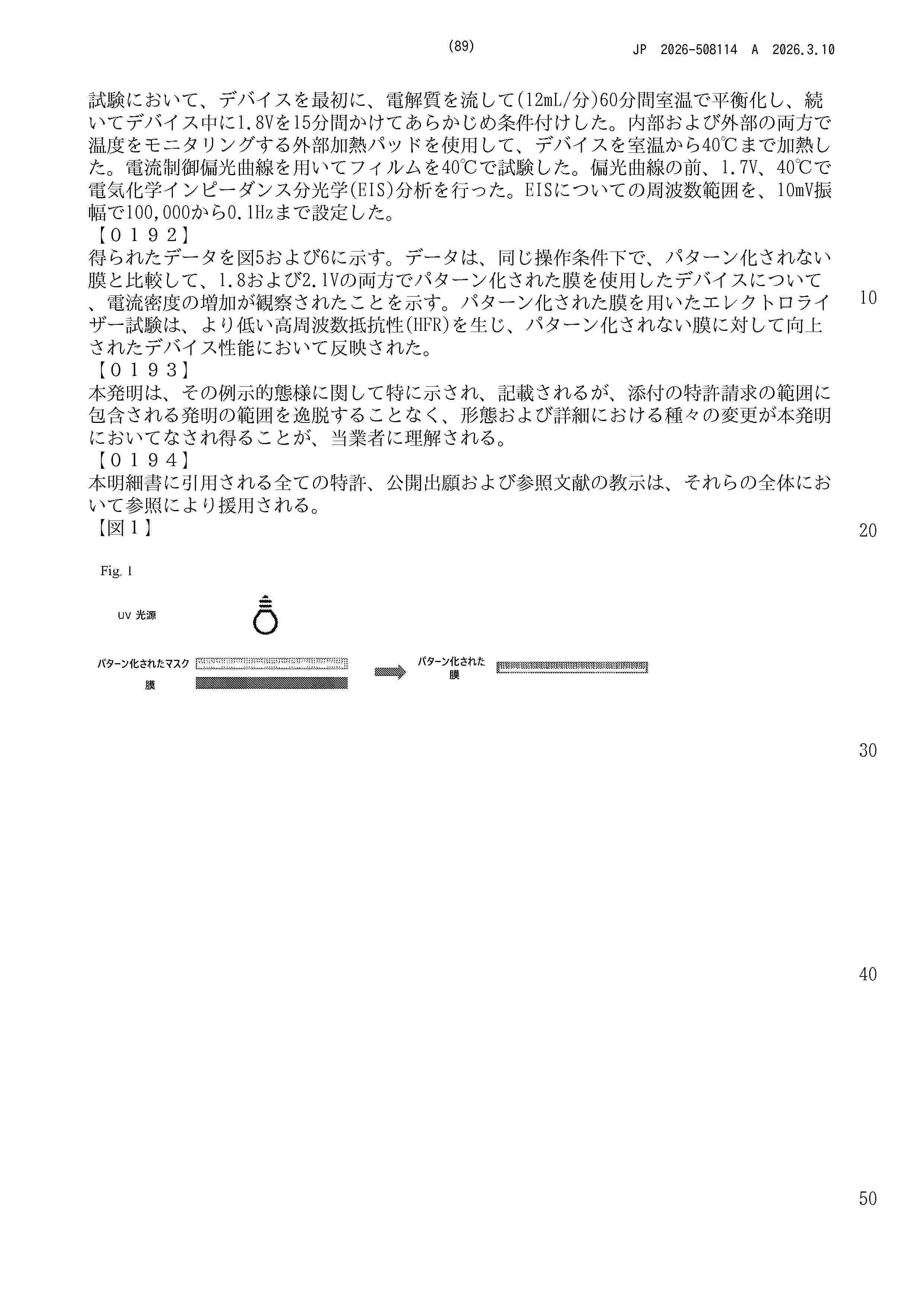
【課題】燃料電池セルを構成する触媒に対してより効率的に光を照射することで燃料電池セルの発電性能も向上可能な燃料電池システムを提供する。【解決手段】本開示の一形態における燃料電池システムは、光を透過可能な光透過型セパレータに触媒層が挟持された燃料電池セルが積層方向に複数スタックされた燃料電池スタックと、前記燃料電池スタックに前記光を照射可能な光源と、前記光源を制御する制御装置と、を含み、前記制御装置は、前記燃料電池セルの面内方向での電流分布に応じて、前記触媒層に対する前記光源からの光照射量を調整する。【選択図】 図1
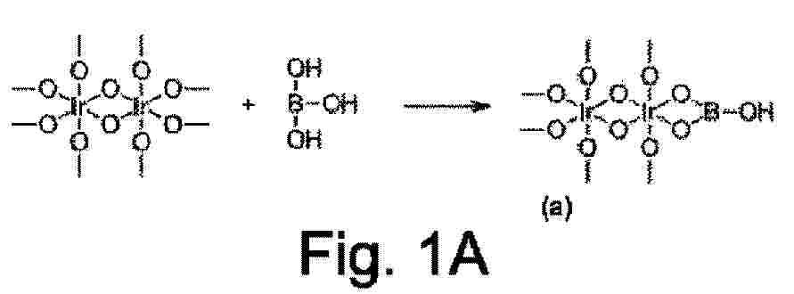
Resumen de: CN120981468A
A catalyst includes a catalyst particle including a first metal atom and an active site group attached to the first metal atom via one or more oxygen bridges. The active site group comprises a boric acid group, a metal hydroxide group or a metal oxide group. The metal hydroxide group includes a second metal atom or beryllium, and the metal oxide group includes a second metal atom. The second metal atom is different from the first metal atom and includes aluminum, gallium, indium, or bismuth.
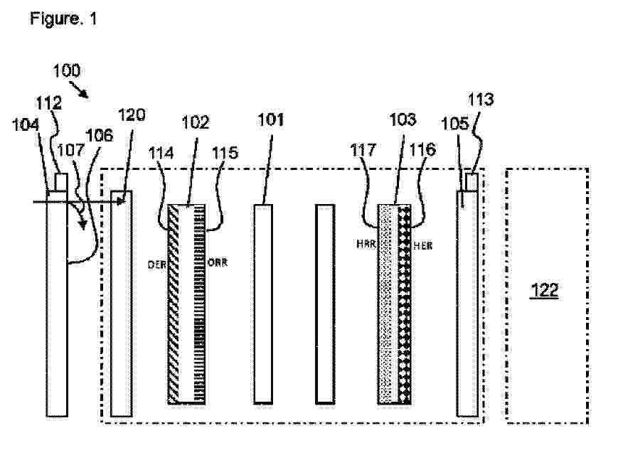
Resumen de: MX2025010333A
The present disclosure relates to fuel cells comprising fuel storage materials made from mesoporous N-doped carbon materials. The fuel storage materials comprise a proton conducting polymeric material and a composite material comprising a scaffold of coalesced (N-doped) carbon nanofoam particles, and a coating on the scaffold, said coating comprising N-doped graphitic carbon. The fuel storage materials allow fuel reserves to be stored inside the fuel cell, and are typically incorporated adjacent to an electrode to provide fuel to the electrode when the fuel cell is operating in redox mode.
Resumen de: WO2024175798A1
The invention relates to an ion-conducting membrane comprising a matrix made of a cross-linked polymer and a powder consisting of an ion-conducting material, said powder consisting of an ion-conducting material being dispersed in the continuous solid matrix and representing from 33% to 66% by volume, relative to the total volume of the ion-conducting membrane.
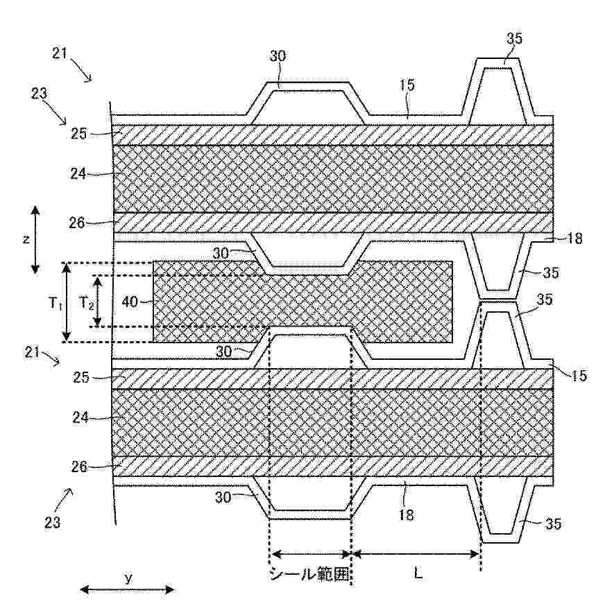
Resumen de: US20260058170A1
A fuel cell stack includes a plurality of fuel cells and an inter-cell sealing material disposed between the fuel cells. The fuel cells include a rib protruding in a direction of adjacent fuel cells. The rib is located outside the sealing range of the inter-sealing material. The rib has such a height that the compressibility of the inter-cell sealing material is 20% or more and 70% or less in the sealing range.
Resumen de: CN120604365A
Systems, methods, and products are described that involve a set of calender rollers positioned adjacent to a set of embossing or cutting or combining rollers, but without a heating unit disposed therebetween. The produced embossed or cut graphite-based webs with bipolar plate structures can be manufactured at reduced cost and with improved quality.
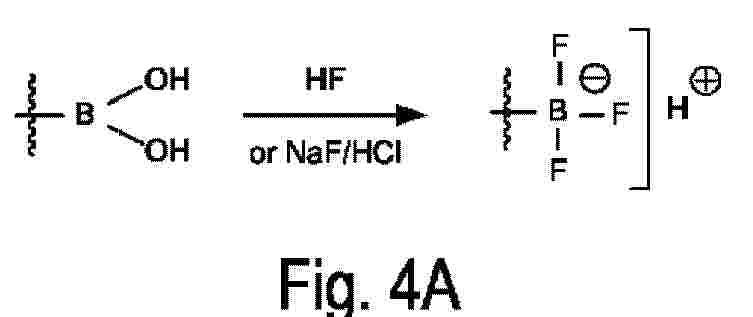
Resumen de: CN120882727A
A method of making a tetra-coordinated boric acid functionalized polymer molecule includes reacting a pendant boric acid group of the boric acid functionalized polymer molecule with a fluoride reagent and/or a compound of the general formula HX, wherein HX is Bronsted-loreoic acid. A tetra-coordinated boric acid functionalized polymer molecule comprises a backbone and a tetra-coordinated boric acid group attached to the backbone. The general formula of the tetracoordinated boric acid group is-BFmXn (OH) (3-m-n), and B has four covalent bonds and is covalently bonded to the main chain, the side chain or the side group of the polymer; m and n are each independently 0, 1, 2, or 3; the sum of m + n is 1, 2, or 3; and X is an anion other than a fluorine ion.
Resumen de: AU2024214099A1
The present disclosure relates to patterned anion exchange membranes comprising cross-linked segments and non-crosslinked segments. The present disclosure further relates to methods of manufacturing of the patterned anion exchange membranes, as well as electrochemical devices comprising the disclosed patterned anion exchange membranes.
Resumen de: US20260058169A1
A separator for a fuel cell includes a plate-shaped body including multiple ribs extending in parallel. The ribs protrude from the body to come into contact with a gas diffusion layer of a membrane electrode gas diffusion layer assembly. Spaces between the ribs and between the body and the gas diffusion layer form passages through which gas is supplied to and discharged from the membrane electrode gas diffusion layer assembly. The ribs include dividing portions that divide the passages extending in parallel. Each dividing portion divides the corresponding passage into sections on upstream and downstream sides in a gas flow direction. The positions of the dividing portions in the gas flow direction of the passages are set to be different between adjacent ones of the passages in a direction in which the ribs are arranged in parallel.
Resumen de: KR20230143128A
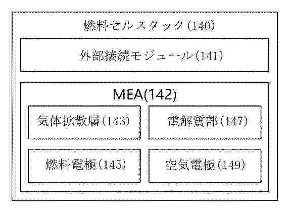
A fuel cell stack for capturing carbon in the atmosphere according to an embodiment of the present invention comprises: a fuel electrode to which a metal fuel in a liquid or gas state is supplied; an air electrode to which a gas mixture including carbon dioxide and oxygen is supplied; and an electrolyte unit including an electrolyte that transmits metal ions generated by the redox of the metal fuel between the fuel electrode and the air electrode, wherein the air electrode may generate a carbon-captured product including a carbon component based on the redox of the gas mixture. Besides, various embodiments for capturing carbon and generating energy are disclosed. Costs for capturing carbon can be saved.
Resumen de: CN223986576U
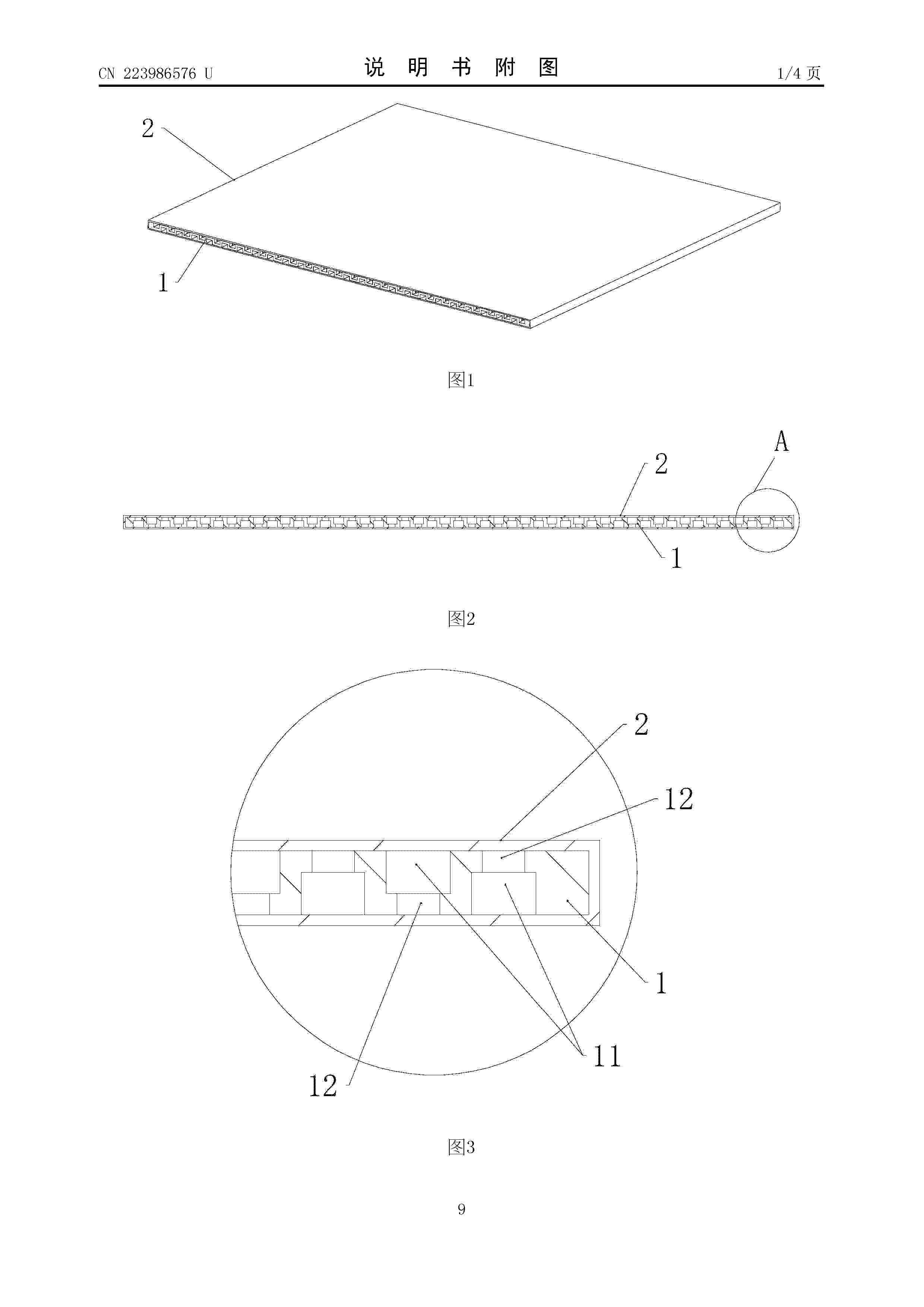
本申请公开了一种一体化电极及液流电池,一体化电极包括导流基板和包裹于导流基板外表面的反应活性电极材料,反应活性电极材料为柔性结构,导流基板包括交替布置的凹形区和凸形区,凹形区的内侧和凸形区的背侧形成电解液流道,电解液流道具有曝露于反应活性电极材料外侧的电解液进口和电解液出口,电解液流道的流道壁上设有用于将电解液朝向反应活性电极材料导流的导流孔,反应活性电极材料与导流基板保持相对固定,形成电解液流通与电化学反应的一体化结构。本申请的方案既保证了电解液的高效流动,又提供了稳定的反应界面,降低了浓差极化,提升电池效率,同时,导流基板便于机械夹爪抓取,支持全自动化电堆装配。
Resumen de: CN223986577U
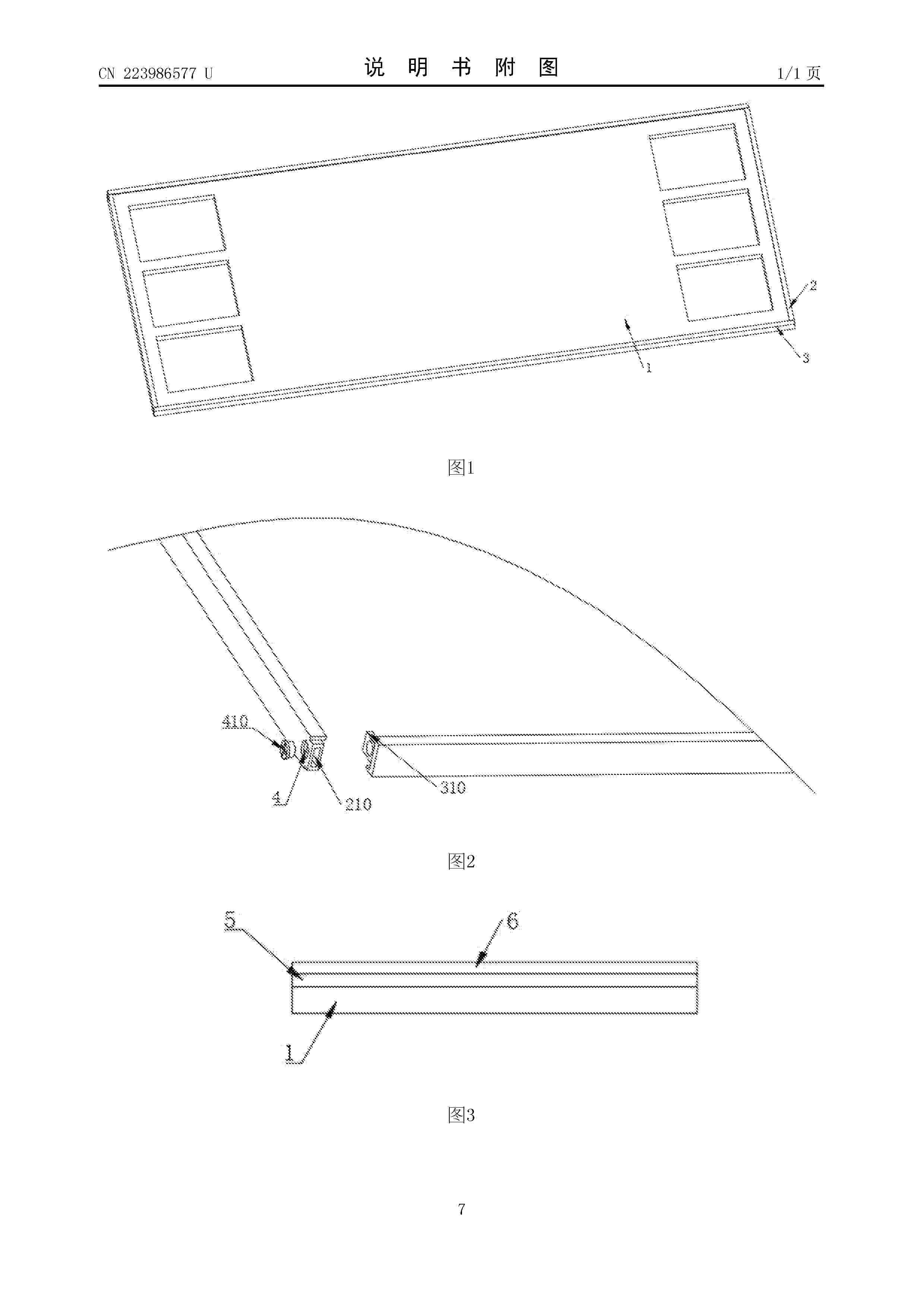
本实用新型涉及电池双极板技术领域,且公开了一种高耐腐蚀性能的金属双极板,包括金属双极板本体:所述金属双极板本体的两长侧边均贴合有包覆板二,所述金属双极板本体的两短侧边均贴合有包覆板一。该种高耐腐蚀性能的金属双极板,能够有效的保护金属双极板本体的侧边,防止出现磨损和折损的情况,同时能够对金属双极板本体进行一定程度上的密封,且侧边防护结构均采用碳纤维材料构成,不影响金属双极板本体正常工作,同时碳纤维材料构成的侧边防护其结构强度高,化学特性优异,使用寿命长,而导电涂层和碳基涂层的结合,能够加强碳基涂层与金属双极板本体表面连接强度,避免出现碳基涂层脱落的情况,同时能够提高金属双极板本体的耐腐蚀性能。
Resumen de: CN223986580U
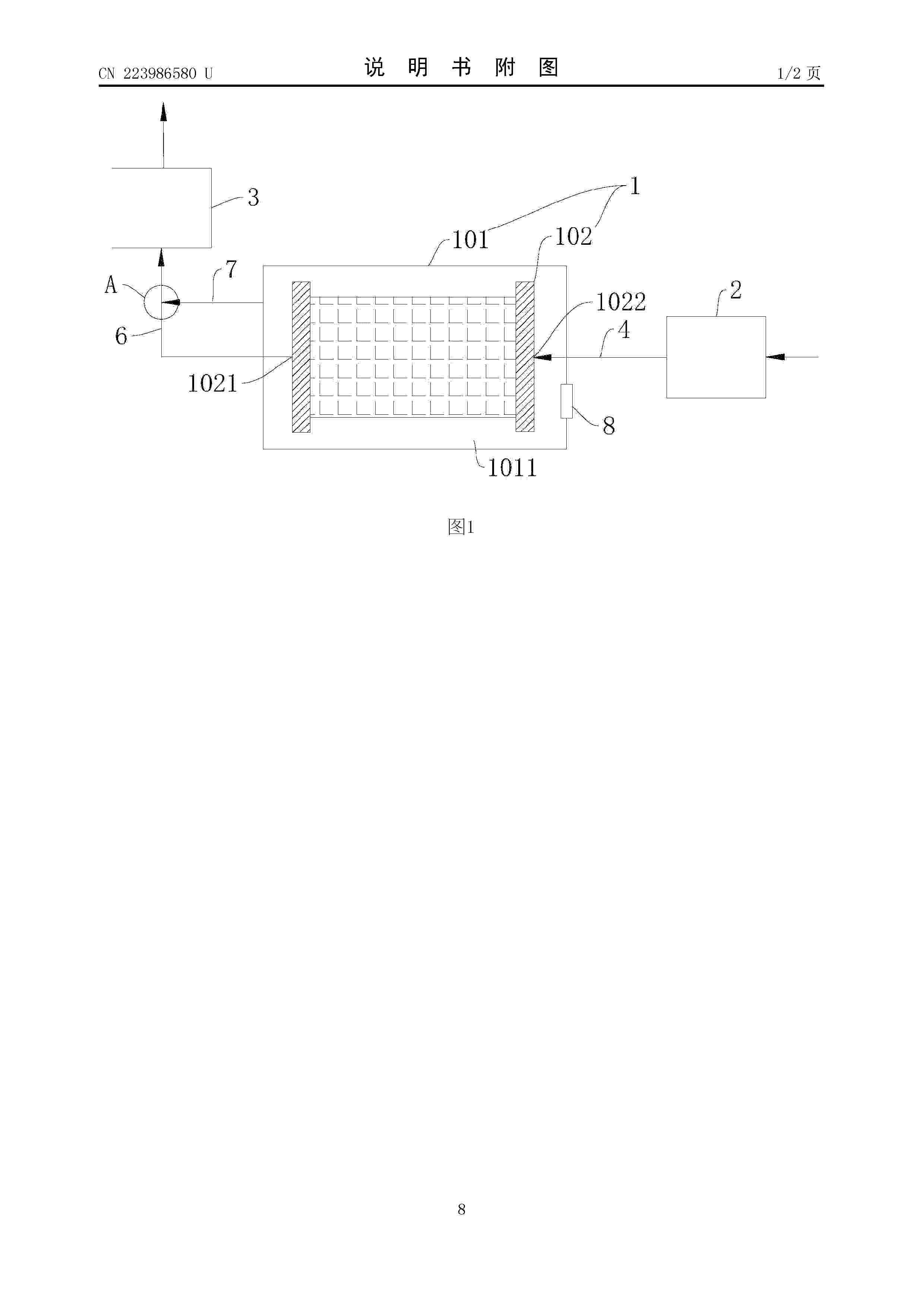
本实用新型提供了一种燃料电池堆通风系统和车辆,本实用新型的燃料电池堆通风系统涉及燃料电池技术领域,其包括为堆芯提供高压气体的进气部、将堆芯中气体排出的排气部,以及出气支管,其中,排气部包括与堆芯的排气口连通的排气管路,出气支管的一端与排气管路连通,另一端与燃料电池堆壳体的容纳腔连通。本实用新型所述的燃料电池堆通风系统,通过设置出气支管,在排气管路排气的过程中,容纳腔内的氢气可通过出气支管经排气管路一起排出,可防止氢气聚集并降低因此而引发的风险,可省去向容纳腔内吹气以对容纳腔内气体进行吹扫的吹扫进气管路,从而减少零部件数量、减轻重量、降低成本,且不影响堆芯通风系统的通风效率。
Resumen de: CN223986578U
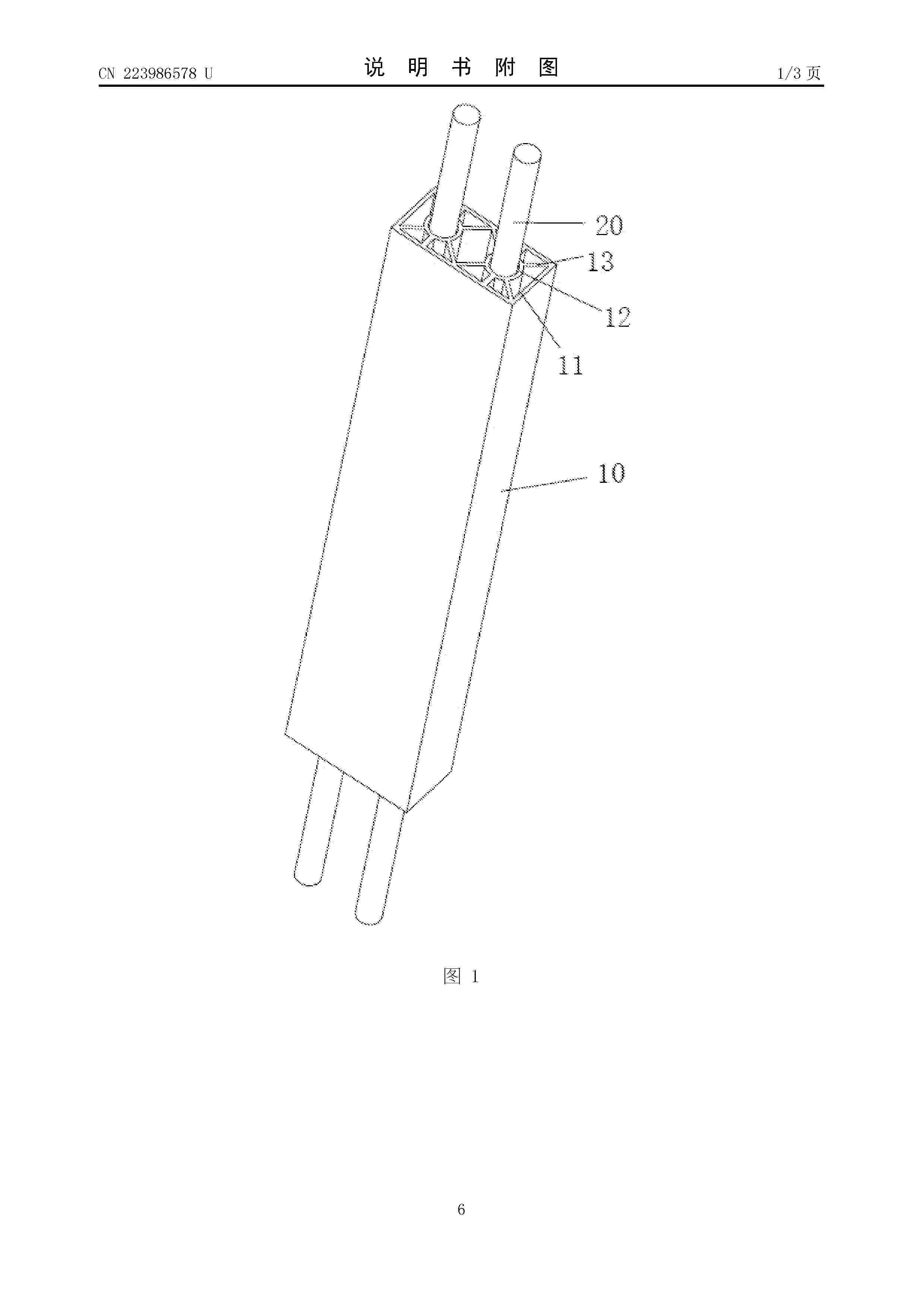
本实用新型公开了一种液流电池电堆及其支撑锁合组件,其中,支撑锁合组件包括:支撑杆体,支撑杆体包括:支撑套、以及至少一个支撑筒,所述支撑筒通过若干支撑片与所述支撑套相连接,且所述支撑杆体的两端分别与电池电堆两侧的端板内侧相抵触;以及,插接于所述支撑筒内的连接螺杆,所述连接螺杆与所述支撑套紧密配合,且所述螺杆与设置在端板上的连接孔相适配以用于锁紧电池电堆。通过支撑杆体的两端与两端板相抵触,从而实现对端板的支撑,减少端板在紧固时发生弯曲变形,进而有利于提升电堆整体的密封性,支撑杆体的内侧面与电堆的内构件相接触,从而在搬运时对内构件进行支撑,减少在搬运过程中内构件产生位移,避免对电堆造成破坏性伤害。
Resumen de: CN121642003A
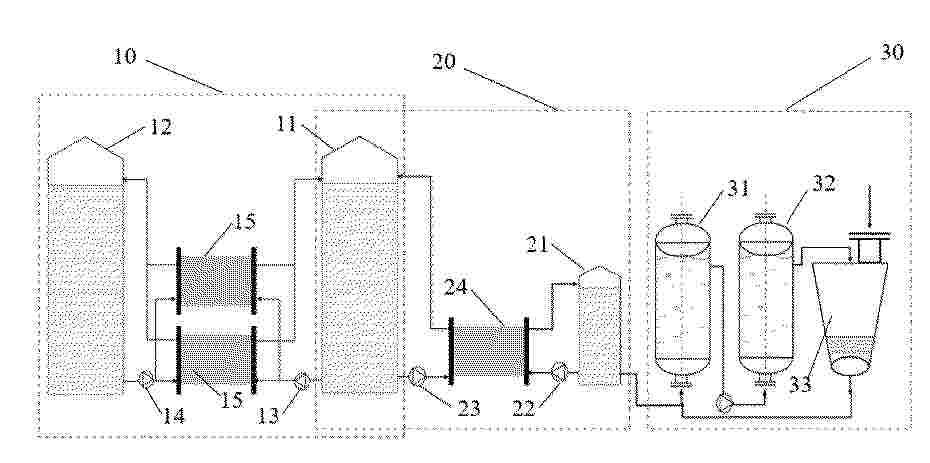
本发明公开了一种铁铬液流电池在线容量恢复的系统及方法,属于液流电池技术领域,包括依次相连通的储能主系统、再平衡系统和离子恢复系统,所述储能主系统包含正极电解液和负极电解液,所述再平衡系统包含再平衡电解液,用于将所述储能主系统中失衡的所述正极电解液中Fe3+还原,所述离子恢复系统包含还原性气体,用于将所述再平衡电解液中失衡的离子价态恢复。本发明采用的系统和方法,操作简单,成本低廉,通过离子恢复系统中还原气体以化学方法来还原失衡的再平衡电解液,使再平衡电解液能够维持一定的价态离子平衡浓度,使得储能系统中正极电解液能够在线容量恢复,缩短容量恢复时间,保证电池的使用性能。
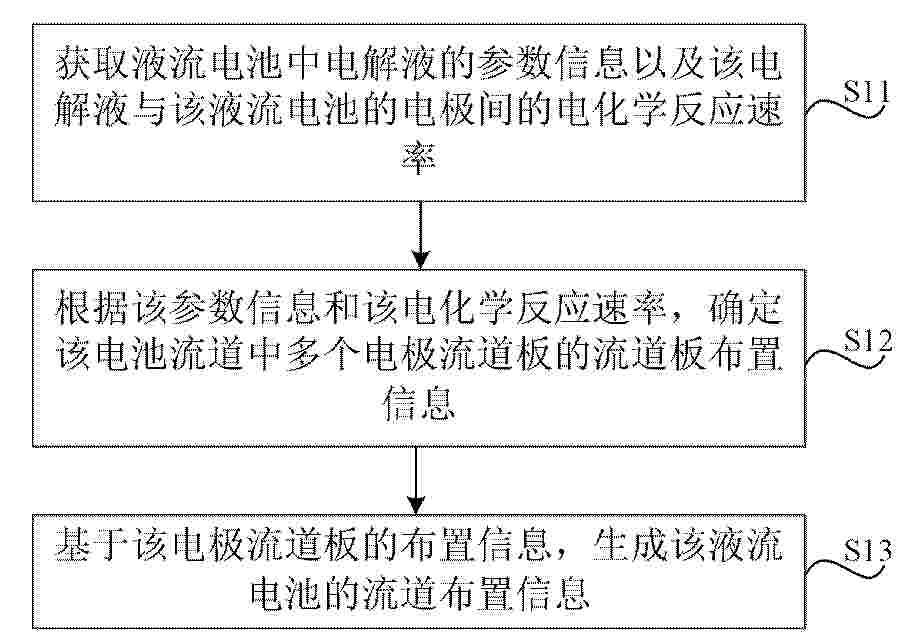
Resumen de: CN121642009A
本公开涉及一种液流电池流道的布置方法、装置、液流电池及电池堆,该方法包括:获取液流电池中电解液的参数信息以及该电解液与该液流电池的电极间的电化学反应速率,并根据该参数信息和该电化学反应速率,确定该电池流道中多个电极流道板的流道板布置信息,并基于该电极流道板的布置信息,生成该液流电池的流道布置信息。
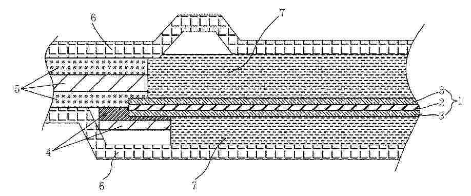
Resumen de: CN121642014A
本发明公开了一种单电池封装结构及其制备方法,涉及单电池技术领域,膜电极包括质子交换膜和位于所述质子交换膜两侧的催化剂层,一侧的所述催化剂层与单面胶边框的热熔胶层粘结,另一侧的所述催化剂层搭接在双面胶边框上,所述单面胶边框的热熔胶层粘结所述催化剂层后超出部分与所述双面胶边框粘结,所述双面热熔胶边框的上下两侧分别设有极板,所述膜电极和两所述极板之间形成气体扩散层,得到的单电池密封效果好,不易发生反应介质泄露。
Resumen de: WO2025042412A1
An anion-conducting polymeric membrane can include vinylbenzyl-Rs vinylbenzyl-Rx and styrene. In some embodiments, Rs is a tetra methylimidazolium, and Rs is a positively changed amine. In some embodiments, the total weight of the vinylbenzyl-Rs groups is greater than 20% of the total weight of the membrane.
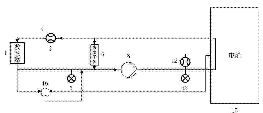
Resumen de: CN121642022A
本发明公开了一种燃料电池发动机冷却系统、车辆和监测方法,涉及车辆技术领域。系统,包括:电堆、散热器、水泵、膨胀水箱、去离子器,及多个流量计和多个压力传感器;电堆、散热器、水泵依次连接,构成第一回路;电堆、去离子器、水泵依次连接,构成第二回路;膨胀水箱的补水口连接在第一回路上,膨胀水箱的第一回水口连接在第二回路上,膨胀水箱的第二回水口连接在电堆的冷却液出口连接的管段上;多个流量计包括散热器入口处的第一流量计和电堆冷却液进口处的第二流量计,多个压力传感器包括设散热器出口处的第一压力传感器和电堆冷却液进口处的第二压力传感器。通过流量和压力监测,可降低低温下燃料电池发动机启动失败或反应不达标的概率。
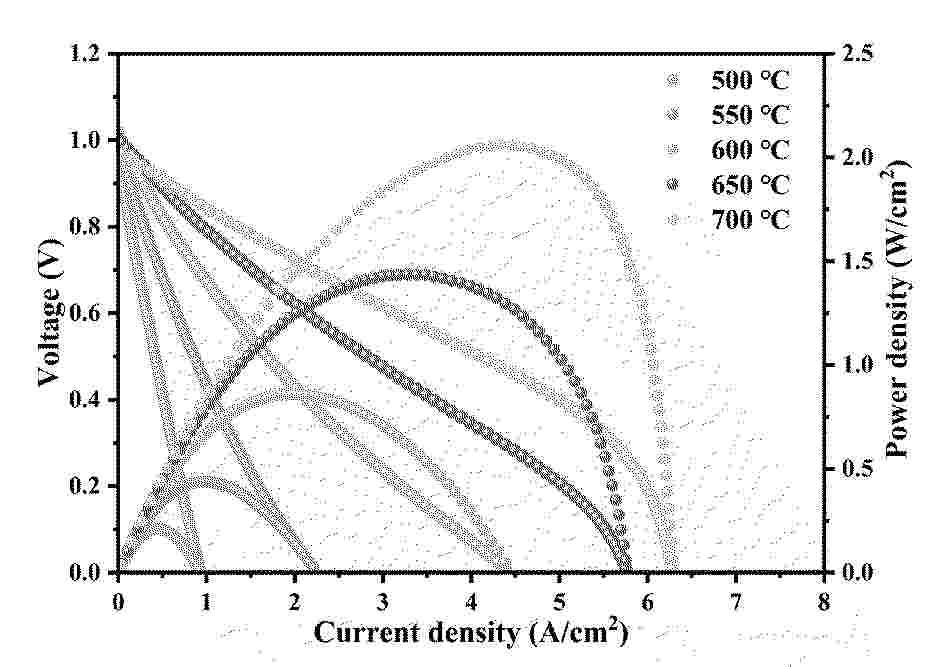
Resumen de: CN121641994A
本发明公开了一种海胆状尖晶石电极材料在固体氧化物燃料电池中的应用,本发明中SOFC氧电极材料为海胆状NiCo2O4尖晶石,通过水热法制备得到。本发明中的海胆状尖晶石通过电流极化诱导方法自组装到YSZ电解质表面,不经过高温烧结过程,海胆状尖晶石电极可以保持良好的纳米结构和高比表面积,基于该海胆状尖晶石氧电极的SOFC取得了优异的电化学性能,在700℃的工作温度下,最大输出功率可达2.06W/cm2,欧姆阻抗为0.053Ωcm2,极化阻抗为0.077Ωcm2,且表现出优异的长期稳定性。
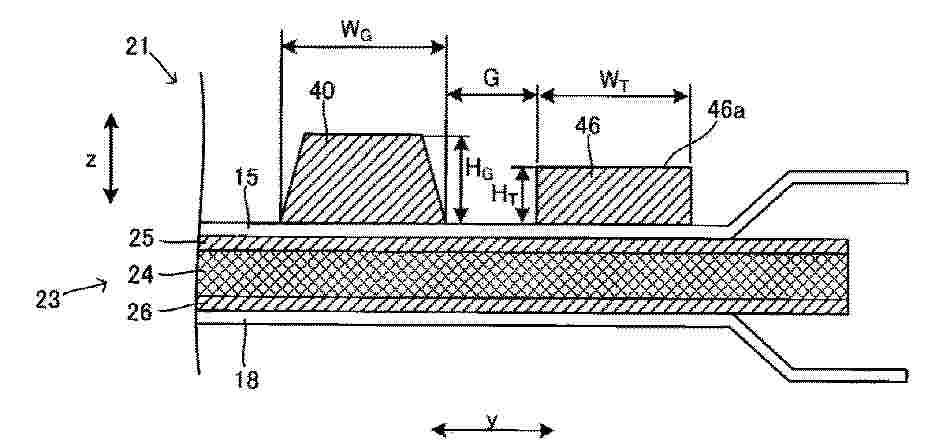
Resumen de: CN121642011A
一种燃料电池单元,在一对隔板之间具有电极体,其中,具有:垫圈,配置于隔板的、与电极体所配置的一侧的面处于相反侧的面;和凸部件,配置于一对隔板中的一个隔板的、与电极体所配置的一侧的面处于相反侧的面,凸部件配置于比垫圈靠隔板的外周缘侧的位置,凸部件的高度比垫圈的高度小。
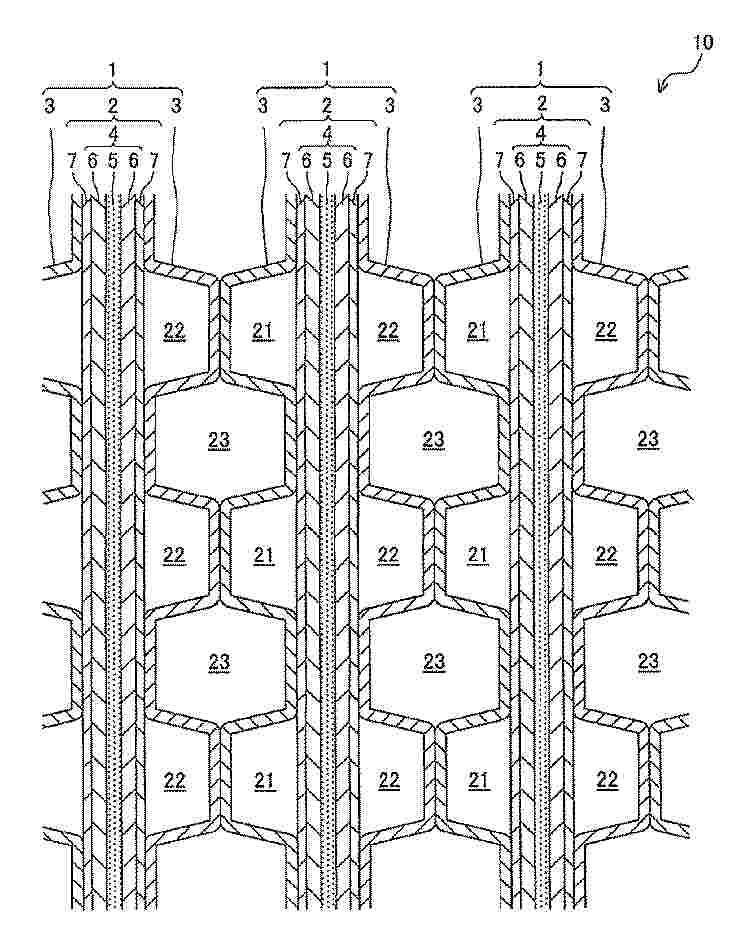
Resumen de: CN121642051A
本实施方式为一种膜电极接合体,其具有:固体高分子电解质膜;阳极催化剂层,其配置于所述固体高分子电解质膜的一个面上;及阴极催化剂层,其配置于所述固体高分子电解质膜的另一个面上,其中,所述膜电极接合体包含选自铈离子及锰离子中的金属离子及能够与所述金属离子形成包合化合物的主体化合物,所述阴极催化剂层包含电极催化剂、粘合剂及有机含氮化合物,所述电极催化剂包含金属负载催化剂,所述金属负载催化剂包含催化剂金属及负载该催化剂金属的载体,所述有机含氮化合物为选自由规定的式(1)的化合物、式(2)的化合物及式(3)的化合物组成的组中的至少1种化合物或包含所述至少1种化合物作为聚合成分的聚合物。
Nº publicación: CN121641998A 10/03/2026
Solicitante:
昆明理工大学
Resumen de: CN121641998A
本发明公开了一种钯过渡金属合金负载生物质碳材料的制备方法及其应用,其特征在于,制备方法包括:采用柳絮作为碳源,以氯钯酸和金属盐为原料,采用微波还原法合成材料,制备钯过渡金属合金负载生物质碳材料;所述的钯过渡金属合金负载生物质碳材料用于制成工作电极,能够应用于质子交换膜燃料电池,葡萄糖生物电池。本发明选用常见的普通柳絮作为碳源,采用廉价的过渡金属作为原材料,降低了成本的同时采用的合成方法简单,工艺稳定可靠,具有一定的可操作性,同时本发明制得的催化剂具有明显优异的乙醇和葡萄糖氧化电催化活性。
 BOPI
BOPI
 Sede Electrónica