Si deseas distinguir tus productos, servicios o ambos de los de otra empresa, es posible que necesites una marca o nombre comercial. Descubre qué son, en qué consiste su procedimiento de registro y qué implica.

Información sobre los plazos de presentación de solicitudes de transformación de marcas de la Unión Europea en marca nacional española. Más información


Si tienes un nuevo dispositivo, producto o procedimiento que resuelva un problema técnico o tenga una ventaja práctica, existen distintas formas de protegerlo en España y en otros países. Descubre cómo hacerlo.

¿Tu innovación reside en la estética, la ornamentación o la apariencia de tu producto? Protégela mediante un diseño industrial. Descubre qué derechos confiere el registro y cómo realizar la tramitación.

Las indicaciones geográficas protegen el nombre de un producto originario de una zona geográfica, a la cual le debe una determinada calidad, reputación u otra característica. Descubre qué son, en qué consiste su procedimiento de registro y qué beneficios conceden.

Las patentes publicadas en todo el mundo son una valiosa fuente de información científica, técnica y comercial.

Si eres emprendedor/a o una empresa y quieres potenciar y mejorar la rentabilidad de tu negocio protegiendo de forma adecuada los activos intangibles de tu organización, en este espacio encontrarás lo necesario.


 499
resultados
499
resultados
 Última actualización
24/10/2026 [06:54:00]
Última actualización
24/10/2026 [06:54:00]


 Resultados 175 a 200 de 499

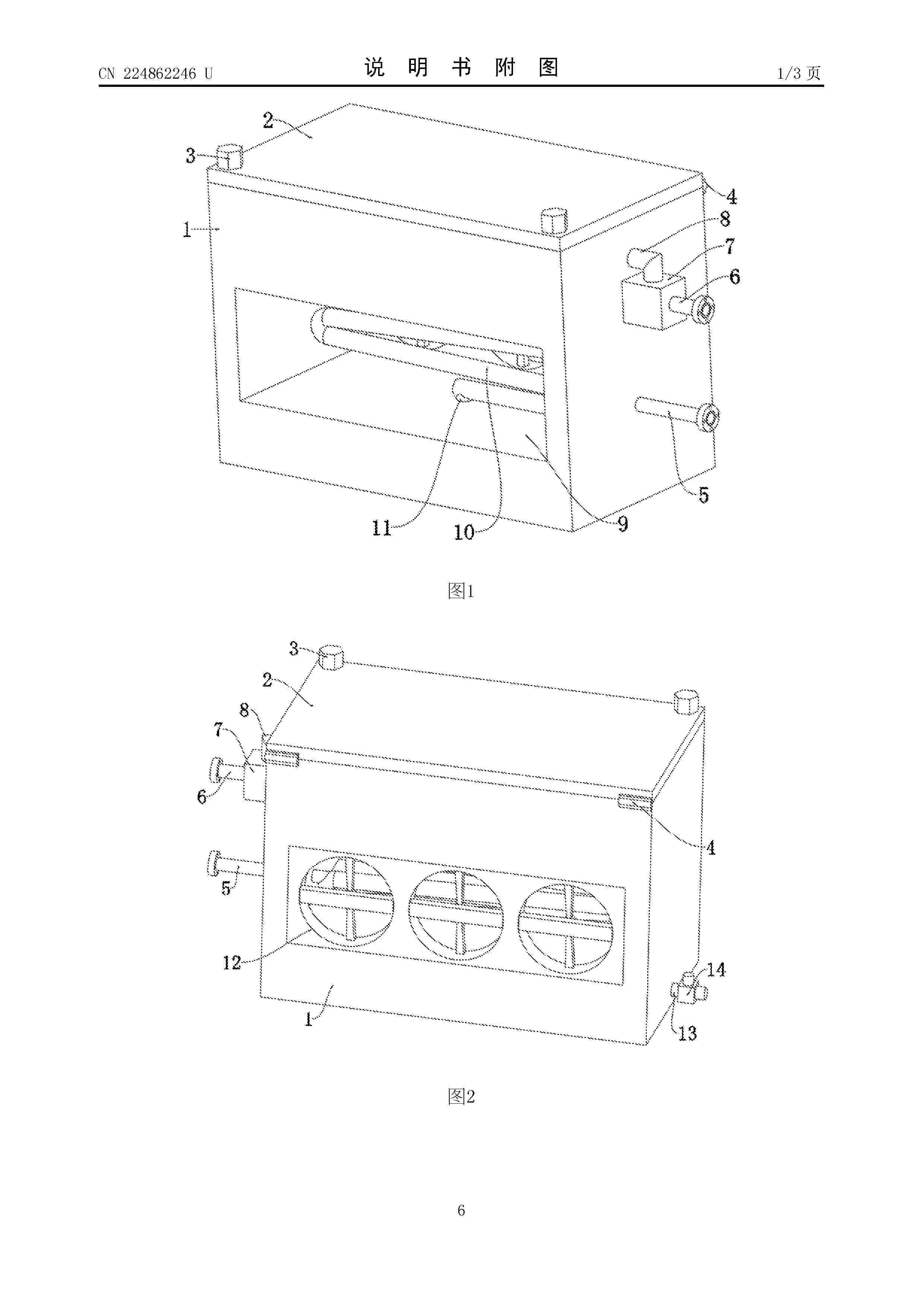
Resumen de: CN224862246U
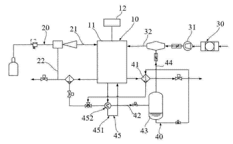
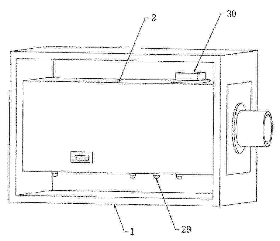
本实用新型公开了一种燃料电池电堆氢气循环装置,涉及燃料电池技术领域,包括干燥箱,所述干燥箱的上端设有干燥腔,所述干燥腔的内部设有干燥机构,所述干燥箱的上端连接有封闭机构,所述干燥箱的侧壁上贯穿设有装置槽,所述干燥腔的左右两侧内壁上分别贯穿设有第二通气管、第一通气管,所述第二通气管远离干燥腔的一端延伸至装置槽的内部,所述第一通气管远离干燥腔的一端延伸至干燥箱的外部,所述干燥箱的外壁上安装有气体循环泵,所述气体循环泵的输入端与第一通气管连接。本实用新型能够实现水汽的高效分离,同时有效保证对氢气的充分干燥,结构简单紧凑,能有效回收排放的氢气进行循环使用。

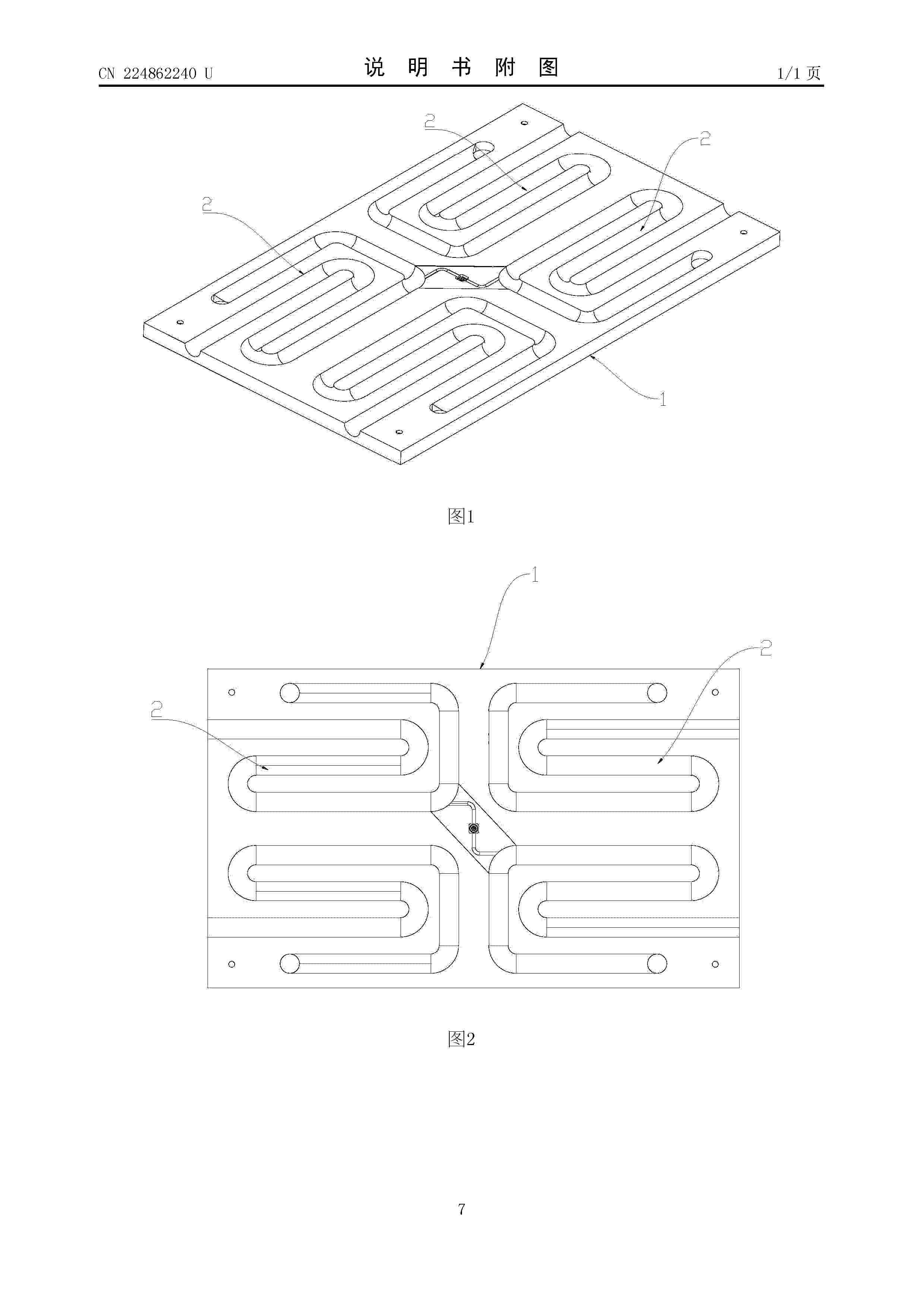
Resumen de: CN224862240U
本实用新型公开了一种全钒液流电池电堆进出液板结构,包括板体,板体内部设有沿板体延伸的内置蛇形流道,板体的侧边开设有进液口和出液口,进液口、出液口分别与所述蛇形流道的两端连通,板体朝向全钒液流电池电堆单电池的一侧设有与单电池电解液进口对应且可密封连通的流道接口,以通过内置蛇形流道替代电堆外部设置的盘管结构。本进出液板将蛇形流道内置,缩短电解液在电堆间的无效传输路径,减少离子定向迁移的驱动力,从结构上抑制旁路电流产生;并且通过板体内置蛇形流道取消外部盘管,省去大量外部管路及管接头,简化系统管路布局,降低原材料采购与装配成本,同时减少密封节点数量,大幅提升密封可靠性,从根源上降低电解液泄漏风险。
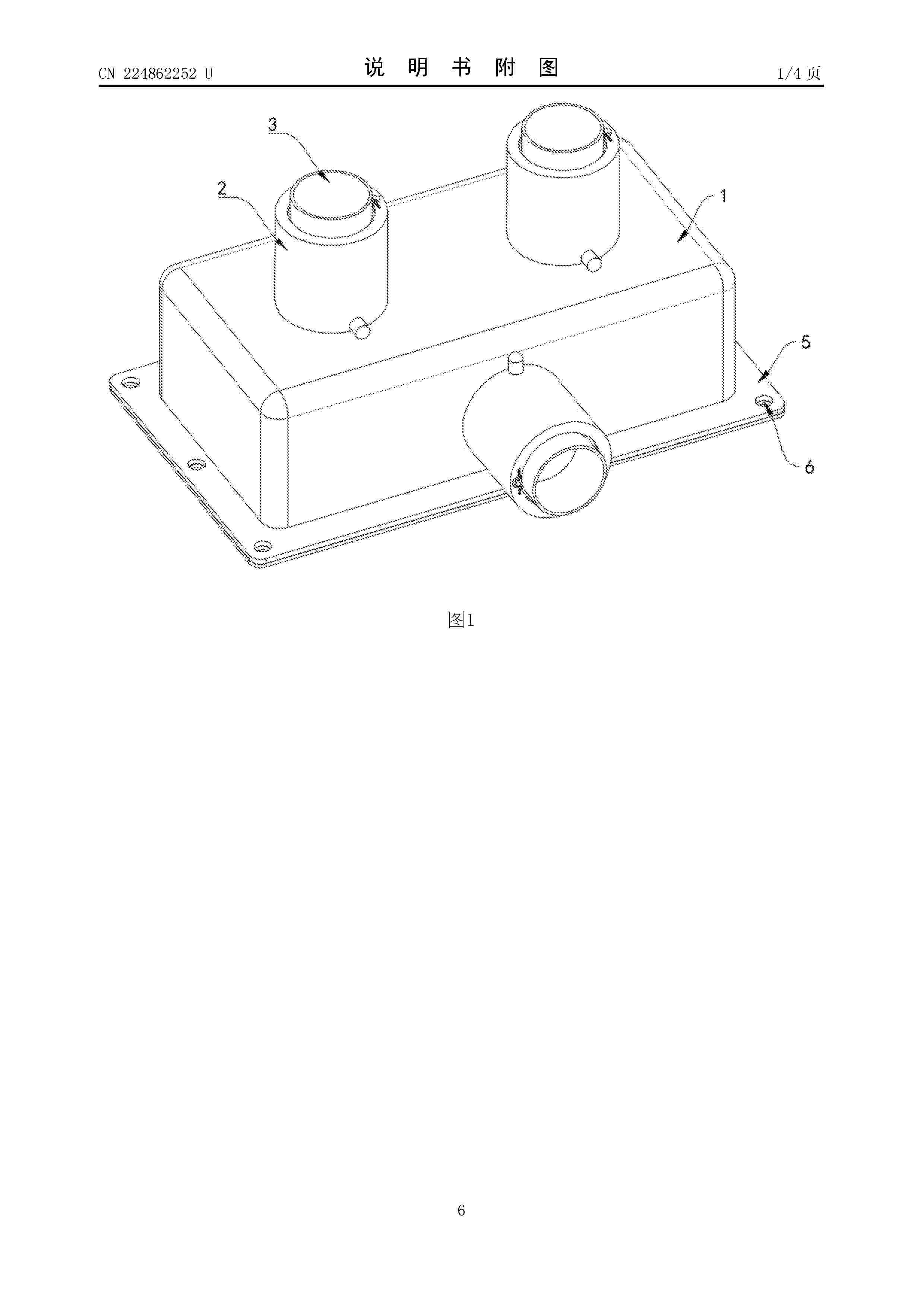
Resumen de: CN224862252U
本实用新型公开了燃料电池用测试歧管,涉及燃料电池技术领域,包括歧管主体,所述歧管主体上方设置有若干个密封组件;所述密封组件包括密封套管,所述密封套管上端内侧开设有第一密封孔,所述密封套管下端内侧开设有第二密封孔,所述第一密封孔和第二密封孔内侧滑动设置有连接气管,所述连接气管上下两端阵列设置有若干个外密封圈且与第一密封孔和第二密封孔内侧贴合。本实用新型通过双密封孔与外密封圈的配合设计,显著提升密封性能;卡扣组件实现气管快速拆装,效率较传统螺纹连接有效提升。
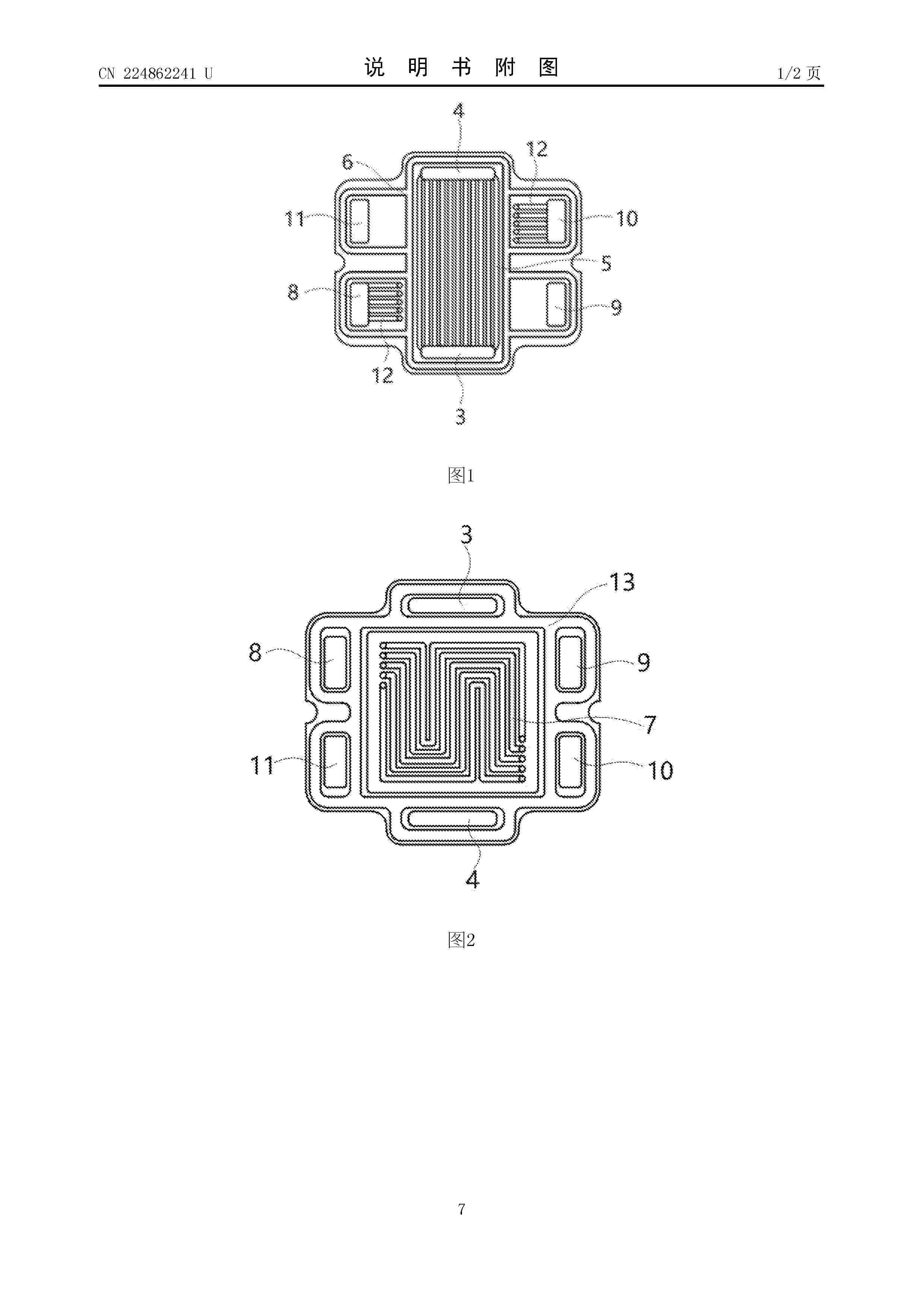
Resumen de: CN224862241U
本实用新型涉及双极板结构领域,尤其涉及一种小功率高温堆燃料电池双极板,包括阳极板和阴极板,所述阳极板和阴极板粘接形成双极板本体,所述双极板本体在相对两侧开设冷却气体进口和冷却气体出口,所述阳极板和阴极板在粘接面设置有冷却气体流道,所述冷却气体流道分别与所述冷却气体进口、冷却气体出口连通形成冷却气路。该冷却气体流道的设计使得冷却气体能够在阳极板和阴极板之间均匀流动,有效地带走燃料电池在工作过程中产生的热量,提高了燃料电池的散热性能。此外,冷却气体进口和冷却气体出口的设置,便于冷却气体的引入和排出,保证了冷却气体在双极板内部的循环流动,进一步增强了散热效果。
Resumen de: CN122930949A
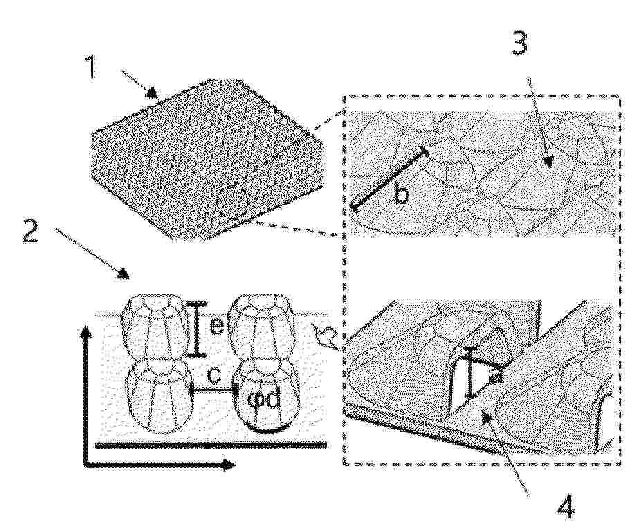
本发明涉及一种静态排水的燃料电池极板流场,该流场(1)由多个仿生微结构(2)排列形成岛阵列;每个仿生微结构(2)包括顶部平面、坡面及底面,所述顶部平面的一侧设有垂直于所述底面的开口平面,所述坡面连接顶部平面的其余各侧与底面;所述坡面具有梯度亲水性,利用非平衡表面张力驱使液态水沿所述坡面定向移动至所述开口平面,形成液态水传输通路(5);相邻仿生微结构(2)之间的极板平面区域具有疏水性,形成气体传输通路(6)。与现有技术相比,本发明可防止液态水积聚,实现快速排水到多孔层,同时避免与气体路径发生干涉,提高了静态排水效率,适用于静态排水方式燃料电池长时间运行。
Resumen de: CN122917262A
本发明提供一种含羧基的聚亚芳基聚合物及其制备方法、离子溶剂化膜及其制备方法和应用。其中,所述聚合物为包含下式I重复结构单元的聚合物:式I;其中,Ar为含有芳环结构的基团;R1为不具有羧基取代的2‑羰基吲哚环基;R2为具有羧基取代的2‑羰基吲哚环基;x为功能化度,0
Resumen de: CN122930967A
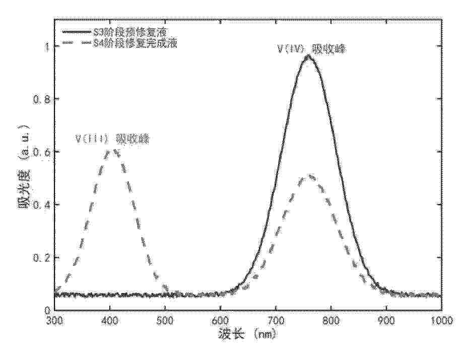
本申请公开了一种全钒液流电池电解液修复耦合生物质高值转化的方法。该方法将价态不匹配的正负极电解液混合,测定钒离子浓度比后,加入氧化剂将V(III)全部氧化为V(IV)获得预修复液;构建由单原子催化剂修饰的石墨毡阴极、负载型泡沫镍阳极和复合双极膜组成的双室电解体系;将预修复液加入阴极室,含生物质的碱性水溶液加入阳极室进行恒流电解,当阴极液平均氧化态降至实用的3.5价等目标价态时停止。本发明利用化学氧化结合电解还原机制精确复原价态且不引入杂质;利用阳极生物质电氧化替代水分解析氧反应,在降低系统修复能耗的同步合成高附加值转化液,实现电池维护与生物质转化的结合。
Resumen de: CN122930963A
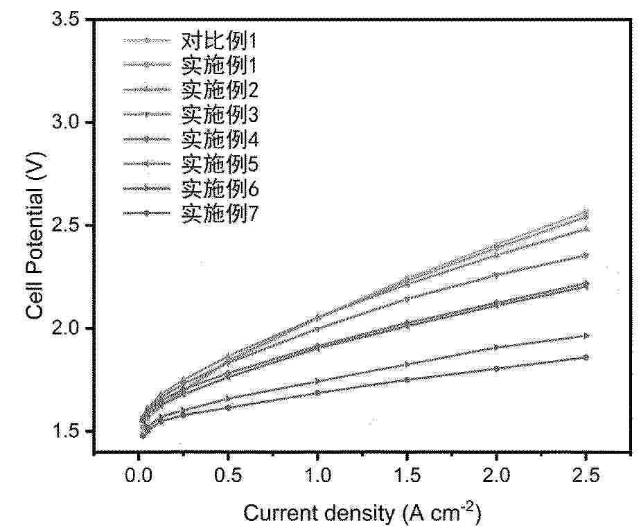
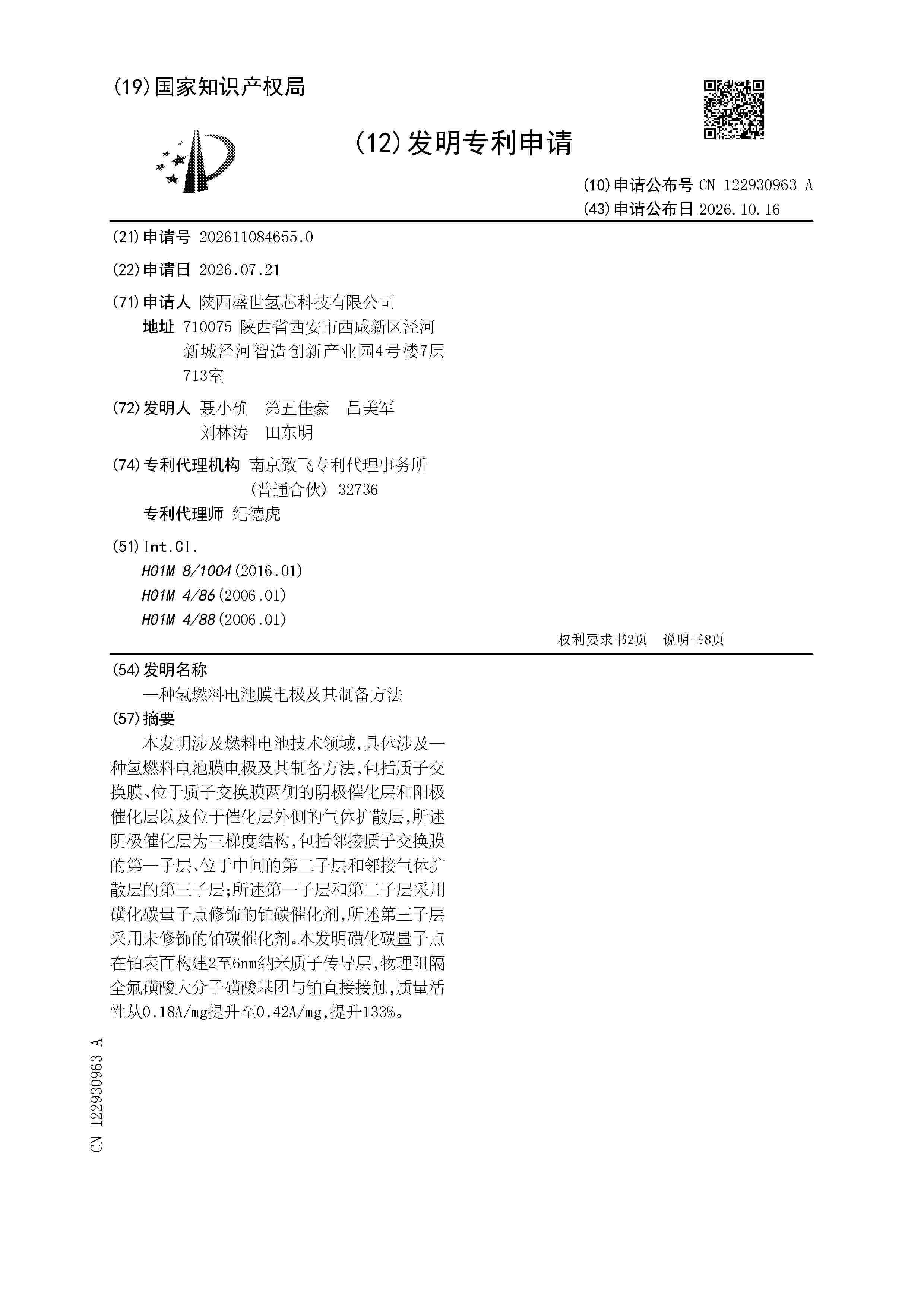
本发明涉及燃料电池技术领域,具体涉及一种氢燃料电池膜电极及其制备方法,包括质子交换膜、位于质子交换膜两侧的阴极催化层和阳极催化层以及位于催化层外侧的气体扩散层,所述阴极催化层为三梯度结构,包括邻接质子交换膜的第一子层、位于中间的第二子层和邻接气体扩散层的第三子层;所述第一子层和第二子层采用磺化碳量子点修饰的铂碳催化剂,所述第三子层采用未修饰的铂碳催化剂。本发明磺化碳量子点在铂表面构建2至6nm纳米质子传导层,物理阻隔全氟磺酸大分子磺酸基团与铂直接接触,质量活性从0.18A/mg提升至0.42A/mg,提升133%。
Resumen de: CN224861737U
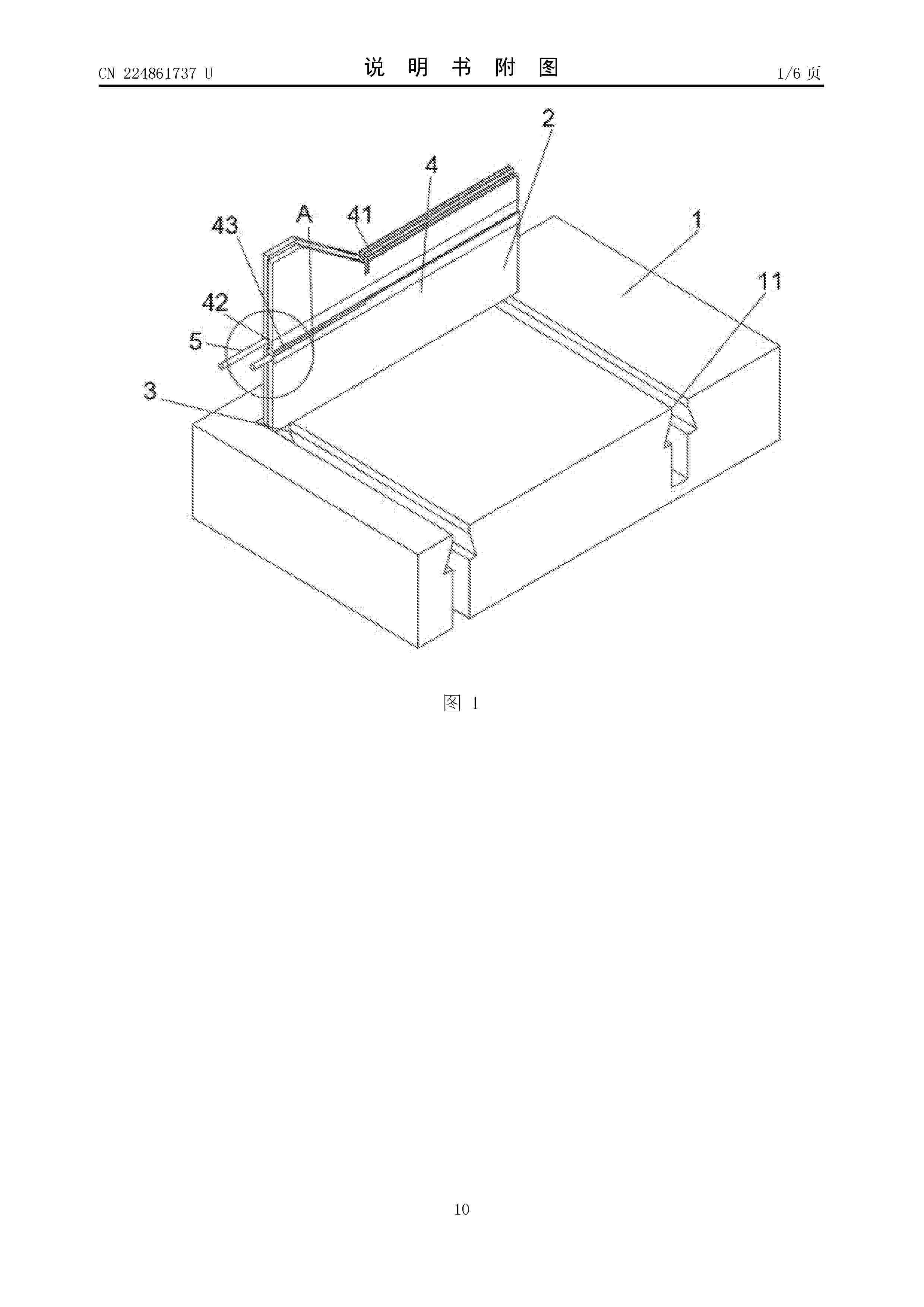
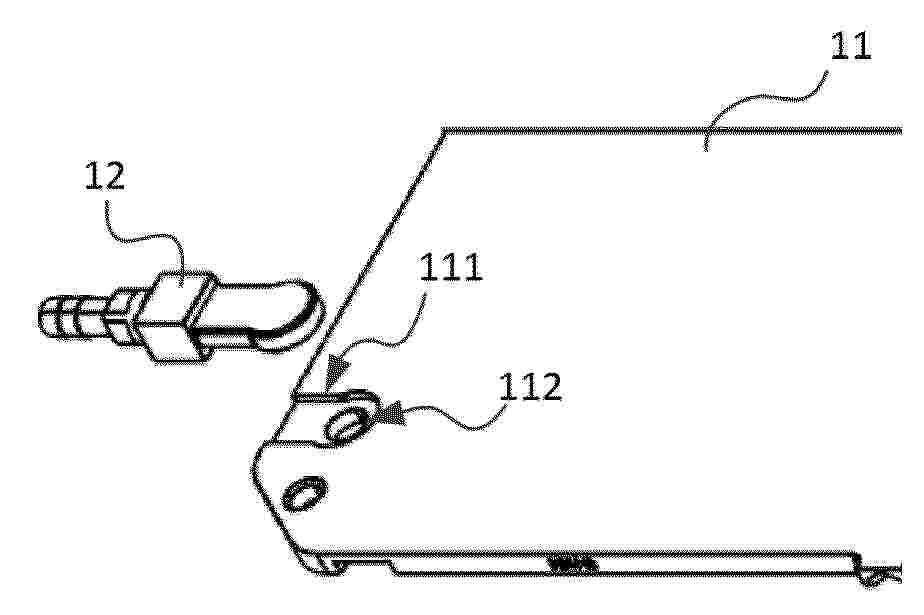
本实用新型公开了一种针对于氢氧燃料电池的可拆卸式CVM模块,包括固定主体和至少一个可拆卸设于所述固定主体上的巡检组件,所述巡检组件包括巡检测试座、信号连接件和滑动连接件;在所述固定主体上开设有滑动轨道,所述滑动轨道的端部设有开口,所述滑动连接件通过所述开口进入所述滑动轨道中并与所述滑动轨道滑动连接;该针对于氢氧燃料电池的可拆卸式CVM模块,本申请通过设置一个固定主体,而在固定主体上配合设置有可拆卸的巡检测试座,金属插片插入在巡检测试座中,巡检测试座通过滑动连接件安装在固定主体上后可以灵活的调节使用位置,区别于现有技术中的大多数的金属插片安装后即不可调节的设置,本申请可移动的巡检测试座更为灵活。
Resumen de: CN122930972A
本申请涉及液流电池领域,提供一种液流电池的电池堆、液流电池系统,电池堆包括多个沿厚度方向堆叠的电池单元,电池单元包括:第一双极板,第一双极板第一表面上设置有第一凹陷部,第二表面上设置有第二流道,第一表面的第一凹陷部通过液流通孔贯通至第二表面的第二流道;液路连接器,液路连接器包括第一连接件、第二连接件,第一连接件的对接部嵌设于第一凹陷部,第一凹陷部与对接部具有对应的形状,第一连接件内设置有第一液流通道,且第一液流通道在对接部形成有用于与液流通孔对应的对接孔;第二连接件用于与外部电解液管道连接,第二连接件内设置有第二液流通道,第二液流通道与第一液流通道连接。
Resumen de: JP2026168947A
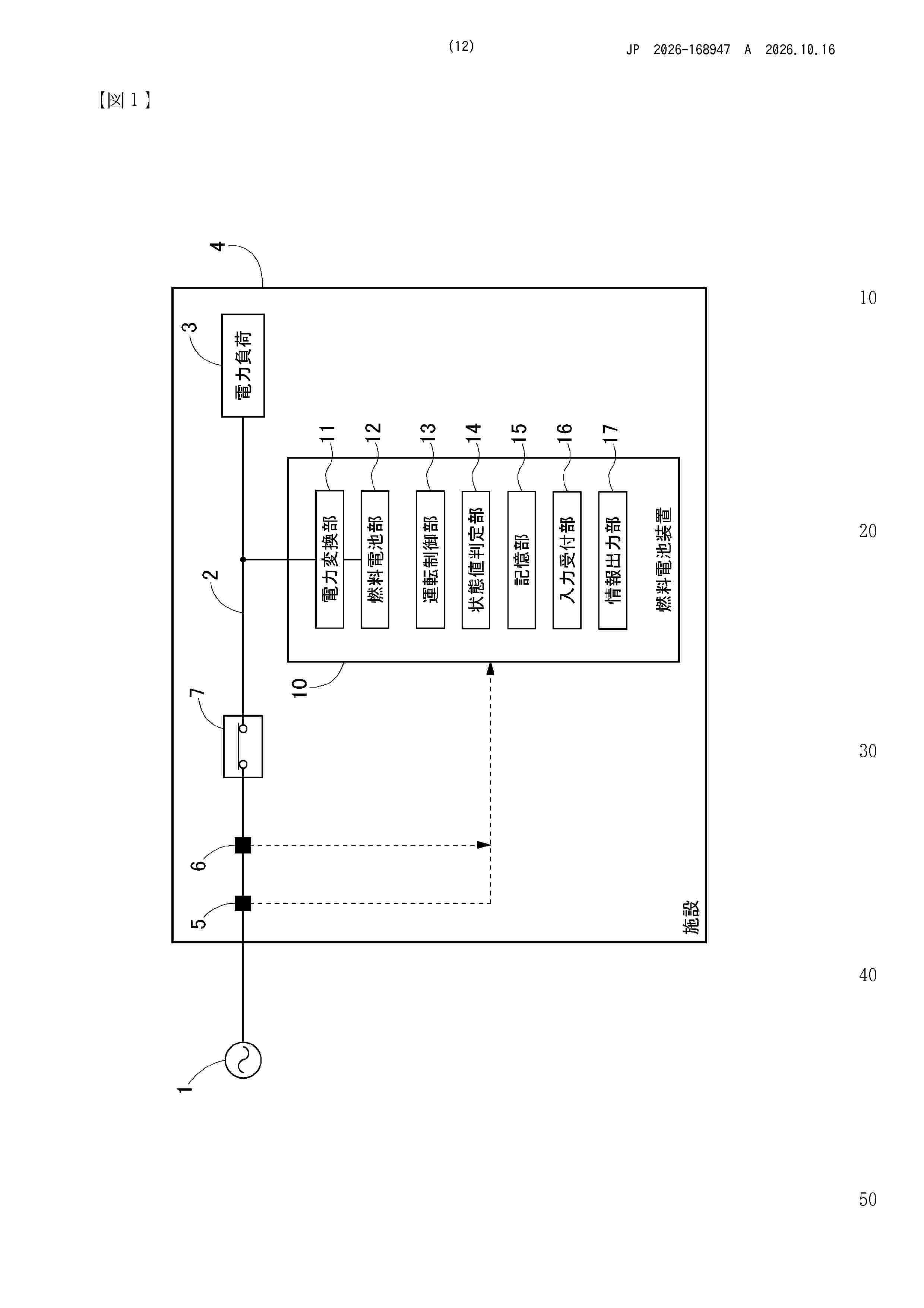
0001 【課題】可能な限り大きな電力を供給できる燃料電池装置を提供する。 【解決手段】電力系統1に連系される燃料電池部12を備える燃料電池装置10であって、電力系統1からの電力供給が正常に行われている正常状態の場合、燃料電池部12の運転状態を示す状態値が所定の第1限度範囲から逸脱することを許容しない状態で出力電力を調節する第1運転を行い、電力系統1からの電力供給が正常に行われていない異常状態であることを含む所定の運転環境条件が満たされる場合、燃料電池部12の運転状態を示す状態値が、第1限度範囲から逸脱することを許容した状態で出力電力を調節する第2運転を行う。 【選択図】図1
Resumen de: CN122930959A
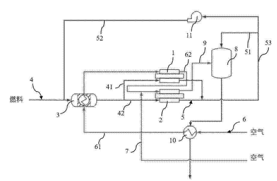
本申请提出了一种固体氧化物燃料电池发电系统及其温度控制方法,固体氧化物燃料电池发电系统包括第一电堆和第二电堆、重整预热机构、燃料供给流路、燃料回收流路、空气供给流路和旁路空气流路。燃料供给流路与重整预热机构连通并用于向重整预热机构输送新鲜燃料,燃料供给流路包括并联设置的第一流路和第二流路,重整预热机构和第一电堆的阳极入口通过第一流路连通,重整预热机构和第二电堆的阳极入口通过第二流路连通。燃料回收流路与燃料供给流路连通,燃料回收流路被配置为回收从第一电堆的阳极和第二电堆的阳极排出的阳极尾气,并将部分的阳极尾气通过燃料供给流路输送给重整预热机构。本申请能够提升系统整体的发电效率。
Resumen de: CN122930937A
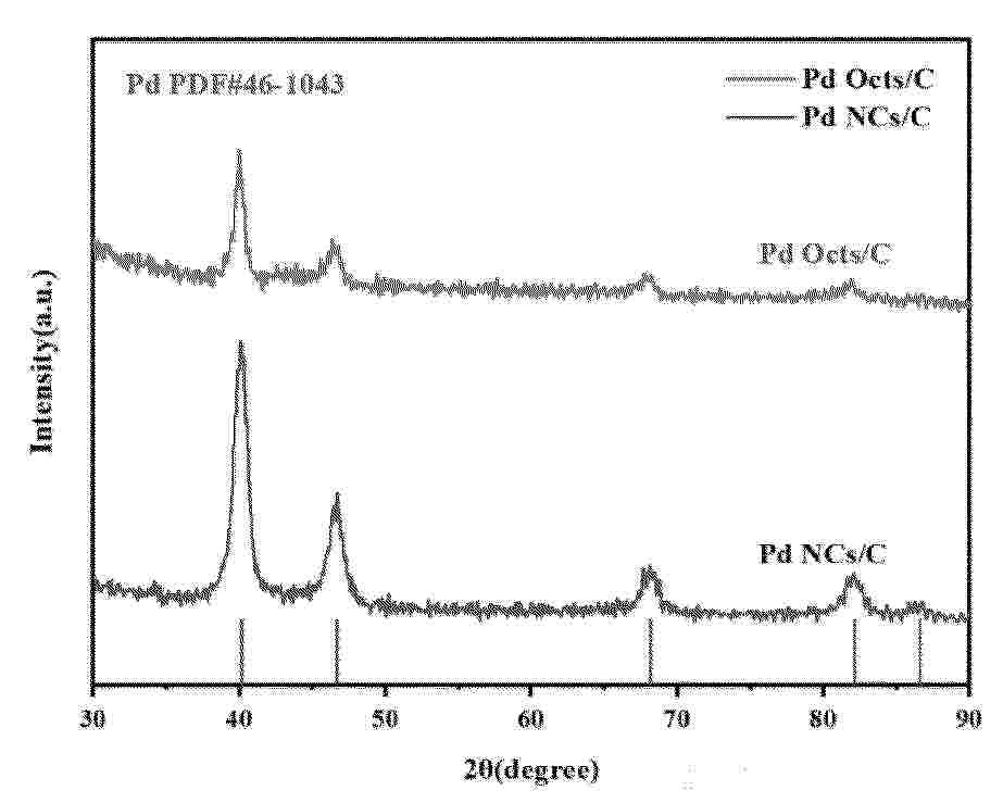
本发明公开一种八面体PdHx@Pt核壳催化剂及其制备方法和应用,制备方法为:A、将制备的Pd纳米立方体分散于乙二醇中得Pd纳米立方体分散液;B、将Pd纳米立方体分散液、聚二烯二甲基氯化铵溶液、乙酸和亚硝酸钠水溶液加入乙二醇中,反应后离心收集产物,得到表面暴露{111}晶面为主的Pd纳米八面体,将其分散于乙二醇中得Pd纳米八面体分散液;C、将Pd纳米八面体分散液、抗坏血酸、溴化钾、聚乙烯吡咯烷酮与乙二醇混合,在加热条件下滴入H2PtCl6·6H2O溶液,反应后离心收集固体得八面体PdHx@Pt核壳催化剂,其中x的取值范围为:0.064~0.413。本发明实现对催化剂电子结构和晶格应变的协同调控。
Resumen de: CN122931088A
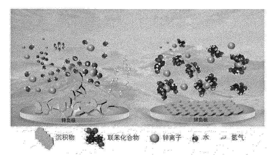
本发明涉及一种联苯结构水系电解液、储能器件及其制备方法,属于储能技术领域;本发明通过在水系电解液中引入苯环上连有极性官能团的联苯类衍生物进行化学改性,该类化合物可在锌负极表面吸附形成界面保护层,有效抑制锌枝晶生长与电解液副反应;同时可调控锌离子溶剂化结构,降低体系自由水活性;此外,联苯类衍生物可作为氧化还原活性分子,提供额外法拉第容量;本发明通过优化电解液组分与溶剂化结构,改善了电极/电解液界面性能,能够拓宽器件工作电压窗口、提升比容量,显著抑制锌负极析氢、腐蚀等失效问题,有效提升锌离子混合电容器及锌离子电池的长循环稳定性与综合电化学性能。
Resumen de: CN122916439A
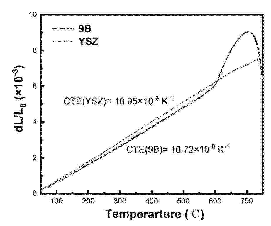
一种中低温固体氧化物燃料电池封接用锶锌硼硅系玻璃材料及其制备和使用方法,涉及一种中低温固体氧化物燃料电池封接用的玻璃材料及其制备方法。本发明采用SrO‑ZnO‑B2O3‑SiO2四元玻璃体系,通过无BaO和较低B2O3含量的组成设计,并调控各组分比例,使玻璃材料析晶起始温度高于600℃~700℃中低温固体氧化物燃料电池的工作温度,并且在封接过程中能够实现烧结致密化和有限软化,随后析晶形成含SrSiO3、Sr2ZnSi2O7和SrB4O7晶相的微晶玻璃封接层,同时获得与铁素体不锈钢连接体和氧化物陶瓷电解质相匹配的热膨胀性能,从而满足600℃~700℃中低温固体氧化物燃料电池部件之间的封接要求。
Resumen de: CN122930931A
本发明提供一种液流电池负极材料及其制备方法和应用,该方法包括:(1)在溶剂存在下,将催化剂、分散剂和亲水树脂接触分散,得到浸渍液;(2)将碳材料置于浸渍液中进行至少2次浸渍处理,得到液流电池负极材料;在步骤(2)中,每次进行浸渍处理采用的浸渍液固含量不同,且后一次浸渍处理采用的浸渍液固含量比前一次浸渍处理采用的浸渍液固含量低。本发明提供的方法,将碳材料在含催化剂和亲水树脂的浸渍液中进行2次以上的连续梯度浸渍处理,能够提高电极材料亲水性,以及提供均匀有效的催化剂活性位点,有效控制催化剂负载量,从而提高催化剂利用效率。
Resumen de: CN122930976A
本发明涉及液流电池技术领域,公开了一种气液两相液流电池系统,所述气液两相液流电池系统包括:气液两相液流电池组、气相供给管路和液相供给管路;气液两相液流电池组包括一节气液两相单电池或至少两节串联连接的所述气液两相单电池;气相供给管路安装有气体输送装置且与所述气液两相液流电池组的气相进口相连通;液相供给管路的两端各自与所述气液两相液流电池组的液相进口和液相出口相连通形成循环管路,所述液相供给管路上连通有液相储罐且安装有循环泵。本发明具有低成本、高安全性、高灵活性的优势。
Resumen de: CN224860412U
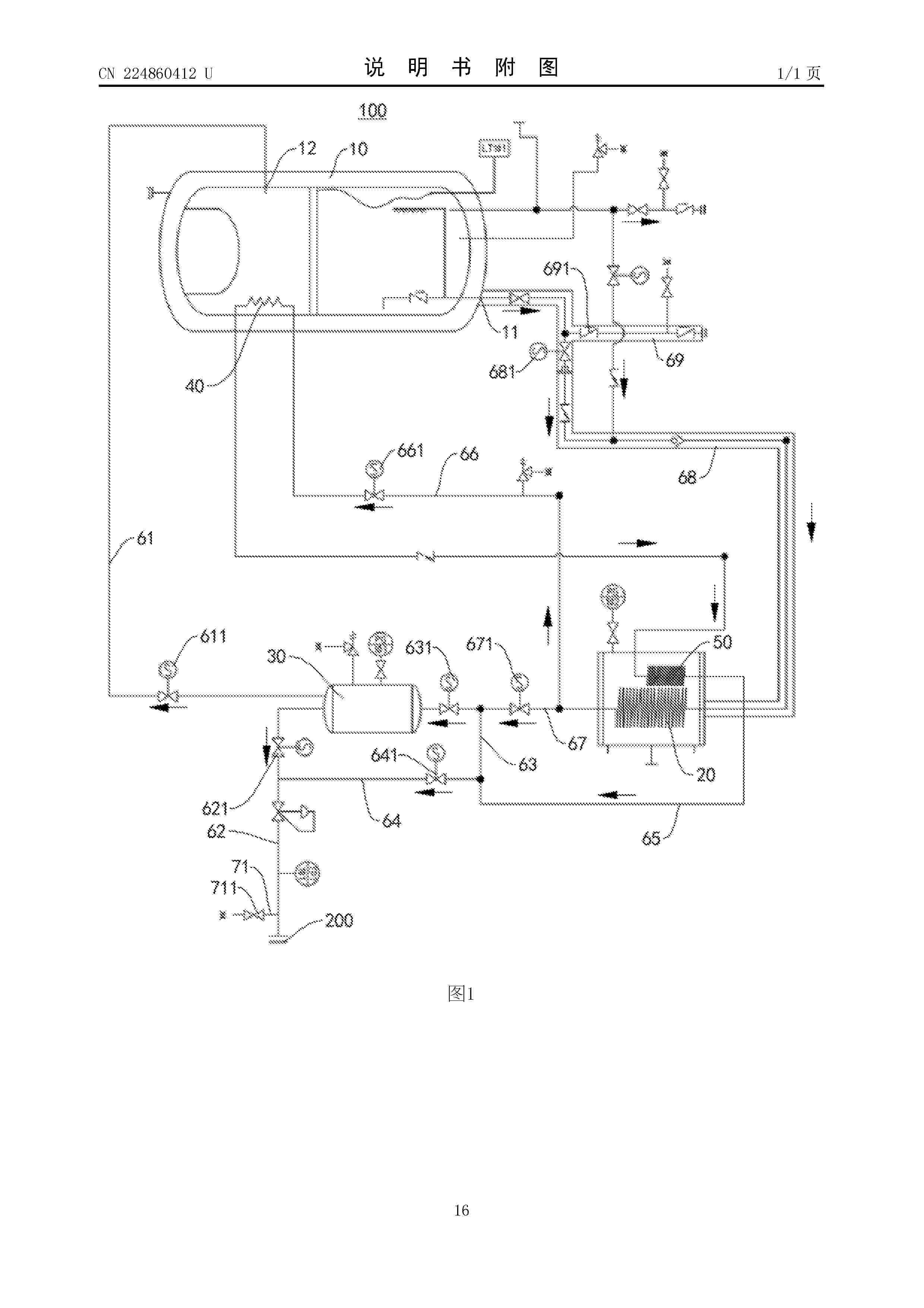
本实用新型公开了一种液氢系统和车辆,液氢系统包括:储氢瓶,储氢瓶具有第一开口和第二开口;汽化器,汽化器的进口端与第一开口连通;缓冲罐,缓冲罐的进口端与汽化器的出口端连通,缓冲罐的出口端择一地与第二开口和燃料电池电堆连通;增压件和加热件,增压件位于储氢瓶内且两端分别与汽化器的出口端和加热件的进口端连通,加热件的出口端与燃料电池电堆连通。根据本实用新型实施例的液氢系统,能够在液氢系统加注完成后即刻满足储氢瓶出液供氢的要求,以加快燃料电池电堆的启动速度,用户使用体验较好。
Resumen de: CN224857805U
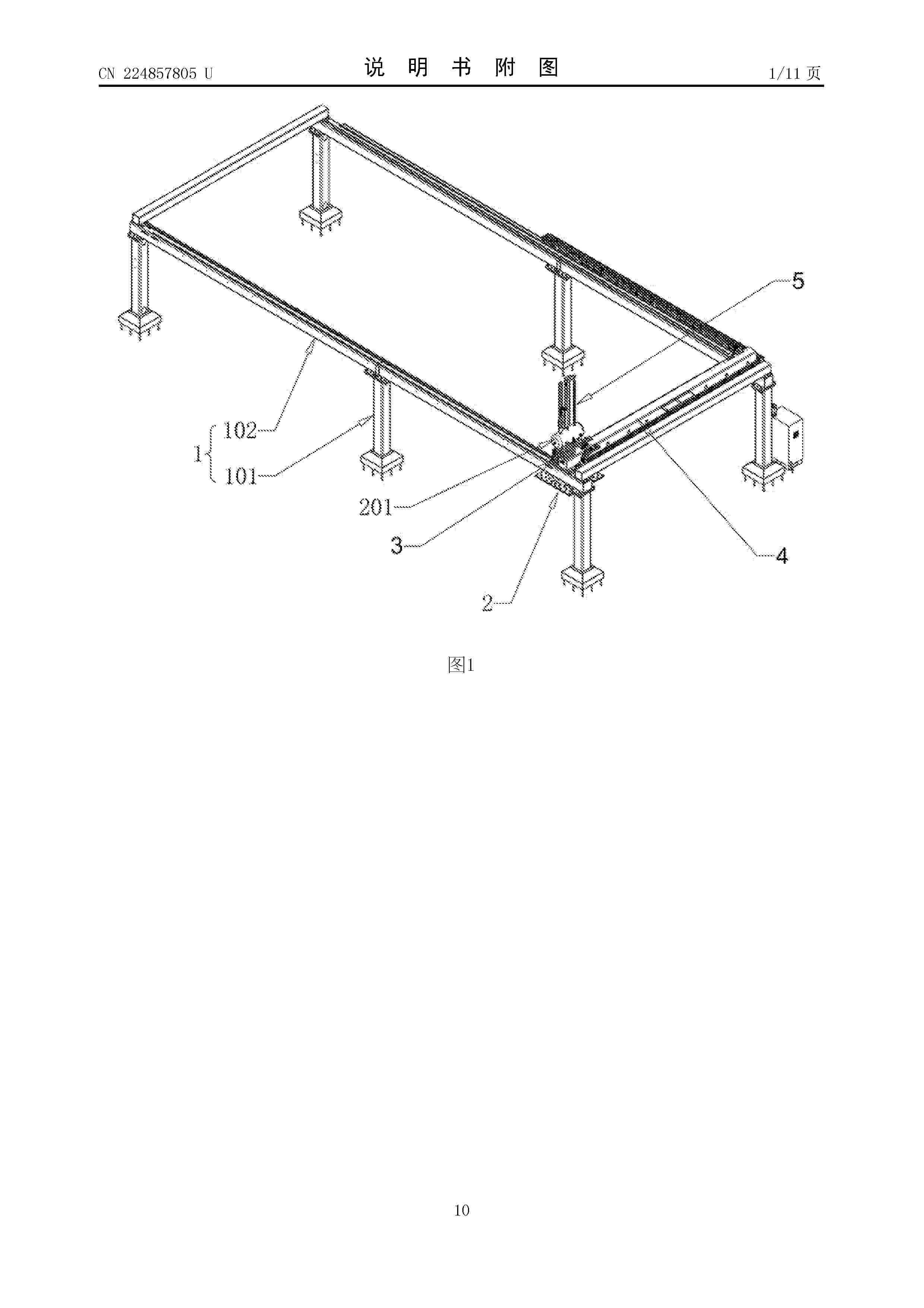
本实用新型涉及电化学电池生产设备技术领域,具体涉及一种用于膜电极制备的转运装置。该装置包括架体和抓取机构,抓取机构活动连接在架体上;抓取机构包括负压单元和板体,板体的下侧设有吸附区和避让区;板体位于吸附区的区域开设有多个安装孔,安装孔内设置有吸盘,板体下侧位于避让区的区域设置有避让槽。通将避让区对准基底膜上的催化剂涂覆区域,通过吸盘吸住基底膜,从而抓取基底膜,不容易损坏基底膜。由于吸盘设置在吸附区内,吸盘不会吸住基底膜上的催化剂,能够避免吸盘对催化剂层造成损坏;并且由于避让区内设有避让槽,能够避免板体与基底膜上的催化剂接触,从而保证催化剂层的完整性。
Resumen de: CN224862248U
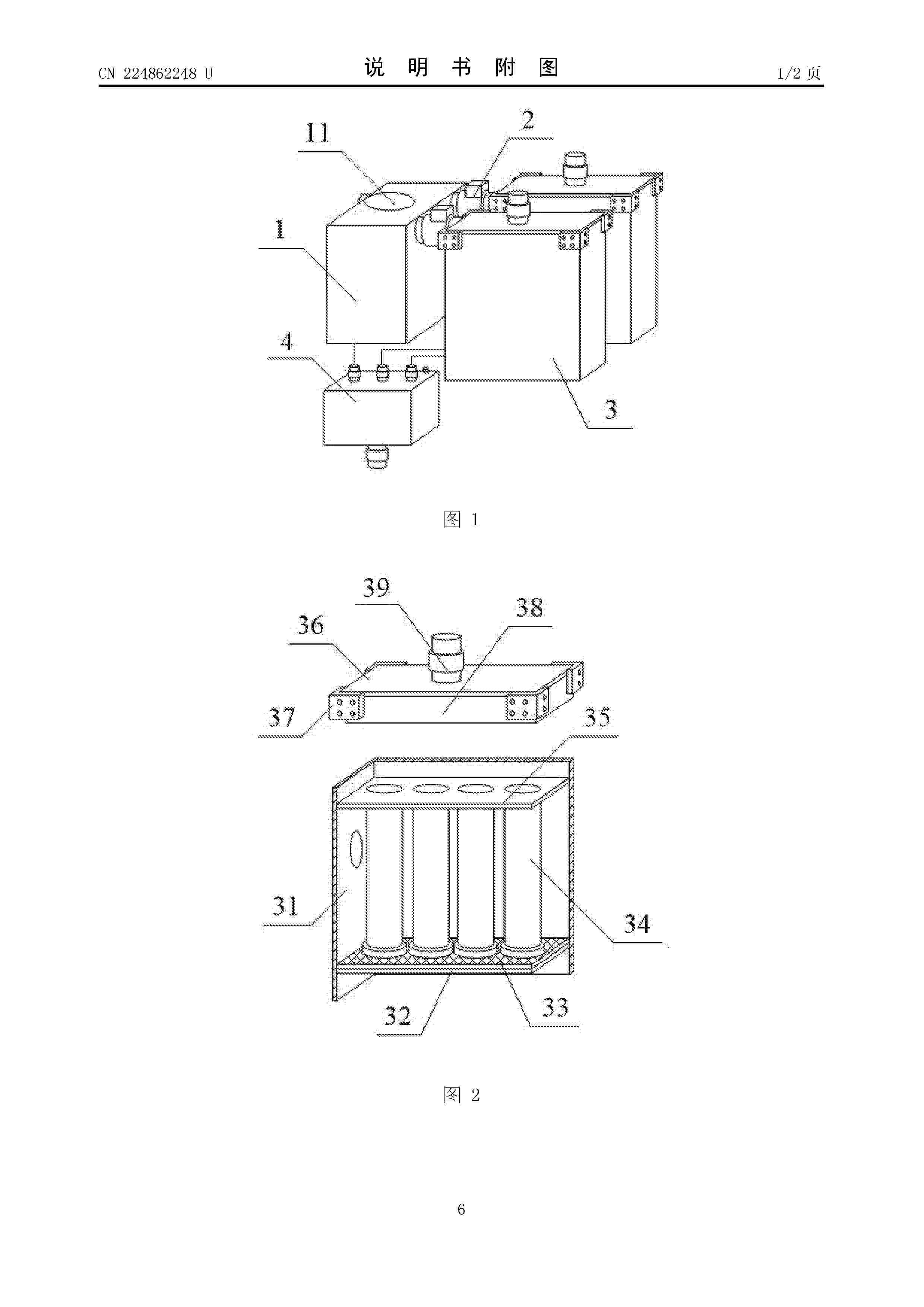
本实用新型提供一种新型的氢燃料电池气水分离装置,包括第一分离箱、第二分离箱组件和集水箱组件,第一分离箱的内部固定安装有旋风分离器,旋风分离器的进气端延伸至第一分离箱的外部,旋风分离器的出气端和出水端均设置在第一分离箱的内部,第一分离箱的一侧上部并排开设的出气口处均安装有气阀,两个所述气阀分别与两个所述第二分离箱组件连接。本实用新型箱体,支撑框架,底板,气水过滤筒,顶架,箱盖,安装座,回形框架,排气阀的设置,有利于实现气水的连续分离。
Resumen de: CN122930971A
本申请涉及航空燃料电池技术领域,具体而言,涉及一种航空跨温区质子交换膜燃料电池系统及控制方法。航空跨温区质子交换膜燃料电池系统包括燃料电池组件、氢气输送组件、空气输送组件和空气加湿组件。燃料电池组件包括跨温区电堆,跨温区电堆的运行温区大于105℃。空气加湿组件包括气水分离单元、回流管路单元、泄压闪蒸单元和增湿管路单元。跨温区电堆的阴极出口、气水分离单元、回流管路单元、泄压闪蒸单元、增湿管路单元和输气单元依次连通。本申请能够解决航空跨温区燃料电池电堆的运行温度较高,增湿需求大,常规的增湿方案难以维持稳定气态加湿环境的问题。
Resumen de: CN122912645A
本发明涉及应用于分离领域的一种氢燃料电池温湿度自适应空气过滤装置,通过除湿机构对抽入到过滤装置内的气流进行加热和除湿作业,使得气流的温度和湿度符合设定要求,进而减少低温高湿气流对过滤芯的负面影响,提高过滤芯的过滤质量和使用寿命;同时,通过第一制冷片、第二制冷片和电控换向阀三者的配合,实现加热作业和除湿作业的快捷切换,满足不同的使用需求,并提高冷凝除湿的效率;另外,通过先加热后冷却的冷凝方式提高冷凝效率,同时空气中的粉尘加速冷凝水滴成型,而水滴对粉尘具有较好的吸附效果;此外,通过设有导向板和导向块,使得气流与制冷片充分接触,并加速水滴滴落和粉尘清理。
Resumen de: CN122918746A
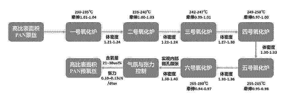
本发明公开了一种液流薄电极的高比表面积PAN基预氧丝梯度预氧化制备方法,涉及聚丙烯腈基预氧丝制备技术领域,采用六台独立控温氧化炉串联、缓梯度升温、纤维运行速度12–20m/min、总预氧化时间30–60min、富氧气氛、循环风均衡供氧、新风与废气平衡排放的工业化工艺,创新采用前期微正牵、后期梯度强负牵、总牵伸倍率0.92–0.98、极低张力0.10–0.13cN/dtex,全程以保孔、扩孔、提升比表面积、提高柔顺性、平缓提升体密度为核心,与传统碳纤维路线完全相反。本发明工艺稳定、适配现有产线,制备的预氧丝具有高比表面积、体密度合理、高柔顺、低收缩、无皮芯、孔道贯通等特点,完美解决超薄针刺断纤、破网、面密度不均、起皱翘边等问题。
Resumen de: CN122918134A
本发明提出了一种高导电性胞外聚合物及其制备方法与应用,属于生物材料技术和环境生物技术交叉领域。以解决现有导电生物材料制备依赖化学合成、生物相容性差、工艺复杂,以及天然胞外聚合物导电性不足、缺乏三维连续导电网络结构的技术问题。它包括培养基中接种微藻和含酰化高丝氨酸内酯响应性革兰氏阴性菌的活性污泥,添加N‑十二酰基高丝氨酸内酯进行诱导培养,提取得到胞外聚合物。
Nº publicación: CN122930938A 16/10/2026
Solicitante:
中国科学技术大学榆林大学
Resumen de: CN122930938A
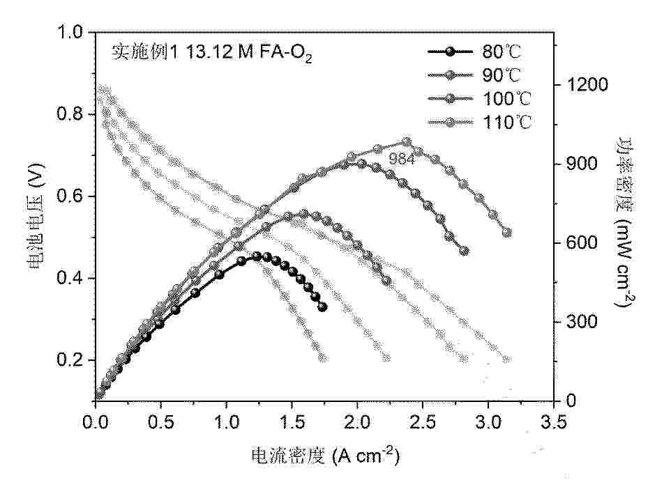
本发明公开一种高甲酸电氧化性能的钯基甲酸燃料电池阳极催化剂及其制备方法与应用,该催化剂的制备包括:将硝酸锌、2‑甲基咪唑与Rh前驱体溶解混合后经水热、干燥、还原气氛焙烧制得Rh单原子负载的氮掺杂碳材料(Rh/NC);将其分散于乙二醇后,加入PdCl2盐酸溶液,调pH后经微波还原、抽滤、干燥、研磨即得催化剂。本发明所得催化剂中Rh呈单原子分散,最高载量5wt%,Pd颗粒分布均匀。该催化剂用于甲酸电氧化反应,具有高电流密度和高功率密度,且稳定性优异。本发明制备工艺简便、环境友好,适于大规模生产。
 BOPI
BOPI
 Sede Electrónica