Si deseas distinguir tus productos, servicios o ambos de los de otra empresa, es posible que necesites una marca o nombre comercial. Descubre qué son, en qué consiste su procedimiento de registro y qué implica.

Información sobre los plazos de presentación de solicitudes de transformación de marcas de la Unión Europea en marca nacional española. Más información


Si tienes un nuevo dispositivo, producto o procedimiento que resuelva un problema técnico o tenga una ventaja práctica, existen distintas formas de protegerlo en España y en otros países. Descubre cómo hacerlo.

¿Tu innovación reside en la estética, la ornamentación o la apariencia de tu producto? Protégela mediante un diseño industrial. Descubre qué derechos confiere el registro y cómo realizar la tramitación.

Las indicaciones geográficas protegen el nombre de un producto originario de una zona geográfica, a la cual le debe una determinada calidad, reputación u otra característica. Descubre qué son, en qué consiste su procedimiento de registro y qué beneficios conceden.

Las patentes publicadas en todo el mundo son una valiosa fuente de información científica, técnica y comercial.

Si eres emprendedor/a o una empresa y quieres potenciar y mejorar la rentabilidad de tu negocio protegiendo de forma adecuada los activos intangibles de tu organización, en este espacio encontrarás lo necesario.


 1357
resultados
1357
resultados
 Última actualización
05/05/2026 [07:31:00]
Última actualización
05/05/2026 [07:31:00]


 Resultados 275 a 300 de 1357

Resumen de: WO2026087734A1
The invention relates to a cathode active material for sodium-ion batteries, comprising a layered oxide structure with lithium doping to enhance air stability and electrochemical performance. The material has a general formula NabLixXyMnzMrO2, wherein X is one or a combination of Cu and Ti, M is at least one of Fe, Co, or Ni, and the atomic ratios satisfy 0.50 ≤ b ≤ 0.70, 0.05 ≤ x ≤ 0.30, 0 ≤ y ≤ 0.80, 0 < z ≤ 0.90, 0 ≤ r ≤ 0.90, with x + y + z + b + r = 1.0. The cathode active material comprises one or more P2-type phases and exhibits phase retention of at least 50% after prolonged exposure to high humidity. A method for preparing the material is also disclosed, involving sol-gel synthesis, chelation, pre-sintering, and high-temperature calcination. The invention further relates to sodium-ion batteries incorporating the cathode material, which demonstrate improved discharge capacity, energy density, and cycle retention, making them suitable for use in consumer electronics, energy storage systems, and electric vehicles.

Resumen de: DE102024131845A1
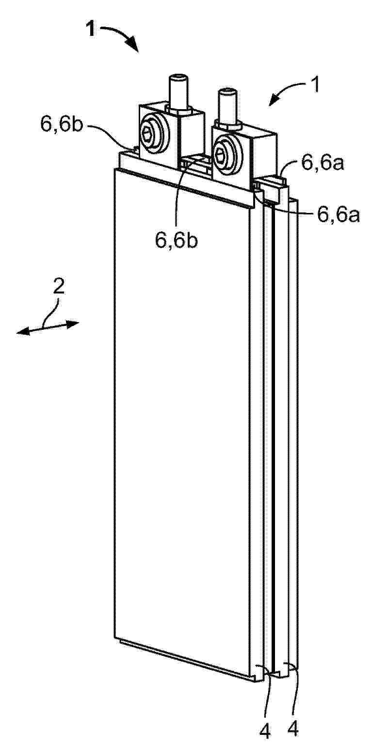
Die Erfindung betrifft einen Zellverbinder (1, 1a, 1b) für Pouch-Zellanordnungen (42) eines Batteriepacks (58), wobei der Zellverbinder ausgestaltet ist, zwei in einer Stapelrichtung (2) übereinanderliegende Pouch-Zellen (4, 4a, 4b) mit jeweils einer ersten und einer zweiten, in Stapelrichtung von einer Öffnung (8) durchsetzten Elektrode (6, 6a, 6b) zu verbinden, und ferner aufweist: einen elektrisch leitfähigen Kontaktkörper (12), der ausgestaltet ist, die ersten Elektroden in Stapelrichtung elektrisch zu verbinden, wobei der Kontaktkörper zwei in Stapelrichtung parallel zueinander angeordnete Elektrodenauflageflächen (16) aufweist, und wobei der Kontaktkörper von einer Durchgangsöffnung (18) durchsetzt ist, die sich in Stapelrichtung zwischen den Elektrodenauflageflächen erstreckt; und eine wenigstens abschnittsweise in der Durchgangsöffnung angeordnete Klemmvorrichtung (14), die ausgestaltet ist, jede der ersten Elektroden gegen wenigstens eine der Elektrodenauflageflächen zu drücken. Ein solcher Zellverbinder erhöht die Stabilität und Lebensdauer von Pouch-Batterien und verringert gleichzeitig den Wartungsaufwand und die Kosten.
Resumen de: US20260121204A1
A cover for an energy storage apparatus includes: a rotation shaft arranged on one side of an open upper surface of an apparatus main body; and a cover main body having one end portion fixed to the rotation shaft and configured to open and close the open upper surface of the apparatus main body by being wound or unwound around the rotation shaft at the one end portion thereof.
Resumen de: WO2026085884A1
A battery cell (10), a battery apparatus (100), an electric device, and an energy storage device. The battery cell (10) comprises a housing (22), an end cover (21), an electrode terminal (211), an electrode assembly (23), and an insulating member (30), wherein the housing (22) is provided with an accommodating cavity (221), the end cover (21) seals the accommodating cavity (221), and the electrode terminal (211) is provided on the end cover (21); the electrode assembly (23) is provided within the housing (22), the electrode assembly (23) comprises an electrode tab (231) and an electrode main body (232), the electrode tab (231) protrudes from the electrode main body (232) toward the end cover (21), and the electrode tab (231) is electrically connected to the electrode terminal (211); the insulating member (30) is provided between the end cover (21) and the electrode assembly (23), the insulating member (30) comprises a body portion (31) and a boss (32), the boss (32) comprises a first surface (33) facing the electrode main body (232), a total area of the first surface (33) is greater than or equal to 1/a times the weight of the electrode main body (232), wherein a is greater than or equal to 0.008 and less than or equal to 0.026, the total area is expressed in square millimeters, the weight is expressed in newtons, and a is expressed in megapascals.
Resumen de: DE102025139624A1
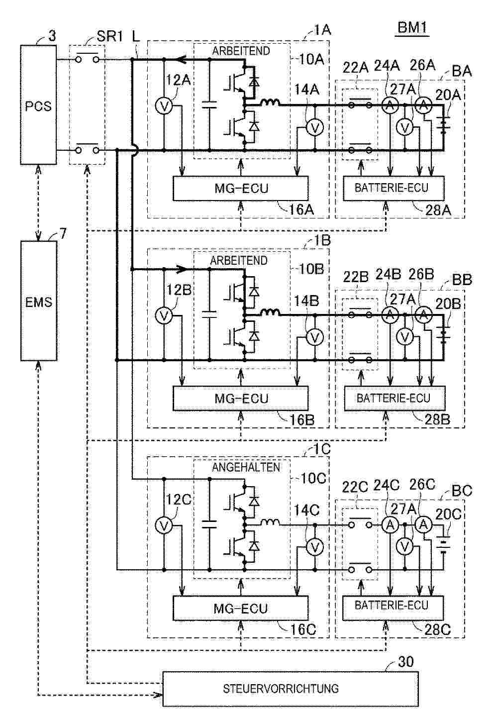
Jedes aus Batteriepacks umfasst einen ersten und einen zweiten Stromdetektor, die einen durch einen Batteriestapel fließenden Strom erfassen. Wenn die erfassten Werte des ersten und des zweiten Stromdetektors in einem Batteriepack nicht übereinstimmen, wird der Austausch von elektrischer Energie zwischen diesem Batteriepack und einem anderen Batteriepack durch eine Steuervorrichtung durchgeführt, die einen zu jedem Batteriepack gehörenden DC/DC-Wandler in Betrieb setzt. Während des Betriebs des DC/DC-Wandlers vergleicht die Steuervorrichtung die erfassten Werte des ersten und zweiten Stromdetektors in dem einen Batteriepack mit dem erfassten Wert des ersten Stromdetektors in dem anderen Batteriepack und wählt einen normalen Stromdetektor aus dem ersten und zweiten Stromdetektor in dem einen Batteriepack aus.
Resumen de: WO2026089104A1
Provided is a positive active material for a lithium secondary battery, comprising a core particle and a coating layer formed on at least a portion of the surface of the core particle, wherein the core particle includes a lithium-containing metal oxide, the coating layer includes cobalt and boron, the amount of boron is 0.02-0.08 wt% on the basis of the positive active material, and the BET value of the positive active material is 0.9 m2/g to 1.05 m2/g.
Resumen de: WO2026089418A1
An anode active material according to an embodiment of the present invention comprises a silicon carbon (Si/C) composite, wherein the silicon carbon (Si/C) composite has a Dmin value of about 0.9 µm or more when pressed at a pressure of about 3-9 tons.
Resumen de: DE102024210436A1
Die vorgestellte Erfindung betrifft einen Abscheider (100, 110) zum Abscheiden eines Fluids aus einem Stoffgemisch,wobei der Abscheider (100, 110) umfasst:- ein erstes elektrisches Kopplungselement (101),- ein zweites elektrisches Kopplungselement (103) und- eine Anzahl Schichtanordnungen (113),wobei eine jeweilige Schichtanordnung (113) umfasst:- eine erste Elektrode (105a),- eine zweite Elektrode (105b),- einen zwischen der ersten Elektrode (105a) und der zweiten Elektrode (105b) angeordneten Separator (109),- ein erstes Leitelement (107a),- ein zweites Leitelement (107b) und- einen elektrischen Isolator (111),wobei die erste Elektrode (105a), der Separator (109) und die zweite Elektrode (105b) zwischen dem ersten Leitelement (107a) und dem zweiten Leitelement (107b) angeordnet sind unddas erste Leitelement (107a) auf dem Isolator (111) aufliegt, undwobei eine jeweilige Schichtanordnung (113) in mehreren Lagen um das erste elektrische Kopplungselement (101) herumgewickelt ist und das zweite elektrische Kopplungselement die Anzahl Schichtanordnungen (113) umgibt.
Resumen de: DE102024210447A1
Die Erfindung betrifft ein Verfahren zum Überwachen einer Isolation zwischen zwei elektrischen Leitungen (102, 103), insbesondere elektrischen Hochvolt-Leitungen, und Masse (104) mittels einer Isolationsüberwachungs-Schaltung, wobei die Isolationsüberwachungs-Schaltung zwei Schalter (SWTestP, SWTestM) aufweist, das Verfahren aufweisend die folgenden Schritte: (a) Ändern eines Schaltzustands (115, 116) der zwei Schalter (SWTestP, SWTestM) zu einem ersten Zeitpunkt (t1); (b) erneutes Ändern des Schaltzustands (115, 116) der zwei Schalter (SWTestP, SWTestM) zu einem zweiten Zeitpunkt (t2), welcher ein vorgegebenes Zeitintervall (114) nach dem ersten Zeitpunkt (t1) liegt; (c) Empfangen eines Messwerts (Pha2, Pha3), der für eine Spannung (UChsGnd) zwischen einer ersten elektrischen Leitung (103) der beiden elektrischen Leitungen (102, 103) und Masse (104) zu einem dritten Zeitpunkt (t3) während des vorgegebenen Zeitintervalls (114) repräsentativ ist; (d) Empfangen eines Änderungswerts (ΔUBat), der für eine Änderung einer Spannung (UBat) zwischen den zwei elektrischen Leitungen (102, 103) vor dem dritten Zeitpunkt (t3) repräsentativ ist; (e) Korrigieren des Messwerts (Pha2, Pha3) basierend auf dem Änderungswert (ΔUBat); und (d) Bestimmen eines Isolationswiderstands (RisoPP, RisoPM, RisoLP, RisoLM) basierend auf dem korrigierten Messwert (Pha2, Pha3). Weiterhin betrifft die Erfindung ein entsprechendes Steuergerät und Computerprogramm.
Resumen de: WO2026085991A1
Disclosed in the present application are a battery pack and a battery cluster. The battery pack comprises: a box body, a plurality of battery cells, a plurality of vapor chambers, and an air exhaust member; the box body is provided with an accommodating cavity, the plurality of battery cells being arranged in the accommodating cavity at intervals; each battery cell comprises main side surfaces and a main top surface, the main side surfaces of adjacent battery cells being opposite to each other, and the main top surfaces being surfaces through which posts of the battery cells pass; the plurality of vapor chambers are all attached to ends of the main side surfaces close to the main top surfaces, and at least part of each vapor chamber extends beyond the main top surfaces; a heat dissipation member is connected to the extending parts of the vapor chambers; the air exhaust member is arranged in the accommodating cavity, an air exhaust port of the air exhaust member being arranged opposite to the heat dissipation member.
Resumen de: DE102024210448A1
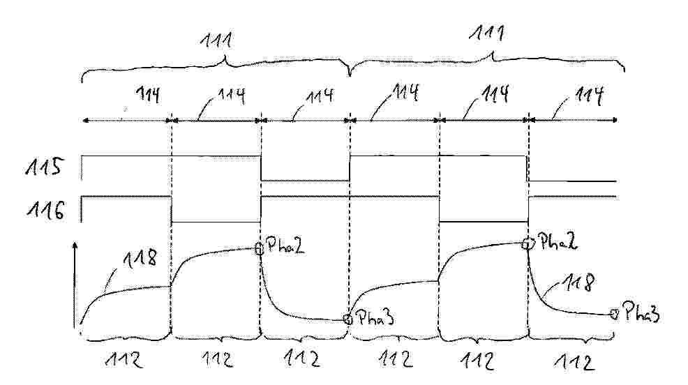
Die Erfindung betrifft ein Verfahren zum Überwachen einer Isolation zwischen zwei elektrischen Leitungen (102, 103), insbesondere elektrischen Hochvolt-Leitungen, und Masse (104) mittels einer Isolationsüberwachungs-Schaltung, wobei die Isolationsüberwachungs-Schaltung zwei Schalter (SWTestP, SWTestM) aufweist, das Verfahren aufweisend die folgenden Schritte: (a) Schalten der beiden Schalter (SWTestP, SWTestM) gemäß einer Schaltsequenz (111) bestehend aus einer Abfolge mehrerer Schaltzustände (112) der beiden Schalter (SWTestP, SWTestM); (b) Bestimmen eines Verlaufs einer vorgegebenen Größe (118, 119) während eines vorgegebenen Schaltzustands der mehreren Schaltzustände (112); (c) Extrapolieren zumindest eines Teils des Verlaufs, um einen Sättigungswert der vorgegebenen Größe (118, 119) für den vorgegebenen Schaltzustand zu erhalten; und (d) Bestimmen zumindest eines Isolationswiderstands (RisoPP, RisoPM, RisoLP, RisoLM) basierend auf dem Sättigungswert. Weiterhin betrifft die Erfindung ein entsprechendes Steuergerät und Computerprogramm.
Resumen de: WO2026089302A1
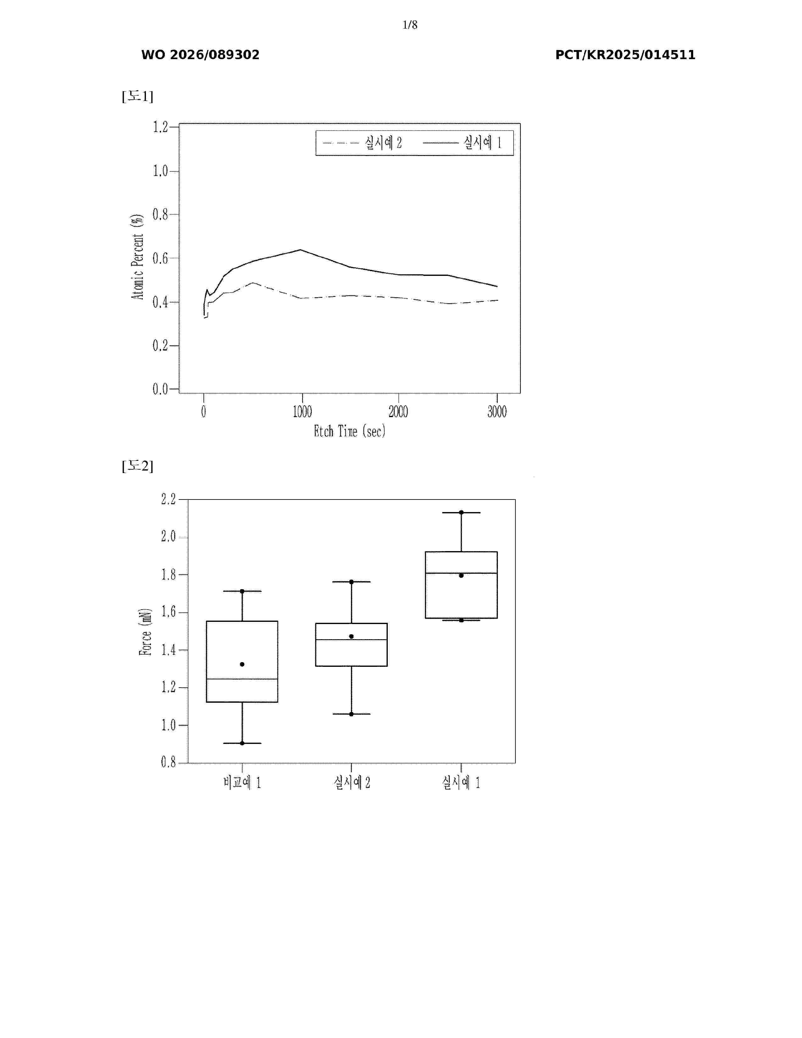
An embodiment of the present invention provides an electrode for a secondary battery, and a lithium secondary battery, the electrode including an electrode current collector and an electrode layer formed on one surface or both surfaces of the electrode current collector, wherein the electrode layer includes a lithium-based active material including: an over-lithiated manganese-based oxide in which a molar ratio of lithium to transition metals other than lithium is more than 1 and a molar content of manganese in the transition metals is 50 mol % or more; and a coating layer formed on a surface of the over-lithiated manganese-based oxide, and the coating layer includes Co in an amount of 3000 ppm to 8000 ppm on the basis of the total weight of the lithium-based active material.
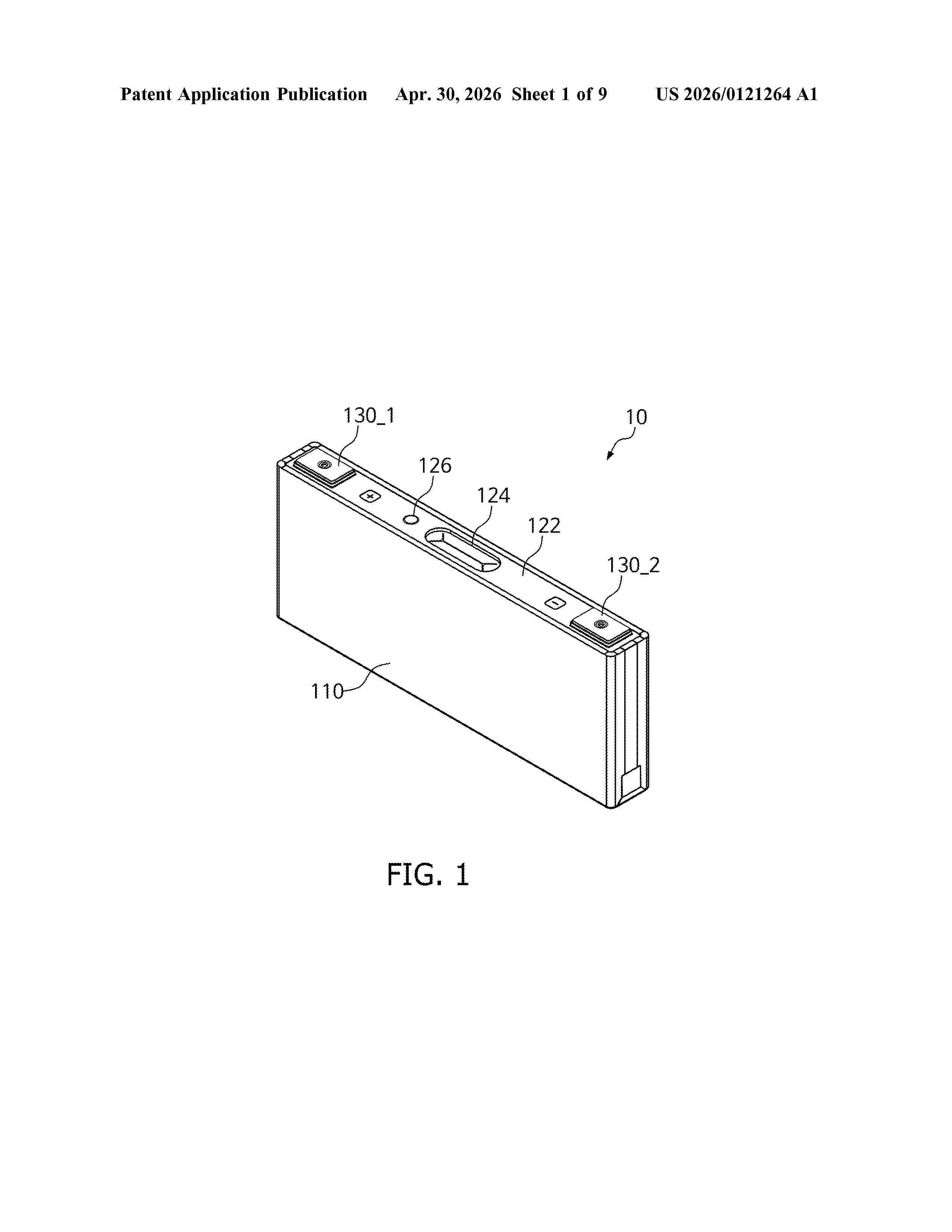
Resumen de: US20260121264A1
An electrode assembly includes an electrode plate including a coated portion where an active material is coated on sides of a composite substrate and an uncoated portion where the active material is not provided on the composite substrate. A conductor is coupled to the uncoated portion, and an insulating layer covers at least a part of each of the uncoated portion, the coated portion, and the conductor. The uncoated portion is coupled to a first side of the conductor, and the insulating layer is disposed on a second side of the conductor that is opposite to the first side.
Resumen de: WO2026088354A1
The purpose of the present invention is to provide a means with which it is possible to reduce resistance in a lithium secondary battery in which a solid electrolyte is used. The present invention relates to a lithium secondary battery comprising an electric power generation element that has: a positive electrode that has a positive electrode active material layer containing a positive electrode active material; a negative electrode that has a negative electrode active material layer containing a negative electrode active material; and a solid electrolyte layer that is interposed between the positive electrode and the negative electrode, and contains a solid electrolyte, wherein at least one of the positive electrode active material layer and the negative electrode active material layer is an electrode active material layer (x) that contains a solid electrolyte (B) and a compound (A) containing a group 6 transition metal element and a sulfur element, and the amount of the compound (A) that is contained in the layer is 0.03–3.0 mass% with respect to the mass of said layer.
Resumen de: US20260118185A1
Systems and methods for identifying a location of a thermal event detected by a temperature sensing tape are provided. In some embodiments, the temperature sensing tape can include a resistive ladder with parallel resistors between a plurality of temperature sensing elements to create voltage dividers, and unique analog output voltages can correspond to different ones of the plurality of temperature sensing elements being activated. In some embodiments, pulses injected into and reflected by the temperature sensing tape can be used detect a distance to a location where a triggering event is detected.
Resumen de: WO2026088546A1
Provided is a recycling method that makes it easy to increase the purity of metal to be recycled, and to recover the metal. The method for recycling batteries comprising an exterior body (10) and a battery body (20) accommodated in the exterior body (10) comprises a groove forming step (S31) for forming, in the exterior body, a groove (13) for breaking the exterior body (10), an initial breaking step (S33) for performing initial breaking at a weakened part (14) formed in the exterior body (10), and a breaking step for breaking the exterior body (10) at the groove (13), through the broken weakened part (14), wherein the battery is recycled by removing the battery body (20) from the exterior body (10).
Resumen de: WO2026089321A1
According to the present disclosure, an apparatus for manufacturing a battery cell may be provided, the apparatus comprising: a moving unit provided to transport a battery cell including a cell tab on which a barcode is displayed; and a recognition device which is disposed to face the movement path of the battery cell transported by the moving unit and provided to recognize the barcode, wherein the recognition device includes a guide unit provided to prevent the cell tab from bending by spraying air toward the cell tab.
Resumen de: WO2026086888A1
The present application relates to a battery cell, a battery, and an electric device. The battery cell comprises a casing, a cell core, a current collecting disc, and a cover plate. During assembly of the cover plate, the cover plate covers an opening of the casing, and a protruding portion of the cover plate extends into the casing from the opening. The side surface of the protruding portion abuts against positioning portions of a flange, so that the cover plate can be positioned in the radial direction. Since a welding region of the flange is located between every two adjacent positioning portions, a weld mark generated by welding the flange and the inner wall of the casing is also located between the two positioning portions. Moreover, since in the radial direction of the current collecting disc, the height of each weld mark is not higher than the height of each positioning portion, the weld mark can be prevented from abutting against the protruding portion under the support of the positioning portion, or the weld mark is just in contact with the protruding portion without affecting the abutting between the positioning portion and the protruding portion. Therefore, even if uneven weld marks are formed, the radial positioning accuracy of the cover plate is not affected, thereby improving the assembly accuracy of the battery cell.
Resumen de: WO2026089386A1
The present invention relates to a positive electrode active material comprising a lithium transition metal oxide in the form of single particles, wherein the lithium transition metal oxide contains 50 mol% or more of nickel in all transition metals excluding lithium, and shows a ratio of the rolling density (g/cm3) when rolled at 9 tons to the rolling density (g/cm3) when rolled at 2 tons (rolling density when rolled at 9 tons/rolling density when rolled at 2 tons) of greater than 2, fine particles having a particle diameter of 1 mu or less when rolled at 9 tons being contained in a content of 1 vol% or less.
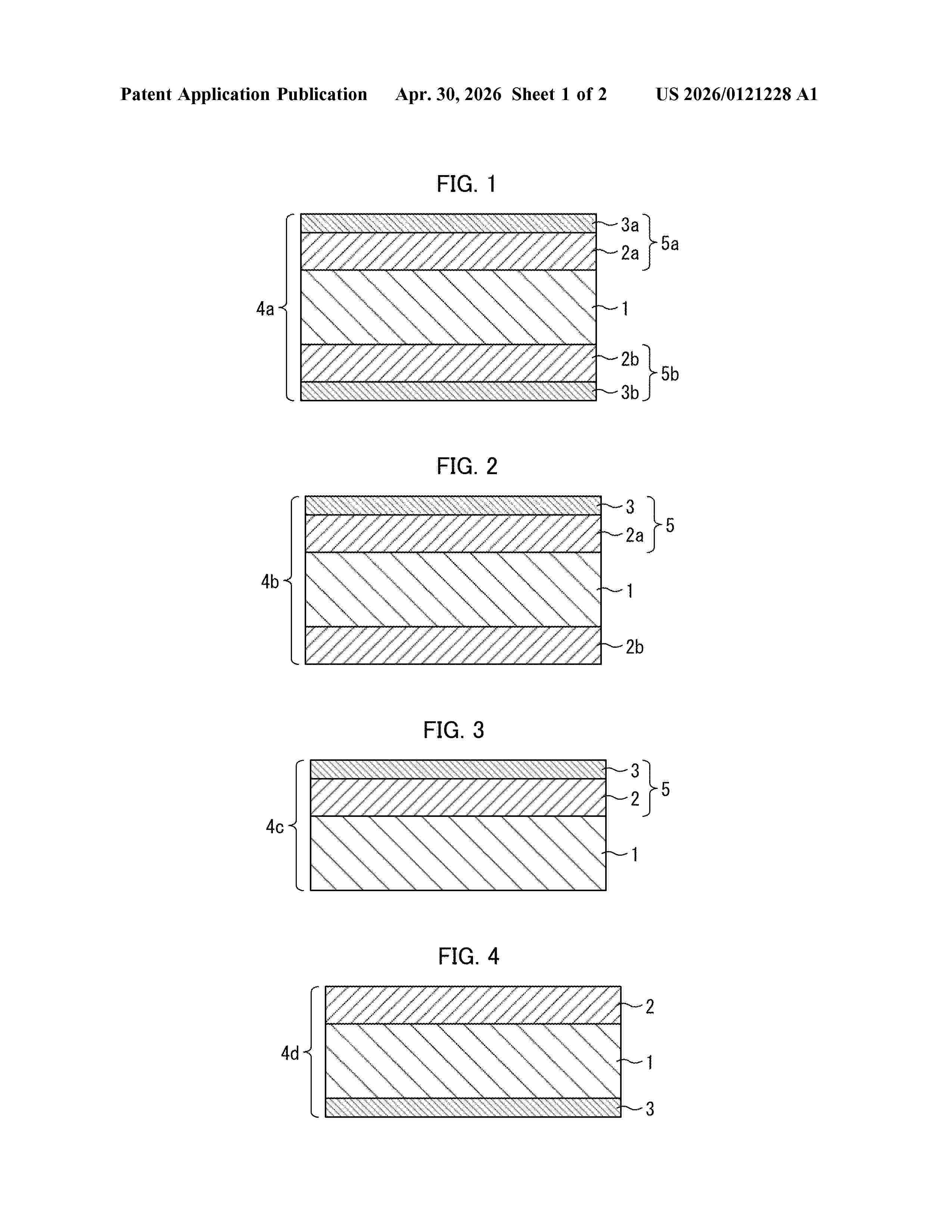
Resumen de: US20260121228A1
Provided is a porous layer for a nonaqueous electrolyte secondary battery superior in ion permeability under applied pressure. A porous layer for a nonaqueous electrolyte secondary battery in accordance with the present disclosure is a porous layer in which a product of a density of peaks Spd 1/μm2 and an arithmetic mean peak curvature Spc 1/μm is not less than 40 1/μm3, the density of peaks Spd and the arithmetic mean peak curvature Spc each being calculated from an image obtained by making observation of a surface of the porous layer by using a laser microscope.
Resumen de: WO2026090216A1
The present disclosure relates to paste compositions that contain a lead oxide, a carbon black comprising an alkali metal silicate impregnated thereon, a lignin source, barium sulfate, sulfuric acid, and optionally additional water. Electrodes, such as electrode plates, are prepared by first forming the paste composition, and then drying and curing the paste composition onto a metal current collector to form the electrodes. The electrodes can be utilized in lead acid batteries.
Resumen de: US20260121190A1
0000 It is to provide an electricity storage device in which a strength of an outer case is enhanced. The electricity storage device disclosed herein includes an electrode assembly including a positive electrode and a negative electrode, and includes an outer case that is configured to accommodate the electrode assembly and that is made of a metal. On the outer case, a fiber is continuously wound to cover an outer periphery side surface, so as to be aligned along a predetermined direction.
Resumen de: WO2026089402A1
A battery diagnosis apparatus and a battery diagnosis method are provided. The battery diagnosis method comprises the steps of: determining a reference temperature factor having a dependent relationship with the current operating mode of a battery, the mode corresponding to any one of a charging mode, a discharging mode and an idle mode; and diagnosing a temperature abnormality of the battery by using the reference temperature factor.
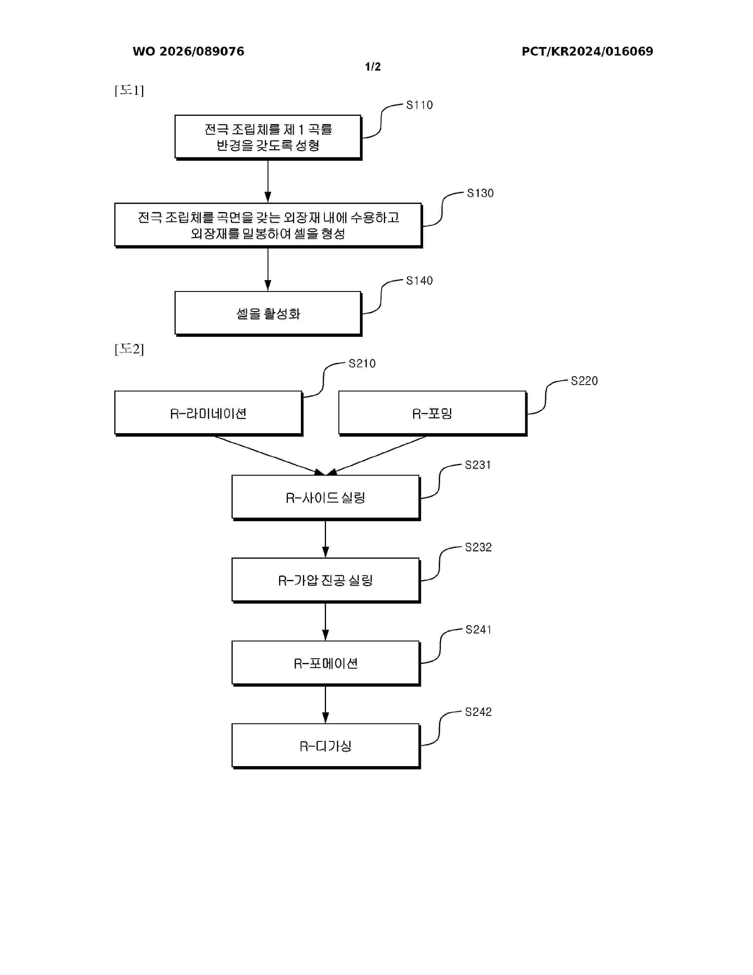
Resumen de: WO2026089076A1
A method for manufacturing a secondary battery according to the present invention comprises the steps of: forming an electrode assembly comprising a positive electrode, a negative electrode, and a separator interposed between the positive electrode and the negative electrode so as to have a first radius of curvature; forming a cell comprising the electrode assembly and an exterior material by accommodating the electrode assembly in an exterior material having a curved surface corresponding to the first radius of curvature and sealing the exterior material; and activating the cell, wherein the step of forming the cell and the step of activating the cell are performed in a state in which the cell is curved so as to have a second radius of curvature equal to or less than the first radius of curvature.
Nº publicación: WO2026089157A1 30/04/2026
Solicitante:
SAMSUNG SDI CO LTD [KR]
SOGANG UNIV RESEARCH & BUSINESS DEVELOPMENT FOUNDATION [KR]
\uC0BC\uC131\uC5D0\uC2A4\uB514\uC544\uC774 \uC8FC\uC2DD\uD68C\uC0AC
\uC11C\uAC15\uB300\uD559\uAD50 \uC0B0\uD559\uD611\uB825\uB2E8
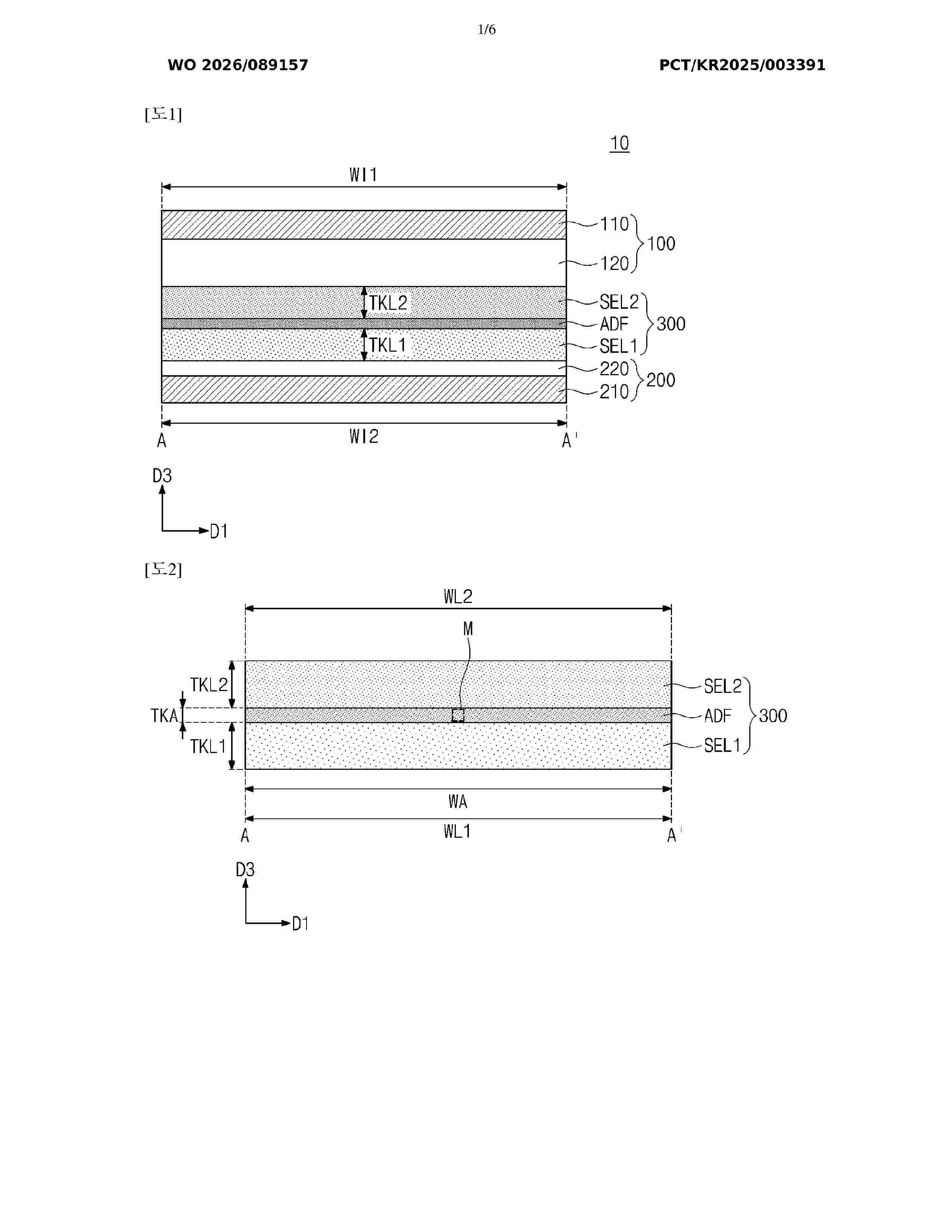
Resumen de: WO2026089157A1
The present invention relates to an adhesive film, an all-solid-state battery comprising same, and a method for manufacturing the all-solid-state battery. More specifically, included is a network structure of first and second linear polymers, wherein the first linear polymer comprises a first main chain and at least one first side chain, the second linear polymer comprises a second main chain and at least one second side chain, and the first and second side chains are ionically bonded to each other.
 BOPI
BOPI
 Sede Electrónica