Si deseas distinguir tus productos, servicios o ambos de los de otra empresa, es posible que necesites una marca o nombre comercial. Descubre qué son, en qué consiste su procedimiento de registro y qué implica.

Información sobre los plazos de presentación de solicitudes de transformación de marcas de la Unión Europea en marca nacional española. Más información


Si tienes un nuevo dispositivo, producto o procedimiento que resuelva un problema técnico o tenga una ventaja práctica, existen distintas formas de protegerlo en España y en otros países. Descubre cómo hacerlo.

¿Tu innovación reside en la estética, la ornamentación o la apariencia de tu producto? Protégela mediante un diseño industrial. Descubre qué derechos confiere el registro y cómo realizar la tramitación.

Las indicaciones geográficas protegen el nombre de un producto originario de una zona geográfica, a la cual le debe una determinada calidad, reputación u otra característica. Descubre qué son, en qué consiste su procedimiento de registro y qué beneficios conceden.

Las patentes publicadas en todo el mundo son una valiosa fuente de información científica, técnica y comercial.

Si eres emprendedor/a o una empresa y quieres potenciar y mejorar la rentabilidad de tu negocio protegiendo de forma adecuada los activos intangibles de tu organización, en este espacio encontrarás lo necesario.


 1509
resultados
1509
resultados
 Última actualización
17/03/2026 [07:16:00]
Última actualización
17/03/2026 [07:16:00]


 Resultados 625 a 650 de 1509

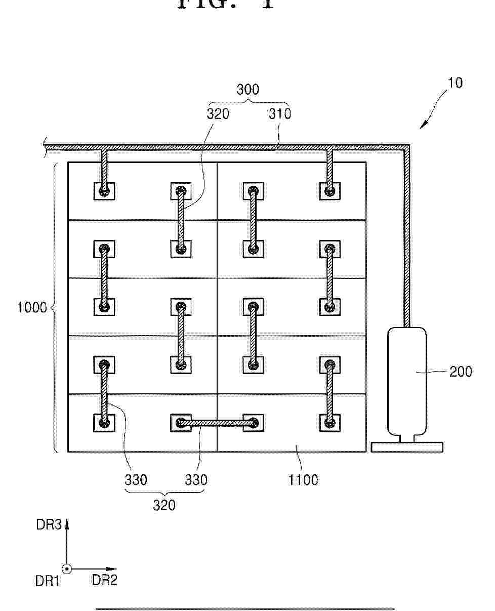
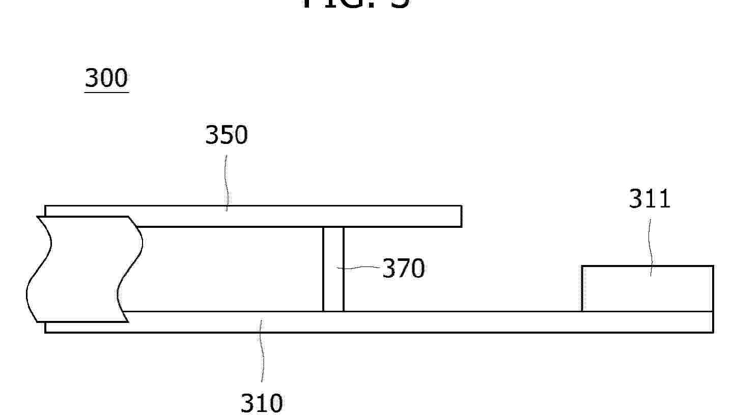
Resumen de: EP4708420A1
A secondary battery (300) including a housing (320) having an end wall and a sidewall, a positive electrode sheet, a first separator (210), a negative electrode sheet (220), a second separator (210), a first collector plate (310), and a first insulation film (230) is provided. An opening (330) is formed on one side of the sidewall facing away from the end wall. The positive electrode sheet, the first separator (210), the negative electrode sheet (220), and the second separator (210) are stacked and wound sequentially to form an electrode assembly (200) accommodated in the housing (320). The first collector plate (310) is disposed on one end of the electrode assembly (200) facing the opening (330), and the housing (320) is electrically connected to the negative electrode tab (221) through the first collector plate (310). The first insulation film (230) is wrapped around an outer periphery of the electrode assembly (200).

Resumen de: EP4708511A1
Disclosed is a battery pack having a stable fixing structure. The battery pack includes a pack case having a predetermined accommodation space; and a cell array stack including a plurality of cell array structures that are stacked in multi stages, the cell array stack having a case mounting portion fixed to at least one side wall of the pack case.
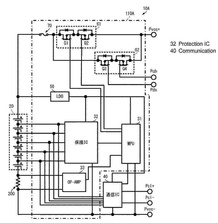
Resumen de: GB2643966A
A lithium ion battery pack (10) comprises: a lithium ion battery cell (20); a housing in which the lithium ion battery cell (20) is built and which is provided with a positive electrode terminal (Pvcc+), a negative electrode terminal (Pvcc-), and communication terminals (Pcl+, Pcl-); a BMS circuit (110) which is built in the housing and which includes a control unit that controls charging and discharging of the lithium ion battery cell (20); a communication IC (40) which causes terminal voltage values of the lithium ion battery cell (20) to output to the outside through the communication terminals (Pcl+, Pcl-) without passing through the BMS circuit (110); a first relay circuit (61) which, upon receiving a first control signal from the control unit of the BMS circuit (110), conducts or cuts off power supply to the lithium ion battery cell (20) through the positive electrode terminal (Pvcc+) and the negative electrode terminal (Pvcc-); an LDO (51) which supplies power to the control unit; and an LDO(52) which supplies power to the communication IC (40) separately from the LDO (51).
Resumen de: EP4708494A2
An energy storage system includes a module unit comprising the plurality of battery modules. The plurality of battery modules each accommodates a plurality of cell units. Each of the plurality of cell units comprise a plurality of battery cells arranged in a first direction and are arranged in a second direction, perpendicular to the first direction. A pipe portion is connected to a fire extinguishing tank storing a fire extinguishing agent and extends into the module unit. The pipe portion includes a main pipe extending from the fire extinguishing tank and a sub-pipe branched from the main pipe. One end of the sub-pipe is connected to a first branch point of the main pipe, and another end of the sub-pipe is connected to a second branch point of the main pipe. The sub-pipe extends to pass through all the plurality of battery modules.
Resumen de: EP4708505A1
A battery pack according to embodiments of the present disclosure is provided. The battery pack includes a pack housing including a base plate and sidewalls; first and second cross-beams disposed on the pack housing, and spaced apart in a first direction parallel to a mounting surface of the base plate and extending in a second direction parallel to the mounting surface of the base plate; a battery cell assembly interposed between the first and second cross-beams; a lead coupled to the sidewalls and covering the battery cell assembly; and a reinforcing bracket coupled to the lead and extending along the first direction.
Resumen de: EP4708510A1
The present disclosure discloses an energy storage cabinet, including: a cabinet body and a base for supporting the cabinet body; the cabinet body is provided with an accommodating space, and a battery is accommodated in the accommodating space; the base includes two first beams which are opposite in a first direction, and two second beams which are opposite in a second direction; each first beam includes a first supporting portion, a middle connecting portion and a second supporting portion which are sequentially connected in the second direction; one second beam is connected between the two first supporting portions which are opposite in the first direction; the other second beam is connected between the two second supporting portions which are opposite in the first direction; fork through holes are respectively formed in each first supporting portion and each second supporting portion; the fork through holes respectively formed in the first supporting portions define a first fork channel; the fork through holes respectively formed in the second supporting portions define a second fork channel; and the first fork channel and the second fork channel extend in the same direction.
Resumen de: EP4708544A1
Disclosed is a battery assembly. The battery assembly includes a case providing an inner space; a first battery array accommodated inside the case and including a plurality of battery cells stacked in a left and right direction; a second battery array accommodated inside the case and including a plurality of battery cells stacked in the left and right direction, the second battery array being stacked with the first battery array in the left and right direction; a first bus bar electrically connected to a front side of the first battery array and electrically insulated from the second battery array; and a second bus bar electrically connected to a front side of the second battery array and electrically insulated from the first battery array.
Resumen de: EP4709068A1
This application provides a power module and an energy storage system. The power module includes a housing, a connector, an inductor, a cold plate, and an air-liquid heat exchanger. The connector, the air-liquid heat exchanger, the cold plate, and the inductor are sequentially arranged inside the housing along a first direction. The housing includes a front plate and a rear plate. The front plate and the rear plate are oppositely arranged along the first direction. The connector is arranged between the air-liquid heat exchanger and the front plate along the first direction. The connector includes a cold plate inlet, a heat exchanger inlet, a cold plate outlet, and a heat exchanger outlet. Along a second direction, the cold plate inlet and the cold plate outlet are adjacently arranged, and the heat exchanger inlet and the heat exchanger outlet are adjacently arranged. Along a third direction, the heat exchanger inlet and one of the cold plate inlet and the cold plate outlet are adjacently arranged, and the heat exchanger outlet and the other one of the cold plate inlet and the cold plate outlet are adjacently arranged. The third direction, the second direction, and the first direction are perpendicular to each other. The power module in this application has a small size, and has good heat dissipation effect for various heat-generating components, and can reduce heat dissipation costs.
Resumen de: EP4708425A1
The manufacturing method of the nonaqueous electrolyte secondary battery is provided, which includes a construction step for constructing a secondary battery whose volume is equal to or more than at least 500 cm<sup>3</sup>, an initial electrically charging step for electrically charging the secondary battery until a SOC becomes 20% to 39%, a high temperature aging step for heating up and holding the secondary battery in a high temperature range, a room temperature aging step for cooling down the secondary battery being in the high temperature range and then holding the secondary battery in a room temperature range, and an inspecting resistance step for calculating an internal resistance of the secondary battery while the secondary battery is maintained in the room temperature range.
Resumen de: EP4708457A1
The present disclosure provides an energy storage system (10). The energy storage system (10) includes: a plurality of battery modules (40) each of which battery module (40) includes a plurality of battery cells (50); a first cooling system (100) that cools a first battery module set (42) among the plurality of battery modules (40); a second cooling system (102) that cools a second battery module set (44) among the plurality of battery modules (40); a central valve (300) that controls a flow of a refrigerant between the first cooling system (100) and the second cooling system (102); and a battery management system (200) that monitors and controls operations of the plurality of battery modules (40), the first cooling system (100), the second cooling system (102), and the central valve (300). The battery management system (200) controls the central valve (300) to control the flow of the refrigerant between the first cooling system (100) and the second cooling system (102) depending on whether an abnormality occurs in the operation of any one of the first cooling system (100) and the second cooling system (102).
Resumen de: EP4708527A1
An energy storage system includes a container having an accommodation space therein, at least one battery rack in the accommodation space inside the container, the at least one battery rack having a plurality of battery modules stacked thereon, an event detection device inside the container, at least one vent on an outer surface of the container, a nitrogen supply device that supplies nitrogen gas into the container, and a control unit electrically connected to the event detection device and the nitrogen supply device, the control unit driving the nitrogen supply device in response to the event detection device detecting an event.
Resumen de: EP4708539A1
The present disclosure provides a separator, a preparation method thereof, and a secondary battery using the same. The separator comprises a substrate layer and a hybrid coating applied to at least one surface of the substrate layer. In parts by weight, the hybrid coating comprises 25 parts to 45 parts of a component A, 13 parts to 16 parts of a component B, and 6 parts to 8 parts of a binder. The component A is cellulose with a characteristic peak for a molecular chain spacing at 2θ of 10° to 35°, and the component B is at least one selected from the group consisting of an oxide, a ceramic fiber, and a metal-organic framework. Compared to the prior art, the separator provided by the present disclosure adopts the hybrid coating in which cellulose with a characteristic peak for a molecular chain spacing at 2θ of 10° to 35° is adopted as the component A and contents of the component A, the component B, and the binder are controlled within the above ranges. As a result, the present disclosure effectively enhances the heat resistance of the separator and guarantees the high safety of batteries even when used under extreme conditions.
Resumen de: EP4708488A1
The present disclosure may provide a battery module including a plurality of battery cells having a storage portion and a sealing portion, respectively, and configured to be stacked on each other, a module case configured to store the plurality of battery cells in an inner space, and a pressing member positioned to face at least one surface of a terrace portion where an electrode lead is located in the sealing portion of the battery cell, and configured to pressurize the terrace portion when internal pressure inside the battery cell increases.
Resumen de: EP4708461A1
The present technology provides a battery pack including a pack housing including a bottom plate with a first cooling channel and a top plate with a second cooling channel, and a battery assembly between the bottom plate and the top plate of the pack housing, in which the battery assembly includes a separation structure including a plurality of cell accommodation spaces separated from each other in a first direction, and attached to the top plate via an upper thermally conductive adhesive layer, a plurality of battery cells accommodated in the plurality of cell accommodation spaces of the separation structure, and extending in a second direction perpendicular to the first direction, respectively, and a heat dissipation fin configured to thermally couple at least one of electrode leads of the plurality of battery cells to the bottom plate.
Resumen de: EP4708615A1
An integrated battery management system, including a first circuit board on which a wireless communication unit is mounted, and a second circuit board on which a microcontroller unit is mounted, the second circuit board being a predetermined distance above the first circuit board.
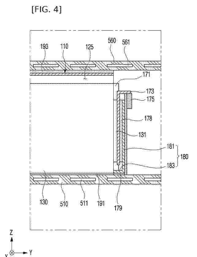
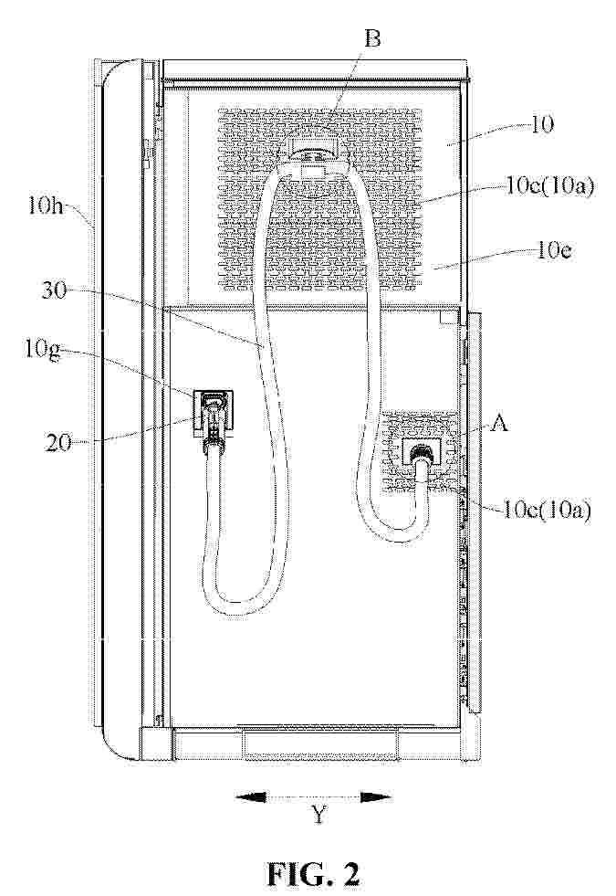
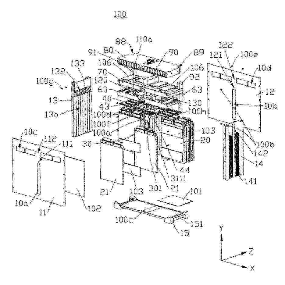
Resumen de: EP4707056A1
Embodiments of the present disclosure provide an energy storage apparatus, the energy storage apparatus including a cabinet body, an energy storage component, a charging gun and a cable, wherein air vents and a cable outlet are arranged on an outer surface of the cabinet body, the air vents include air inlets, and the air inlets are used for airflow entering the cabinet body; the energy storage component is arranged in the cabinet body; the charging gun is configured to be separable from the outer surface of the cabinet body; and a portion of the cable is positioned outside the cabinet body, one end of the cable is electrically connected to the charging gun, the other end enters the cabinet body through the cable outlet and is electrically connected to the energy storage component, and at least a portion of the cable passes through the air inlets.
Resumen de: EP4708454A1
This application discloses a battery module, a battery pack, and an electrical device. The battery module comprises a shell, a cell assembly, and a first heat dissipation element. The cell assembly is disposed in the shell. The cell assembly includes a plurality of battery cells. Each battery cell includes a cell housing and electrode terminals extends out of the cell housing. The first heat dissipation element is provided with a first heat dissipation channel. The first heat dissipation channel communicates with the outside. The first heat dissipation element is provided with a first heat dissipation recess. The first heat dissipation recess accommodates at least one cell housing. A part of each cell housing is disposed in the first heat dissipation recess. In this application, by disposing the first heat dissipation recess on the first heat dissipation element and disposing a part of the cell housing in the first heat dissipation recess, the heat of a battery cell can be directly conducted to the first heat dissipation element. The heat is taken away through the first heat dissipation channel, thereby shortening the heat dissipation path. The first heat dissipation recess can increase the heat dissipation area of the first heat dissipation element, thereby improving the heat dissipation efficiency, simplifying the structure of the battery module, and facilitating assembling.
Resumen de: EP4707661A1
A gas protection system, a gas protection method, and an energy storage system are provided. The gas protection system (10) includes: a gas transmission pipe (11) in communication with a sealed cabinet (1), where the gas transmission pipe is configured to input and output a protective gas to and from the sealed cabinet; a first detection module (12) disposed in the gas transmission pipe; and a gas supply module (13) configured to acquire gas parameters of the protective gas in the gas transmission pipe from the first detection module and supply a gas to the sealed cabinet based on the gas parameters. The gas protection system can mitigate the issue of thermal runaway in the sealed cabinet.
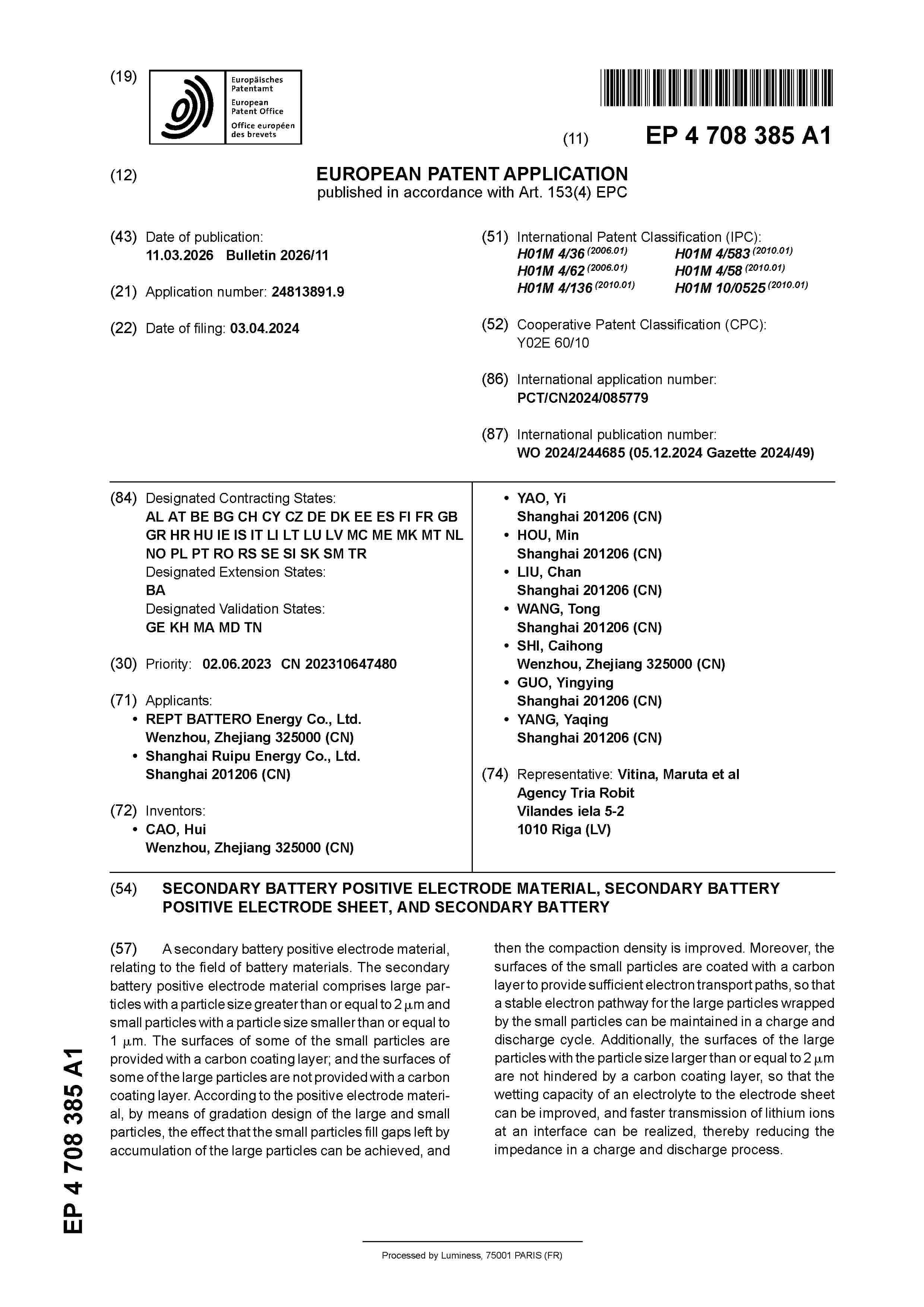
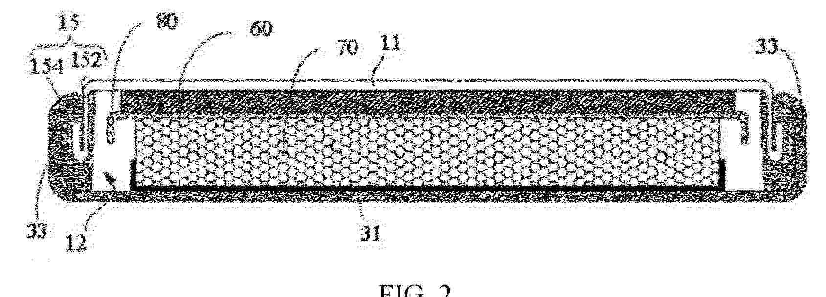
Resumen de: EP4708385A1
A secondary battery positive electrode material, relating to the field of battery materials. The secondary battery positive electrode material comprises large particles with a particle size greater than or equal to 2 µm and small particles with a particle size smaller than or equal to 1 µm. The surfaces of some of the small particles are provided with a carbon coating layer; and the surfaces of some of the large particles are not provided with a carbon coating layer. According to the positive electrode material, by means of gradation design of the large and small particles, the effect that the small particles fill gaps left by accumulation of the large particles can be achieved, and then the compaction density is improved. Moreover, the surfaces of the small particles are coated with a carbon layer to provide sufficient electron transport paths, so that a stable electron pathway for the large particles wrapped by the small particles can be maintained in a charge and discharge cycle. Additionally, the surfaces of the large particles with the particle size larger than or equal to 2 µm are not hindered by a carbon coating layer, so that the wetting capacity of an electrolyte to the electrode sheet can be improved, and faster transmission of lithium ions at an interface can be realized, thereby reducing the impedance in a charge and discharge process.
Resumen de: EP4708504A1
The present invention provides a structure of a battery module including: a cell stack wherein a plurality of battery cells are stacked in widthwise direction, each of the plurality of battery cells having a pair of electrode leads protruding in upward direction; a frame having an open upper portion and accommodating the cell stack; and a resin having an insulating property and filling at least a portion of a space between the cell stack and the frame, and also provides a method of manufacturing the same.
Resumen de: EP4708503A1
The present invention provides: a structure of a battery module comprising: a plurality of battery cells stacked in widthwise direction, each of the plurality of battery cells having a pair of electrode leads protruding in upward direction; a frame having an open upper portion and accommodating the cell stack; and a resin having an insulating property and filling at least a portion of a space between the cell stack and the frame; and a method of manufacturing the same.
Resumen de: EP4708489A1
The present application provides a button battery. The button battery comprises: a first substrate, a first annular wall, and a sealing member. The first annular wall is arranged around a periphery of the first substrate and forms an accommodating cavity with the first substrate, and at least a part of the sealing member is located on a side, away from the accommodating cavity, of the first annular wall. A second housing includes a second substrate and a second annular wall. The second substrate is configured to cover and seal the accommodating cavity, and the second annular wall is connected to a periphery of the second substrate.
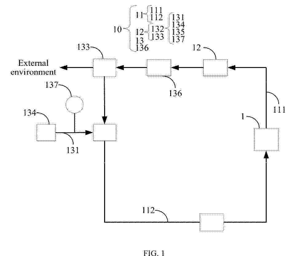
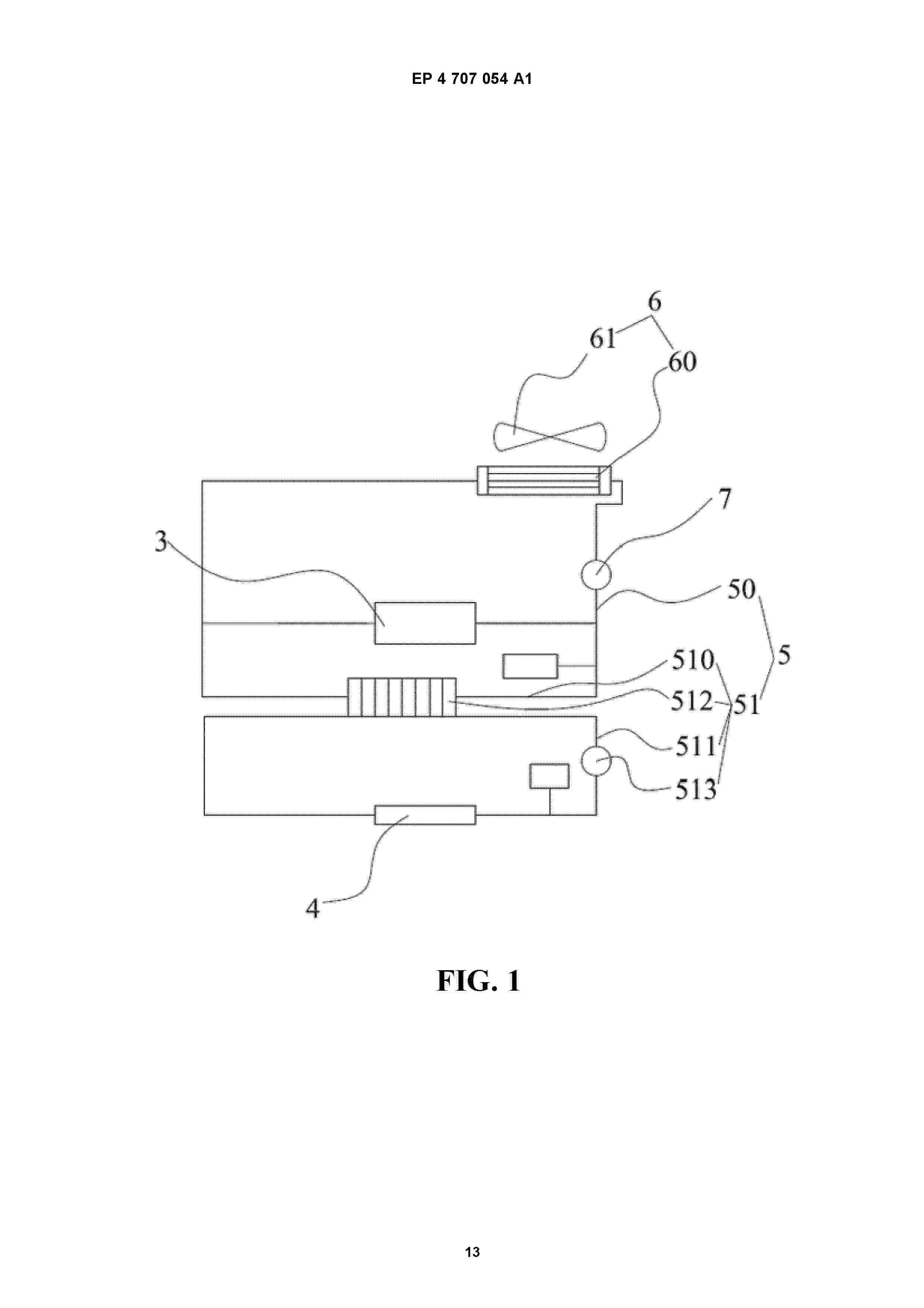
Resumen de: EP4707054A1
The present disclosure discloses an energy storage device, belonging to the technical field of batteries. The energy storage device comprises a cabinet, a battery pack, a charging converter, a charging connector, a cooling system and a first heat dissipation apparatus. The battery pack is installed inside the cabinet. The charging converter is electrically connected to the battery pack. The charging connector is electrically connected to the charging converter to transmit electric energy converted by the charging converter. The cooling flow channels of the charging connector and the cooling flow channels of the charging converter are arranged in the cooling system. The first heat dissipation apparatus is at least partially arranged in the cooling system to cool the charging connector and the charging converter. The cooling flow channels of the charging converter and the cooling flow channels of the charging connector in the embodiments of the present disclosure are both arranged in the cooling system, and the first heat dissipation apparatus is cooled by a fan to cool the charging converter and the charging connector.
Resumen de: EP4708455A1
Embodiments of the present disclosure provide a battery pack, an electrical apparatus, and an energy storage apparatus, which belong to the field of battery technologies. The battery pack includes a box, a battery cell, a thermal management component, a flange, a first connecting pipe, and a second connecting pipe. The box has an accommodating cavity and a mounting hole in communication with the accommodating cavity. The battery cell is located in the accommodating cavity. The thermal management component is located in the accommodating cavity to cool the battery cell. The mounting hole is used to avoid a temperature-regulating fluid entering and exiting the thermal management component. The flange covers the mounting hole. The flange is mounted on the box. The first connecting pipe is respectively connected to the flange and the thermal management component to provide the temperature-regulating fluid. The second connecting pipe is respectively connected to the flange and the thermal management component to discharge the temperature-regulating fluid. The flange spans the first connecting pipe and the second connecting pipe.
Nº publicación: EP4707053A1 11/03/2026
Solicitante:
CONTEMPORARY AMPEREX TECHNOLOGY CO LTD [CN]
CONTEMPORARY AMPEREX FUTURE ENERGY TECH SHENZHEN LIMITED [CN]
Contemporary Amperex Technology Co., Limited,
Contemporary Amperex Future Energy Technology (Shenzhen) Limited
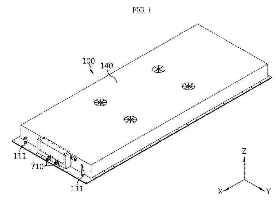
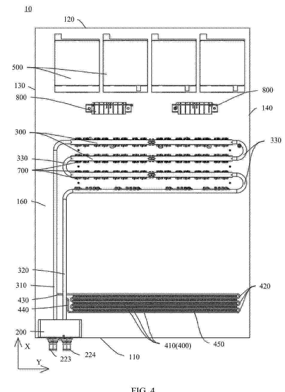
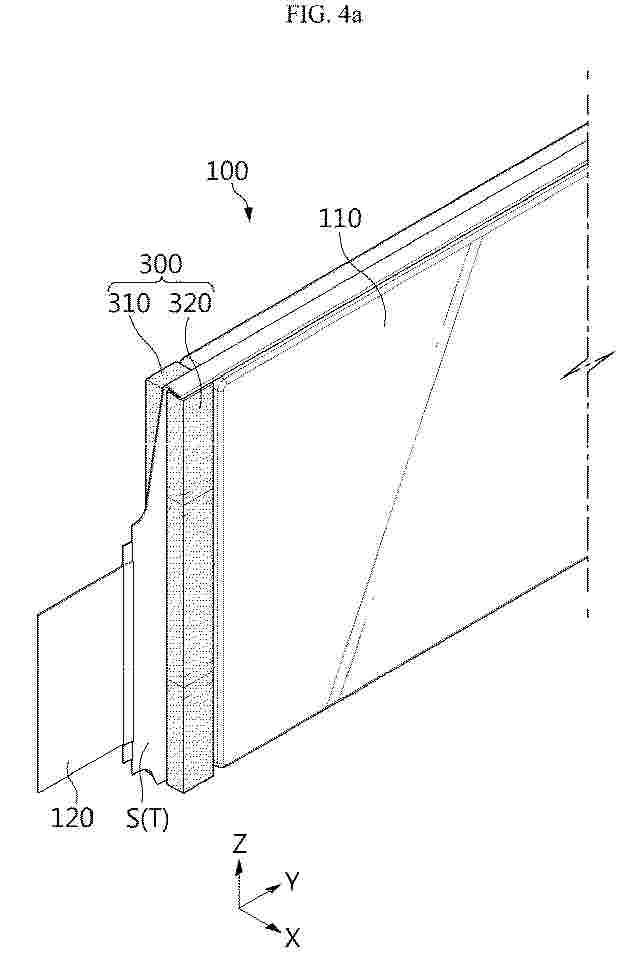
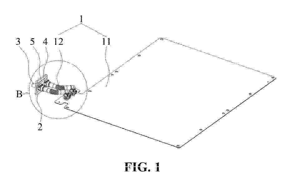
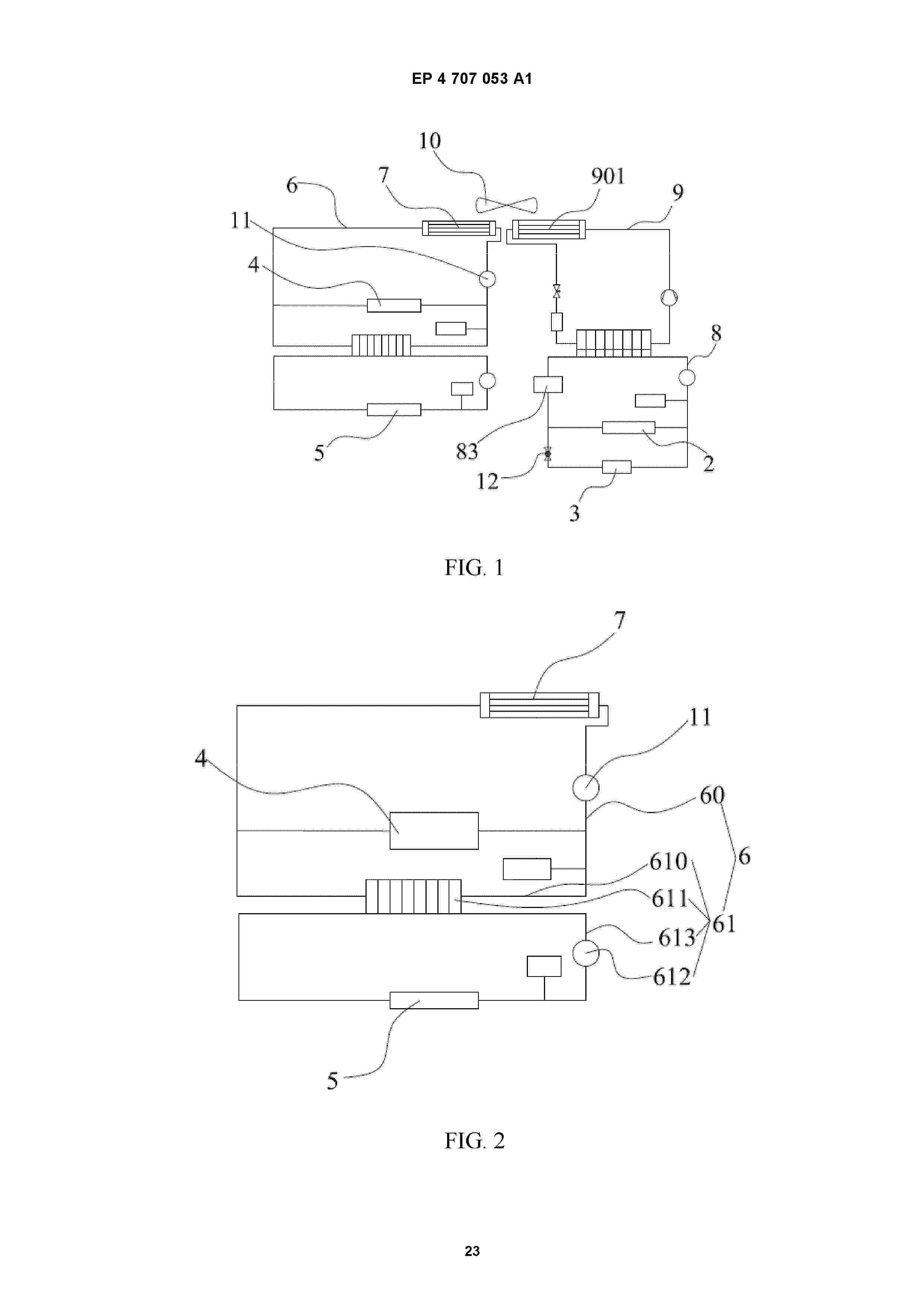
Resumen de: EP4707053A1
Embodiments of this disclosure provide an energy storage device and a temperature adjustment method for energy storage device, relating to the field of battery technologies. A battery pack installed inside a cabinet is electrically connected to an energy storage interface. A charging current converter is electrically connected to the battery pack. A charging connector is electrically connected to the charging current converter. A cooling system is configured to exchange heat with the charging current converter and the charging connector. A first heat dissipation apparatus is disposed in the cooling system. A temperature adjustment system is configured to exchange heat with the battery pack, and the cooling system and the temperature adjustment system are thermally separated. A second heat dissipation apparatus is disposed in the temperature adjustment system. A controller is configured to keep the cooling system off and turn on the temperature adjustment system in a first operating mode. The controller is configured to turn on the cooling system and the temperature adjustment system in a second operating mode. The controller is configured to keep the cooling system off and turn on the temperature adjustment system in a dormant mode.
 BOPI
BOPI
 Sede Electrónica