Si deseas distinguir tus productos, servicios o ambos de los de otra empresa, es posible que necesites una marca o nombre comercial. Descubre qué son, en qué consiste su procedimiento de registro y qué implica.

Información sobre los plazos de presentación de solicitudes de transformación de marcas de la Unión Europea en marca nacional española. Más información


Si tienes un nuevo dispositivo, producto o procedimiento que resuelva un problema técnico o tenga una ventaja práctica, existen distintas formas de protegerlo en España y en otros países. Descubre cómo hacerlo.

¿Tu innovación reside en la estética, la ornamentación o la apariencia de tu producto? Protégela mediante un diseño industrial. Descubre qué derechos confiere el registro y cómo realizar la tramitación.

Las indicaciones geográficas protegen el nombre de un producto originario de una zona geográfica, a la cual le debe una determinada calidad, reputación u otra característica. Descubre qué son, en qué consiste su procedimiento de registro y qué beneficios conceden.

Las patentes publicadas en todo el mundo son una valiosa fuente de información científica, técnica y comercial.

Si eres emprendedor/a o una empresa y quieres potenciar y mejorar la rentabilidad de tu negocio protegiendo de forma adecuada los activos intangibles de tu organización, en este espacio encontrarás lo necesario.


 1509
resultados
1509
resultados
 Última actualización
17/03/2026 [07:16:00]
Última actualización
17/03/2026 [07:16:00]


 Resultados 650 a 675 de 1509

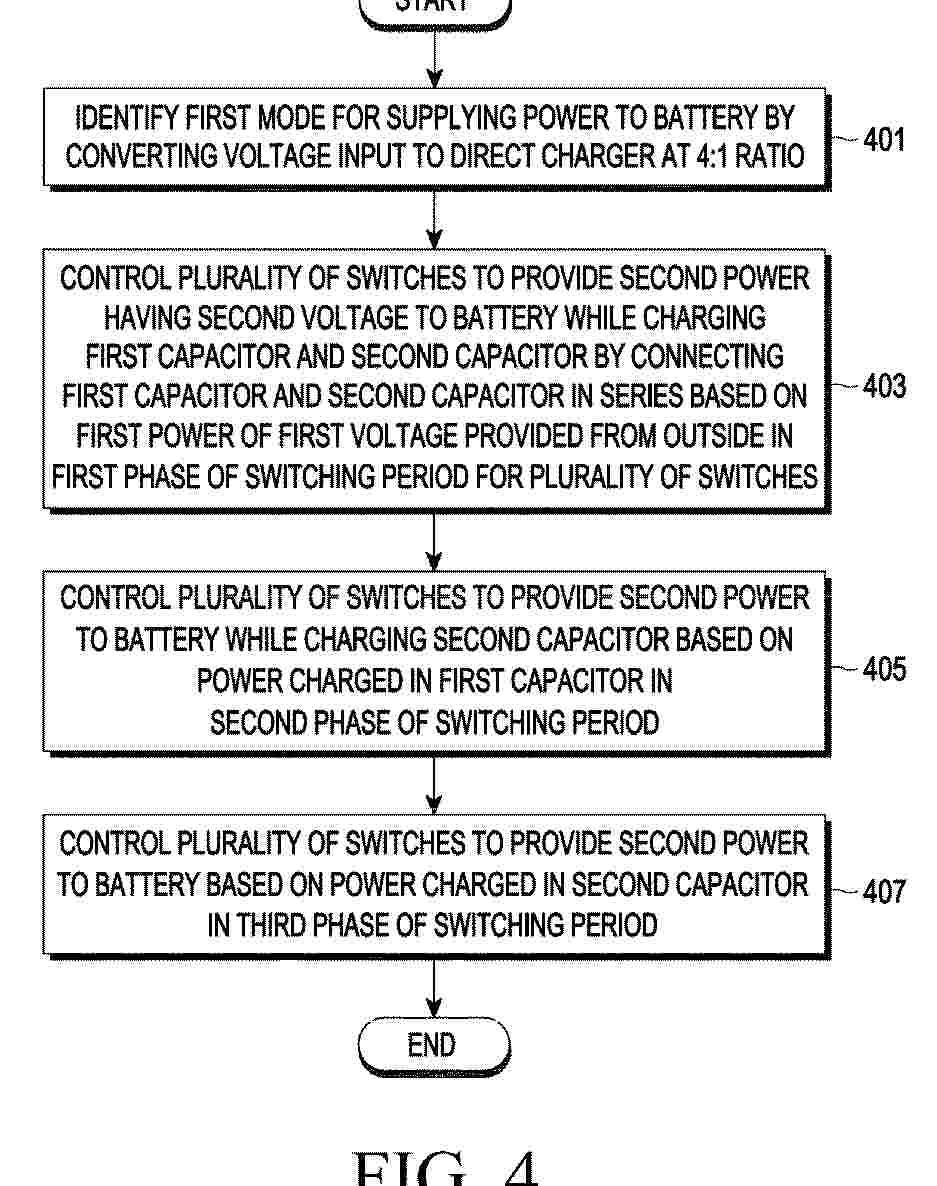
Resumen de: EP4708612A1
An electronic device according to an embodiment may comprise: a battery; a direct charger including a first capacitor, a second capacitor, and a plurality of switches; and a control circuit. The control circuit according to an embodiment may: identify a first mode in which a voltage input to the direct charger is converted at a 4:1 ratio and power is supplied to the battery; and control the plurality of switches at a first phase of providing second power having a second voltage which is 1/4 times a first voltage to the battery while charging a first capacitor and a second capacitor in series on the basis of first power of the first voltage received from the outside, a second phase of providing second power to the battery while charging the second capacitor with the power with which the first capacitor is charged, and a third phase of providing the second power to the battery on the basis of the power with which the second capacitor is charged, wherein a voltage which is twice the second voltage is applied to the first capacitor and the same voltage as the second voltage is applied to the second capacitor so that an output voltage is converted at a 4:1 ratio by only using two flying capacitors.

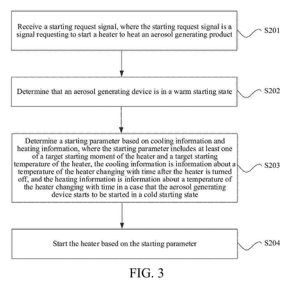
Resumen de: EP4706428A1
The present application provides a control method for an aerosol generating device and an aerosol generating device. The aerosol generating device comprises a heater for heating an aerosol generating product to generate an aerosol. The method comprises: receiving a starting request signal, the starting request signal being a signal for requesting to start a heater to heat the aerosol generating product; determining that an aerosol generating device is in a warm starting state; determining a starting parameter according to cooling information and heating information, the starting information comprising at least one of a target starting moment of the heater and a target starting temperature of the heater, wherein the cooling information is information of changes of the temperature of the heater along with time after the heater is turned off, and the heating information is information of changes of the temperature of the heater along with time when the aerosol generating device is started from a cold starting state; and starting the heater according to the starting parameter. The present application ensures a relatively good vaping taste.
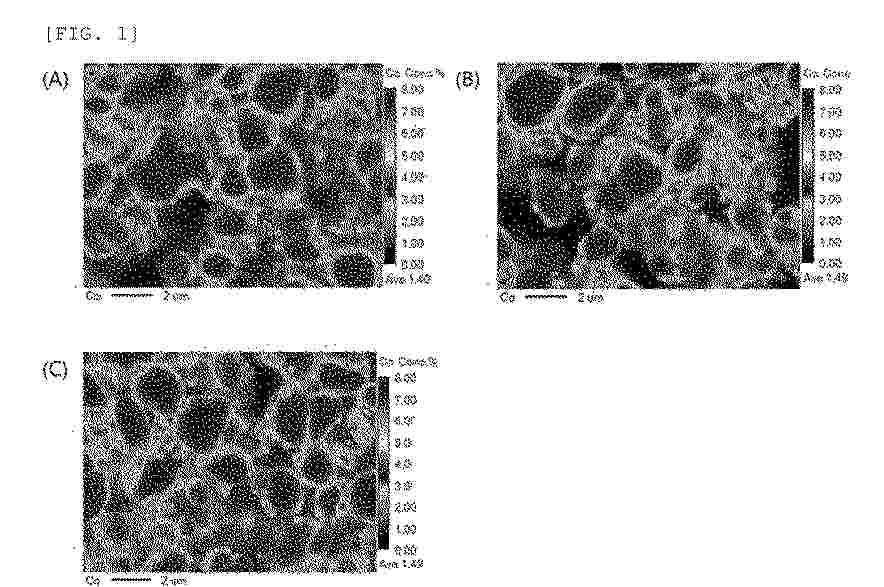
Resumen de: EP4708386A1
The present invention relates to a positive electrode active material capable of improving performance of a lithium secondary battery, the positive electrode active material including a lithium composite transition metal oxide in a form of a single particle; and a coating portion provided on the lithium composite transition metal oxide, wherein the coating portion comprises a first coating portion and a second coating portion, wherein the first coating portion is in a form of a discontinuously formed island, and the second coating portion is in a form of a continuously formed coating layer, wherein the first coating portion comprises boron (B) and optionally comprises at least one coating element selected from the group consisting of Co, Al, Ba, Ce, Cr, F, Mg, V, Ti, Fe, Zr, Zn, Si, Y, Nb, Ga, Sn, Mo, W, P, S, Sr, Ta, La, and Hf, the second coating portion comprises a compound having a composition represented by Formula 1 or 2 set forth in the specification, and an amount of boron (B) among total metals excluding lithium in the positive electrode active material is 0.1 mol% to 1.25 mol%, a method for preparing the positive electrode active material, and a positive electrode and lithium secondary battery including the positive electrode active material.
Resumen de: EP4708306A2
A system, device, method, and program for acquiring feature data for material composition information based on artificial intelligence are disclosed. The system may include a memory configured to store a first artificial intelligence (AI) model configured to output first feature data for composition information of a material and a second AI model configured to output second feature data for structure information of the material; and a processor configured to learn the first AI model and the second AI model. The processor may be configured to learn the first AI model based on the second feature data for the structure information of the material output by the second AI model, and/or to learn the second AI model based on the first feature data for the composition information of the material output by the first AI model.
Resumen de: EP4708547A2
The claimed invention relates to an energy storage device comprising: an electrode body; and an outer packaging that seals the electrode body, wherein the outer packaging is constituted by a film-like outer packaging member, the outer packaging includes a first sealing portion that is sealed by joining surfaces that face each other in a state in which the outer packaging member is wrapped around the electrode body, a base portion of the first sealing portion is formed at a boundary between a first surface and a second surface of the outer packaging, the first surface has a larger area than the second surface, and the first sealing portion does not overlap the first surface in a plan view, the outer packaging further comprising a lid body, and wherein the lid body: (A) is a metal molded article; (B) is a resin molded article; (C) has a plate shape; (D) is a member that is divided into a first portion and a second portion, and wherein a hole is configured to pass through the lid body; or (E) is a tray-shaped member having a bottom and a rectangular shape in a plan view.
Resumen de: EP4708460A2
The present disclosure relates to materials and systems to manage thermal runaway issues in energy storage systems. Exemplary embodiments include a thermal barrier material that includes multiple layers. The multilayer thermal barrier material includes at least one insulation layer, at least one compressible pad, and optional one or more layers that have favorable heat-dissipating properties, have favorable fire, flame and/or abrasion-resistance properties, have favorable performance for use as thermal barriers. The present disclosure further relates to a battery module or pack with one or more battery cells and the multilayer thermal barrier material placed in thermal communication with the battery cell
Resumen de: EP4708382A2
Provided is an anode material and a battery. The anode material includes a carbon matrix and an active substance, and at least a portion of the active substance is distributed in the carbon matrix; and surface cleanliness of the anode material is γ, and γ≥60%. The anode material and the battery provided in the present disclosure can alleviate cyclic attenuation of the anode material, reduce side reactions between the anode material and an electrolyte solution, and reduce a gas production phenomenon of the anode material, thereby comprehensively improving the capacity, expansion performance, and cycling performance of the anode material.
Resumen de: EP4708517A1
A sensing assembly includes a plurality of busbars and a plurality of sensing frames arranged along a first direction to support the plurality of busbars. The sensing frames includes a middle sensing frame and an outer sensing frame disposed on a first side of the middle sensing frame along the first direction. The middle sensing frame includes: a first peripheral surface facing toward one side in the first direction; a second peripheral surface disposed on an opposite side to the first peripheral surface and facing toward an opposite side in the first direction; a support surface connected with the second peripheral surface and facing toward one side in a second direction crossing the first direction; a guide protrusion protruding from the first peripheral surface toward the one side in the first direction; and a guide groove disposed where the support surface and the second peripheral surface are connected.
Resumen de: GB2643940A
A flexible lithium-ion battery comprising a cathode 110, an anode 112 and an electrolyte 120 comprising lithium ions contained within a flexible casing 118, wherein each of the cathode and the anode independently comprises a flexible current collector 122, 126 comprising a carbon-based fabric comprising a porous network of porous graphitic fibre of at least 85 wt% carbon, and an electroactive composition 124, 128 supported on the collector, at least partially infiltrated into the pores and comprising a lithium-intercalating electrode material and a polymeric binder. The binder may be a polyurethane elastomer. The electroactive composition may comprise a conductive additive. The cathode material may be graphite, graphite composites with silicon, lithium metal or alloys, lithiated carbonaceous material or lithium titanate. The anode material may be a lithium metal oxide or phosphate. The current collectors may each comprise a terminal portion (Fig. 3, 708) of the fabric passing through the casing to provide an electrical terminal, wherein the casing is sealed by a polymeric sealant. A method of producing the battery wherein the electrodes are formed by applying a precursor slurry the electrode material and binder dissolved in solvent to the collectors, and drying. A flexible article comprising the battery.
Resumen de: GB2643924A
A compression pad for use in a battery assembly comprising a composite comprising: • 35 to 95 wt% silicone resin, which forms at least part of a silicone resin matrix; • 0 to 40 wt% optional additives • 5 to 65 wt% granules comprising fumed silica and an IR opacifier, said granules dispersed within the silicone resin matrix; one or both of said silicone resin matrix and said granules further comprise the optional additives. The granules comprise pores filled with the silicone resin to form impregnated granules. The granules are made by blending fumed silica, IR opacifiers and the optional additives and densifying the mixture by mechanical densification. The granules are then mixed with the silicone resin. Methods of forming te composite for use in the compression pad are also disclosed. In a preferred embodiment, commercially available granules comprising fumed silica and silicon carbide (SiC) as an IR opacifier may be used.
Resumen de: EP4708436A2
Interfacial films, which are both electronic conducting and ion conducting, for anode films are provided. The one or more protective films described herein may be mixed conduction materials, which are both electronic conducting and ion-conducting. The one or more protective films described herein may include materials selected from lithium transition metal dichalcogenides, Li<sub>9</sub>Ti<sub>5</sub>O<sub>12</sub>, or a combination thereof. The lithium transition metal dichalcogenide includes a transition metal dichalcogenide having the formula MX<sub>2</sub>, wherein M is selected from Ti, Mo, or W and X is selected from S, Se, or Te. The transition metal dichalcogenide may be selected from TiS<sub>2</sub>, MoS<sub>2</sub>, WS<sub>2</sub>, or a combination thereof. The lithium transition metal dichalcogenide may be selected from lithium-titanium-disulfide (e.g., LiTiS<sub>2</sub>), lithium-tungsten-disulfide (e.g., LiWS<sub>2</sub>), lithium-molybdenum-disulfide (e.g., LiMoS<sub>2</sub>), or a combination thereof.
Resumen de: EP4708515A2
Disclosed is a battery module with reinforced safety. The battery module includes a plurality of battery cells stacked in at least one direction; a module case configured to accommodate the plurality of battery cells in an inner space; and a heat dissipation member interposed between at least some of the plurality of battery cells and configured to at least partially contact the module case and transfer heat generated from the plurality of battery cells to the module case.
Resumen de: EP4706785A2
A fire monitoring apparatus according to an embodiment of the present disclosure is a device for monitoring a fire in an energy storage system, and includes a fire level determination unit configured to receive a smoke detection signal from a smoke sensor provided inside the energy storage system and determine a fire level according to the number of smoke sensors that detect the smoke; and a control unit configured to control an operation of at least one of an air conditioning unit, a fire extinguishing unit, a watering unit and a ventilation unit for the energy storage system as a fire suppression measure corresponding to the determined fire level.
Resumen de: EP4708429A2
The present technology relates to a positive electrode for a lithium secondary battery, and the positive electrode includes: a first positive electrode mixture layer contacting a positive electrode current collector; and at least one second positive electrode mixture layer arranged on the first positive electrode mixture layer. Herein, the first positive electrode mixture layer includes a first positive electrode active material and a first binder, and the second positive electrode mixture layer includes a second positive electrode active material and a second binder. Further, an average particle diameter (D<sub>50</sub>) the first positive electrode active material is smaller than an average particle diameter (D<sub>50</sub>) of the second positive electrode active material and is equal to or less than 3µm, and a specific surface area(BET) of the first positive electrode active material is equal to or greater than 3m<sup>2</sup>/g.
Resumen de: EP4708491A2
A battery module includes a buffer pad for preventing a damage to a battery cell, and a battery pack including the battery module. It is possible to prevent a damage to the outermost battery cell at the time of the swelling of battery cells by including a buffer pad, where first and second regions having different physical properties are positioned, in a region contacting the outermost battery cell of the battery cell laminate.
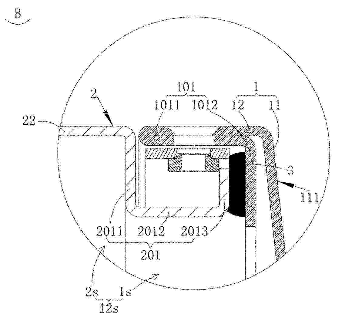
Resumen de: EP4708495A1
An energy storage device includes a first housing (1), provided with a first cavity (1s), the first housing (1) including a first abutting member (101) located in the first cavity (1s); a second housing (2), provided with a second cavity (2s) and a second abutting member (201), the second abutting member (201) being connected to the second housing (2); and a sealing element (3), located in the first cavity (1s), the sealing element (3) being connected between the first abutting member (101) and the second abutting member (201), where the first cavity (1s) and the second cavity (2s) communicate to form a first space (12s), and the first space (12s) is configured to accommodate a cell assembly and/or an electrical assembly (4).
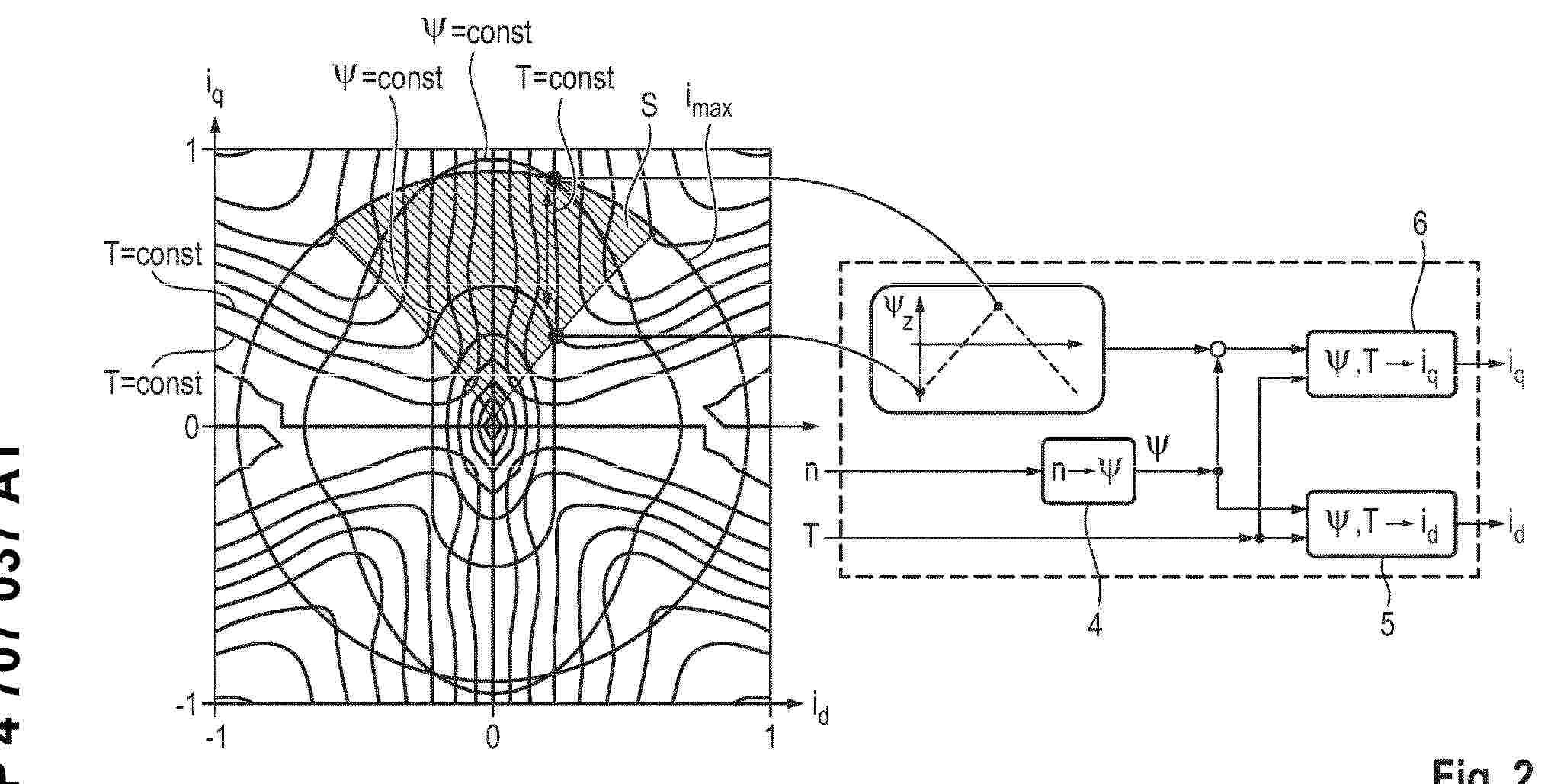
Resumen de: EP4707037A1
Die Erfindung betrifft ein Verfahren zum Heizen einer Fahrzeugbatterie (51) eines Kraftfahrzeugs (50), wobei das Kraftfahrzeug (50) einen Pulswechselrichter (2) und eine Elektromaschine (52) aufweist, wobei die Elektromaschine (52) als fremderregte Synchronmaschine (53) ausgebildet ist, wobei einer Drehzahl (n) der Elektromaschine (52) mittels einer Zuordnungsvorschrift (4) ein magnetischer Fluss (ψ) zugeordnet wird, wobei dem magnetischen Fluss (ψ) und einem Drehmoment (T) durch Zuordnungsvorschriften (5, 6) ein Längsstrom (id) und ein Querstrom (iq) zugeordnet wird, wobei ein periodischer Zusatzfluss (Δz) erzeugt wird, der nur der Zuordnungsvorschrift (6) für den Querstrom (iq) zugeführt wird, wobei die Modulation des periodischen Zusatzflusses (ψz) in einem Bereich (S) eines iq-id-Maschinenkennfeldes stattfindet, in dem die Linien konstanten Drehmomentes (T) nahezu vertikal verlaufen, sowie eine Anordnung (1).
Resumen de: EP4708440A1
An electrolyte includes a compound of formula Iand a compound of formula IIBased on a mass of the electrolyte, a mass percentage A of the compound of formula I satisfies 0.01% ≤ A ≤ 70%, and a mass percentage B of the compound of formula II satisfies 2.0% ≤ B ≤ 20%.
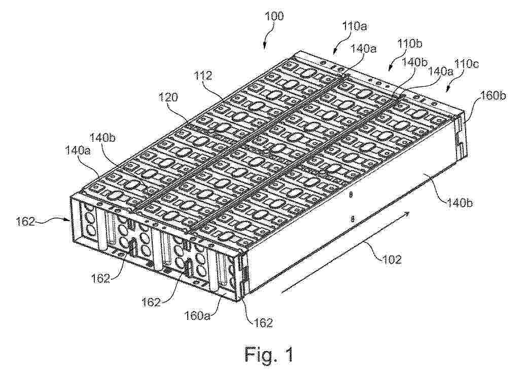
Resumen de: GB2643911A
A cell module 100 comprises module end plates 160a,160b, a first cell stack 110a and a second cell stack 110b, each cell stack comprising a series of cells 112 stacked along a longitudinal axis 102 and an end plate (130a,130b; Fig 2) at each end. The end plates apply compressive force along the longitudinal axis and define the stack length. The compressive force applied to the cell stacks is in a predetermined operable range. In use the module end plates are fixedly engaged with the corresponding stack end plates, and the first stack length is different to the second stack length (see figure 4). The stack end plates may be fixed to one another by intermediary support plates 140a,140b, which may extend along the longitudinal axis of the cell module. The end plates may have one or more engaging elements. The predetermined compressive force may be between 1-10,000 Newtons. Mount portions 162 of the module end plate may engage each of the stack end plates. There may also be a third cell stack which may have a different stack length to the first and second stack lengths. A further aspect is a method of manufacturing the cell module.
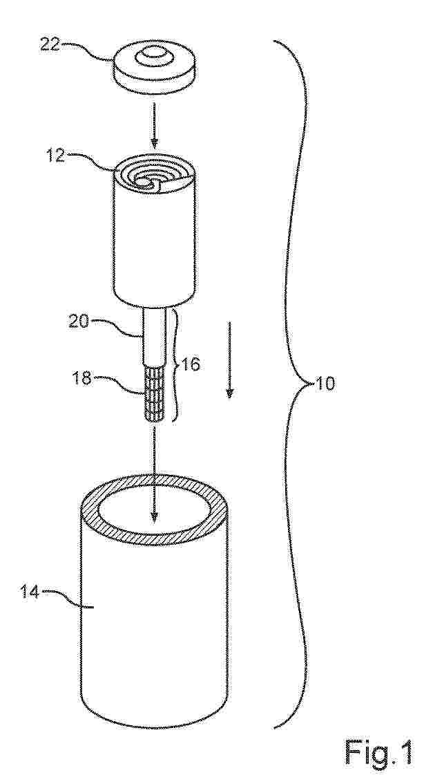
Resumen de: GB2643901A
A solid-state battery cell 10 for an electric energy storage device of an at least in part electrically operated motor vehicle, comprising a housing 14, wherein inside of the housing a jelly roll 12 is arranged and wherein the jelly roll comprises at least one mandrel 16 comprising a central polymer mandrel configured to increase radial pressure on the jelly roll. Part of the mandrel may be configured to receive an expansion agent - optionally a liquid substance, such as air - and may be a phase-change material. The mandrel may expand via an internal expansion mechanism, may comprise at least one composite material and may be at least partially hollow. The jelly roll may comprise a laminated stack of at least one anode layer (Fig. 2, 32), at least one solid-state electrolyte layer (Fig. 2, 30), at least one cathode layer (Fig. 2, 28) and at least one separator layer (Fig. 2, 26) rolled into a cylinder inside the housing. A method for manufacturing the battery cell.
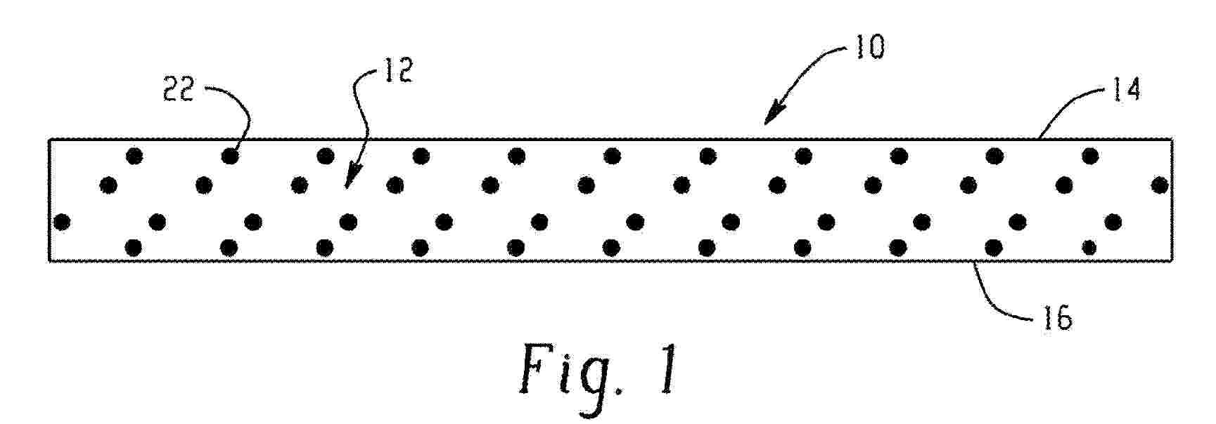
Resumen de: GB2643975A
A method of forming a thermal management sheet for a battery including cured polyurethane foam, the method including combining an active hydrogen-containing component including a polyol and an isocyanate component including a polyisocyanate to form an uncured polyurethane foam; and curing the uncured polyurethane foam to form the cured polyurethane foam, wherein the uncured polyurethane foam includes, based on a total weight of the uncured polyurethane foam, 3 to 68 weight percent of sodium borate, 0.1 to 7 weight percent of surfactant, and 0.001 to 9 weight percent of catalyst, wherein the cured polyurethane foam has a density of 12 to 35 pounds per cubic foot, and wherein the cured polyurethane foam has a thickness of 1 to 30 millimeters.
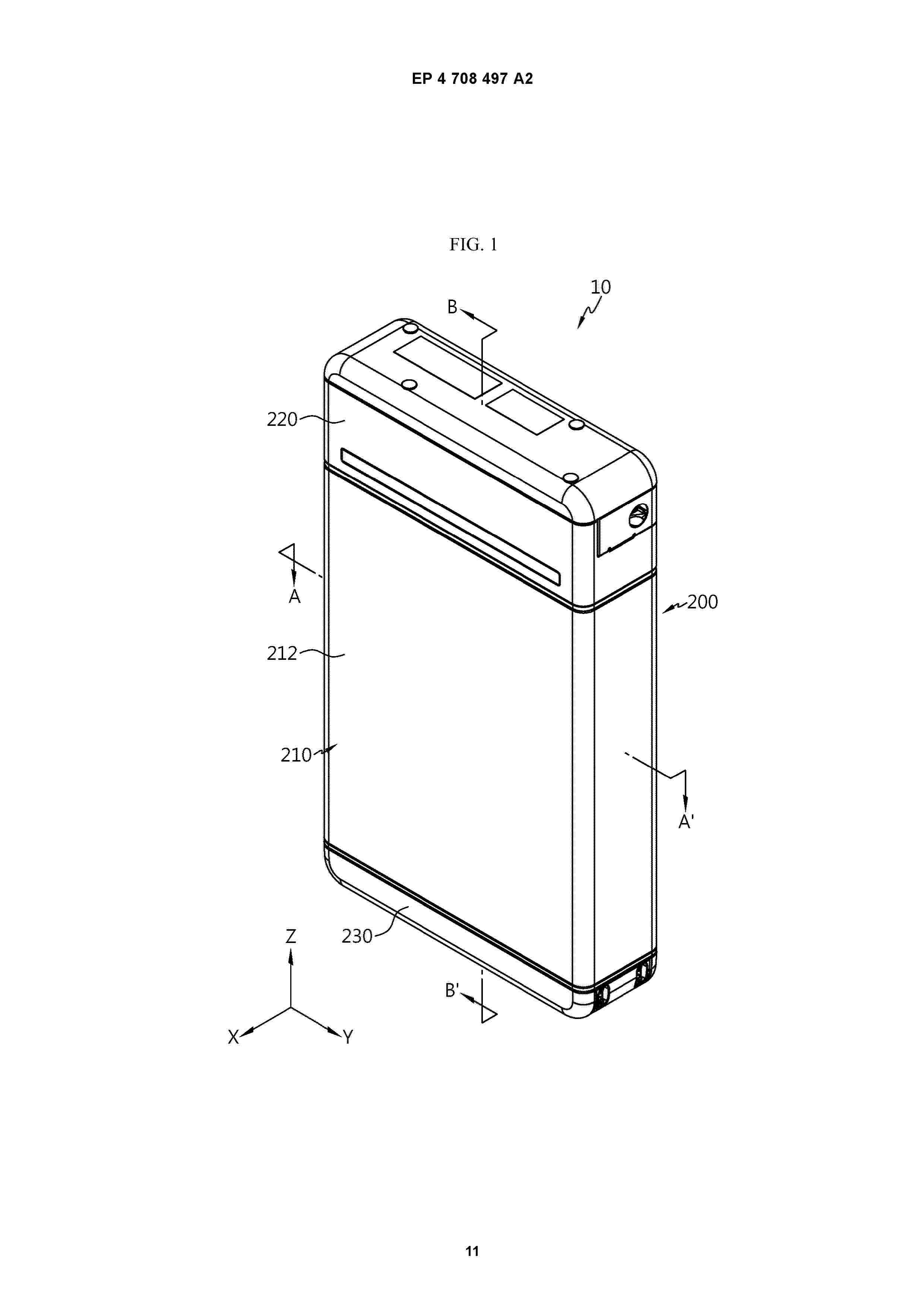
Resumen de: EP4708497A2
Disclosed are a battery pack configured to guide venting gas to be discharged in a desired direction when a thermal event occurs, and an energy storage system including the same.A battery pack according to one aspect of the present disclosure includes a cell assembly, a pack frame accommodating the cell assembly therein, and a venting guidance portion coupled to the pack frame and configured to cause an outlet, through which venting gas emitted from the cell assembly is discharged to the outside of the pack frame, to be formed at a coupling portion with the pack frame, which is at least partially weakened as the internal pressure of the pack frame increases due to the venting gas.
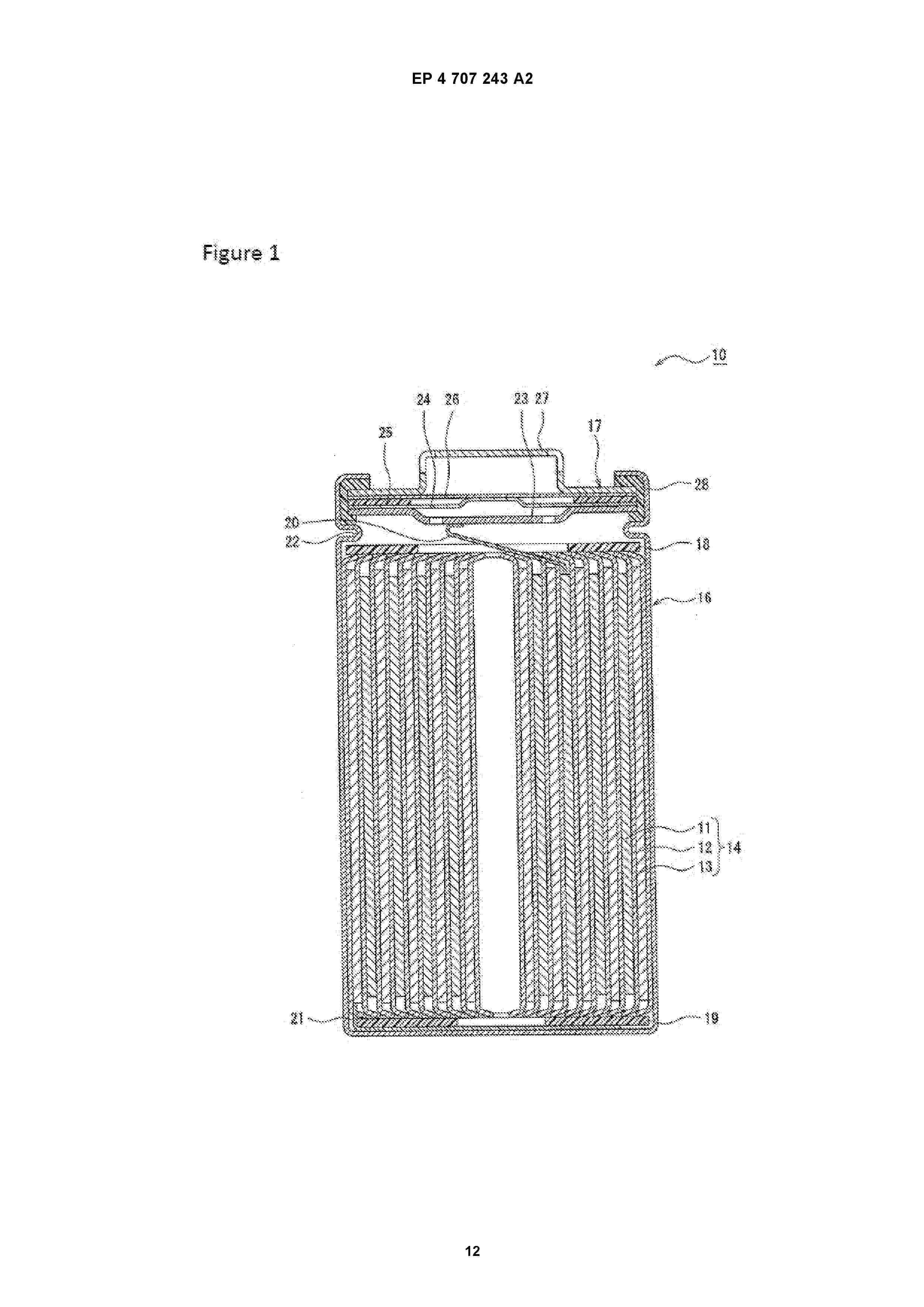
Resumen de: EP4707243A2
The present disclosure relates to a method of manufacturing a positive electrode active material for nonaqueous electrolyte secondary batteries that comprises a lithium transition metal composite oxide containing at least 80 mol% Ni with reference to the total number of moles of metal elements excluding Li, and that has B present on the particle surface of at least this composite oxide. Assuming that a particle having a particle diameter larger than the 70% volume-based particle diameter (D70) is denoted as a first particle and a particle having a particle diameter smaller than the 30% volume-based particle diameter (D30) is denoted as a second particle, the mole fraction of B, with reference to the total number of moles of metal elements excluding Li, in the first particle is larger than the mole fraction of B, with reference to the total number of moles of metal elements excluding Li, in the second particle.
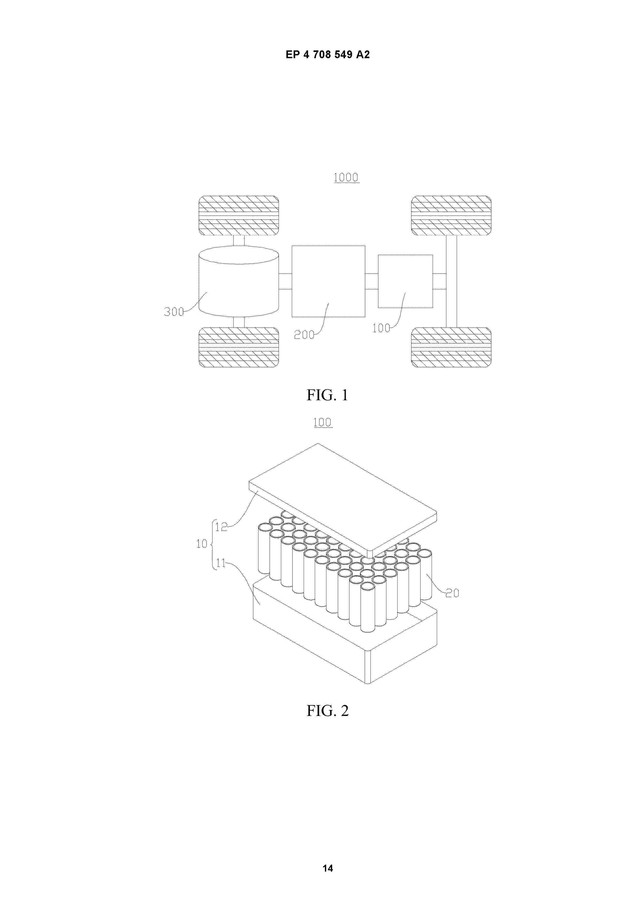
Resumen de: EP4708549A2
Embodiments of this application provide a battery cell (20), a battery (100), and an electric device, pertaining to the field of battery technologies. The battery cell (20) has a current collecting component (24) and two output poles with opposite polarities for outputting electrical energy. The current collecting component (24) includes two current collectors (241), an insulator (242), and a limiting structure (243). The two current collectors (241) are arranged opposite each other along a width direction of the current collecting component (24) and are configured to connect to the two output poles respectively. The insulator (242) is configured to connect the two current collectors (241) and is located at least partially between the two current collectors (241) in the width direction to insulate the two current collectors (241) from each other. The limiting structure (243) is configured to restrict the current collectors (241) from leaving the insulator (242) in the width direction. The two current collectors (241) in the current collecting component are connected by the insulator (242), and the two current collectors (241) are insulated from each other by the insulator (242). The limiting structure (243) restricts the current collecting component (24) from leaving the insulator (242) in the width direction of the current collecting component (24), so that the two current collectors (241) are not easily separated from the insulator, reducing the risk of the two current coll
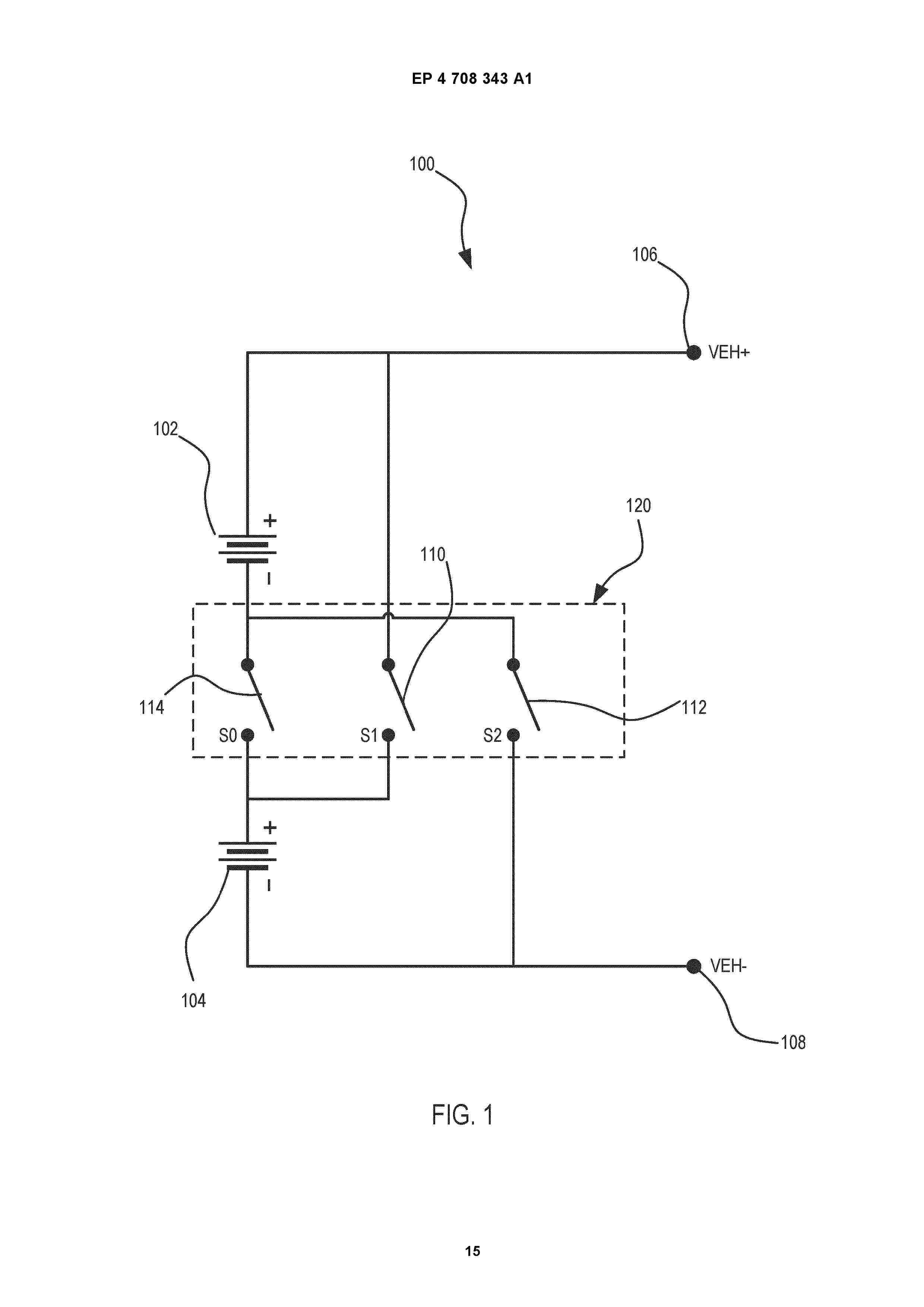
Nº publicación: EP4708343A1 11/03/2026
Solicitante:
SENSATA TECHNOLOGIES INC [US]
Sensata Technologies, Inc
Resumen de: EP4708343A1
In an embodiment, a multi-switch contactor assembly with a pre-charge system is disclosed. The multi-switch contactor further includes an array of switches and an actuator assembly configured to actuate each switch of the array of switches. In this embodiment, the array of switches includes a first switch configured to connect a first battery device to a circuit and a second switch configured to connect a second battery device to the circuit. The array of switches also includes a third switch configured to connect the first battery device and the second battery device in series to the circuit and a fourth switch configured to connect a pre-charge resistor to at least one of the first battery device and the second battery device.
 BOPI
BOPI
 Sede Electrónica