Si deseas distinguir tus productos, servicios o ambos de los de otra empresa, es posible que necesites una marca o nombre comercial. Descubre qué son, en qué consiste su procedimiento de registro y qué implica.

Información sobre los plazos de presentación de solicitudes de transformación de marcas de la Unión Europea en marca nacional española. Más información


Si tienes un nuevo dispositivo, producto o procedimiento que resuelva un problema técnico o tenga una ventaja práctica, existen distintas formas de protegerlo en España y en otros países. Descubre cómo hacerlo.

¿Tu innovación reside en la estética, la ornamentación o la apariencia de tu producto? Protégela mediante un diseño industrial. Descubre qué derechos confiere el registro y cómo realizar la tramitación.

Las indicaciones geográficas protegen el nombre de un producto originario de una zona geográfica, a la cual le debe una determinada calidad, reputación u otra característica. Descubre qué son, en qué consiste su procedimiento de registro y qué beneficios conceden.

Las patentes publicadas en todo el mundo son una valiosa fuente de información científica, técnica y comercial.

Si eres emprendedor/a o una empresa y quieres potenciar y mejorar la rentabilidad de tu negocio protegiendo de forma adecuada los activos intangibles de tu organización, en este espacio encontrarás lo necesario.


 1532
resultados
1532
resultados
 Última actualización
18/03/2026 [07:26:00]
Última actualización
18/03/2026 [07:26:00]


 Resultados 950 a 975 de 1532

Resumen de: WO2026049533A1
The present invention relates to a cathode active material, and a cathode and a lithium secondary battery that include same, the cathode active material comprising a lithium manganese iron phosphate-based compound and having a value of 5 or less as calculated by mathematical expression 1. When the cathode active material is applied to the lithium secondary battery, charge/discharge rate characteristics are excellent. Mathematical expression 1 │0.5∗LB-LD│∗103 In mathematical expression 1, LB is a b-axis length (unit: Å) of a crystal structure of the lithium manganese iron phosphate-based compound, and LD is a (020) d-spacing (unit: Å) between crystal structures of the lithium manganese iron phosphate-based compound.

Resumen de: WO2026048654A1
A lithium secondary battery comprises: an electrode group in which a band-shaped positive electrode and a band-shaped negative electrode are wound with a separator interposed therebetween; and a non-aqueous electrolyte. The positive electrode has a positive electrode current collector and a positive electrode mixture layer that is disposed on the positive electrode current collector. The positive electrode has one or more positive electrode current collector exposed portions at which the positive electrode current collector is exposed, and the one or more positive electrode current collector exposed portions include one or more positive electrode lead fixing portions to which a positive electrode lead is fixed. The negative electrode includes one or more negative electrode lead fixing portions to which a negative electrode lead is fixed. The negative electrode lead fixing portion faces one of the one or more positive electrode current collector exposed portions in a radial direction that is perpendicular to the winding axis, with the separator interposed therebetween.
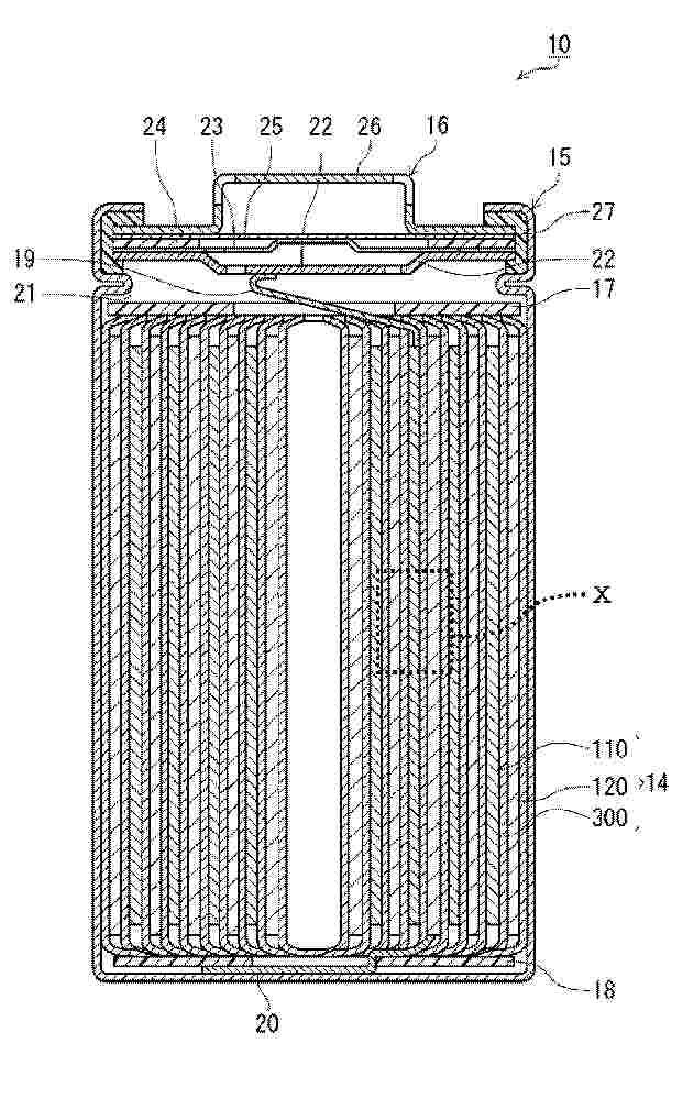
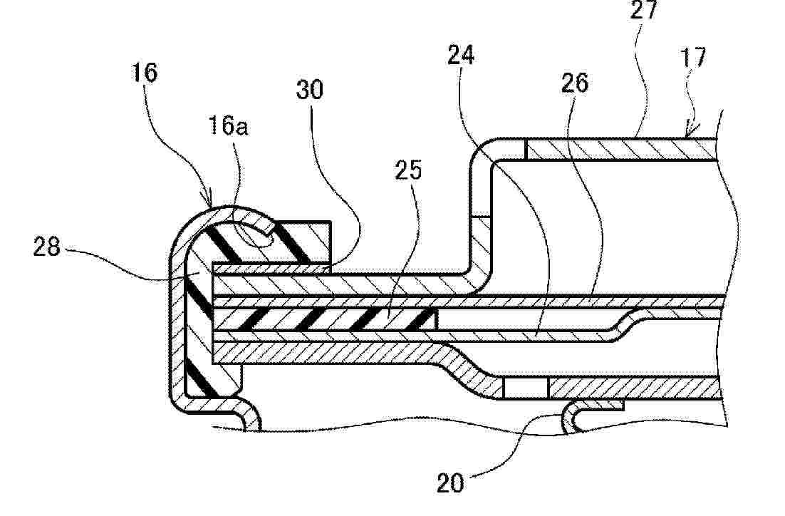
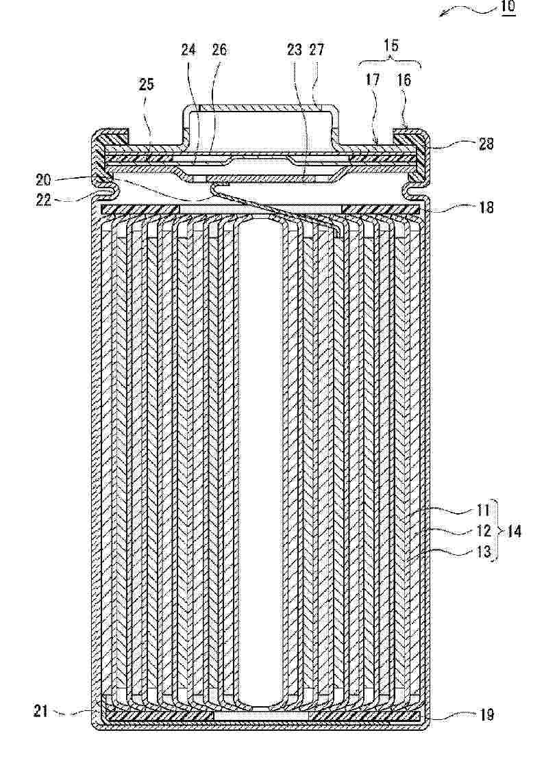
Resumen de: WO2026048436A1
A battery (10) comprises: a bottomed cylindrical outer can (16) that has an opening and accommodates an electrode body; a sealing body (17) that covers the opening of the outer can (16); a gasket (28) that is disposed between the outer can (16) and the sealing body (17); and a resistance layer (30) that is disposed between an end tip (16a) on the opening side of the outer can (16) and the upper surface of the sealing body (17) facing the end tip (16a), and that has a penetration resistance value of 0.05 Ω or more and 10 kΩ or less.
Resumen de: WO2026048424A1
Provided is a sheet-like object for a current collector capable of achieving both light weight and good battery characteristics at low cost. This sheet-like object for a current collector includes a base material layer, and layers containing organic resin A on both surfaces of the base material layer. The organic resin A is composed only of a polymer having LUMO of -0.5 eV or more.
Resumen de: WO2026048475A1
A nonaqueous electrolyte secondary battery (10) includes a positive electrode (11), a negative electrode (12), and a nonaqueous electrolyte, and is characterized in that: the positive electrode (11) has a positive electrode core and a positive electrode mixture layer provided on the positive electrode core; the positive electrode mixture layer contains a positive electrode active material; the positive electrode active material includes a first positive electrode active material having 《MK1》the shape of a secondary particle《/MK1》 formed by aggregation of primary particles, and a second positive electrode active material having 《MK1》the shape of a single particle《/MK1》; the content of the second positive electrode active material is 10 mass% or more and less than 40 mass% with respect to the total mass of the positive electrode active material; the nonaqueous electrolyte contains a heterocyclic compound including at least one electron withdrawing group R and a heterocycle; the electron withdrawing group R contains oxygen and/or nitrogen; and 《RA》the heterocycle《/RA》 contains nitrogen and sulfur.
Resumen de: WO2026045991A1
A dot-array coated battery separator, comprising a separator substrate and a polymer coating applied to the surface of at least one side of the separator substrate. The polymer coating comprises a plurality of crater-like dot-shaped coatings, each dot-shaped coating forming a frustoconical protruding structure having a raised periphery and a central depression. The dot-shaped coatings are arranged on the surface of the separator substrate to form a dot array. The crater structure of the dot-shaped coatings on the dot-array coated battery separator effectively reduces polymer accumulation at the coating points, and correspondingly lessens the impact of hot pressing on separator performance. As a result, the battery separator has good ion permeability, wettability, and gas permeability while satisfying bonding-strength requirements with the battery electrodes, thereby achieving a good performance balance. Further provided are a preparation method for the dot-array coated battery separator and a secondary battery comprising the dot-array coated battery separator.
Resumen de: WO2026046066A1
The present application relates to a battery, an electric device, an energy storage system, and a power station. During the structural design of the battery, the maximum size of conductive particles in an adhesive layer in a direction perpendicular to the thickness direction of the adhesive layer is controlled to be less than or equal to the adhesive thickness of the adhesive layer, and the projection size of the conductive particles in the thickness direction is reduced. Additionally, the minimum value of the distance between the conductive particles and the surface of the adhesive layer facing a battery cell is controlled to be greater than zero, so that each conductive particle does not exceed the surface of the adhesive layer facing the battery cell. By means of such design, the size and position distribution of the conductive particles in the adhesive layer are controlled, charge accumulation of the conductive particles in the adhesive layer is reduced, the probability of occurrence of partial discharge is effectively reduced, and the reliability of the battery is improved.
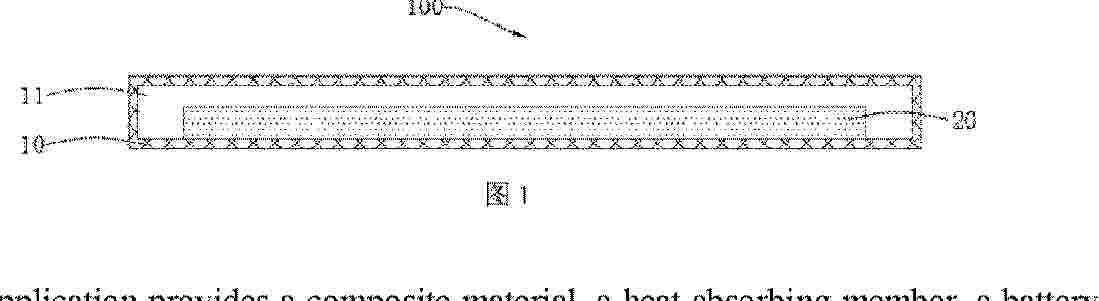
Resumen de: WO2026046111A1
The present application provides a composite material, a heat absorbing member, a battery assembly, and an electric device. The composite material comprises a polymer framework, an inorganic additive, and a phase change component. The inorganic additive comprises at least one of a hydrophilic aerogel and kaolin. In the composite material of the present application, the phase change component can improve the heat absorption performance of the composite material, and the inorganic additive can improve the thermal insulation performance of the composite material, such that the composite material has excellent heat absorption and thermal insulation effects, facilitating the use of the composite material in a battery assembly, and improving the use safety of battery cells.
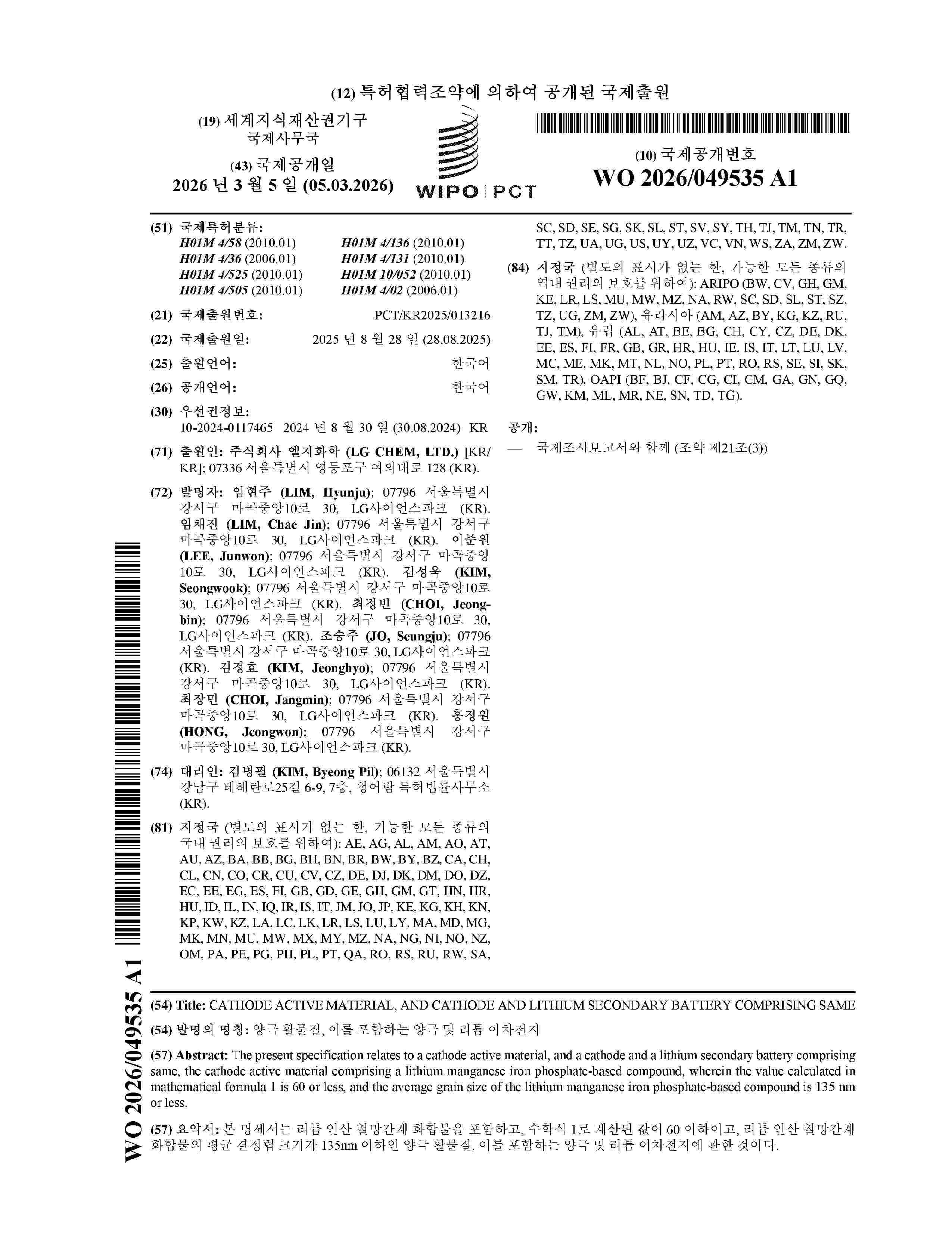
Resumen de: WO2026049535A1
The present specification relates to a cathode active material, and a cathode and a lithium secondary battery comprising same, the cathode active material comprising a lithium manganese iron phosphate-based compound, wherein the value calculated in mathematical formula 1 is 60 or less, and the average grain size of the lithium manganese iron phosphate-based compound is 135 nm or less.
Resumen de: WO2026049552A1
The present invention relates to a positive electrode active material, a method for preparing same and all-solid-state rechargeable batteries, the positive electrode active material comprising: a first positive electrode active material comprising a secondary particle that contains a first lithium nickel-based composite oxide and is formed by aggregation of a plurality of primary particles, a first coating layer that is positioned on the surface of the secondary particle and contains boron, and a second coating layer that is positioned on the first coating layer and contains lithium aluminate; and a second positive electrode active material which comprises a particle that contains a second lithium nickel-based composite oxide and is in the form of a single particle, a first coating layer that is positioned on the surface of the single particle and contains boron, and a second coating layer that is positioned on the first coating layer and contains lithium aluminate, and which has an average particle diameter smaller than the average particle diameter of the first positive electrode active material.
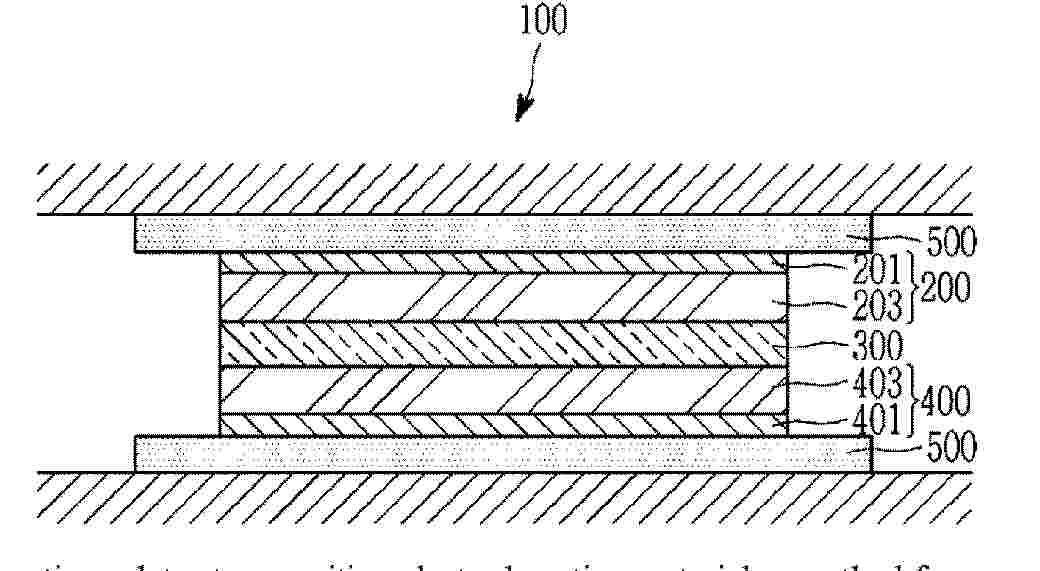
Resumen de: WO2026049529A1
The present invention may provide a battery pack comprising: cell arrays comprising a plurality of battery cells; a pack case assembly in which a plurality of pack cases configured to receive at least one of the cell arrays therein are arranged; and a venting valve configured to discharge venting gas generated from the battery cells to the outside, wherein the cell arrays are configured to be inserted into the pack cases in a first direction, and the pack cases are configured to be connected in a second direction perpendicular to the first direction.
Resumen de: WO2026049546A1
The present invention relates to a novel carbon nanotube having excellent electrical conductivity while exhibiting excellent storage and transportation efficiency, a method for manufacturing the carbon nanotube, a carbon nanotube dispersion, an electrode structure comprising the carbon nanotube, and a secondary battery comprising the carbon nanotube.
Resumen de: WO2026049415A1
The present invention relates to an electrode lead and an electrode lead manufacturing method, and more specifically, to: an electrode lead connected to an electrode assembly of a rechargeable battery which can be repeatedly charged and discharged; and an electrode lead manufacturing method for manufacturing the electrode lead. The electrode lead according to an embodiment of the present invention comprises: a first portion coupled to an electrode tab of an electrode assembly of a rechargeable battery; and a second portion connected to the first portion and protruding outward from a case of the rechargeable battery, wherein the first portion is narrower than the second portion, and a plating layer may be formed on at least part of the first portion and the second portion.
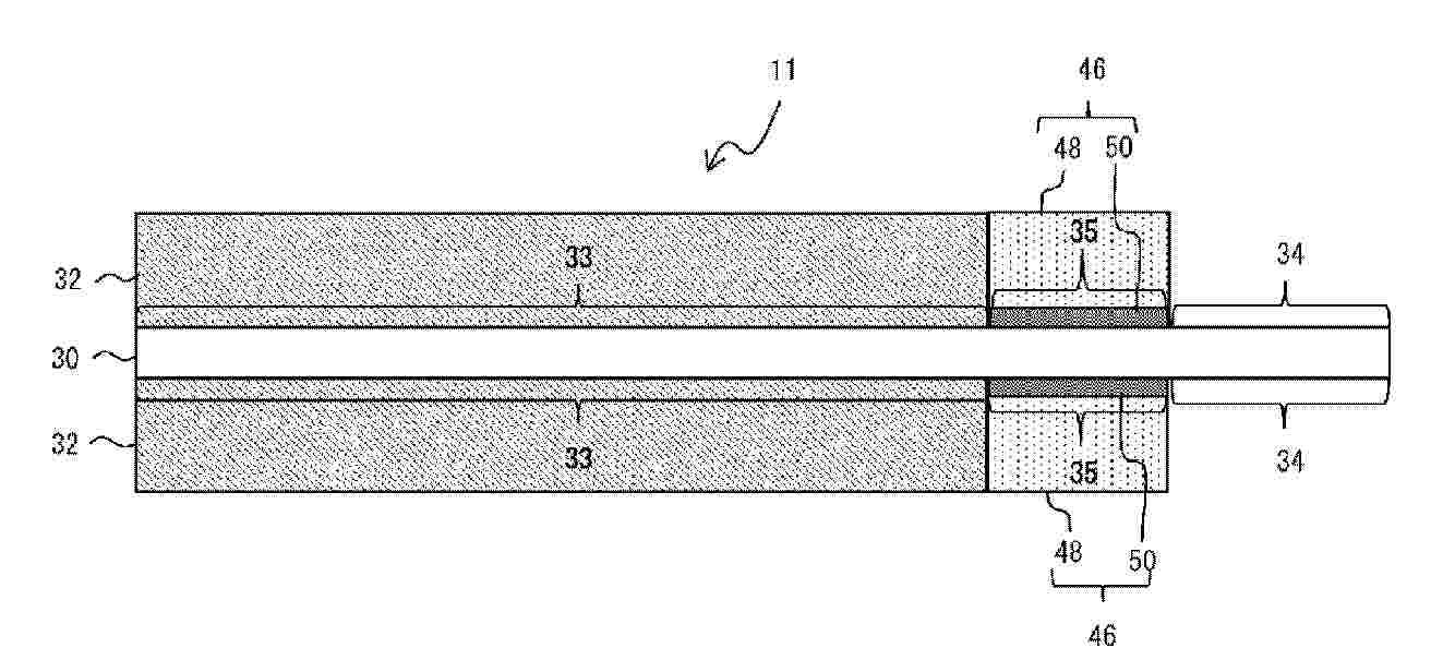
Resumen de: WO2026048578A1
The present invention is characterized in that: a positive electrode (11) is provided with a long positive electrode core body (30), and a positive electrode mixture layer (32) and a coating layer (46) which are disposed on the positive electrode core body (30); the positive electrode core body (30) comprises, at an edge in the short-side direction of the positive electrode core body (30), a positive electrode core body exposed part (34) which extends in the longitudinal direction of the positive electrode core body (30) and in which the positive electrode core body (30) is exposed, a positive electrode mixture layer disposition part (33) in which the positive electrode mixture layer (32) is disposed, and a coating layer disposition part (35) in which the coating layer (46) is disposed between the positive electrode core body exposed part (34) and the positive electrode mixture layer disposition part (33); the coating layer (46) has a protective layer (48) that comprises an inorganic filler and a first binder, and an adhesive layer (50) that comprises a second binder; the adhesive layer (50) is disposed on the positive electrode core body (32) in the coating layer disposition part (35); and the protective layer (48) is disposed on the adhesive layer (50).
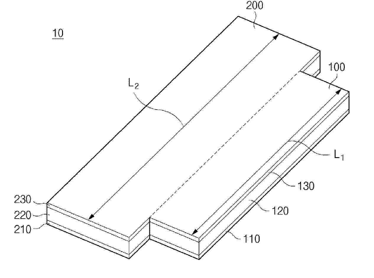
Resumen de: WO2026048714A1
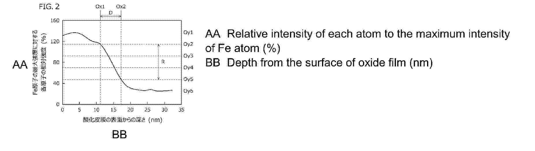
Provided is ferritic stainless steel foil that achieves both excellent adhesion to a thin film formed on an oxide film and excellent electrical characteristics. Ferritic stainless steel foil according to the present disclosure comprises a foil body and an oxide film formed on the surface of the foil body. The foil body includes ferritic stainless steel. The oxide film has an intermediate change region in oxygen concentration in the depth direction from the surface of the oxide film, the intermediate change region having a thickness of 3.0-10.0 nm.
Resumen de: WO2026048568A1
A non-aqueous electrolyte secondary battery comprises a positive electrode, a negative electrode, and a non-aqueous electrolyte, wherein the non-aqueous electrolyte secondary battery is characterized in that: the negative electrode has a negative electrode active material that contains a Si-containing material; the Si-containing material contains a composite material having a carbon phase and a silicon phase that is dispersed in the carbon phase; the non-aqueous electrolyte contains a heterocyclic compound that contains a heterocycle and at least one electron-withdrawing group R; the electron-withdrawing group R contains oxygen and/or nitrogen; and the heterocycle contains nitrogen and sulfur.
Resumen de: WO2026048563A1
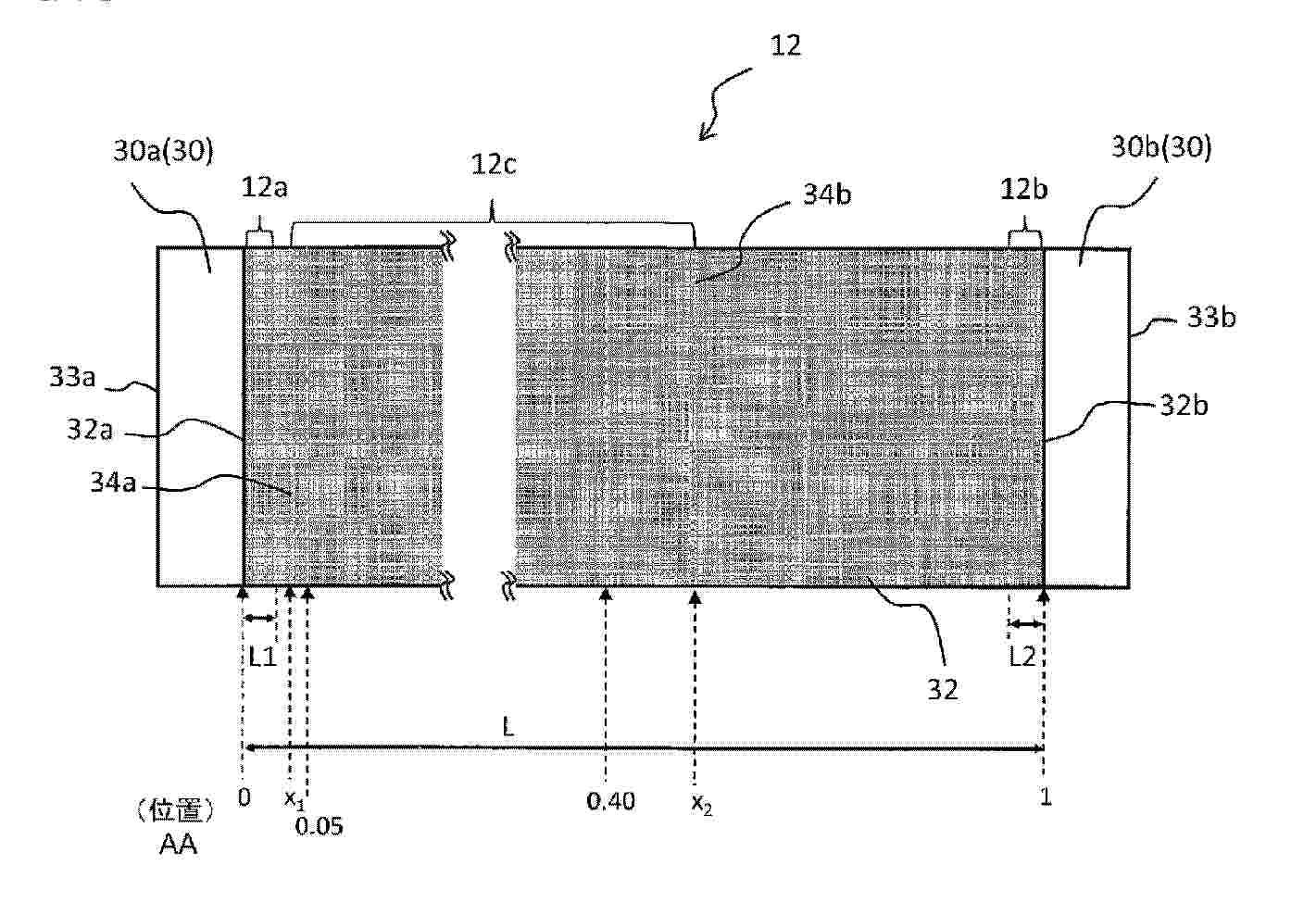
A secondary battery negative electrode (12) is characterized by comprising an oblong negative electrode core (30) and a negative electrode mixture layer (32) that is provided on the negative electrode core (30) and by having a first end region (12a) that is on one end (32a) side in the longitudinal direction of the negative electrode mixture layer (32), a second end region (12b) that is on another end (32b) side in the longitudinal direction of the negative electrode mixture layer (32), and a low expansion region (12c) that has a lower negative electrode plate charging expansion rate than the first end region (12a) and the second end region (12b), the low expansion region (12c) being at least at a position of at least 0.05 but less than 0.40 when the position of the one end (32a) in the longitudinal direction of the negative electrode mixture layer (32) is 0 and the position of the other end (32b) in the longitudinal direction of the negative electrode mixture layer (32) is 1.
Resumen de: WO2026046168A1
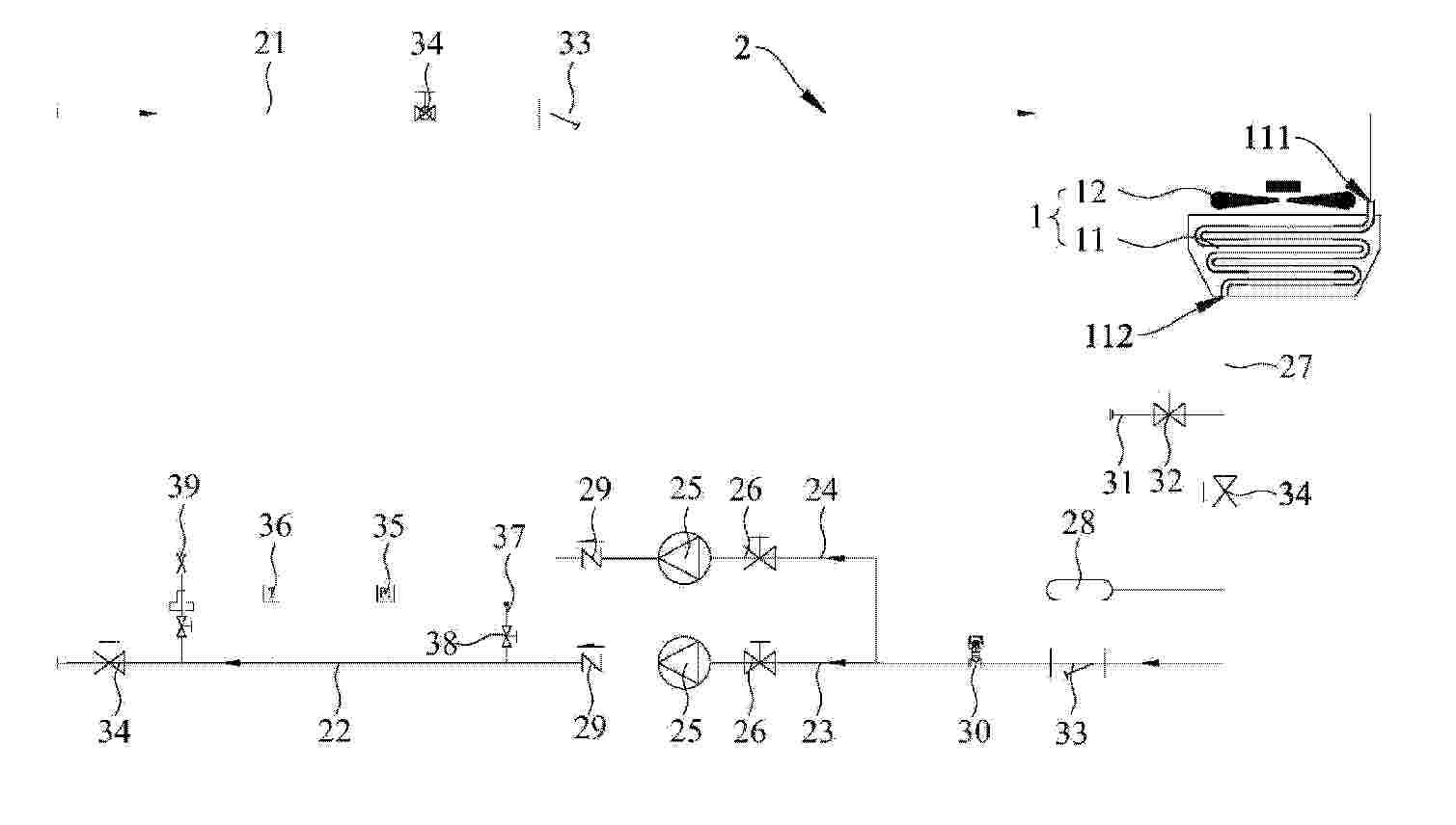
Provided in the present application is a liquid-cooling unit for a battery cluster, the liquid-cooling unit comprising a heat exchanger (11) and a pipeline system (2), wherein the heat exchanger (11) is configured to perform heat exchange on a coolant that flows therethrough; the pipeline system (2) comprises a first connection pipe (21) and a second connection pipe (22); the heat exchanger (11) is provided with a first connection port (111) and a second connection port (112); the first connection pipe (21) is connected to the first connection port (111); the second connection pipe (22) is connected to the second connection port (112) by means of a main pipe (23) and a bypass pipe (24) that are arranged in parallel; and each of the main pipe (23) and the bypass pipe (24) is provided with a pump (25) and a first valve (26).
Resumen de: WO2026046043A1
An electrode sheet, a battery cell unit, a battery, and an electric device. The electrode sheet comprises a current collector and an active material layer; the current collector comprises a conductive polymer film, and the conductive polymer film is configured to be connected to a polymer material; and the active material layer is provided on at least one surface of the current collector. The electrode sheet has good sealing reliability.
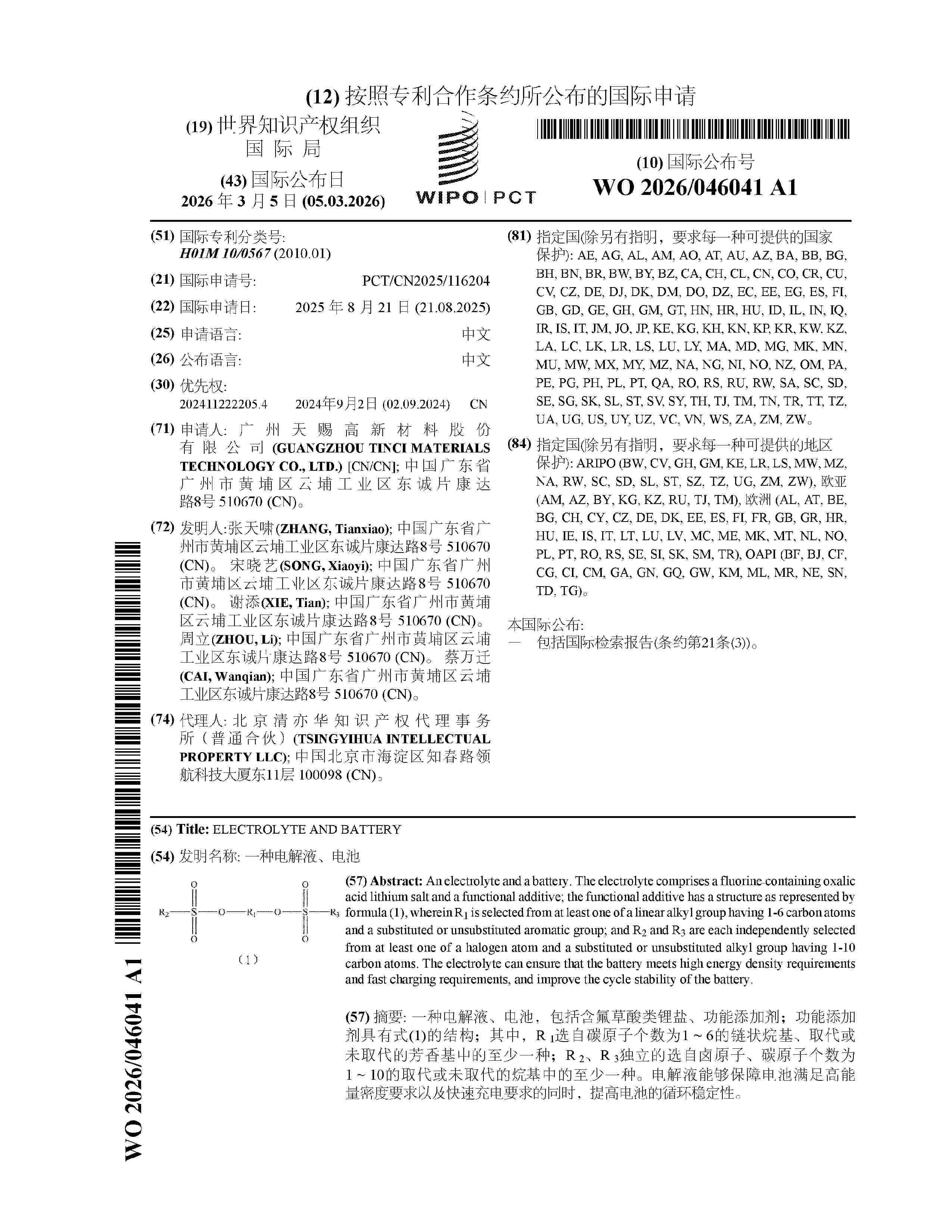
Resumen de: WO2026046041A1
An electrolyte and a battery. The electrolyte comprises a fluorine‑containing oxalic acid lithium salt and a functional additive; the functional additive has a structure as represented by formula (1), wherein R1 is selected from at least one of a linear alkyl group having 1-6 carbon atoms and a substituted or unsubstituted aromatic group; and R2 and R3 are each independently selected from at least one of a halogen atom and a substituted or unsubstituted alkyl group having 1-10 carbon atoms. The electrolyte can ensure that the battery meets high energy density requirements and fast charging requirements, and improve the cycle stability of the battery.
Resumen de: WO2026045891A1
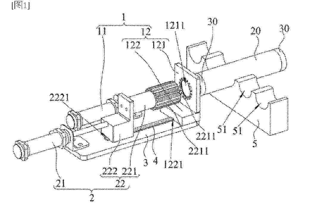
A battery cell tape-wrapping device and a battery cell tape-wrapping method. The battery cell tape-wrapping device comprises a tape folding mechanism (1) and a tape pressing mechanism (2). The tape folding mechanism (1) comprises a tape-folding driving assembly (11) and a tape folding assembly (12), wherein the tape folding assembly (12) is provided with a tape folding hole (1211); the hole wall of the tape folding hole (1211) comprises a tape folding hole wall (12111), the tape folding hole wall (12111) being inclined towards a central hole of a battery cell (20) from the side thereof close to an end face of the battery cell (20) to the side thereof away from the end face of the battery cell (20); and the tape-folding driving assembly (11) can drive the tape folding assembly (12) to move towards the end face of the battery cell (20), such that the hole wall of the tape folding hole (1211) folds an adhesive tape (30), which extends beyond the end face of the battery cell (20), towards the central hole of the battery cell (20). The tape pressing mechanism (2) comprises a tape-pressing driving assembly (21) and a tape pressing assembly (22), wherein the tape-pressing driving assembly (21) can drive the tape pressing assembly (22) to move towards the end face of the battery cell (20), such that the tape pressing assembly (22) passes through the tape folding hole (1211) to press the folded adhesive tape (30) against the end face of the battery cell (20).
Resumen de: WO2026048233A1
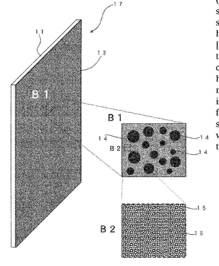
Problem Provided are: a fire-spread prevention sheet capable of achieving elastic deformation that efficiently absorbs expansion of a heat source while achieving reflection of heat from the heat source; and a battery comprising the same. Solution The present invention relates to: a fire-spread prevention sheet that is interposed between heat sources and is capable of preventing the spread of fire between the heat sources, and has a laminate structure having a plurality of layers, wherein a metal-film-equipped rubber sheet 17, in which a metal film 13 is provided on at least one surface in the thickness direction of a first rubber sheet 11, is provided inside the fire-spread prevention sheet in the thickness direction, and the metal film 13 is a film in which metal particles 15 are deposited; a method for manufacturing the fire-spread prevention sheet; and a battery.
Resumen de: WO2026048112A1
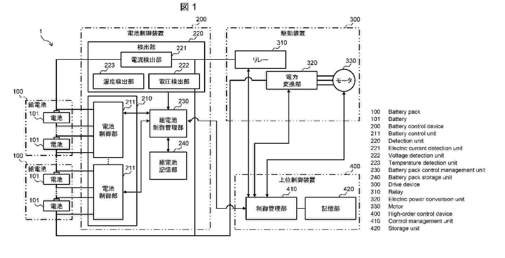
As shown in fig. 2, a battery pack control management unit 230 of a battery control device 200 of a battery 101 realizes: a service life model 2302 for deriving temporal deterioration of a service life prediction parameter that pertains to the battery and predicting the SOHQ of the battery on the basis of the temporal deterioration; an assessment unit 2306 for assessing whether it is necessary to change performance suppression of the battery so that the predicted service life of the battery falls within a required service life; and a setting unit 2308 for determining an adjustment parameter for the performance suppression of the battery on the basis of an assessment result from the assessment unit. The setting unit 2308 sets a suppression level on the basis of the difference between a predicted value of the SOHQ and a target value therefor.
Resumen de: WO2026048106A1
Provided are: a powder with which it is possible to reduce peeling at the interface of a sheet (14), and a corresponding sheet and secondary battery (10) The powder contains solid electrolyte particles (18), and the angularity of a cross-sectional contour (19) of the particles is 300-1600. The particles more preferably have a Vickers hardness of 80 HV or more. This sheet contains said powder. This secondary battery includes, in order, a positive electrode (11), an electrolyte layer (14), and a negative electrode (15). The negative electrode includes an active material layer (17) comprising lithium metal. The electrolyte layer includes said sheet.
Nº publicación: WO2026048098A1 05/03/2026
Solicitante:
VEHICLE ENERGY JAPAN INC [JP]
\u30D3\u30FC\u30AF\u30EB\u30A8\u30CA\u30B8\u30FC\u30B8\u30E3\u30D1\u30F3\u682A\u5F0F\u4F1A\u793E
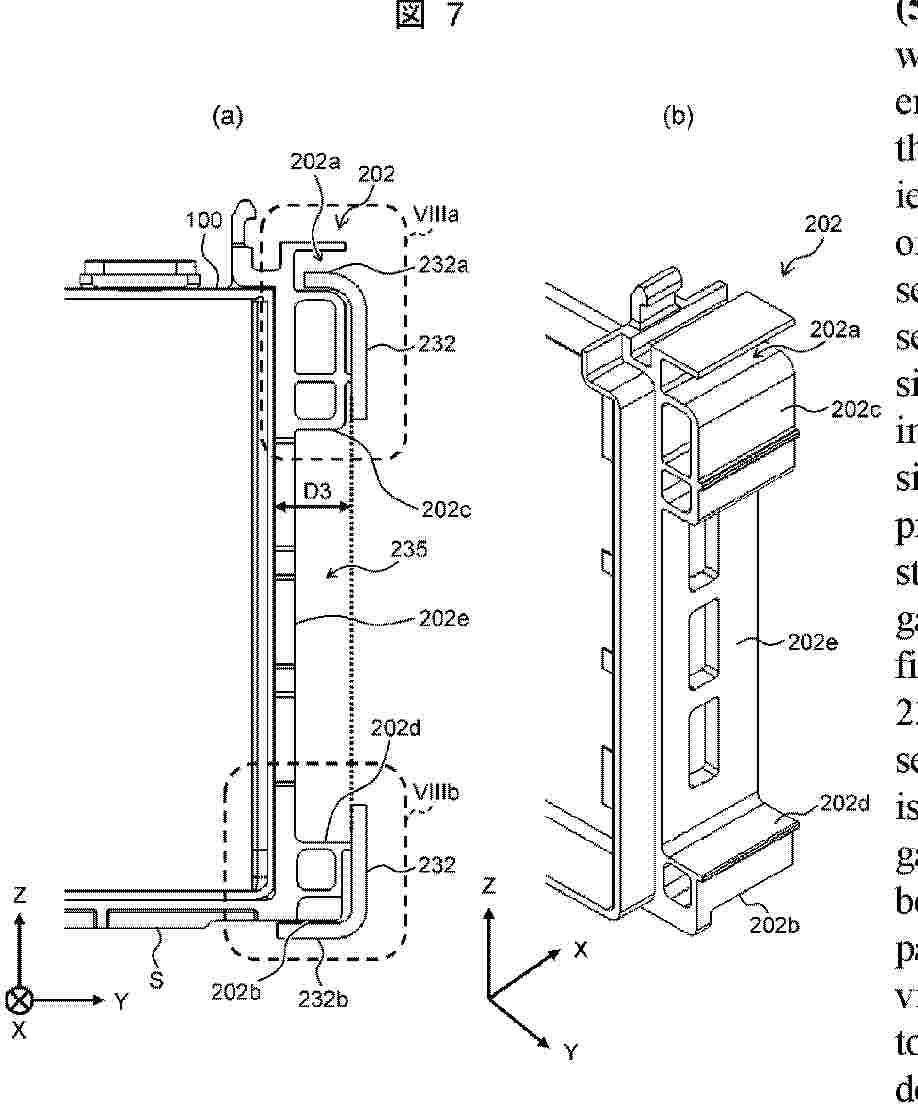
Resumen de: WO2026048098A1
A battery pack comprises: a battery group in which batteries 100 and cell spacers 202 are alternately stacked; end members arranged on the side surfaces of the battery group that are positioned at both stacking-direction ends of the batteries 100; and second side plates 232 arranged on the side surfaces of the battery group that extend along the stacking direction, the second side plates 232 engaging with the cell spacers 202. The second side plates 232 each include a first protrusion 232a positioned on the side of the battery pack distant from a mounting surface S, and a second protrusion 232b positioned on the side of the battery pack near the mounting surface S, as a set of protrusions that bend from the side surfaces extending along the stacking direction in the direction of the batteries 100 and engage with the cell spacers 202. The cell spacers 202 each have a first engagement part 202a that engages with the first protrusion 232a, and a second engagement part 202b that engages with the second protrusion 232b. The ratio of a first interval (D1) that is the interval between the first protrusion 232a and the first engagement part 202a to a second interval (D2) that is the interval between the second protrusion 232b and the second engagement part 202b is within the range of 0.5-2.0. There is thereby provided a battery pack in which, even when vibration is applied to the battery pack, the side plates are unlikely to come off, and deformation is unlikely to occur.
 BOPI
BOPI
 Sede Electrónica