Si deseas distinguir tus productos, servicios o ambos de los de otra empresa, es posible que necesites una marca o nombre comercial. Descubre qué son, en qué consiste su procedimiento de registro y qué implica.

Información sobre los plazos de presentación de solicitudes de transformación de marcas de la Unión Europea en marca nacional española. Más información


Si tienes un nuevo dispositivo, producto o procedimiento que resuelva un problema técnico o tenga una ventaja práctica, existen distintas formas de protegerlo en España y en otros países. Descubre cómo hacerlo.

¿Tu innovación reside en la estética, la ornamentación o la apariencia de tu producto? Protégela mediante un diseño industrial. Descubre qué derechos confiere el registro y cómo realizar la tramitación.

Las indicaciones geográficas protegen el nombre de un producto originario de una zona geográfica, a la cual le debe una determinada calidad, reputación u otra característica. Descubre qué son, en qué consiste su procedimiento de registro y qué beneficios conceden.

Las patentes publicadas en todo el mundo son una valiosa fuente de información científica, técnica y comercial.

Si eres emprendedor/a o una empresa y quieres potenciar y mejorar la rentabilidad de tu negocio protegiendo de forma adecuada los activos intangibles de tu organización, en este espacio encontrarás lo necesario.


 1532
resultados
1532
resultados
 Última actualización
18/03/2026 [07:26:00]
Última actualización
18/03/2026 [07:26:00]


 Resultados 975 a 1000 de 1532

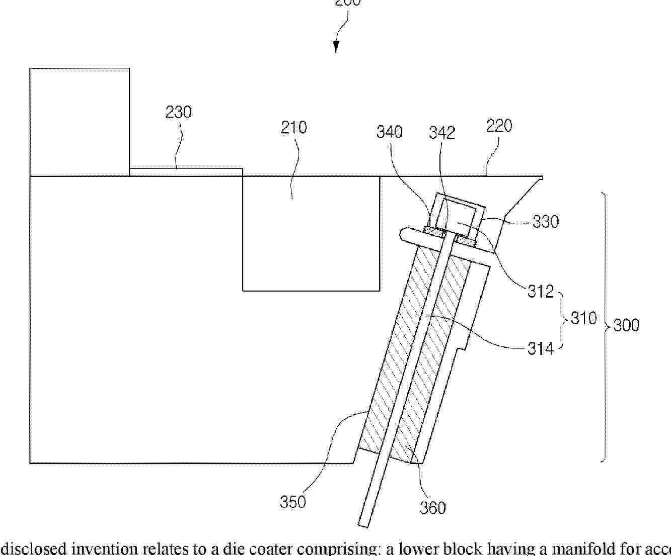
Resumen de: WO2026049431A1
The disclosed invention relates to a die coater comprising: a lower block having a manifold for accommodating slurry; and an upper block coupled to the lower block, wherein a slit is formed along a TD side on the front surfaces of the lower block and the upper block, and a land part is provided between the manifold and the slit. The die coater comprises: a slot formed along the TD side below the land part of the lower block; and a plurality of lip varying mechanisms in which a solenoid extends from the bottom surface of the lower block and passes through the slot to perform a push operation of pushing the land part and a pull operation of pulling the land part.

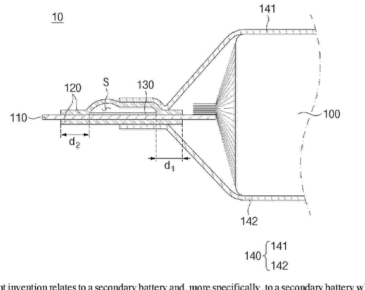
Resumen de: WO2026049414A1
The present invention relates to a secondary battery and, more specifically, to a secondary battery which can be repeatedly charged and discharged. A secondary battery according to an embodiment of the present invention comprises: an electrode assembly comprising electrodes and a separator; a housing accommodating the electrode assembly; an electrode lead connected to the electrode assembly and protruding to the outside of the housing; a lead film covering at least a part of the electrode lead such that the electrode lead is insulated from the housing; and a gas discharge guide portion provided between the electrode lead and the lead film and forming a gas discharge path through which gas inside the housing is discharged to the outside when the internal pressure of the housing increases, wherein a gap between one end of the lead film adjacent to the electrode assembly and the gas discharge guide portion may be narrower than a gap between the other end of the lead film and the gas discharge guide portion.
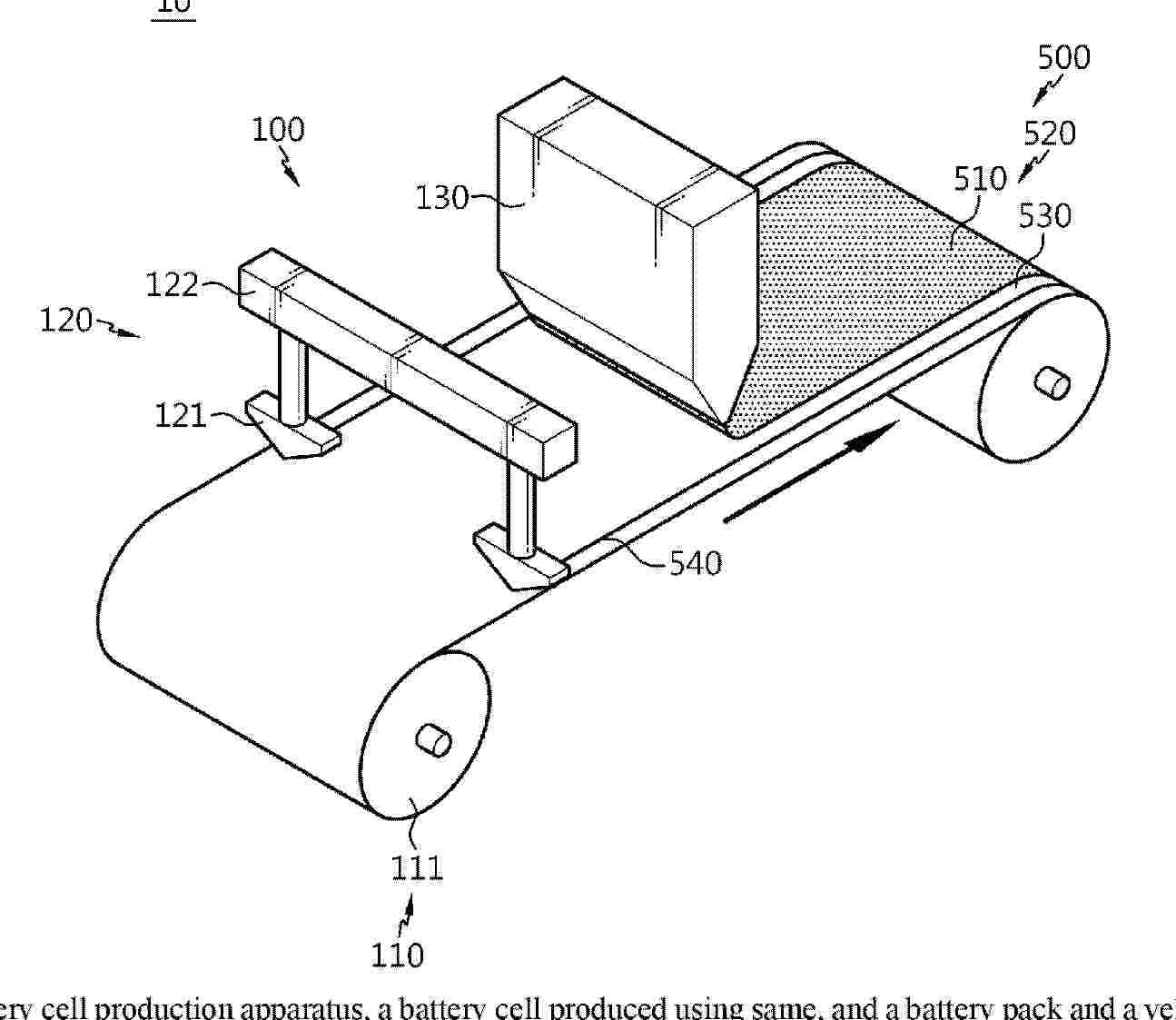
Resumen de: WO2026049403A1
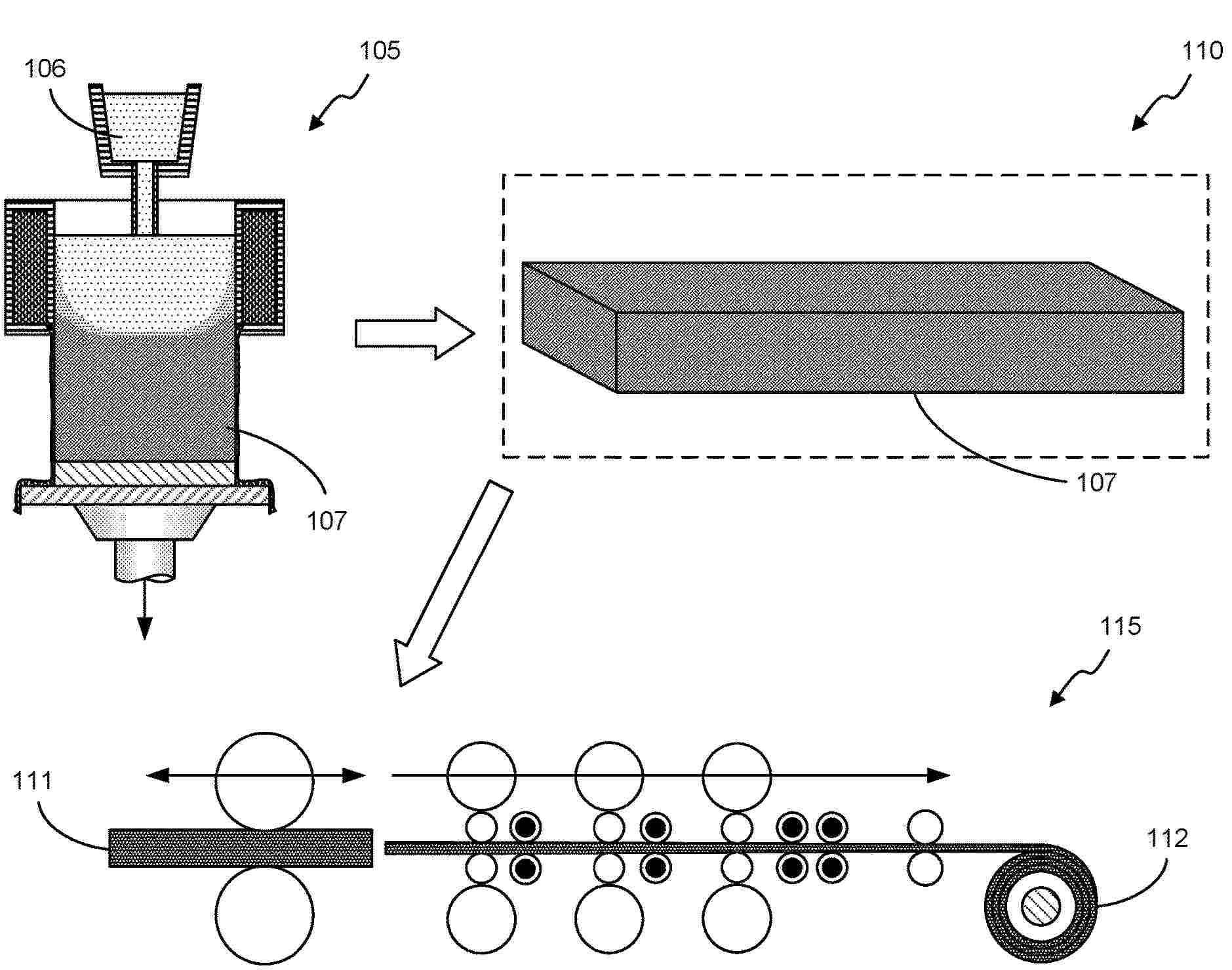
A battery cell production apparatus, a battery cell produced using same, and a battery pack and a vehicle comprising the battery cell are disclosed. The battery cell production apparatus. according to one embodiment of the present invention, which produces a battery cell by using an electrode foil on which a coating layer is formed, comprises: an electrode generation member for generating an electrode foil; a winding member for winding, in the form of a jelly roll, an electrode generated using the electrode generation member; and a folding member for folding the electrode.
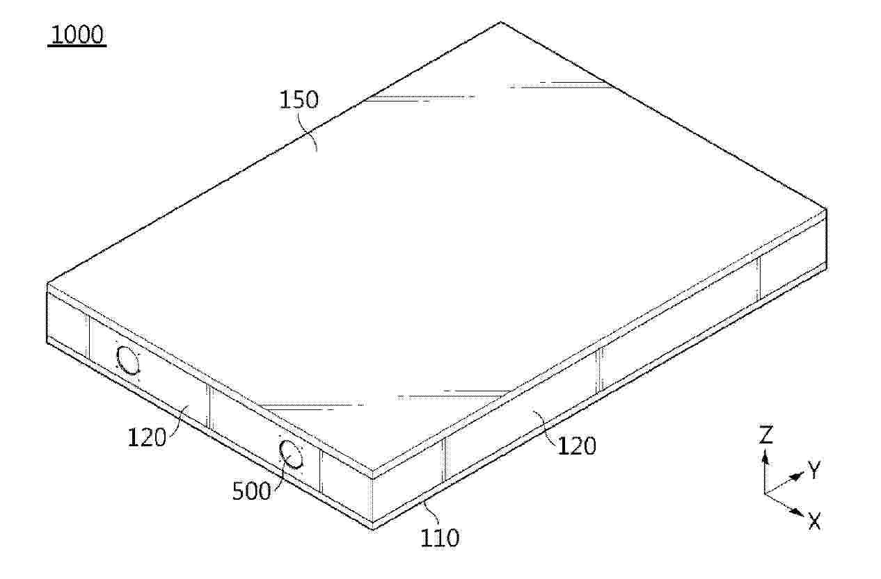
Resumen de: WO2026049402A1
A battery pack is disclosed. A battery pack according to an embodiment of the present invention may comprise: a case providing a space therein and having a pack cover; a battery stack located inside the case and having a plurality of battery cells; a top cover located between the battery stack and the pack cover; and a heat insulating cover having a top part coupled to the upper surface of the top cover and a first side part covering one side of the battery stack.
Resumen de: WO2026049488A1
The present invention provides a secondary battery module comprising a secondary battery stack having stacked therein a plurality of secondary batteries each having two long sides and two short sides connecting both ends of the long sides, respectively, the secondary battery module comprising a foam pad inserted between adjacent secondary batteries in the secondary battery stack, wherein the foam pad includes: a body made of a flexible material and having an accommodation part which is a sealed space formed therein; and a working fluid injected into the accommodation part, the deformation of the accommodation part occurs by the pressure acting on the secondary batteries and the flow of the working fluid occurs in the accommodation part.
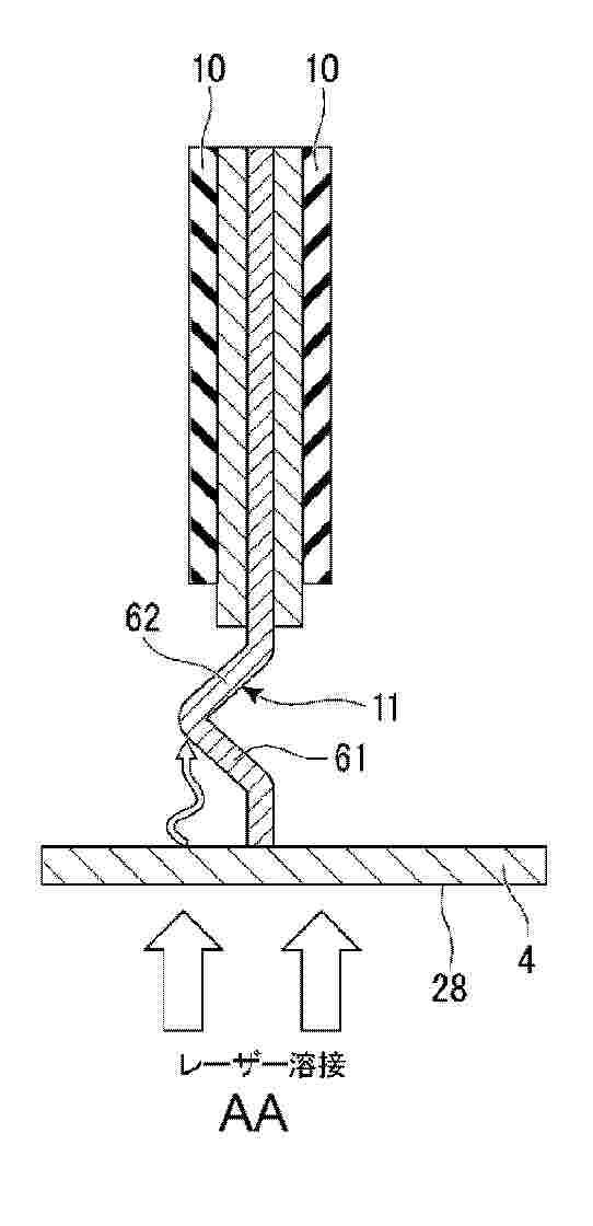
Resumen de: WO2026048688A1
This method for manufacturing a power storage device comprises: a step for alternately laminating an electrode foil and separators, and causing at least a part of an active-material uncoated portion of the laminated electrode foil to protrude from end portions of the separators in a direction along a short side of the electrode foil; a step for bending at least a part of the active-material uncoated portion at a plurality of locations to form a plurality of extension portions extending in a direction intersecting the electrode foil so as to cover the separators when viewed from the direction along the short side of the electrode foil; and a step for laser-welding the active-material uncoated portion and a current collector plate by irradiating an outer surface of the current collector plate with laser light in a state in which an inner surface of the current collector plate is in contact with a part of the active-material uncoated portion that is outside the plurality of extension portions in the direction along the short side of the electrode foil.
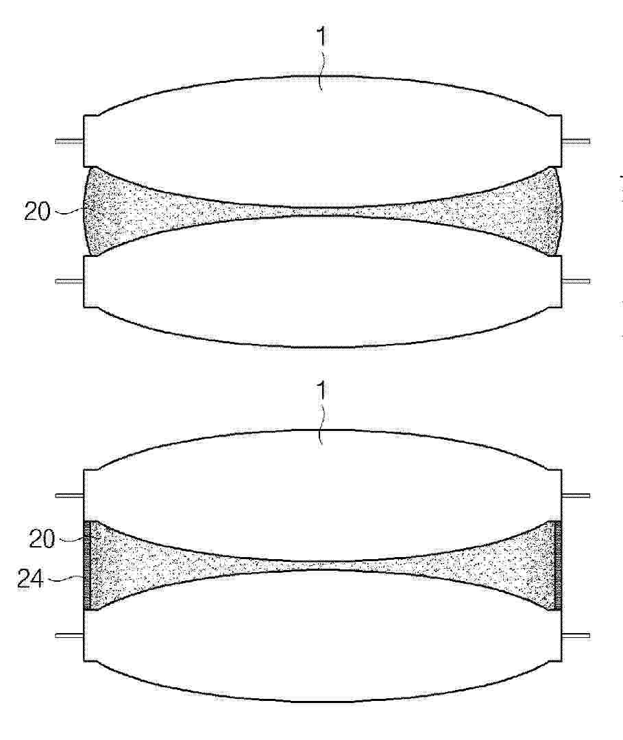
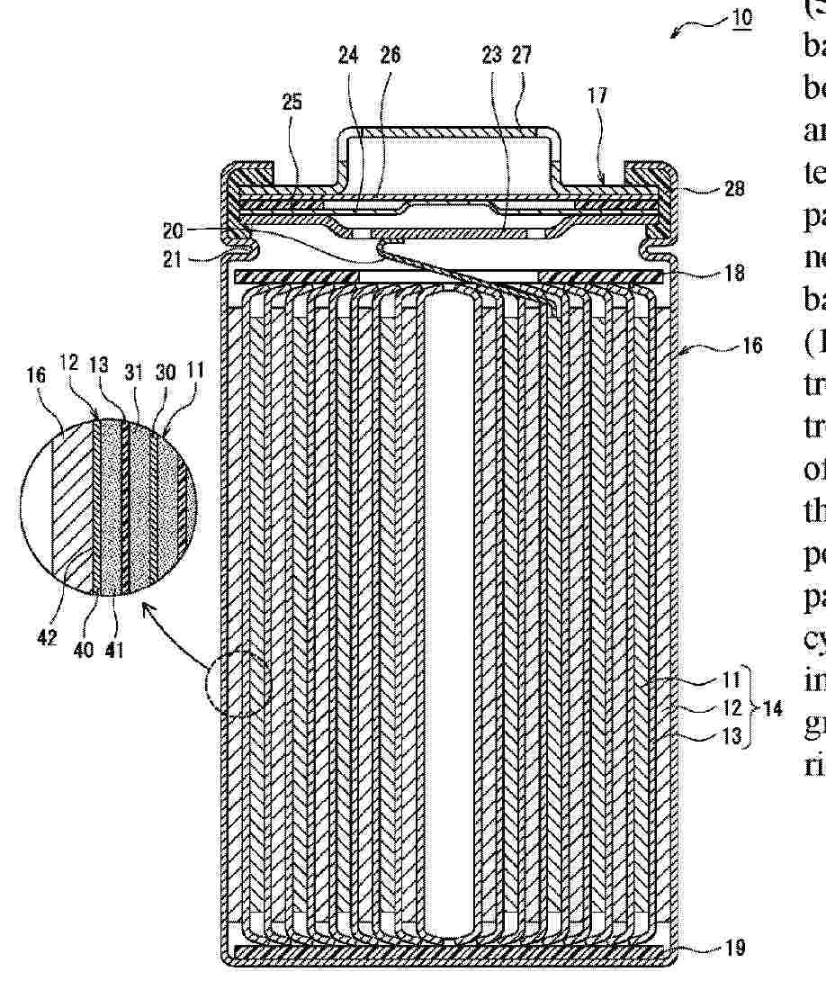
Resumen de: WO2026048547A1
Disclosed is a nonaqueous electrolyte secondary battery (10) which is characterized by comprising: an electrode body (14) that is obtained by winding a positive electrode (11) and a negative electrode (12) with a separator (13) being interposed therebetween; a nonaqueous electrolyte; and an outer package can (16) that houses the electrode body (14) and the nonaqueous electrolyte. This nonaqueous electrolyte secondary battery (10) is also characterized in that: the negative electrode (12) has a negative electrode core body (40) and a negative electrode mixture layer (41) that is provided on the negative electrode core body (40); an exposed part (42) in which the surface of the negative electrode core body (40) is exposed is formed on the outer peripheral surface of the electrode body (14); the exposed part (42) is in contact with the inner surface of the outer package can (16); the nonaqueous electrolyte contains a heterocyclic compound that comprises at least one electron-withdrawing group R and a heterocyclic ring; the electron-withdrawing group R contains oxygen and/or nitrogen; and the heterocyclic ring contains nitrogen and sulfur.
Resumen de: WO2026048595A1
This lithium secondary battery comprises: a positive electrode; a negative electrode facing the positive electrode; a separator disposed between the positive electrode and the negative electrode; and a nonaqueous electrolyte. The negative electrode has a negative electrode current collector and a negative electrode tab electrically connected to the negative electrode current collector. In the negative electrode, lithium metal is deposited on the negative electrode current collector during charging, and lithium metal is dissolved in the nonaqueous electrolyte during discharging. The negative electrode tab contains stainless steel at least in a connection portion with the negative electrode current collector.
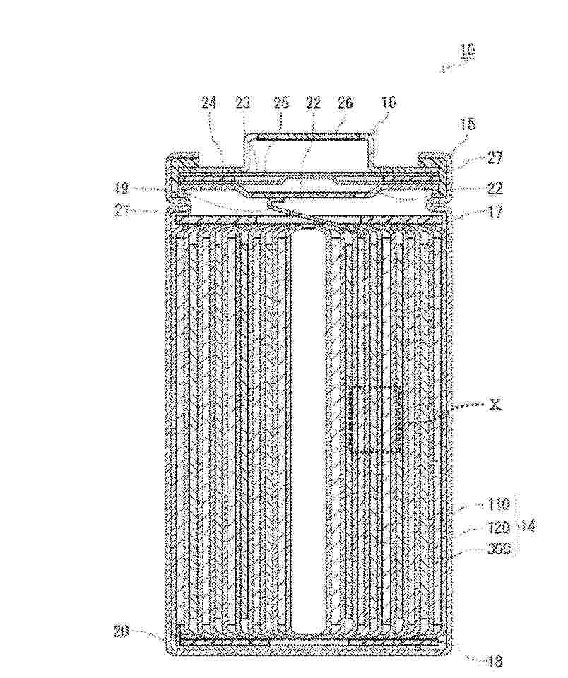
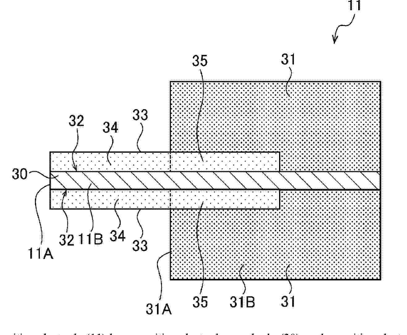
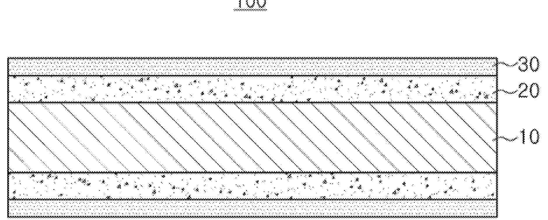
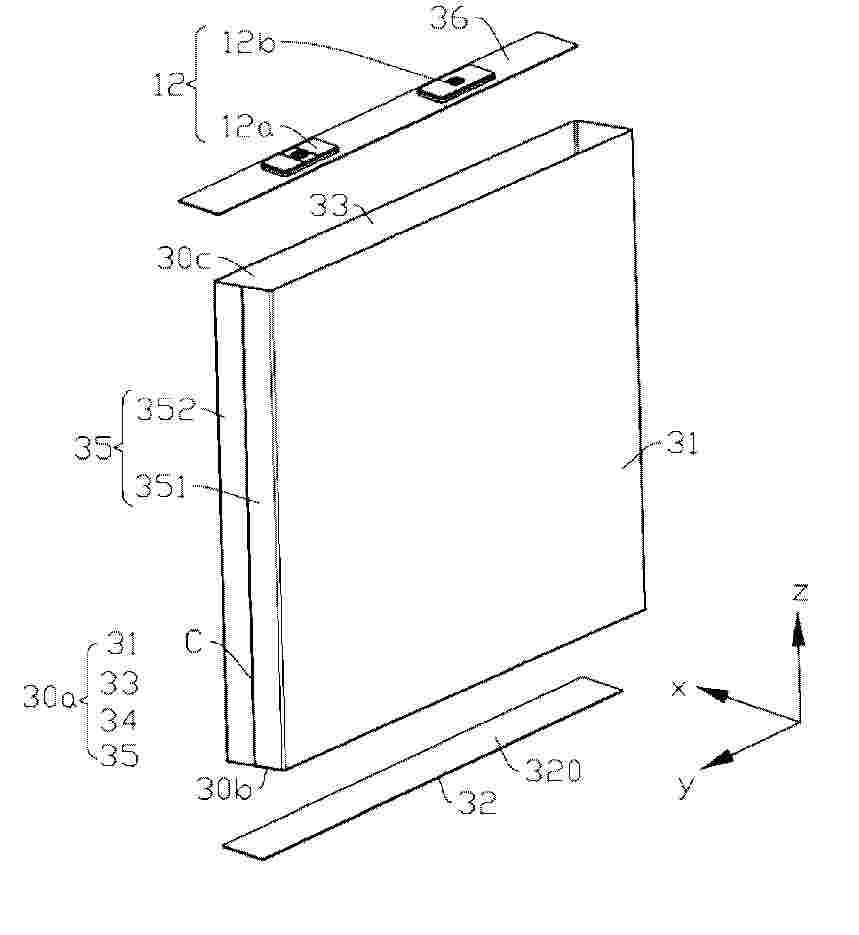
Resumen de: WO2026048546A1
A positive electrode (11) has a positive electrode core body (30), and a positive electrode mixture layer (31) and a protective layer (33) that are formed on the positive electrode core body (30). A mixture layer non-formation portion (32) at which the positive electrode mixture layer (31) is not formed is provided to a winding start end part (11B) of the positive electrode (11). The protective layer (33) contains an insulating material as the main component, and has a first region (34) that covers the mixture layer non-formation portion (32), and a second region (35) that is disposed between the positive electrode core body (30) and the positive electrode mixture layer (31). The volume resistivity of the protective layer (33) in the second region (35) is less than the volume resistivity of the protective layer (33) in the first region (34).
Resumen de: US20260066476A1
Battery array busbar frame designs are disclosed for use within traction battery packs. An exemplary battery array may include a busbar frame that includes features that facilitate the use of mechanical fastenerless connections inside the battery array. These features may include legs that can be mounted to a top cover and/or bottom cover of an array housing via an adhesive, and holders that provide an interface for connecting cell spacers to the busbar frame in order to mitigate busbar frame and/or cell spacer motion and increase the structural integrity of the battery array. Gaps between adjacent legs of the busbar frame may further establish coolant flow passages for directing a coolant around battery cells in order to thermally manage the battery array.
Resumen de: US20260066328A1
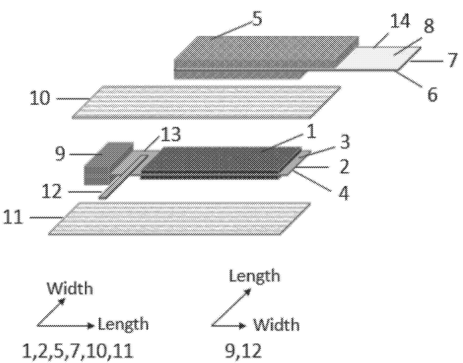
A cylindrical battery having a wound jelly roll configuration that includes an anode current collector having a first surface and an opposing second surface; at least one anode disposed on the first surface of the anode current collector; at least one Li metal film disposed on the first surface anode current collector, wherein the at least one Li metal film is spaced apart from the anode; a cathode current collector having a first surface and an opposing second surface; at least one cathode disposed on the first surface of the cathode current collector; and a first membrane separator positioned between the anode and the cathode.
Resumen de: US20260066332A1
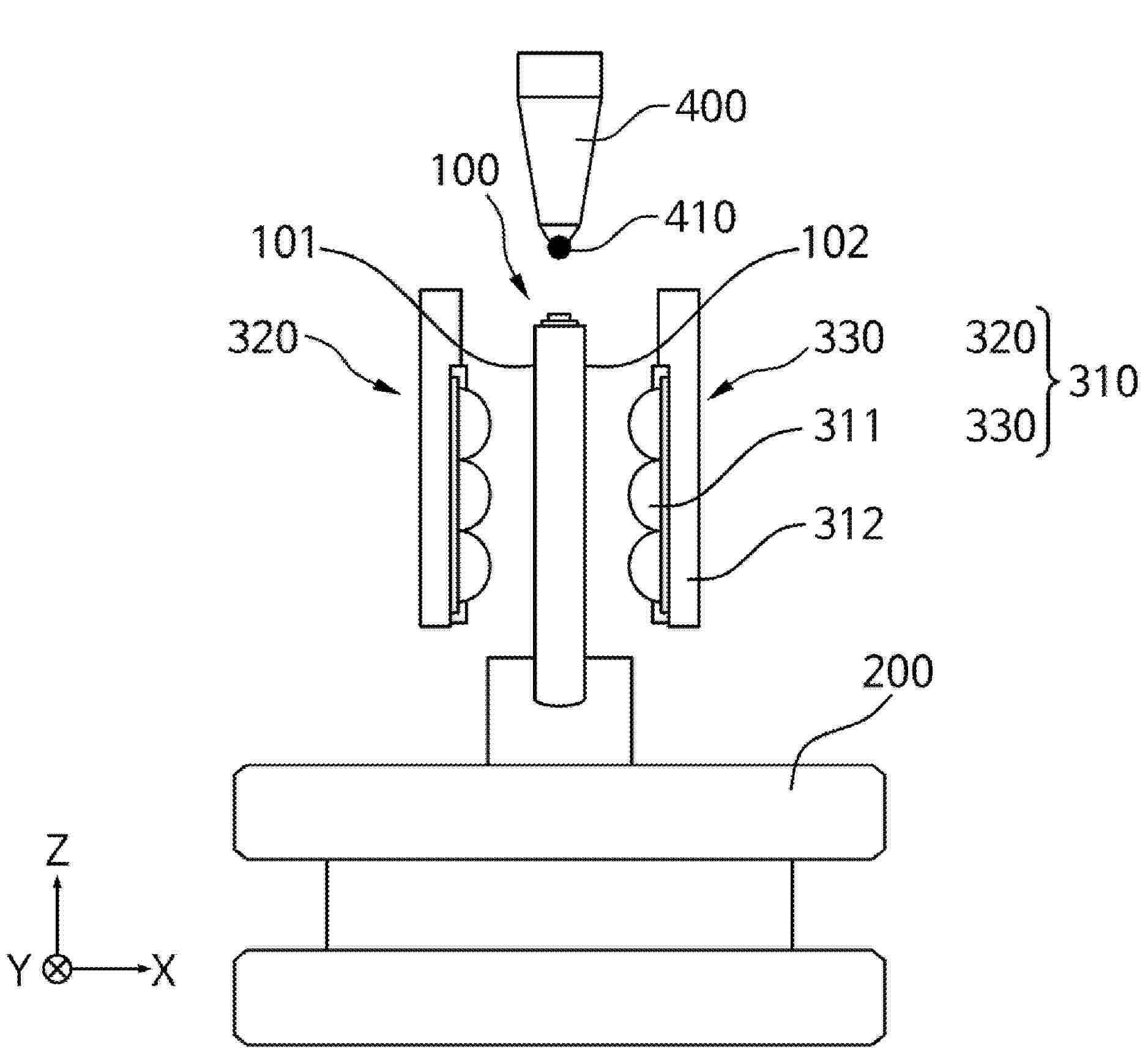
A battery cell pressurizing device includes a battery cell arranger configured to arrange a battery cell, a battery cell pressurizer above the battery cell arranger, the battery cell pressurizer being configured to pressurize the battery cell, and an electrolyte injection port sealer above the battery cell pressurizer, the electrolyte injection port sealer being configured to seal an electrolyte injection port of the battery cell while the battery cell is pressurized by the battery cell pressurizer.
Resumen de: US20260066363A1
A separator for a secondary battery includes a porous substrate, an inorganic layer including a first inorganic particle on at least one surface of the porous substrate, and an aramid resin layer including an aramid resin and a second inorganic particle on the inorganic layer, wherein an average diameter D50 of a circle-equivalent particle of the second inorganic particle is less than 0.1 μm.
Resumen de: US20260066309A1
Described are batteries and battery components including a cathode current collector comprising a 1xxx series aluminum alloy or an 8xxx series aluminum alloy. The cathode current collector can have a thickness of from 5 μm to 12 μm. In some examples, a cathode active material layer may be disposed over at least a portion of the cathode current collector. The cathode current collector may have both surfaces that are in contact with the active material layer being matte surfaces. Battery cells including the cathode current collector may retain a specific capacity above 90% of an initial specific capacity for up to 3000 cycles or more. Additionally, the battery cells including the cathode current collector may retain an energy density above 90% of an initial energy density for up to 3000 cycles or more.
Resumen de: US20260066426A1
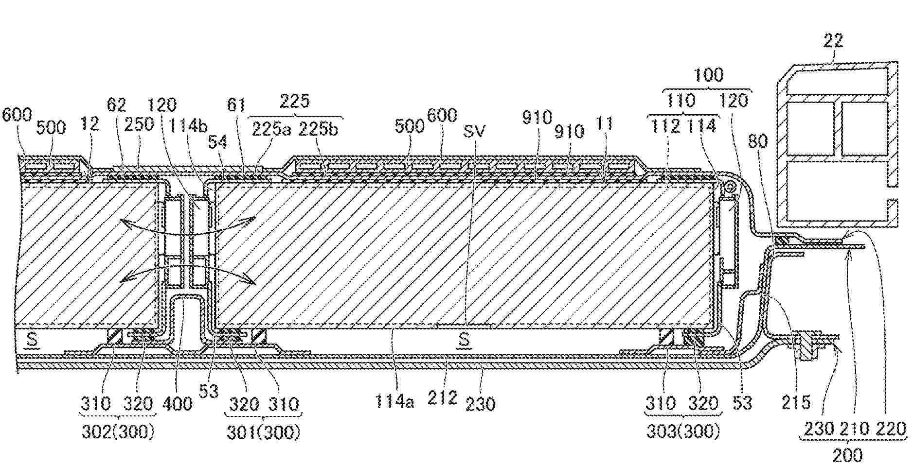
A power storage device includes a first power storage stack including a plurality of power storage cells disposed in a first direction, a second power storage stack including a plurality of power storage cells and facing the first power storage stack in a second direction, an upper wall covering the first power storage stack and the second power storage stack, and a reinforcing member provided on the upper wall. The upper wall includes a top portion located above and between the first power storage stack and the second power storage stack. The reinforcing member is provided on the top portion.
Resumen de: US20260066319A1
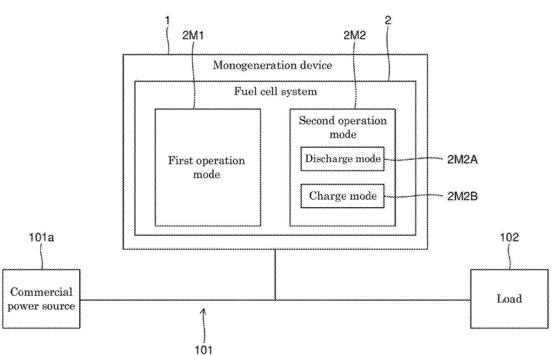
A fuel cell system includes a fuel cell, and a battery that stores power output from the fuel cell, and has a first operation mode in which power output from the fuel cell is extracted to the outside, and a second operation mode including a discharge mode in which power output from the battery is extracted to the outside. A control method for a fuel cell system includes switching between the first operation mode and the second operation mode based on target power of the fuel cell.
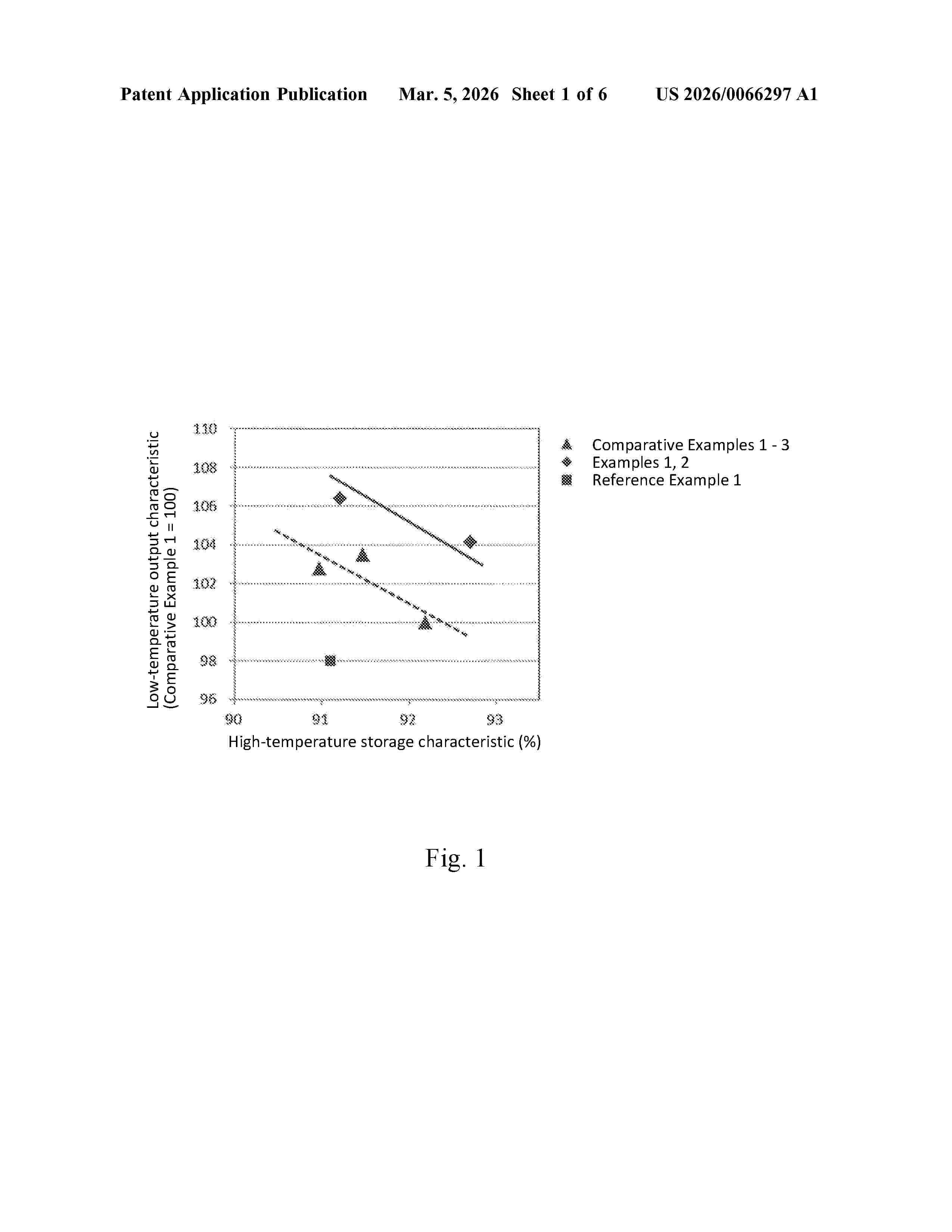
Resumen de: US20260066297A1
A negative electrode raw material may be suitable for a nonaqueous secondary battery, the negative electrode material including a graphite. The negative electrode material is configured such that, when a mercury intrusion volume and a mercury extrusion volume, determined by mercury intrusion, are defined as A and B, respectively, the value of formula (1) is 45% or higher:B/A=100(%).(1)
Resumen de: US20260066339A1
A solid electrolyte material configured to suppress a decrease in ion conductivity, the solid electrolyte material comprising a polymer electrolyte, an inorganic filler and succinonitrile, the polymer electrolyte comprises an anionic polymer.
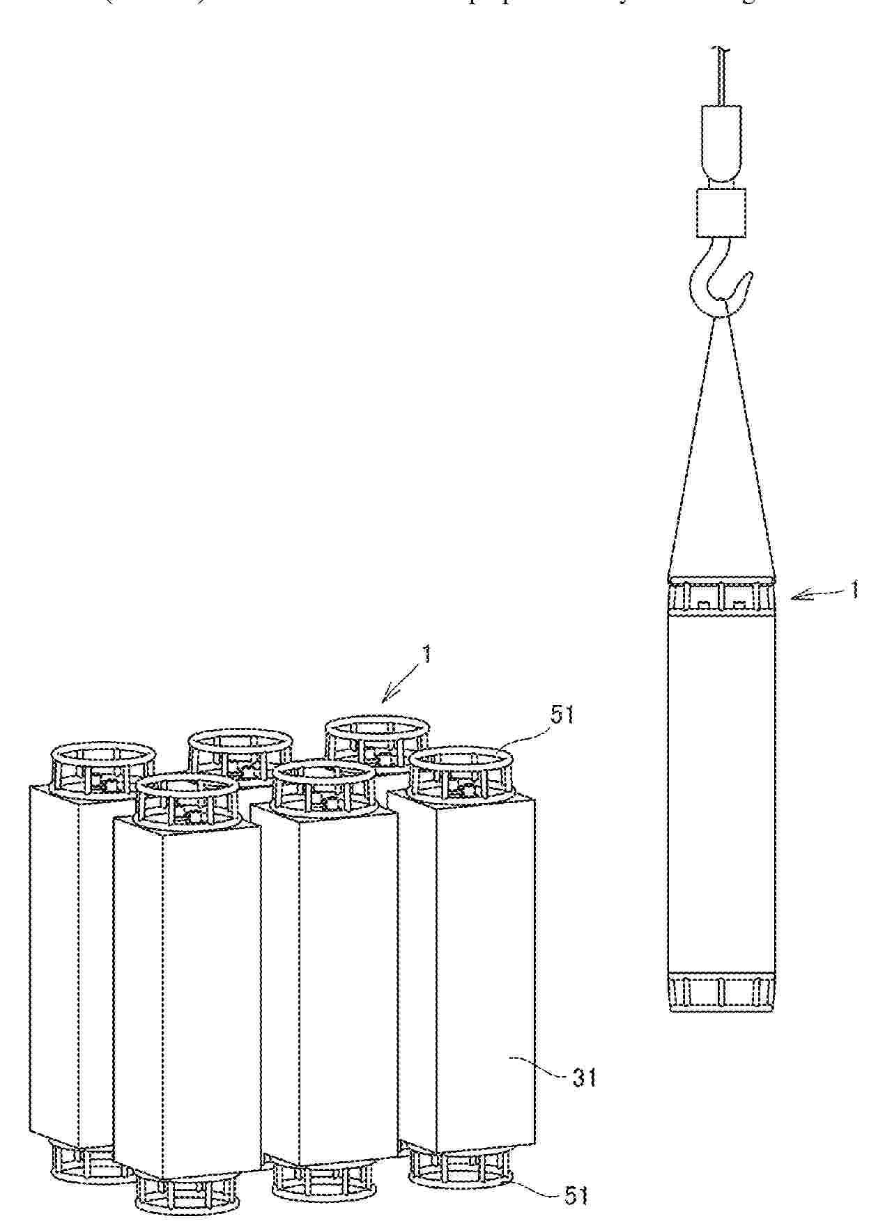
Resumen de: US20260066429A1
A battery pack including: a battery unit; a casing housing the battery unit and having a columnar shape; an external connection terminal exposed at an outer surface of the casing; and a support structure fixed to the casing. The support structure includes projects outward in a longitudinal direction of the casing from at least one end surface of the casing in the longitudinal direction, and includes a ring portion located at least one end of the battery pack in a longitudinal direction of the battery pack and oriented perpendicularly to the longitudinal direction of the casing.
Resumen de: US20260066435A1
An electricity storage apparatus according to the present disclosure includes a plurality of battery modules and a rack that accommodates the battery modules. The rack has a plurality of support plates that supports the battery modules. A bottom surface of each of the battery modules and a main surface of each of the support plates are fastened to each other. Each of the support plates is joined, via a bracket fastened on the main surface of the support plate, to another of the support plates. With such configuration, the electricity storage apparatus according to the present disclosure enables the accommodated battery modules to be sufficiently fixed even when a storage battery vibrates due to earthquake, transportation, and the like. As a result, the electricity storage apparatus according to the present disclosure enables the quake resistance to be improved.
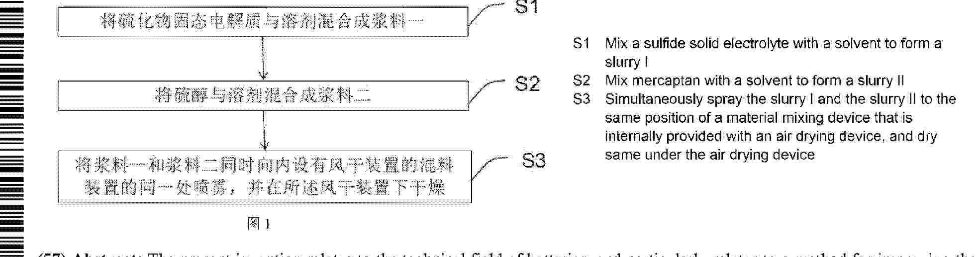
Resumen de: WO2026045392A1
The present invention relates to the technical field of batteries, and particularly relates to a method for improving the air stability of a sulfide solid electrolyte. The method comprises the following steps: mixing a sulfide solid electrolyte with a solvent to form a slurry I; mixing mercaptan with a solvent to form a slurry II; and simultaneously spraying the slurry I and the slurry II to the center of a material mixing device that is provided with an air drying device, and drying same under the air drying device, so as to complete the improvement of the air stability of the sulfide solid electrolyte. By spraying the sulfide solid electrolyte and the mercaptan, the two collide with each other at a certain airflow rate; therefore, sulfydryl of the mercaptan is coordinated with metal cations or exposed sulfur vacancies on the surface of the sulfide solid electrolyte to form a stable thiolate or complex, thereby achieving a particle coating or semi-coating effect on the sulfide solid electrolyte.
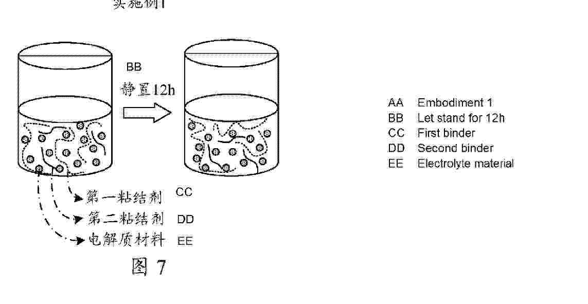
Resumen de: WO2026045368A1
Provided are a secondary battery, an electric device, a solid electrolyte layer and a preparation method therefor. The secondary battery comprises a positive electrode sheet, a negative electrode sheet, and a solid electrolyte layer located between the positive electrode sheet and the negative electrode sheet. The solid electrolyte layer comprises an electrolyte material, a first binder, and a second binder. The first binder includes a polydiene-based binder, and the second binder includes a cellulose-based binder.
Resumen de: WO2026045352A1
The present application relates to the technical field of batteries, and provides a fixture, a battery production device, an electrode assembly, a shaping method therefor, and a battery. The fixture comprises a first clamping plate, a second clamping plate, and a packaging film. The second clamping plate and the first clamping plate are stacked. The side surface of the first clamping plate facing the second clamping plate is provided with a placement recess; the side surface of the second clamping plate facing the first clamping plate is provided with a mounting recess; the placement recess is configured to place the electrode assembly; and at least part of the first clamping plate is located in the mounting recess. The packaging film covers the first clamping plate and the second clamping plate. During isostatic pressing, the mounting recess limits the first clamping plate, restricting relative movement between the first clamping plate and the second clamping plate, and the placement recess limits the electrode assembly, restricting relative movement between the electrode assembly and the first clamping plate, thereby improving the stability of the fixture and the electrode assembly during the isostatic pressing, and thus enhancing the densification effect on the electrode assembly.
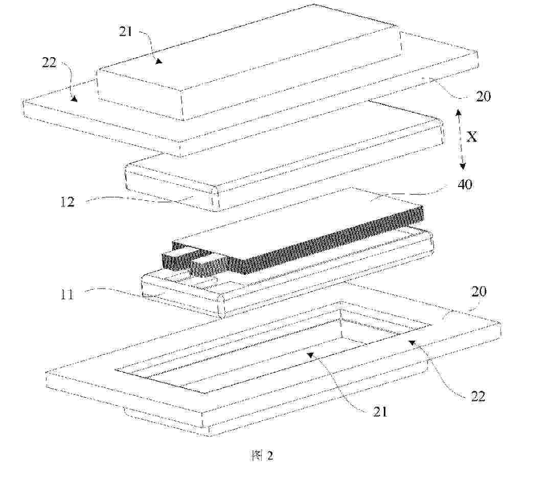
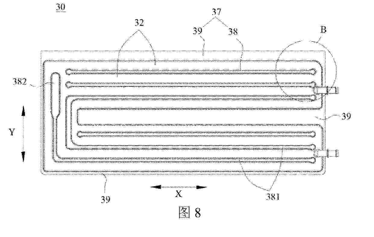
Resumen de: WO2026044462A1
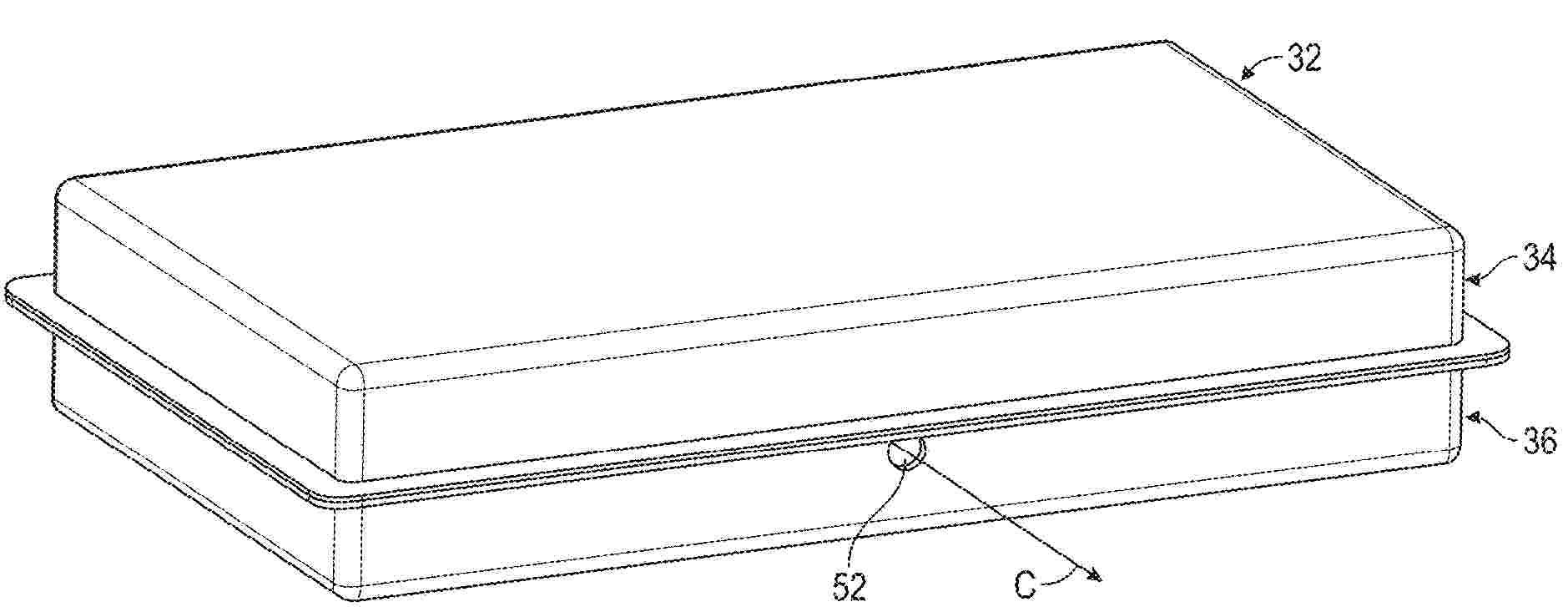
A heat exchange assembly (30), a battery apparatus (100), an electric device, and an energy storage device. The battery apparatus (100) comprises a case assembly (20), a battery cell assembly (10), and a heat exchange assembly (30). The battery cell assembly (10) is arranged in the case assembly (20). The heat exchange assembly (30) is arranged in the case assembly (20). The heat exchange assembly (30) comprises at least two flexible members (31), and the at least two flexible members (31) are stacked. The at least two flexible members (31) form a heat-sealed region (34) and a flow channel region (32) by means of hot pressing. The flow channel region (32) is used for conducting a heat exchange medium so as to perform heat exchange on the battery cell assembly (10). The heat-sealed region (34) comprises a non-heat-sealed region (37), and the at least two flexible members (31) are connected to each other in the heat-sealed region (34).
Nº publicación: WO2026044456A1 05/03/2026
Solicitante:
CONTEMPORARY AMPEREX TECHNOLOGY CO LTD [CN]
\u5B81\u5FB7\u65F6\u4EE3\u65B0\u80FD\u6E90\u79D1\u6280\u80A1\u4EFD\u6709\u9650\u516C\u53F8
Resumen de: WO2026044456A1
Disclosed in the present application are a battery cell, a battery device and an electric device. The battery cell comprises a casing, an electrode assembly, and electrode terminals, wherein an accommodating cavity is formed inside the casing, and the casing comprises a first wall, a second wall and a third wall. In a first direction, the first wall and the third wall are arranged opposite each other, the second wall is located between the first wall and the third wall, and the second wall connects the first wall and the third wall. The electrode assembly is arranged in the accommodating cavity. The electrode terminals are arranged on the casing and are electrically connected to the electrode assembly, and the electrode terminals are located on a wall portion of the casing other than the first wall, the second wall and the third wall. The face of the first wall facing the interior of the accommodating cavity is defined as a first face, the face of the second wall facing the interior of the accommodating cavity is defined as a second face, the first face is directly connected to the second face, and the connection region forms a first preset included angle, which is not less than 85° and not greater than 95°. The technical solution provided in the present application can effectively improve the reliability of the battery device.
 BOPI
BOPI
 Sede Electrónica