Si deseas distinguir tus productos, servicios o ambos de los de otra empresa, es posible que necesites una marca o nombre comercial. Descubre qué son, en qué consiste su procedimiento de registro y qué implica.

Información sobre los plazos de presentación de solicitudes de transformación de marcas de la Unión Europea en marca nacional española. Más información


Si tienes un nuevo dispositivo, producto o procedimiento que resuelva un problema técnico o tenga una ventaja práctica, existen distintas formas de protegerlo en España y en otros países. Descubre cómo hacerlo.

¿Tu innovación reside en la estética, la ornamentación o la apariencia de tu producto? Protégela mediante un diseño industrial. Descubre qué derechos confiere el registro y cómo realizar la tramitación.

Las indicaciones geográficas protegen el nombre de un producto originario de una zona geográfica, a la cual le debe una determinada calidad, reputación u otra característica. Descubre qué son, en qué consiste su procedimiento de registro y qué beneficios conceden.

Las patentes publicadas en todo el mundo son una valiosa fuente de información científica, técnica y comercial.

Si eres emprendedor/a o una empresa y quieres potenciar y mejorar la rentabilidad de tu negocio protegiendo de forma adecuada los activos intangibles de tu organización, en este espacio encontrarás lo necesario.


 1083
resultados
1083
resultados
 Última actualización
21/03/2026 [07:23:00]
Última actualización
21/03/2026 [07:23:00]


 Resultados 575 a 600 de 1083

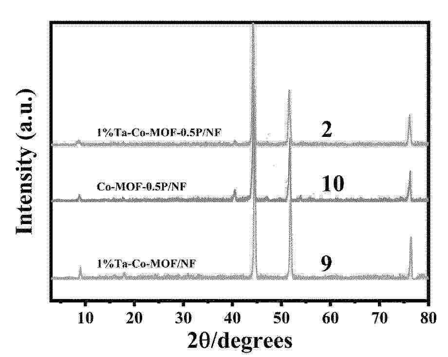
Resumen de: CN121472928A
本发明属于电催化水分解技术领域,涉及一种内建电场与不对称桥氧键共同作用的Ta‑Co‑MOF‑P/NF复合材料的制备方法与应用。所述方法首先在泡沫镍载体上通过一步溶剂热合成双金属Ta‑Co‑MOF/NF前驱体,随后通过低温磷化处理在基底上构建Co‑MOF与CoP异质界面。得益于调控磷化程度构成的内建电场及适当Ta掺杂量形成的Co‑O‑Ta不对称桥氧键,共同改变了水分子构型以提高其水分解的活性。该催化剂能够增强与水分子间的相互作用力且自由水在表面水分子构型中所占比例提升,使活性氢物种更容易解离和释放,从而加快碱性HER反应动力学和传质过程。所述材料在碱性环境中表现出优异的HER催化活性和长期稳定性。

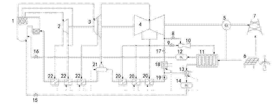
Resumen de: CN121472892A
本发明属于火电乏汽利用技术领域,具体公开了一种耦合氢储能的火电乏汽制氢系统及方法,系统包括:火力发电单元、乏汽制氢单元和风光发电单元;火力发电单元的低压缸乏汽支路出口通过乏汽流量控制阀与增汽机的低压气入口连接,低压缸抽汽出口通过抽汽流量控制阀与增汽机的高压气入口连接,增汽机的气体出口与PEM电解池的原料入口连接;PEM电解池的供电端口与火力发电单元的发电机输出端以及风光发电单元分别连接;火力发电单元的低压缸乏汽进入PEM电解池作为电解原料,火力发电单元产生的部分电能和/或者部分风光电能进入PEM电解池作为电解能量,将电能、乏汽的化学能转化为氢气的化学能并储存,满足火电机组深度调峰的需求。
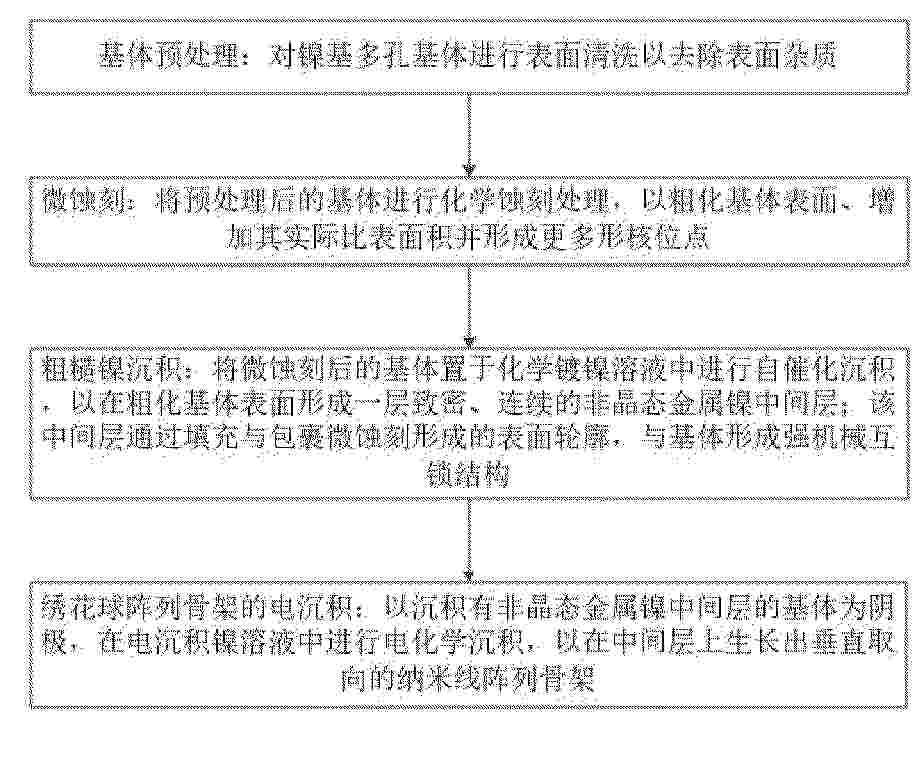
Resumen de: CN121472941A
本发明公开了一种应用于一体化电极材料的基体前处理工艺,属于电极材料制备技术领域。该工艺依次包括基体预处理、微蚀刻、粗糙镍沉积及绣花球阵列骨架电沉积,通过微蚀刻在镍基多孔基体表面构建微米级粗糙结构以提供更多形核位点;基于粗糙镍沉积在基体粗糙表面形成一层致密、非晶态的金属镍过渡层,实现与基体的强机械互锁,并兼备高耐蚀性与高导电性;最后利用电沉积在金属镍过渡层上生长出垂直取向的纳米线阵列骨架。本发明通过微蚀刻、粗糙镍沉积与电沉积三者协同作用,最终构建出从宏观基体到微观活性骨架的完整、稳定且高效的三维导电载体,从根本上提升了一体化电极材料与基体之间的结合力以及界面稳定性和传质能力。
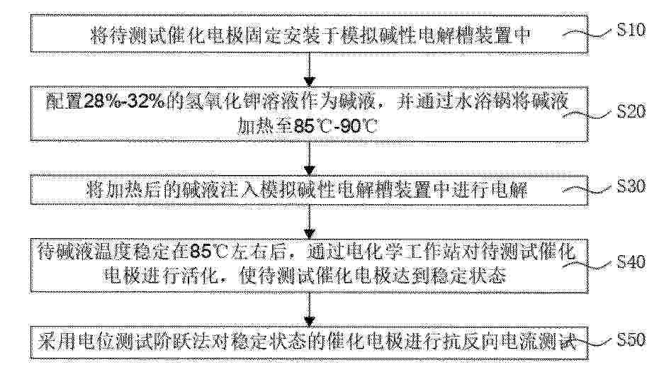
Resumen de: CN121472932A
本发明公开了一种基于模拟工业碱性电解水的催化电极抗反向电流的测试方法,包括以下步骤:S10,将待测试催化电极固定安装于模拟碱性电解槽装置中;S20,配置28%‑32%的氢氧化钾溶液作为碱液,并通过水浴锅将碱液加热至85℃‑90℃;S30,将加热后的碱液注入模拟碱性电解槽装置中进行电解;S40,待碱液温度稳定在85℃左右后,通过电化学工作站对待测试催化电极进行活化,使待测试催化电极达到稳定状态;S50,采用电位测试阶跃法对稳定状态的催化电极进行抗反向电流测试。本发明的有益效果:能够模拟实际电解环境中的反向电流现象并测试催化电极的耐反向电流性能,以优化电解水制氢系统的稳定性和工作效率。
Resumen de: CN121472907A
本发明提供一种一体化析氧反应电极及其规模化制备方法和制备系统。该规模化制备方法包括以下步骤:提供导电基底;将导电基底置于循环流动状态的腐蚀液中,同时向腐蚀液中通入含氧气体,进行自发的电化学腐蚀,使得导电基底上原位形成层状双金属氢氧化物层。本发明借助腐蚀液的循环流动与含氧气体主动供给的协同策略,实现了高性能一体化析氧反应电极的高效、均匀、可控的规模化制备,其中循环流动消除了传质限制与浓度梯度,含氧气体为自发式电化学腐蚀提供了持续稳定的反应驱动力。该协同策略在宏观上保障了电极规模化制备的一致性,在微观上调控了活性组分,避免了剧烈扰动对局部高pH生长界面的破坏,为其放大至工业化生产规模奠定了基础。
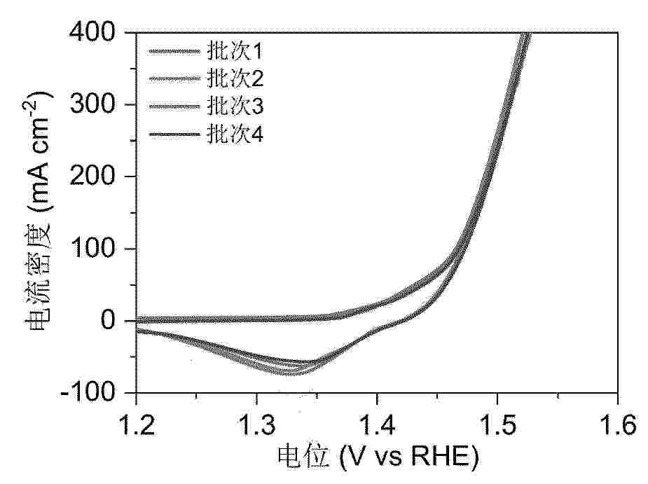
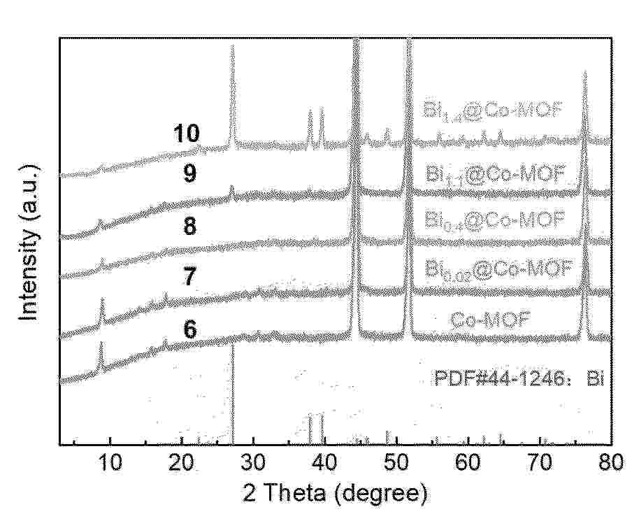
Resumen de: CN121472919A
本发明属于电催化水分解技术领域,涉及一种自支撑Biy@CoOOH/NF复合材料及其制备方法与应用。本发明通过在泡沫镍载体上通过溶剂热法合成超薄Bix@Co‑MOF/NF前驱体;随后通过电化学处理诱导前驱体发生表面重构,将其转化为CoOOH载体并同步调控其中的氧空位浓度;获得自支撑Biy@CoOOH复合材料。本发明获得的复合材料呈现高活性比表面积,可实现铋物种尺寸的精确控制,进而实现对催化性能的连续调控。且表现出优异的析氧反应催化活性与长期稳定性,适用于高效电解水制氢系统。本发明避免了使用粘结剂所带来的性能衰减问题,为高性能自支撑电极的可控制备提供了普适、可靠的技术路线。
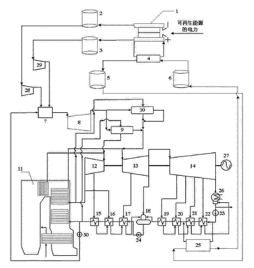
Resumen de: CN121473928A
本发明涉及一种集成电解池、氢燃机和燃煤电站的联合发电系统及方法,系统包括电解系统、氢燃气轮机发电系统和燃煤发电系统,电解系统包括质子交换膜电解池,质子交换膜电解池的电极与可再生能源发电系统电连接并利用可再生能源发电系统的电力电解水制氢,氢燃气轮机发电系统包括相互连接的燃烧室和氢燃气轮机,燃烧室与电解系统连接并通过电解产生的氢气燃烧产生蒸汽驱动氢燃气轮机发电;汽轮机组与氢燃气轮机发电系统连接,燃煤发电系统在升负荷时利用氢燃气轮机发电系统输出的蒸汽补充至汽轮机组。本发明在解决可再生能源发电电力消纳问题的基础上,协助燃煤机组升负荷,提高可再生能源的利用率,提升燃煤机组调峰的灵活性。
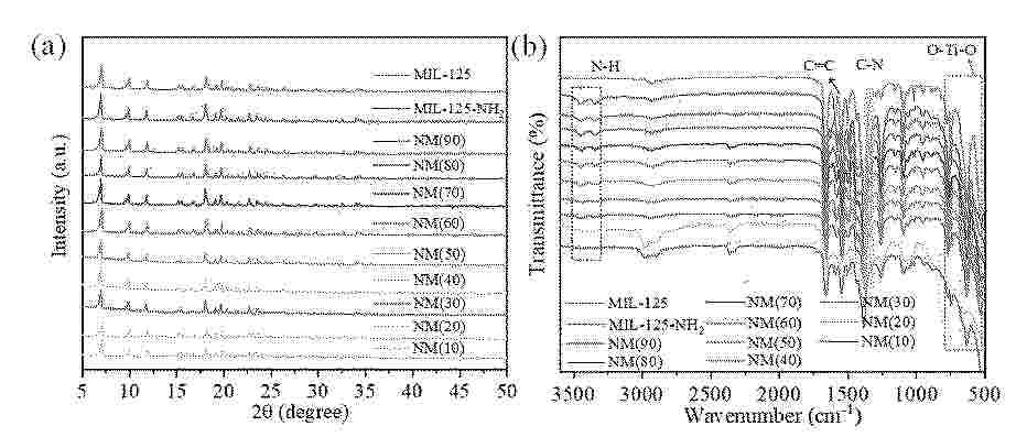
Resumen de: CN121471533A
本发明提出一种氨基基团修饰Ti基MOFs的制备方法与应用,其步骤为:将钛酸四丁酯添加到混合有机溶剂中,经搅拌和超声处理,得到混合溶剂;有机配体NH2‑BDC置于混合溶剂中得到配体Ⅰ,有机配体BDC置于混合溶剂中得到配体Ⅱ;将配体Ⅰ和配体Ⅱ分别进行搅拌和超声处理,至有机配体充分溶于混合溶液中,完成前置处理;配体Ⅰ与配体Ⅱ混合以n(NH2‑BDC)/n(BDC)计,n(NH2‑BDC)/n(BDC)为2~9:1~8,制备成NM(x)光催化剂。本发明解决现有方法制备的钛基MOFs存在配体分布不均、合成效率低,以及可见光利用率不足的问题。
Resumen de: CN121472923A
本发明公开了一种海绵状V2O5复合Fe插层石墨氮N‑V2O5@FeC及其制备方法与应用,通过球磨实现FeCl3/KCl与石墨粉的均匀混合,在250 ℃下热熔实现Fe插层石墨,从而得到高导电性的Fe插层石墨FeC。之后,在Fe插层石墨FeC中引入NH4VO3和三聚氰胺进行二次球磨,经两段式热处理成功制备出海绵状V2O5复合Fe插层石墨氮材料。本发明海绵状多孔结构大幅增加活性位点暴露,同时Fe插层诱导的石墨边缘缺陷和Fe‑O‑V键共同提升了V2O5复合材料的活性位点密度,从而增强了催化剂活性。其次,氮掺杂碳网络改善了电子传输性能,促使催化剂的电荷转移电阻降低至19.9 Ω。此外,Fe‑O‑V稳定结构和V‑O‑C键化学锚定的双重稳定机制,使材料在碱性条件下表现出良好的结构稳定性,并在OER中展现出优越的电化学性能。
Resumen de: CN121472888A
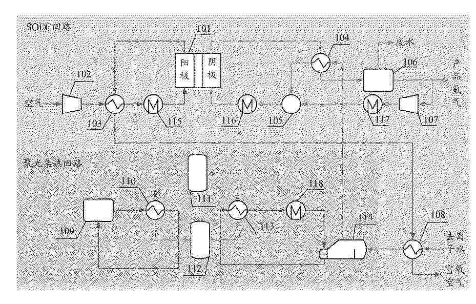
本申请提供一种制氢装置及制氢方法,涉及电解水制氢技术领域。其中,该装置中的空气压缩机、阳极换热器、SOEC电堆的阳极构成阳极回路,SOEC电堆的阴极、阴极换热器、混合器、分离器、氢气循环器构成阴极回路;气水换热器与蒸汽发生器和阳极换热器连接;聚光集热回路包括:聚光塔、一级换热器、热储罐、冷储罐、二级换热器、蒸汽发生器。该装置通过内部间接热耦合的聚光集热系统为SOEC回路供热,同时SOEC回路具有可进行深度余热回收的双回路,实现了把太阳辐照的短时波动与蒸汽生成彻底解耦,确保进入SOEC回路的蒸汽在温度与流量上均保持平稳;同时保留SOEC回路进行过热与微调的自由度,从而降低了固体氧化物电解池制氢过程中的控制难度,提高了设备稳定性。
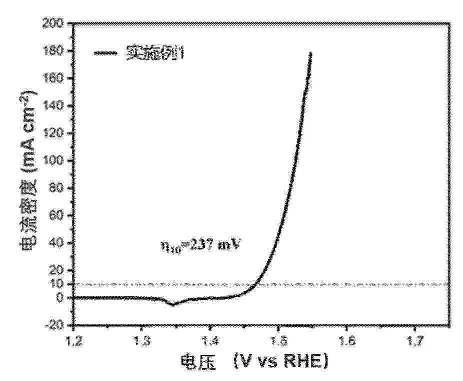
Resumen de: CN121472917A
本发明提供了一种电解水制氢催化剂及其制备方法和应用。该催化剂包含式(1)所示的铱钌复合氧化物,RuxIr(1‑x)O2 (1),x=0.1~0.9。该催化剂在酸性电解液中表现出高的活性和长期稳定性,电流密度为10mA cm‑2时的过电位不超过220mV。
Resumen de: CN121472900A
本发明提供一种电解水制氢装置的极距优化型极框结构,第一极板和第二极板相对的表面上,在电极叠层区的侧边设置有凸起;所述凸起的上侧设有第一凹槽,所述凸起的下侧形成电极安装槽;所述第一极板和第二极板的凸起相对设置,相邻的凸起上侧与所述第一极板和第二极板共同围合形成密封垫圈安装空间;第一密封垫圈安装于所述密封垫圈安装空间内;所述第一阴极和第一阳极分别安装在所述第一极板和第二极板的电极安装槽中;所述第一隔膜设置在所述第一阴极和第一阳极之间,并延伸至所述第一凹槽与第一密封垫圈之间的位置。本发明消除电极边缘区域的极距突变现象,为电解反应提供均匀的电场分布基础。
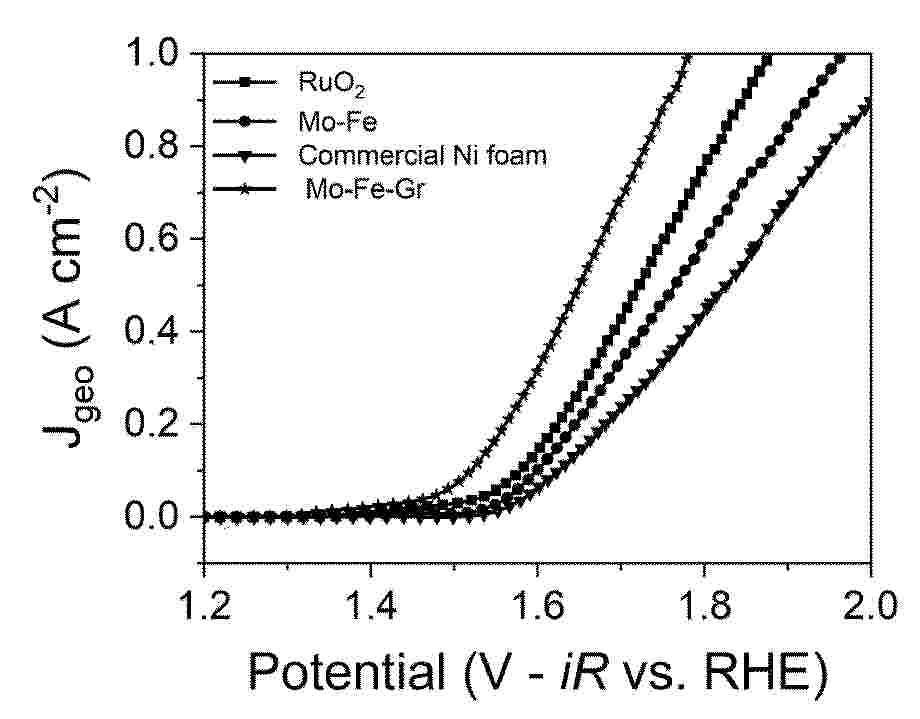
Resumen de: CN121472905A
本发明属于电极技术领域,具体涉及一种基于氮掺杂石墨烯负载钼铁单原子电极及其制备方法和应用。本发明先在泡沫镍气相沉积氮掺杂石墨烯,并在其表面电沉积铁钼单原子,泡沫镍基底上锚定具有铁钼单原子的催化剂,作为电解水制氢阳极用于析氧(OER)反应。本发明的制备方法不仅避免了使用绝缘粘结剂,确保了优异的电子传输能力,而且三维多孔结构极大地促进了电解液浸润和氧气气泡的快速释放,结合了多元金属的协同电子效应、最大的原子利用效率以及理想的质量传输通道,为开发高效、低成本的电解水制氢阳极提供了极具应用潜力的解决方案。
Resumen de: CN121475958A
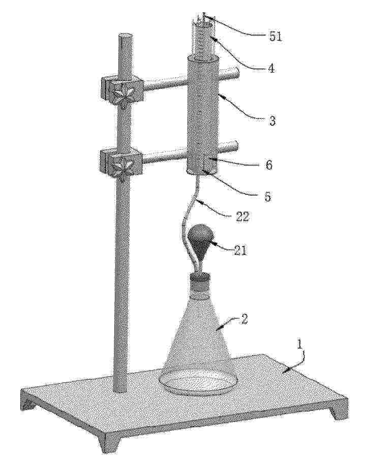
本发明涉及实验集气技术领域,本发明公开了一种铝颜料包覆层致密性的析氢测试装置及方法,包括铁架、反应瓶,所述反应瓶顶部封堵塞处固定连接有滴管,所述反应瓶的上方通过所述铁架固定连接有调浮集气组件,所述调浮集气组件由透明的环筒、透明的采集筒、顶气活塞、浮盒组成,所述浮盒的数量不少于1个,所述反应瓶、所述采集筒通过气管连通,所述环筒包围在所述采集筒的外部,所述顶气活塞密封滑动连接在所述采集筒的内部;采用非手触水的形式,利用浮力克服气封活塞摩擦力、活塞承受重力等对气体注入的阻碍问题,且经过调试后,即可进行多次且长期稳定运行,整体结构简单,成本低,符合实验应用需求。
Resumen de: CN121472897A
本发明公开一种基于纳米级梯度浆料分批次喷涂的PEM制氢膜电极及制备方法。本发明首先通过精确调控冰浴超声、超声波破碎及高压均质的工艺参数,制备出三种不同纳米级DLS粒径的催化剂浆料:第一IrOx浆料(5‑10 nm)、第二IrOx浆料(10‑15 nm)和第三IrOx/TiO2浆料(20‑40 nm);然后采用超声喷涂技术,按粒径由小到大的顺序,将三种浆料分批次依次喷涂于膜基底上,并精确控制各层铱负载量。本发明通过构建从致密到疏松的纳米级梯度催化层结构,有效增加了三相反应界面,降低了欧姆电阻与传质阻力,从而在显著降低贵金属用量的同时,大幅提升了膜电极的催化活性与析氧反应效率。
Resumen de: CN121472910A
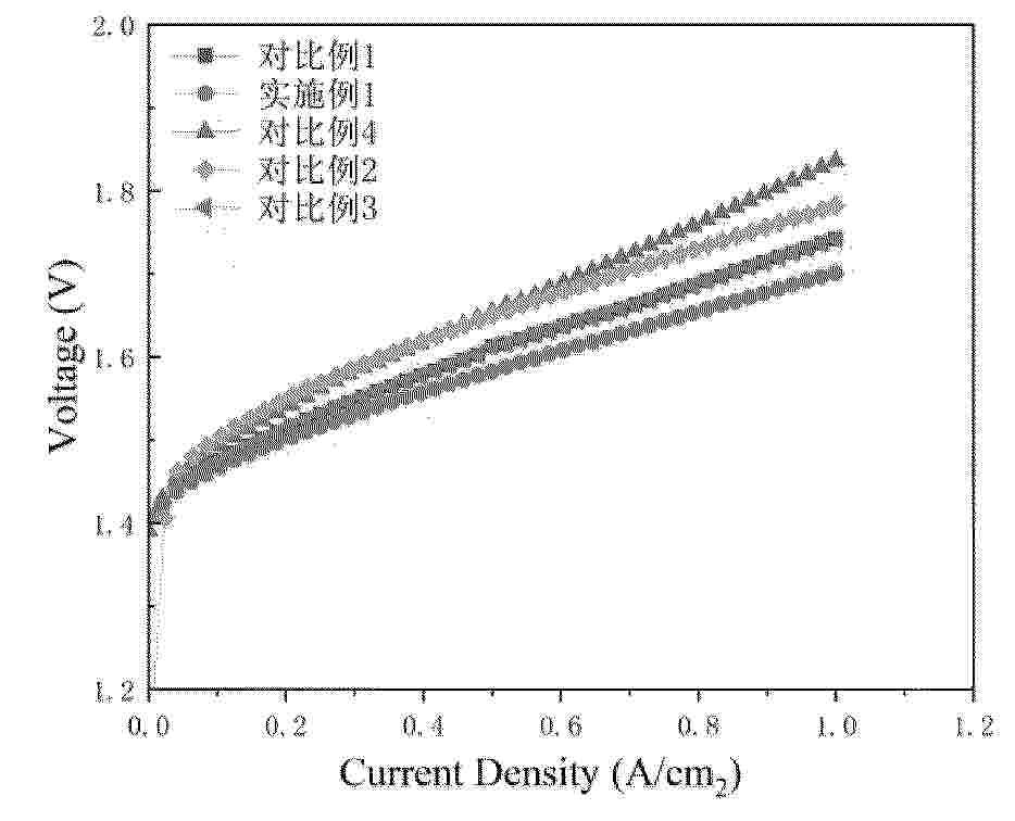
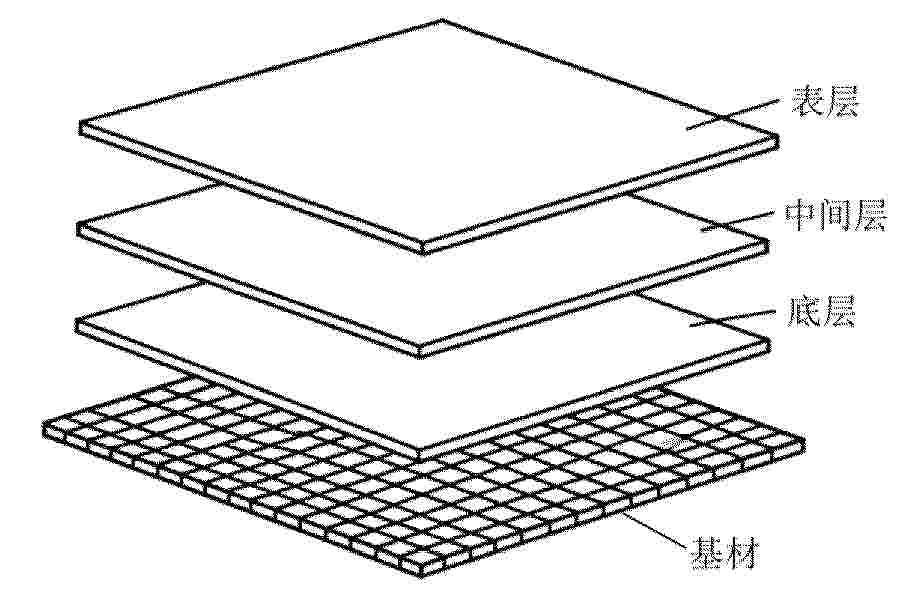
本发明属于电解水制氢领域,具体提供了一种电解水制氢领域阳极表面的涂层、阳极及阳极的制备方法和应用。本发明所提供的电解水制氢阳极表面的涂层包括依次设置的底层、中间层和表层;所述底层含有Ni和Cr;所述中间层含有Ni、Mo和Zn;所述表层含有RuO2和IrO2。本发明所述的阳极涂层,通过独特的梯度复合设计,含有特定成分的多层结构,所述底层、中间层和表层三层之间相互配合,协同达到与基材结合力强、电化学性能优异、制氢效率显著提高的技术效果。同时,本发明还提供了含有所述特定梯度涂层结构的阳极,以及所述阳极的制备方法和在电解水制氢中的应用。
Resumen de: CN119491243A
The invention relates to the technical field of household appliances, and provides a hydrogen peroxide generating device and application thereof. The hydrogen peroxide generating device comprises a shell, a liquid inlet and a liquid outlet, the liquid inlet and the liquid outlet are formed in the shell, the liquid inlet is used for being connected with a water supply component, a cathode piece and an anode piece which are used for electrolyzing water to generate a hydrogen peroxide solution are arranged in the shell, and the liquid outlet is used for discharging the generated hydrogen peroxide solution. According to the hydrogen peroxide generating device provided by the invention, water entering the shell through the liquid inlet can be electrolyzed to generate the hydrogen peroxide solution, and the generated hydrogen peroxide solution is discharged through the liquid outlet; the hydrogen peroxide generating device can be applied to household appliances such as clothes washing equipment, clothes processing equipment, an air conditioner, a dehumidifier, a refrigerator and a dish washing machine, can play a good role in cleaning, odor removal, disinfection, sterilization and the like, reduces the use of detergent, and improves the use experience of a user.
Resumen de: WO2024245759A1
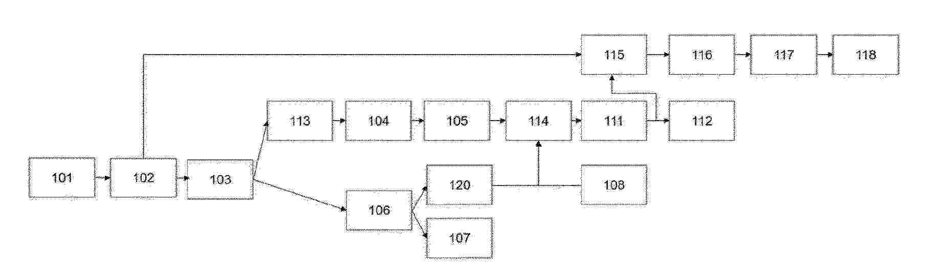
The proposed invention concerns a process (100) for producing a cracked gas product comprising hydrogen from an endothermic cracking reaction of an ammonia feedstock stream, comprising the following steps: • In a secondary reactor, performing a secondary endothermic cracking conversion (104) of the remaining unconverted portion of ammonia into a hydrogen enriched fuel gas, • Redirecting the hydrogen enriched fuel gas to a fuel device (105), in particular comprising a burner, arranged to perform a combustion reaction (111) of said hydrogen enriched fuel gas, potentially with an additional fuel gas stream, • Heating the main endothermic cracking conversion (112) with heat provided by said combustion.
Resumen de: KR20260017874A
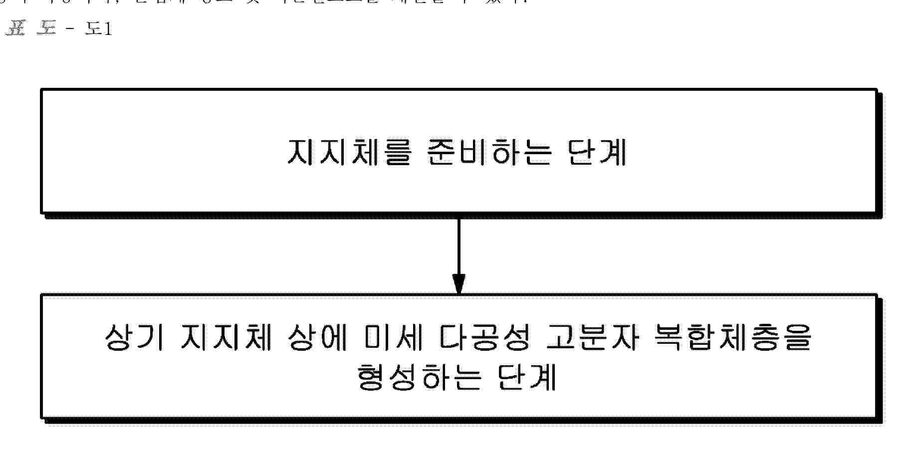
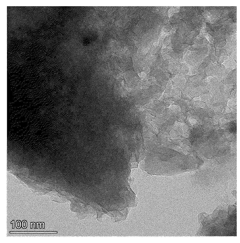
본 발명은 지지체; 및 상기 지지체 상에 형성된 미세다공성 고분자 복합체층;을 포함하고, 상기 미세다공성 고분자 복합체층은 미세다공성 고분자 및 이온성 액체를 포함하는, 수전해용 이온교환막 및 이의 제조 방법에 관한 것이다. 본 발명의 수전해용 이온교환막의 제조 방법은 제조 공정이 간단하기 때문에 모든 형태의 이온교환막에 적용이 가능하며, 손쉽게 강도 및 이온전도도를 개선할 수 있다.
Resumen de: CN121472921A
本发明公开了一种具有高抗电力波动性能的铁钴铝硫化物析氢催化剂及其制备方法和应用,涉及电催化全水分解技术领域,为解决现有技术中缺少高HER活性、耐受工业级电流密度、并在波动电力条件下保持稳定的催化剂。本发明技术要点包括:首先在载体表面通过电化学沉积尿素及铁、钴和铝的层状金属氢氧化物;再以层状金属氢氧化物为基体,通过水热原位硫化处理得到铁钴铝硫化物复合材料。本发明复合材料在制备电解制氢阴极材料中具有广泛的应用前景。
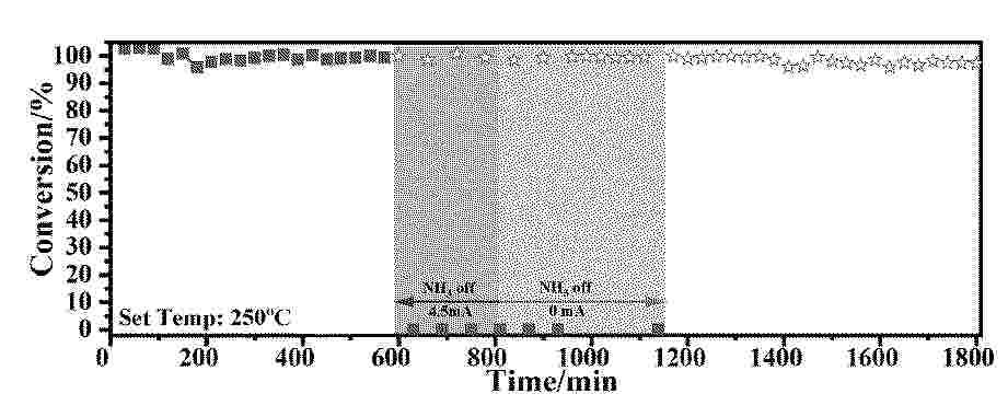
Resumen de: CN121467028A
本发明涉及一种热触发的电场催化氨低温分解制氢催化剂及其制备方法和用用,该催化剂包括载体、活性组分和导电材料添加剂,活性组分的负载量为催化剂总重量的0.1‑10%,导电材料添加剂的添加量为催化剂总重量的0%‑5%;其中,所述载体为铈锆固溶体;活性组分为Ru、Pd、Ag、Pt、Rh、Ir、Cr、Mn、Fe、Co、Ni、Cu中的一种或多种;导电材料添加剂为导电碳材料。与现有技术相比,本发明具有启用停止快速且稳定、长时间运行后氨转化率衰减小等优点。
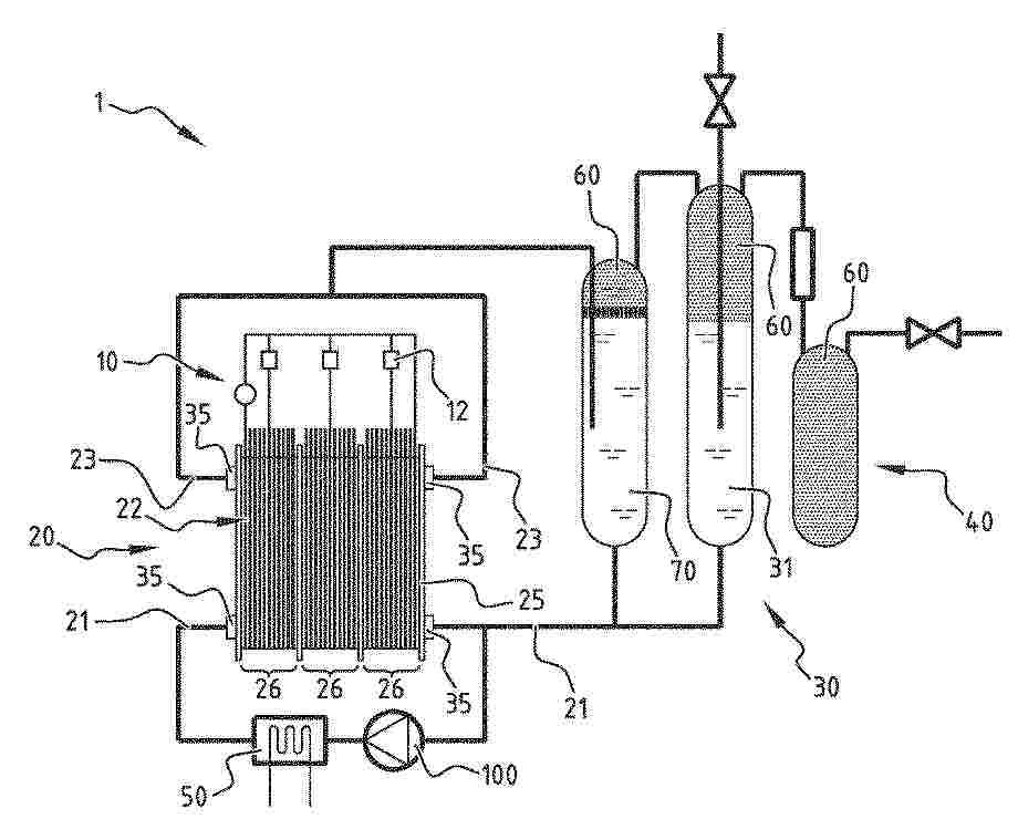
Resumen de: WO2024231154A1
The present invention relates to a hydrogen gas production assembly comprised of a hydrogen gas production device, a container comprising an aqueous electrolyte solution, a storage container for storing produced hydrogen gas an input providing the aqueous electrolyte solution from the container to the hydrogen gas production device and an output for transferring produced hydrogen gas from the hydrogen gas production device to the storage container. The present invention further relates to methods for the production of hydrogen gas via the hydrogen gas production assembly.
Resumen de: CN121472927A
本发明属于电解水制氢催化材料技术领域,具体涉及一种析氧反应催化剂及其制备方法和应用。所述催化剂的化学通式为M‑M1M2 LDH,其中M1、M2分别为Fe、Co、Ni中的一种,且M1和M2不为同一元素,M为V、Cr、Mn、Co、Cu、Zn、Mo、Ce、Zr中的一种;采用溶胶‑凝胶法制备。本发明通过可控掺杂过渡金属元素优化层状双氢氧化物电子结构,合成粒径在5nm以下的过渡金属元素掺杂的层状双氢氧化物,用于析氧反应催化剂,具有良好的电催化活性。该材料制备工艺简单、成本低廉,为高效稳定电解水催化剂的开发和规模化生产提供了新策略。
Resumen de: CN121472889A
本发明涉及制氢设备技术领域,具体为基于非贵金属催化剂的光热电解耦合制氢装置:包括制氢底座,所述制氢底座的表面上设置有电解槽,所述制氢底座的表面上固定连接有总控制器,所述制氢底座的表面上固定连接有供电电源,所述供电电源的输出端固定连接有电源线,所述电源线的输入端固定连接有电极,所述电极固定连接在电解槽的外部,所述电解槽的表面上固定连接有排气管。本发明通过在关键管道设置第一电磁阀、第二电磁阀等多个电磁阀,并结合第一温度传感器等传感器实时监测温度,配合上总控制器控制,形成循环交流水道,针对电解槽内部温度,灵活调整水道水流方向,满足反应温度要求,显著提高制氢效率。
Nº publicación: CN121472920A 06/02/2026
Solicitante:
青岛万源生物科技有限公司
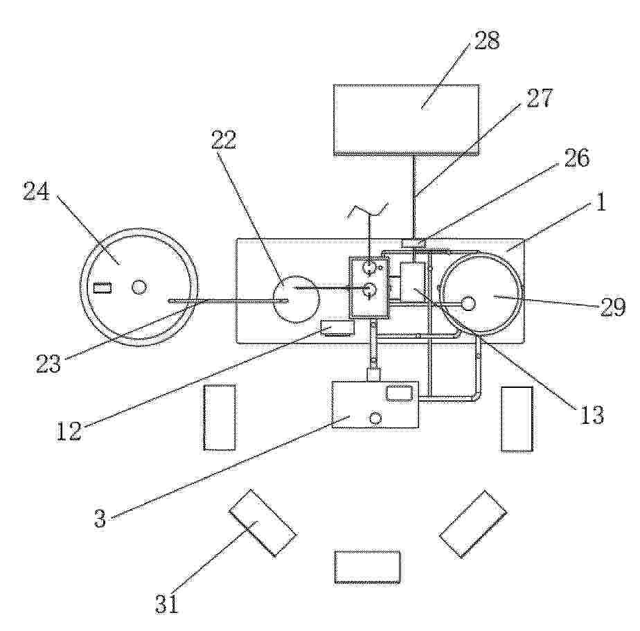
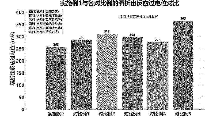
Resumen de: CN121472920A
本发明公开了一种海水制氢催化剂制备方法及系统,属于海水制氢技术领域。方法包括基底预处理、梯度合金核层制备、三元渗透阻挡层制备、相变织构化处理和电场辅助表面改性。通过梯度磁场和超声波协同辅助电化学沉积技术制备原子排列有序的镍铁钴三元合金层,采用原子层沉积技术按钨层、钼层、铬层顺序制备三元渗透阻挡层,有效阻止氯离子侵蚀。系统包括基底预处理装置、梯度合金核层制备装置、三元渗透阻挡层制备装置、相变织构化处理装置和电场辅助表面改性装置。本发明制备的催化剂具有高催化活性、快反应动力学、大活性面积、低电荷转移电阻和强抗腐蚀稳定性,在海水电解环境中表现出优异的长期稳定性。
 BOPI
BOPI
 Sede Electrónica