Si deseas distinguir tus productos, servicios o ambos de los de otra empresa, es posible que necesites una marca o nombre comercial. Descubre qué son, en qué consiste su procedimiento de registro y qué implica.

Información sobre los plazos de presentación de solicitudes de transformación de marcas de la Unión Europea en marca nacional española. Más información


Si tienes un nuevo dispositivo, producto o procedimiento que resuelva un problema técnico o tenga una ventaja práctica, existen distintas formas de protegerlo en España y en otros países. Descubre cómo hacerlo.

¿Tu innovación reside en la estética, la ornamentación o la apariencia de tu producto? Protégela mediante un diseño industrial. Descubre qué derechos confiere el registro y cómo realizar la tramitación.

Las indicaciones geográficas protegen el nombre de un producto originario de una zona geográfica, a la cual le debe una determinada calidad, reputación u otra característica. Descubre qué son, en qué consiste su procedimiento de registro y qué beneficios conceden.

Las patentes publicadas en todo el mundo son una valiosa fuente de información científica, técnica y comercial.

Si eres emprendedor/a o una empresa y quieres potenciar y mejorar la rentabilidad de tu negocio protegiendo de forma adecuada los activos intangibles de tu organización, en este espacio encontrarás lo necesario.


 839
resultados
839
resultados
 Última actualización
05/05/2026 [07:06:00]
Última actualización
05/05/2026 [07:06:00]


Resumen de: WO2025033908A1
The present invention relates to an oxygen evolution reaction (OER) oxide catalyst for anion exchange membrane (AEM) water electrolysis, doped with various metal atoms by using a co-precipitation method, and to a method for preparing same.

Resumen de: WO2025127526A1
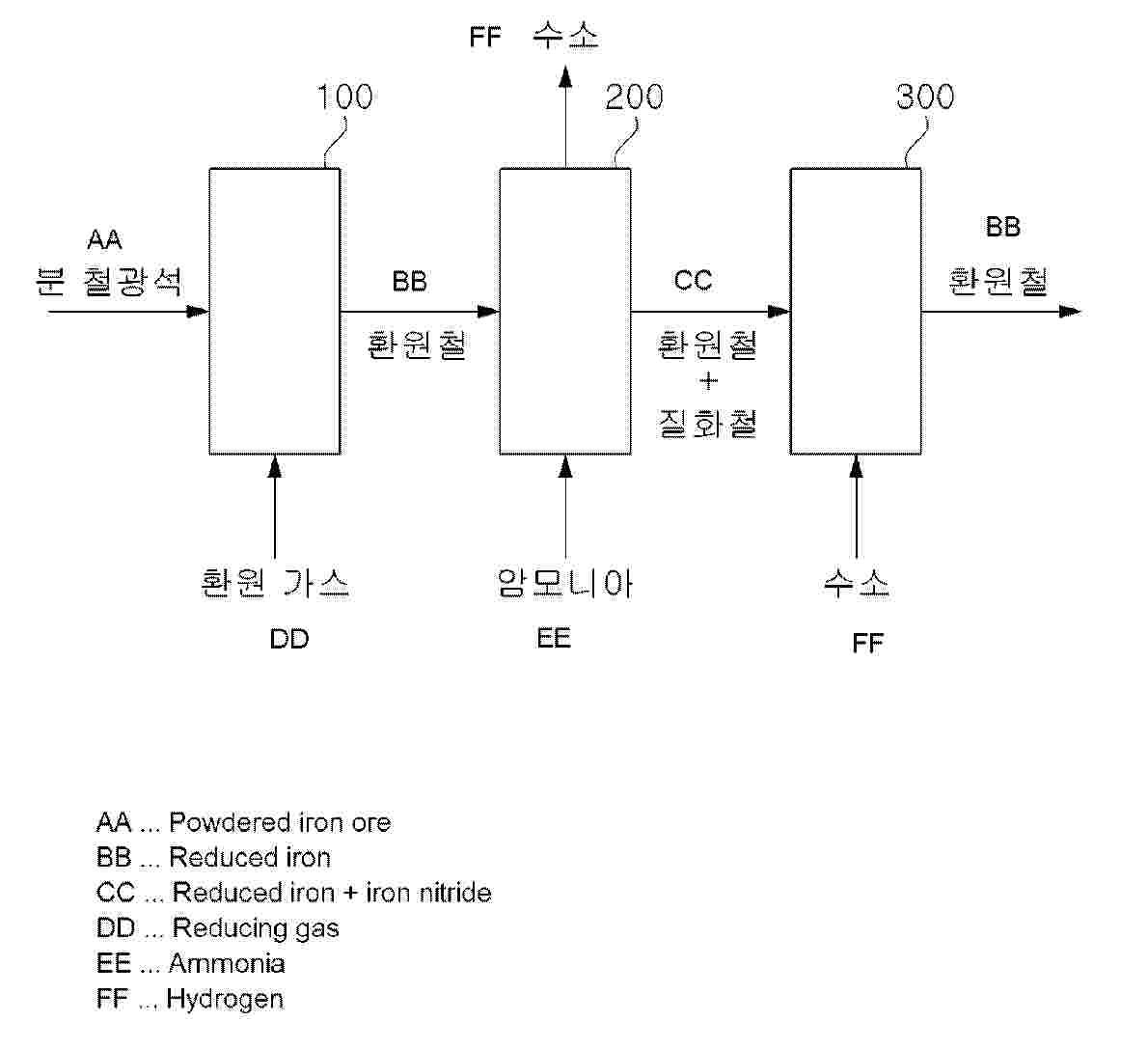
According to exemplary embodiments of the present invention, a hydrogen production system is provided. The present invention comprises: a hydrogen generation unit configured to receive reduced iron from a reduced iron generation unit configured to generate reduced iron by reducing powdered iron ore in a reducing gas atmosphere, and to generate hydrogen from ammonia by bringing the reduced iron into contact with the ammonia; and a regeneration unit configured to receive the reduced iron from the hydrogen generation unit and to regenerate the reduced iron by reducing the reduced iron in a hydrogen gas atmosphere. According to other exemplary embodiments of the present invention, a method for producing hydrogen is provided.
Resumen de: WO2024161039A1
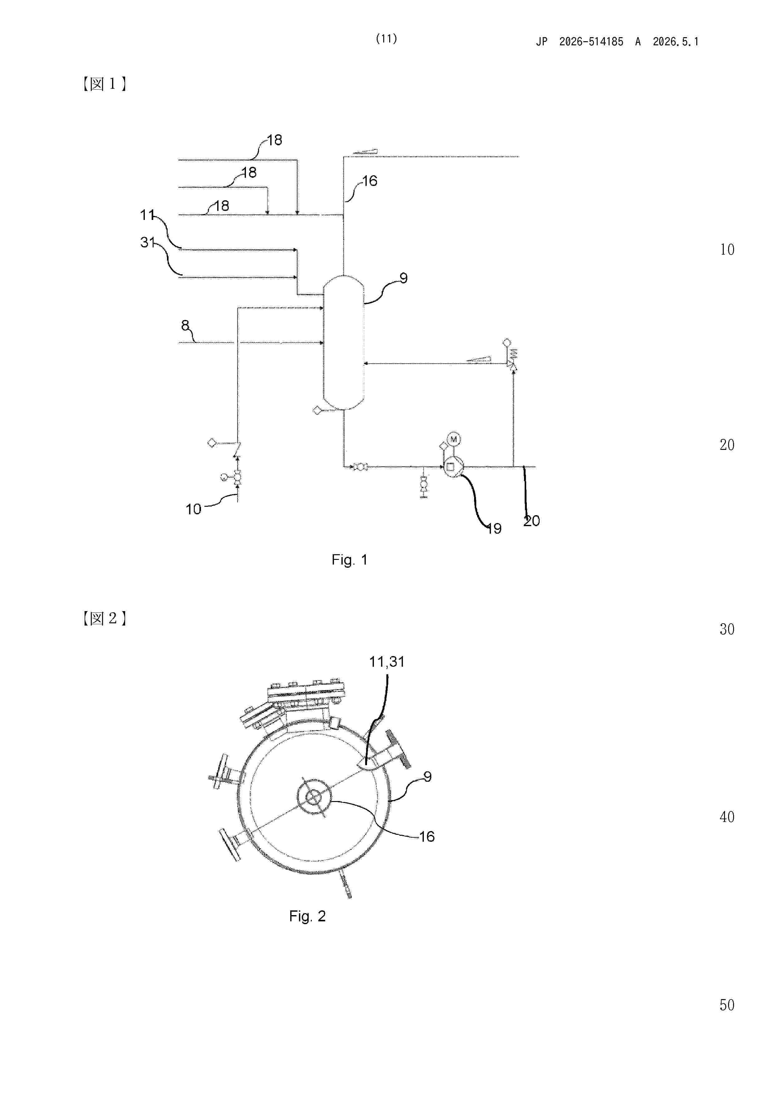
Feedwater preparation system in a water electrolyser adapted to produce hydrogen and oxygen in one or more pressurised electrolyser stacks (2) using alkaline water and comprising a product gas conditioning system that has a safety valve out-blow material stream pipe (11) which is connected to a feedwater vessel (9), and/or has a depressurisation stream pipe (31) from a gas cleaning vessel which is connected to the feedwater vessel (9).
Resumen de: WO2024175690A1
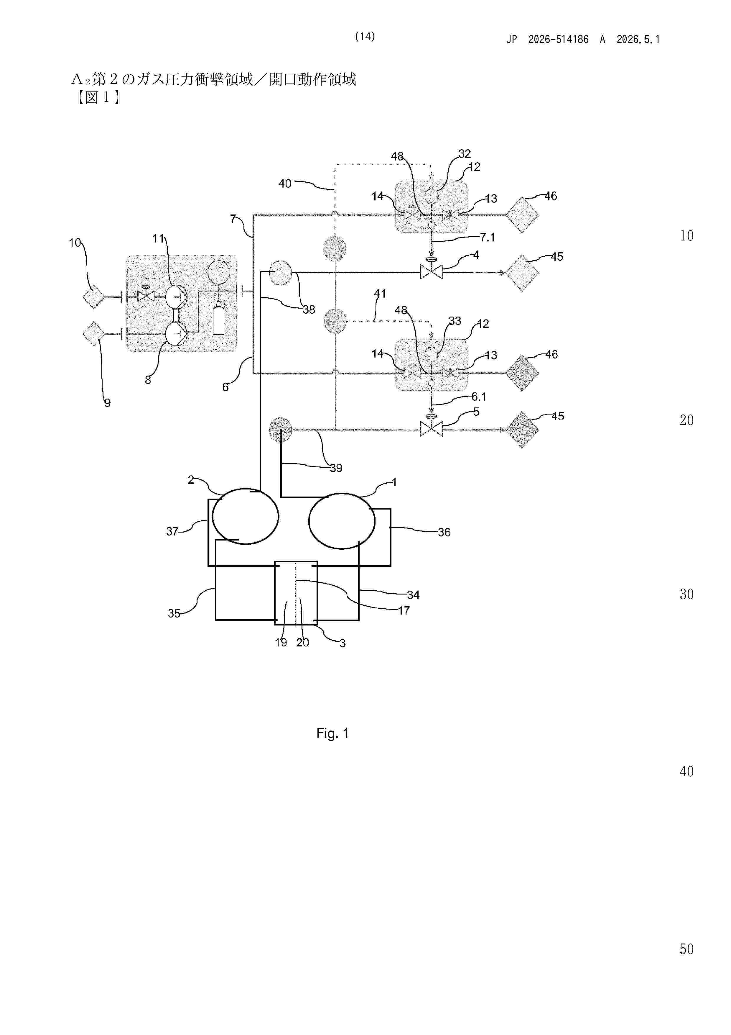
In a gas pressure balance method in an electrolyser system a predefined pressure difference between pressures in an oxygen gas separation tank and a hydrogen gas separation tank is maintained by controlled release of gases through an oxygen back pressure valve and a hydrogen back pressure valve. in a first step, for each of the oxygen back pressure valves and the hydrogen back pressure valves, a predefined, calibrated pilot gas pressure is generated and in a second step, the predefined, calibrated pilot gas pressures are forwarded to the respective back pressure valves and in a third step, hydrogen and oxygen gasses are released whenever the gas pressures in the hydrogen and oxygen separation tanks exceeds the predefined, calibrated pilot pressure in the respective pilot gas streams.
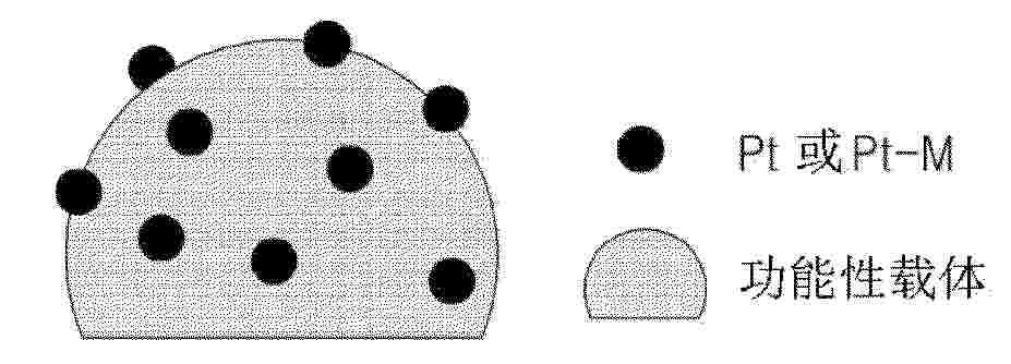
Resumen de: WO2025071231A1
The present invention relates to a catalyst composite and a polymer electrolyte membrane including same, wherein the catalyst composite is manufactured by complexing platinum and a metal having a higher ionization tendency than platinum with a functional support. When applied to a polymer electrolyte membrane, the catalyst composite effectively reduces the gas permeating from the counter electrode.
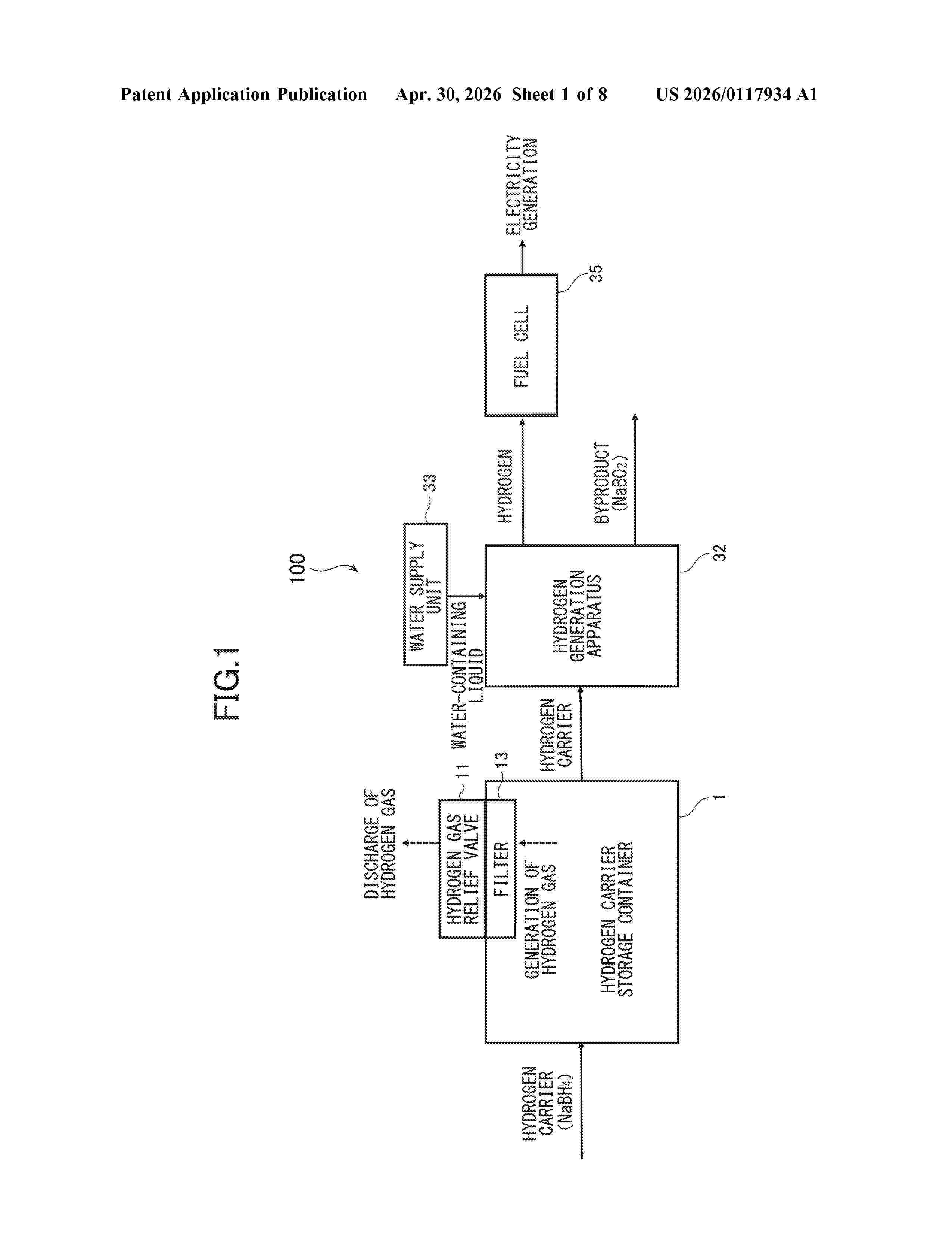
Resumen de: US20260117934A1
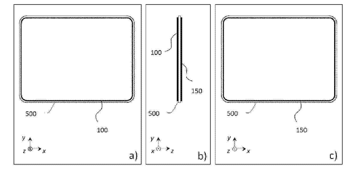
A pair of flat portions is provided on both sides of an outer wall surface of a storage container, respectively, in at least one of an up-down direction, a left-right direction, and a front-rear direction in an installed state of the storage container. A recess is formed at a portion of at least one of the pair of flat portions, and is formed so as to be recessed inward with respect to another portion of the flat portion and to at least partially communicate with the outside of the flat portion in a direction along the flat portion. A relief valve is provided in the recess and is automatically opened in a case where a pressure inside a storage portion for storing a hydrogen carrier exceeds a predetermined value to release gas inside the storage portion to the outside.
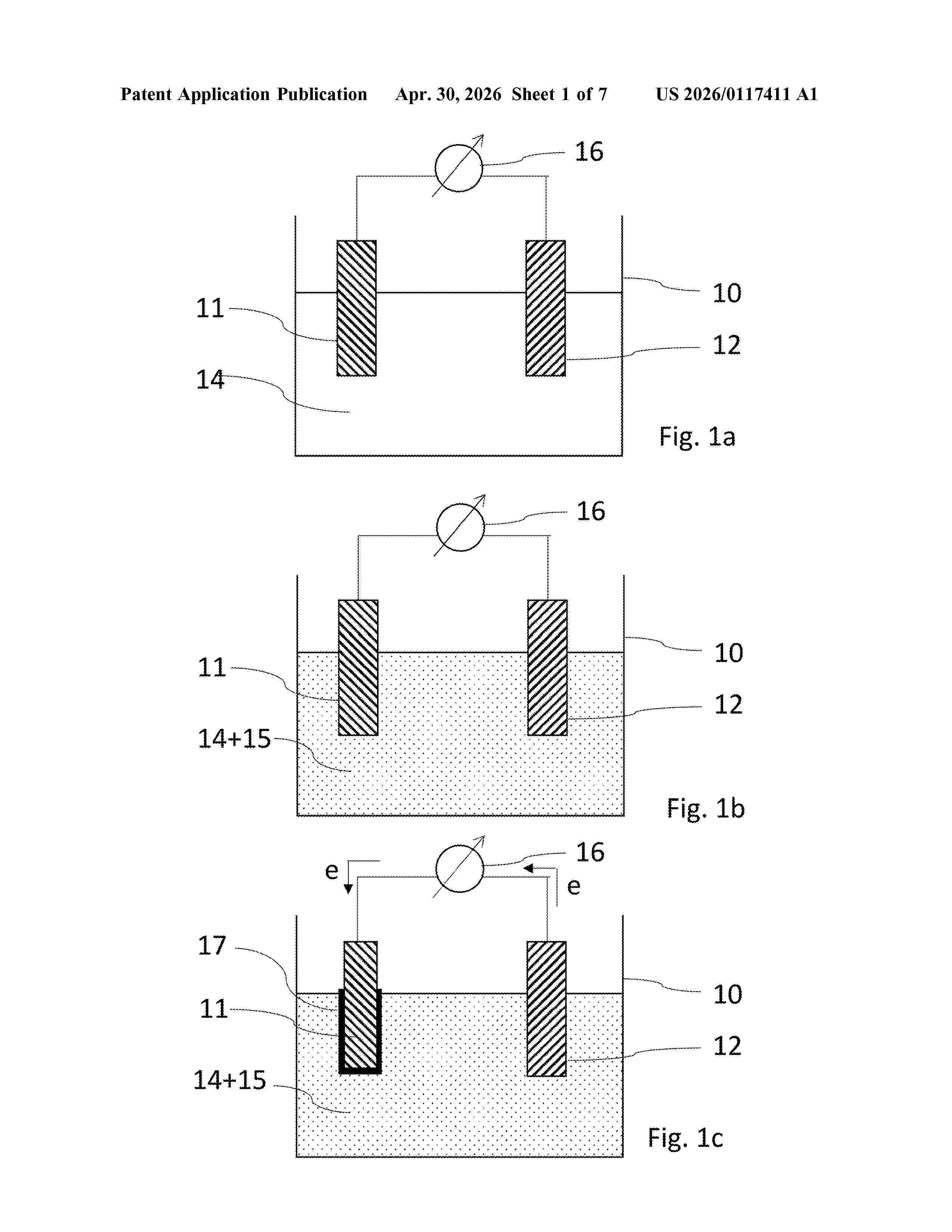
Resumen de: US20260117411A1
A process for producing a graphite-containing metal oxide electrode includes: a) providing an electrolysis cell having an electrode, a further electrode and an aqueous and/or non-aqueous carbonyl-and cyano-free solvent, b) introducing black matter and a proton source into the solvent present in the electrolysis cell, where the black matter includes graphite-supported precious metal-free metal oxides, and c) applying a voltage to the electrode and the further electrode, such that the precious metal-free metal oxides and graphite provided by means of the black matter are deposited on the electrode to produce a graphite-containing metal oxide coating on the electrode for formation of the graphite-containing metal oxide electrode. The graphite-containing metal oxide electrode is used for production of hydrogen and/or oxygen by (photo)electrochemical water splitting and to an electrolysis cell for production of hydrogen and oxygen by (photo)electrochemical water splitting.
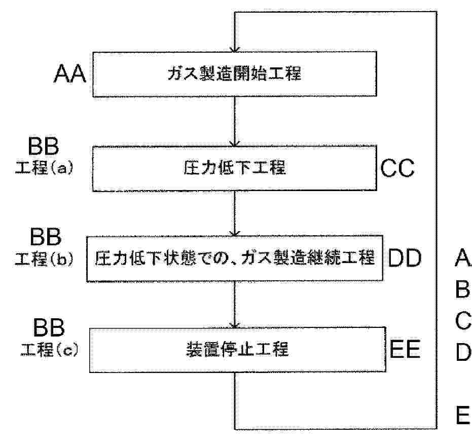
Resumen de: WO2024257717A1
This method for stopping a gas production device is a method for electrolyzing an electrolytic alkali solution under pressurized conditions in which the electrolytic solutions that have flowed out of an anode chamber and a cathode chamber are circulated so as to flow again into the anode chamber and the cathode chamber, and comprises stopping the operation of the device through a procedure including given steps. This method makes it possible to prevent a gas composition from reaching an explosion limit.
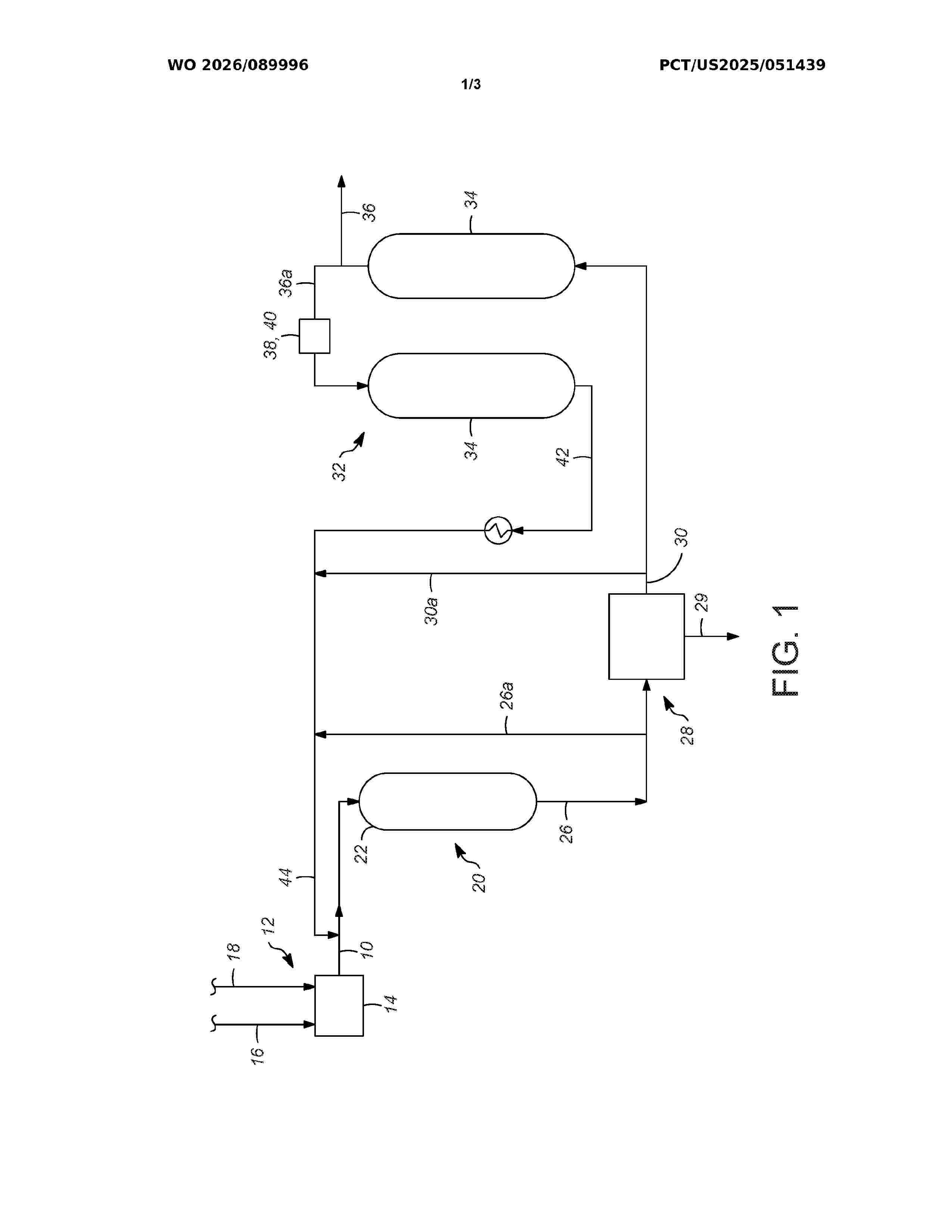
Resumen de: WO2026089996A1
Processes and apparatuses for controlling a temperature of a reactor. Oxygen and hydrogen are reacted in a reactor which contains a catalyst configured to catalyze a reaction between oxygen and hydrogen and produce an effluent comprising water. Water is removed from the effluent in a separation zone having a plurality of vessels containing an adsorbent configured to adsorb water and provide a purified product stream, the purified product stream comprises oxygen or hydrogen. An exotherm of the reactor is controlled by recycling a recycled stream which comprises a portion of the effluent stream or a portion of the purified product stream.
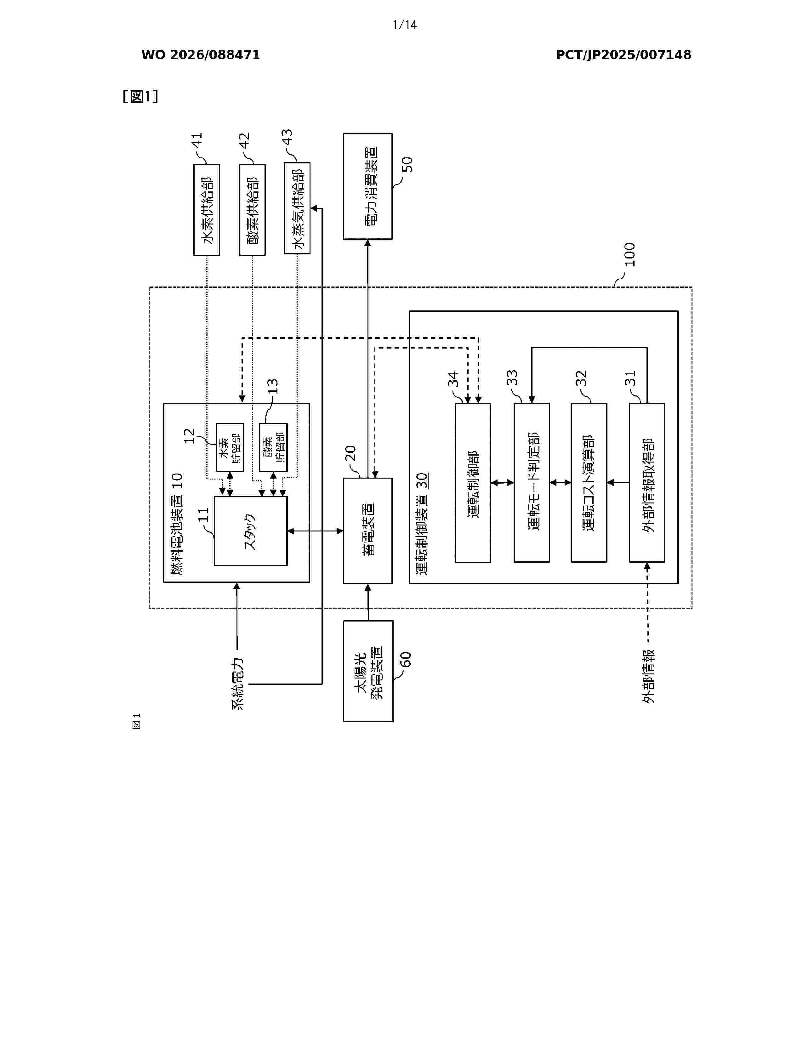
Resumen de: WO2026088471A1
This operation control device, which controls the operation of a fuel cell device, is configured to comprise: an external information acquisition unit that acquires external information including market electricity and hydrogen prices used to operate the fuel cell device; an operation cost calculation unit that calculates power generation cost in a fuel cell mode using the hydrogen price, hydrogen generation cost in an electrolysis mode using the electricity price, operation switching profit based on the power generation cost or the hydrogen generation cost, and operation switching loss resulting from switching between the fuel cell mode and the electrolysis mode; an operation mode determination unit that determines to switch the operation mode when the difference between the operation switching profit and the operation switching loss exceeds a determination threshold value; and an operation control unit that controls the operation on the basis of the determination made by the operation mode determination unit.
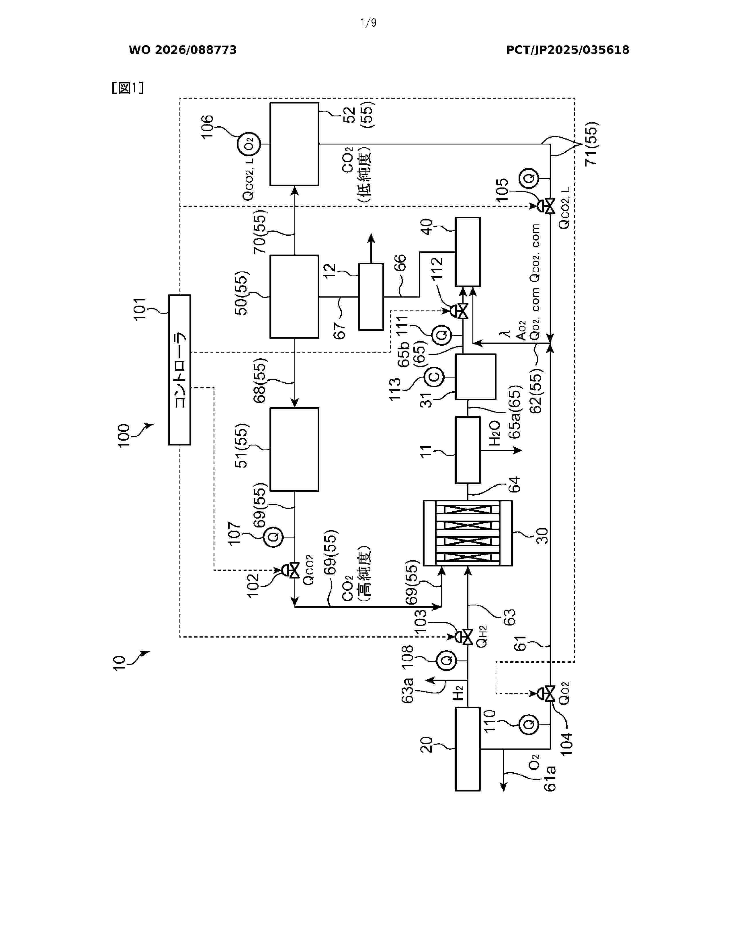
Resumen de: WO2026088773A1
A thermal energy generation system (10) is provided with: a water electrolysis device (20); a methanation device (30) that generates methane and water by causing carbon dioxide to react with hydrogen generated by the water electrolysis device (20); a combustion device (40) that combusts the methane discharged from the methanation device (30) using a combustion gas containing oxygen discharged from the water electrolysis device (20); and a CO2 distribution unit (55) that distributes and supplies the carbon dioxide discharged from the combustion device (40) to the methanation device (30) and the combustion device (40), respectively. The methanation device (30) causes a methanation reaction to be performed using the carbon dioxide from the CO2 distribution unit (55). The combustion device (40) causes a combustion reaction to be performed by including the carbon dioxide from the CO2 distribution unit (55) in the combustion gas.
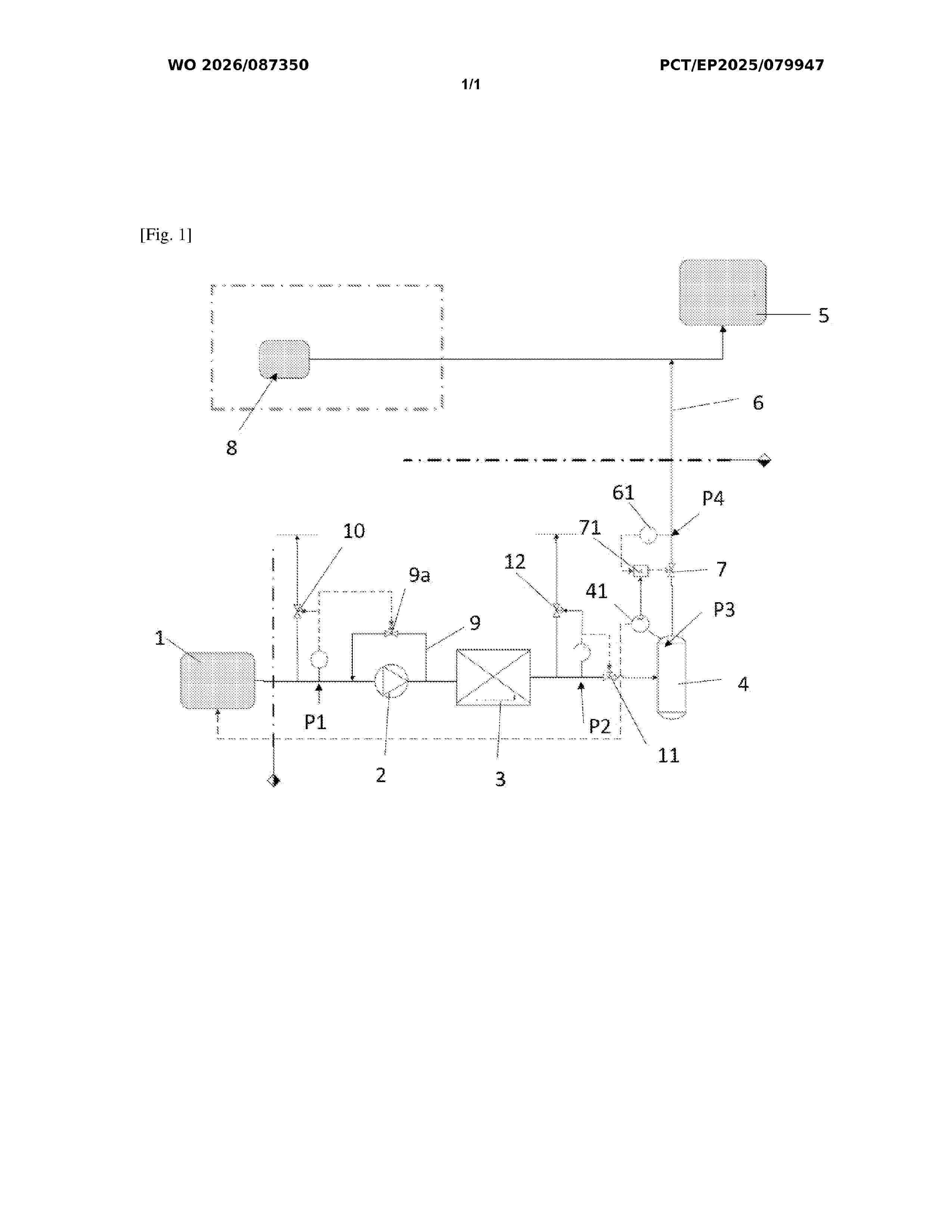
Resumen de: WO2026087350A1
The present invention relates to the field of industrial production of dihydrogen and more particularly to a dihydrogen production installation (H2) intended to supply an installation using dihydrogen and a method for controlling said installation.
Resumen de: WO2025002638A1
The present invention relates to a divided cell for alkaline water electrolysis, where the separator is equipped with a gasket having anisotropic elastic properties and exhibiting reduced gasket deformation along the plane of the major surface of the separator when subject to a compression force perpendicular to that plane. The invention also relates to an electrolyser comprising a plurality of cells as hereinbefore described.
Resumen de: EP4733447A1
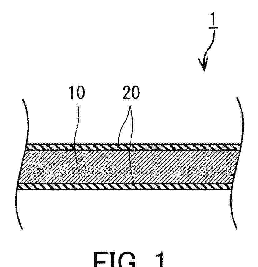
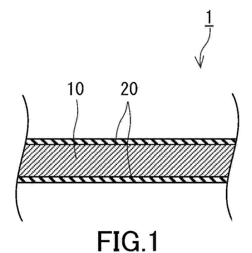
0001 A water electrolysis electrode 1 includes an electroconductive substrate 10 and a layered double hydroxide layer 20. The layered double hydroxide layer is disposed on a surface of the electroconductive substrate 10. An extinction coefficient k<800> of the layered double hydroxide layer 20 at an wavelength of 800 nm is 0.08 or more.
Resumen de: EP4733448A1
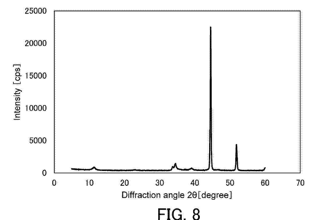
0001 A water electrolysis electrode 1 includes an electroconductive substrate 10 and a layered double hydroxide layer 20. The layered double hydroxide layer 20 is disposed on a surface of the electroconductive substrate 10. The layered double hydroxide layer 20 includes Ni. In a diffraction pattern obtainable by grazing incidence X-ray diffraction measurement of the layered double hydroxide layer, a diffraction peak height P<012> of a (012) plane is higher than a diffraction peak height P<003> of a (003) plane.
Resumen de: EP4733451A1
A water electrolysis electrode 1 includes an electroconductive substrate 10 and a layered double hydroxide (LDH) layer 20. The layered double hydroxide layer 20 is formed on a surface of the electroconductive substrate 10. An effective film thickness of the layered double hydroxide layer 20 is 250 nm or more and less than 4000 nm. The layered double hydroxide layer 20 may include layered double hydroxide 20a. The effective film thickness of the layered double hydroxide layer 20 may be 3470 nm or less.
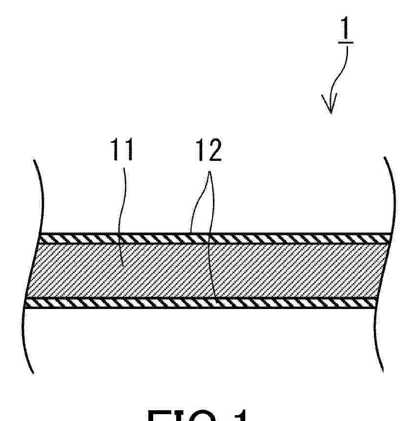
Resumen de: EP4733442A1
A water electrolysis electrode 1 includes a conductive substrate 11 and a layered double hydroxide layer 12. The layered double hydroxide layer 12 is disposed on a surface of the conductive substrate 11. The layered double hydroxide layer 12 includes two or more transition metals. The layered double hydroxide layer 12 includes a chelating agent.
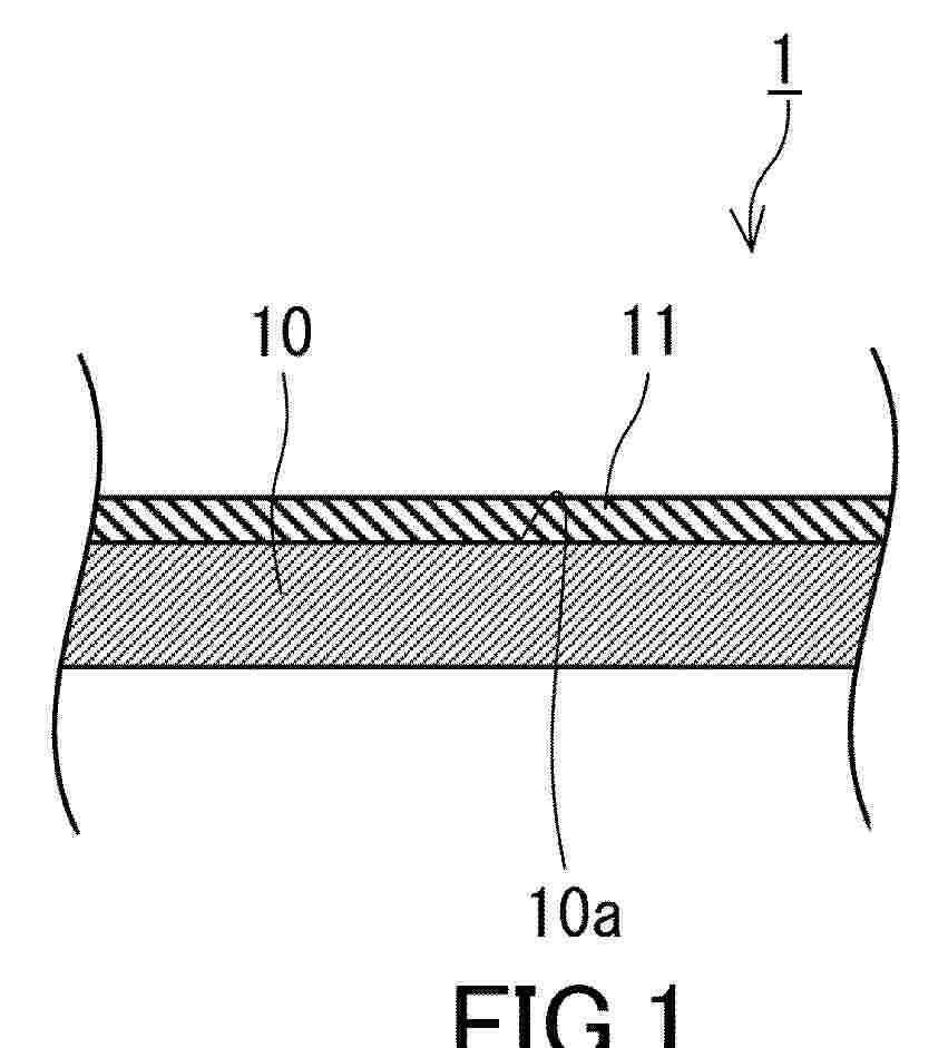
Resumen de: EP4733444A1
A water electrolysis electrode 1 includes a conductive substrate 10 and a layered double hydroxide layer 11. The conductive substrate 10 has a surface 10a including nickel having a (111) plane orientation. The layered double hydroxide layer 11 includes a layered double hydroxide including two or more transition metals. The layered double hydroxide layer 11 is disposed on the surface 10a.
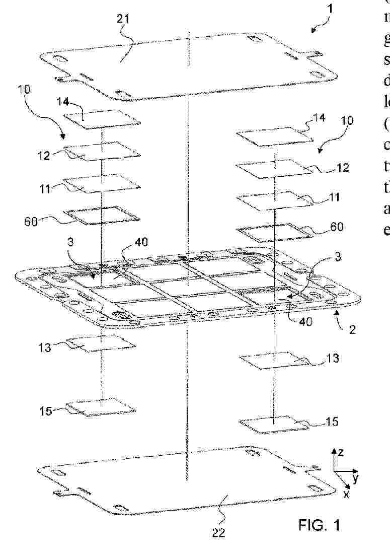
Resumen de: WO2024261689A1
Electrolyser device (1), of the type which uses the anion exchange membrane water electrolysis (AEMWE) technology for the production of hydrogen, characterized in that it comprises: - at least one support frame (2) with a substantially laminar development, comprising at least two seats (3) which are defined on the same support frame (2) so as not to overlap with each other, - at least two electrochemical modules (10) wherein: - each electrochemical module (10) is mounted at a respective seat (3), - each electrochemical module (10) includes an anion exchange separation membrane (11) which is interposed between two electrodes, respectively between an anode (12) and a cathode (13), - at least the separation membranes (11 ) of said at least two electrochemical modules (10) are structurally distinct and separated from each other, means (20) for applying electrical energy to the electrodes (12, 13) of each electrochemical module (10).
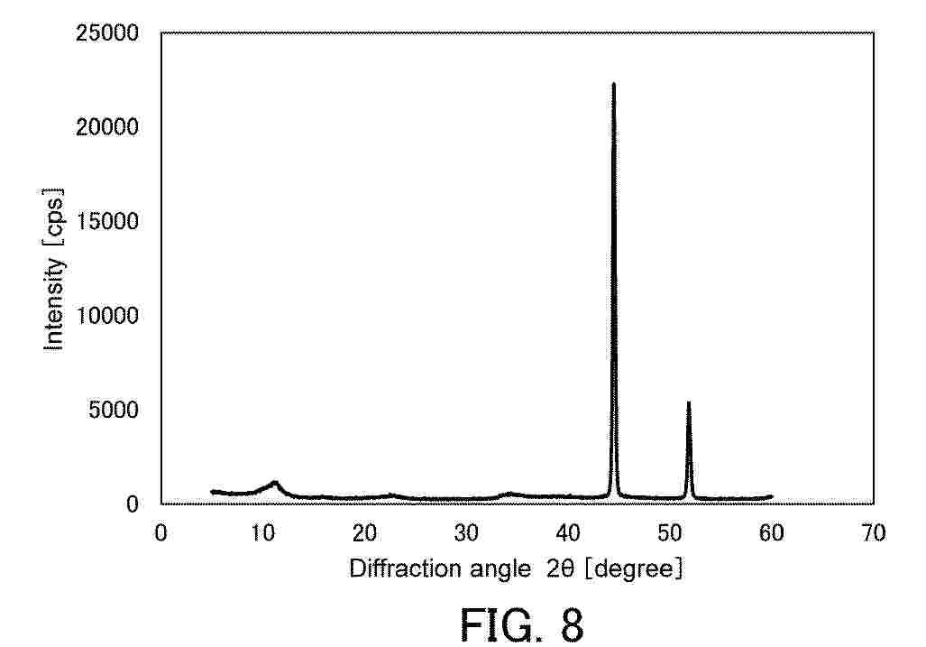
Resumen de: EP4733449A1
0001 A water electrolysis electrode 1 includes an electroconductive substrate 10 and a layered double hydroxide layer 20. The electroconductive substrate 10 includes Ni. The layered double hydroxide layer 20 is disposed on a surface of the electroconductive substrate 10. The layered double hydroxide layer 20 includes Ni. In a XRD pattern of grazing incidence X-ray diffraction for the water electrolysis electrode 1, a ratio P<003>/P<111> of a diffraction peak intensity P<003> of a (003) plane of a layered double hydroxide to a diffraction peak intensity P<111> of a (111) plane of Ni is 0.025 or less.
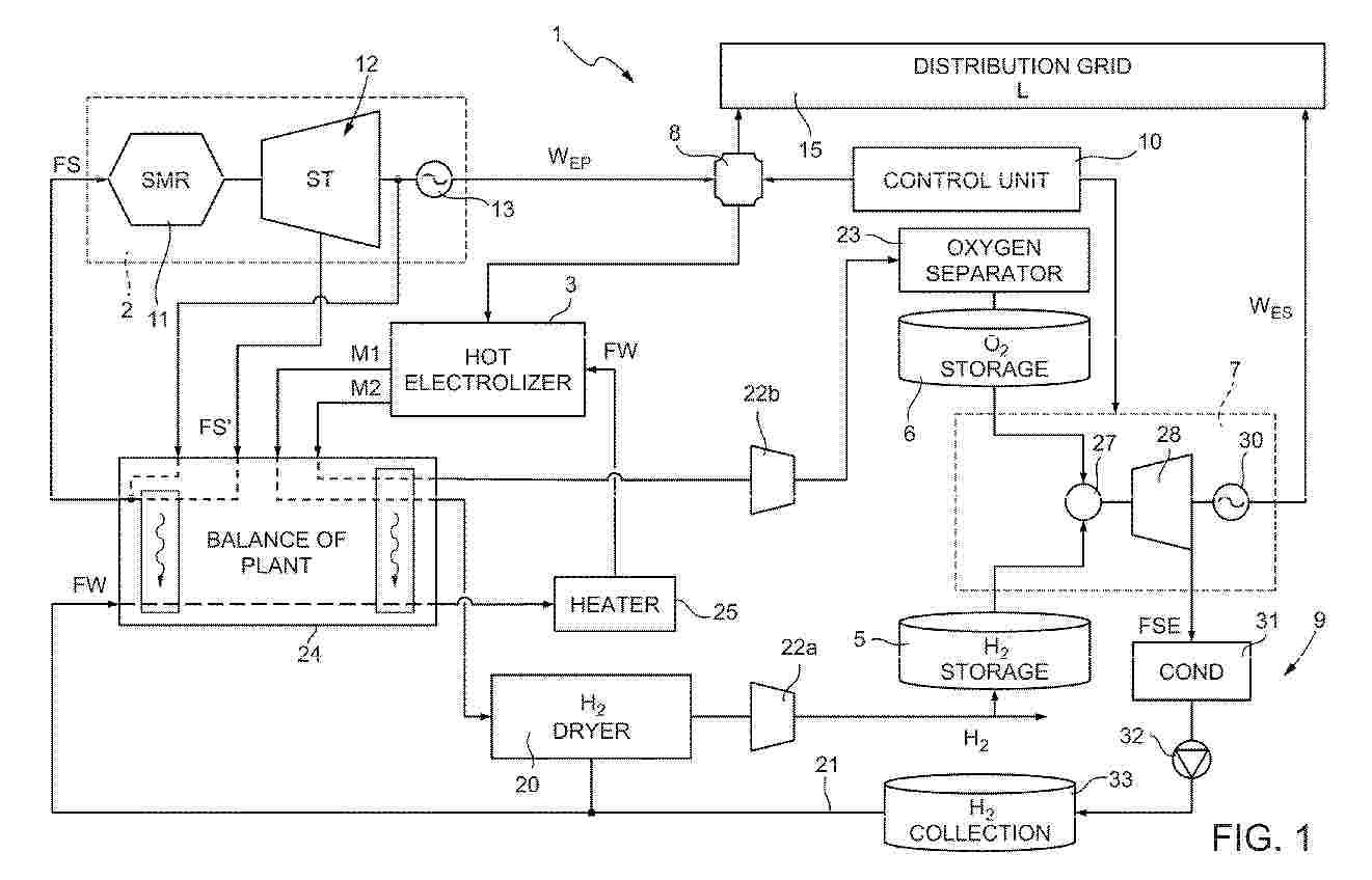
Resumen de: EP4734318A1
A hybrid power plant includes a nuclear source generator assembly (2), configured to provide a primary electric power (WEP) from a nuclear source; an electrolyzer (3) operable to produce a first mixture (M1) containing hydrogen and a second mixture (M2) containing oxygen from a water flow (FW); a hydrogen storage system (5), coupled to the electrolyzer (3) to receive hydrogen from the first mixture (M1); an oxygen storage system (6), coupled to the electrolyzer (3) to receive oxygen from the second mixture (M2); and a hydrogen generator assembly (7), operable to produce a secondary electric power (WES) using the hydrogen from the hydrogen storage system (5) and the oxygen from the oxygen storage system (6). A power divider (8), coupled to a distribution grid (15) and to the electrolyzer (3), is configured to controllably divide the primary electric power (WEP) between the distribution grid (15) and the electrolyzer (3).
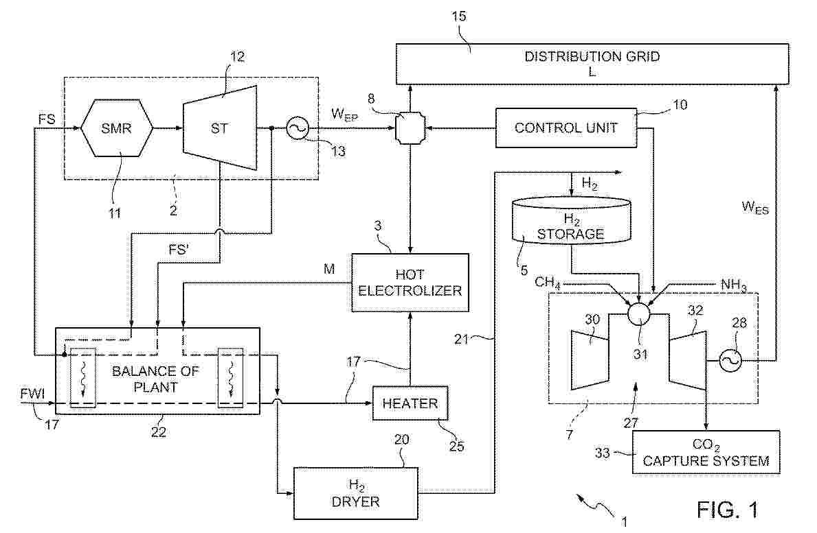
Resumen de: EP4734316A1
A hybrid power plant includes a nuclear source generator assembly (2), configured to provide a primary electric power (WEP) from a nuclear source; an electrolyzer (3) operable to produce a mixture (M) containing hydrogen from an inlet water flow (FWI) in the vapour and/or liquid phase; a hydrogen storage system (5), coupled to the electrolyzer (3) to receive hydrogen from the mixture (M); and a hydrogen generator assembly (7), operable to produce a secondary electric power (WES) using the hydrogen from the hydrogen storage system (5). A power divider (8), coupled to a distribution grid (15) and to the electrolyzer (3), is configured to controllably divide the primary electric power (WEP) between the distribution grid (15) and the electrolyzer (3) .
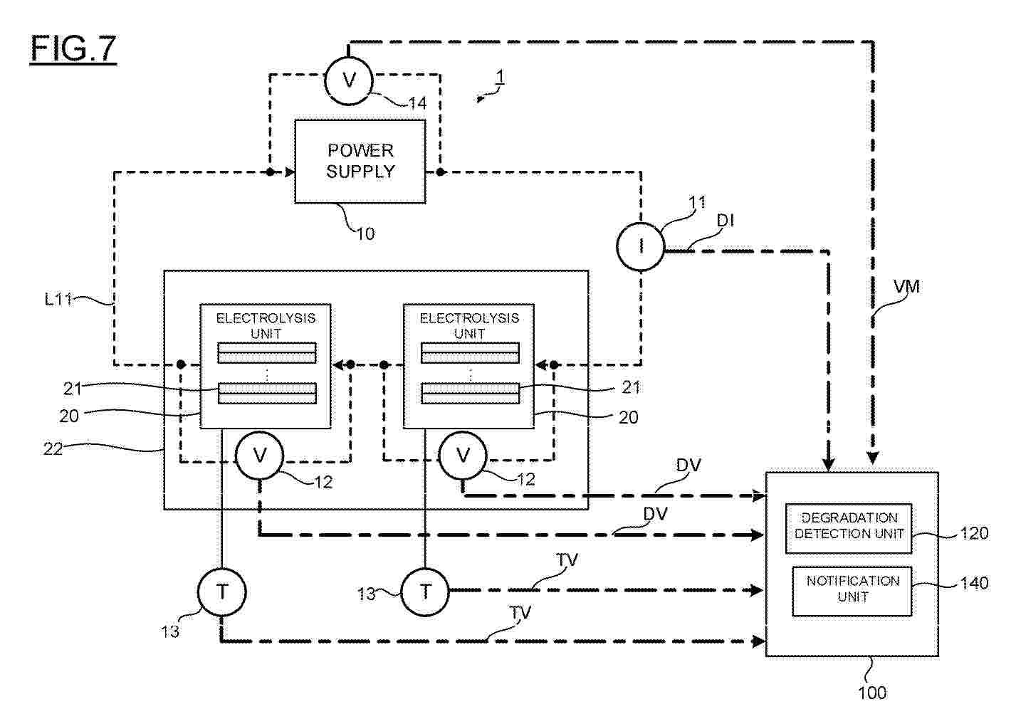
Resumen de: EP4733439A1
0001 A power supply unit supplies a current of a second current value different from a first current value to an electrolysis unit at a first time point from a state of supplying a current of the first current value to the electrolysis unit, and then returns to the state of supplying the current of the first current value at a second time point. A degradation detection unit finds a difference value between a first measured voltage of the electrolysis unit acquired when the current of the first current value is supplied before the first time point and a second measured voltage of the electrolysis unit acquired when the current of the first current value is switched to the current of the second current value at the first time point, and detects the degradation of the electrolysis unit according to the electrolysis unit voltage difference value.
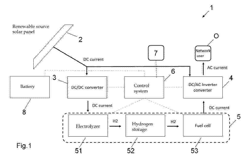
Resumen de: EP4734317A1
The present invention relates to a method (1000-2000) of controlling an electric energy generation plant (1). The plant comprises a unit for generating electric energy from a renewable energy source (2), an electrolyzer (51) for the generation of hydrogen, a battery (8) connected to the electrolyzer (51), at least one converter (3,4) adapted to supply an available power generated by the electric energy generation unit (2) to at least one of a load and the electrolyzer (51), a control system (6) for controlling the plant (1), and input means (7). The input means are adapted to acquire at least one of input information relating to the operation of the plant (1), meteorological information of a region in which the plant (1) is located and information relating to the operation of further plants located in the vicinity of the plant (1).The method comprises that the control system performs the step of: monitoring (1002) the available power, generated by the renewable energy source (2), andwhen the available power falls below a threshold (1011), the method comprises that the control system performs the step of:estimating (1014-1017) a recovery time interval at the end of which the available power will exceed the threshold,determining (1014-1017) whether the battery is able to supply the electrolyzer (51) for said recovery time interval, and in the affirmative case, supplying (1012) the electrolyzer (51) by means of the battery (8).In particular, the step of estimating a recovery tim
Nº publicación: EP4733249A2 29/04/2026
Solicitante:
HONEYWELL INT INC [US]
Honeywell International Inc.
Resumen de: EP4733249A2
A method of treating an at least partially unconsumed hydrogen generator cartridge including water and a metal hydride includes treating the at least partially unconsumed hydrogen generator cartridge to form a treated hydrogen generator cartridge. When subjected to testing conditions the treated hydrogen generator cartridge produces no hydrogen gas or produces hydrogen gas at a lower rate than the at least partially unconsumed hydrogen generator cartridge subjected to the testing conditions. The testing conditions include heating at less than or equal to 300 °C, agitation, exposing the metal hydride to a protic solvent, or a combination thereof.
 BOPI
BOPI
 Sede Electrónica