Si deseas distinguir tus productos, servicios o ambos de los de otra empresa, es posible que necesites una marca o nombre comercial. Descubre qué son, en qué consiste su procedimiento de registro y qué implica.

Información sobre los plazos de presentación de solicitudes de transformación de marcas de la Unión Europea en marca nacional española. Más información


Si tienes un nuevo dispositivo, producto o procedimiento que resuelva un problema técnico o tenga una ventaja práctica, existen distintas formas de protegerlo en España y en otros países. Descubre cómo hacerlo.

¿Tu innovación reside en la estética, la ornamentación o la apariencia de tu producto? Protégela mediante un diseño industrial. Descubre qué derechos confiere el registro y cómo realizar la tramitación.

Las indicaciones geográficas protegen el nombre de un producto originario de una zona geográfica, a la cual le debe una determinada calidad, reputación u otra característica. Descubre qué son, en qué consiste su procedimiento de registro y qué beneficios conceden.

Las patentes publicadas en todo el mundo son una valiosa fuente de información científica, técnica y comercial.

Si eres emprendedor/a o una empresa y quieres potenciar y mejorar la rentabilidad de tu negocio protegiendo de forma adecuada los activos intangibles de tu organización, en este espacio encontrarás lo necesario.


 1450
resultados
1450
resultados
 Última actualización
08/05/2026 [07:34:00]
Última actualización
08/05/2026 [07:34:00]


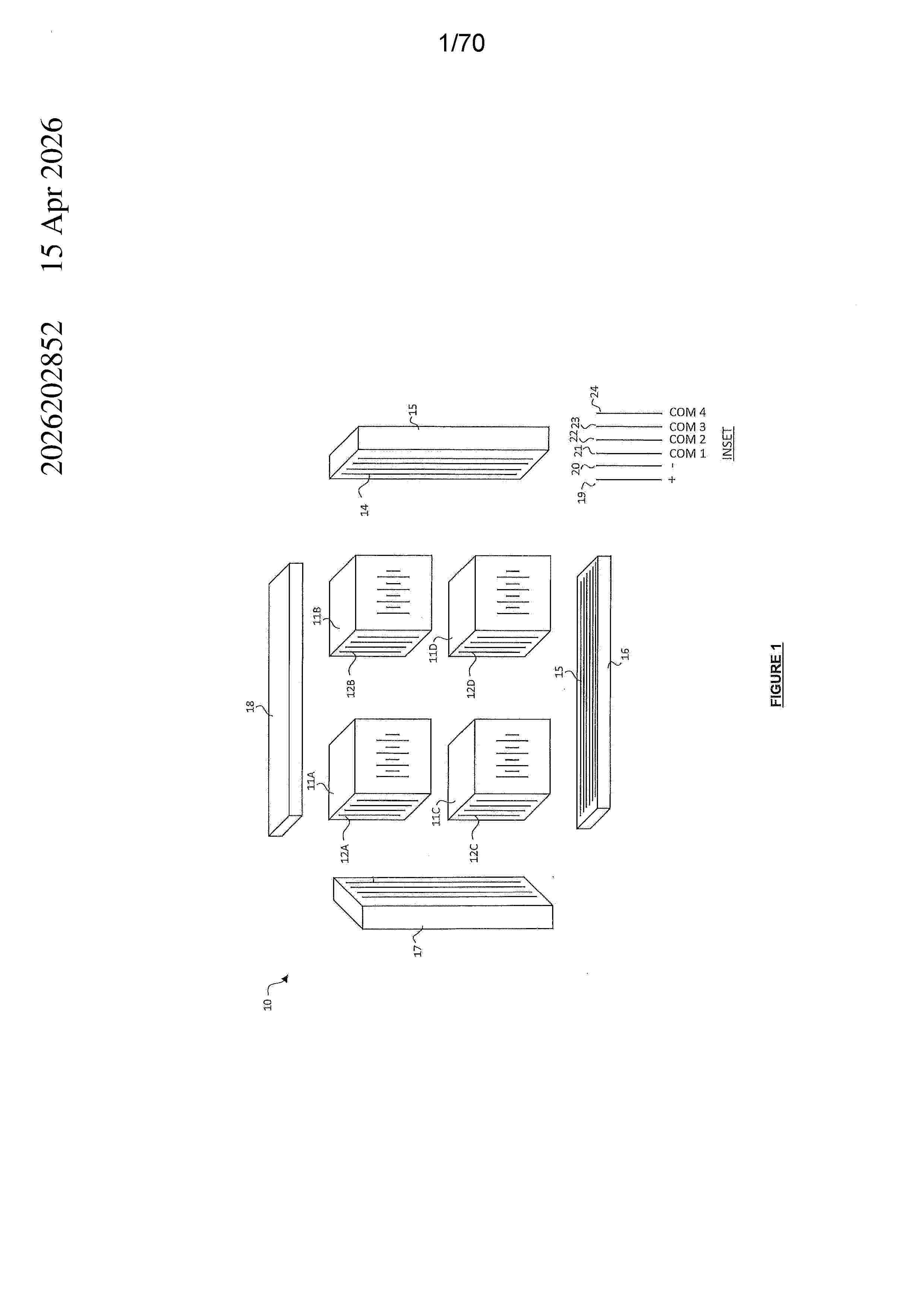
Resumen de: AU2026202852A1
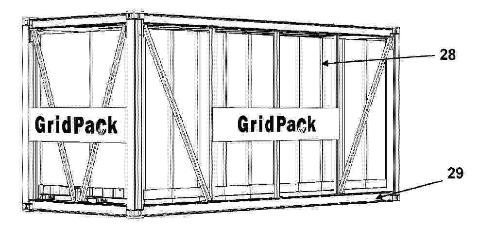
- 115 - A modular, interconnectable housing system; said system comprising modular interconnected housing modules; each housing module defined by one or more wall/frame structures; each housing module containing energy storage components or related energy storage components; said wall/frame structure comprised of a safety engineered system of damage insulating materials designed to reduce risk of externally arising damage to, and external damage arising from, said energy storage components and said energy storage related components. pr p r

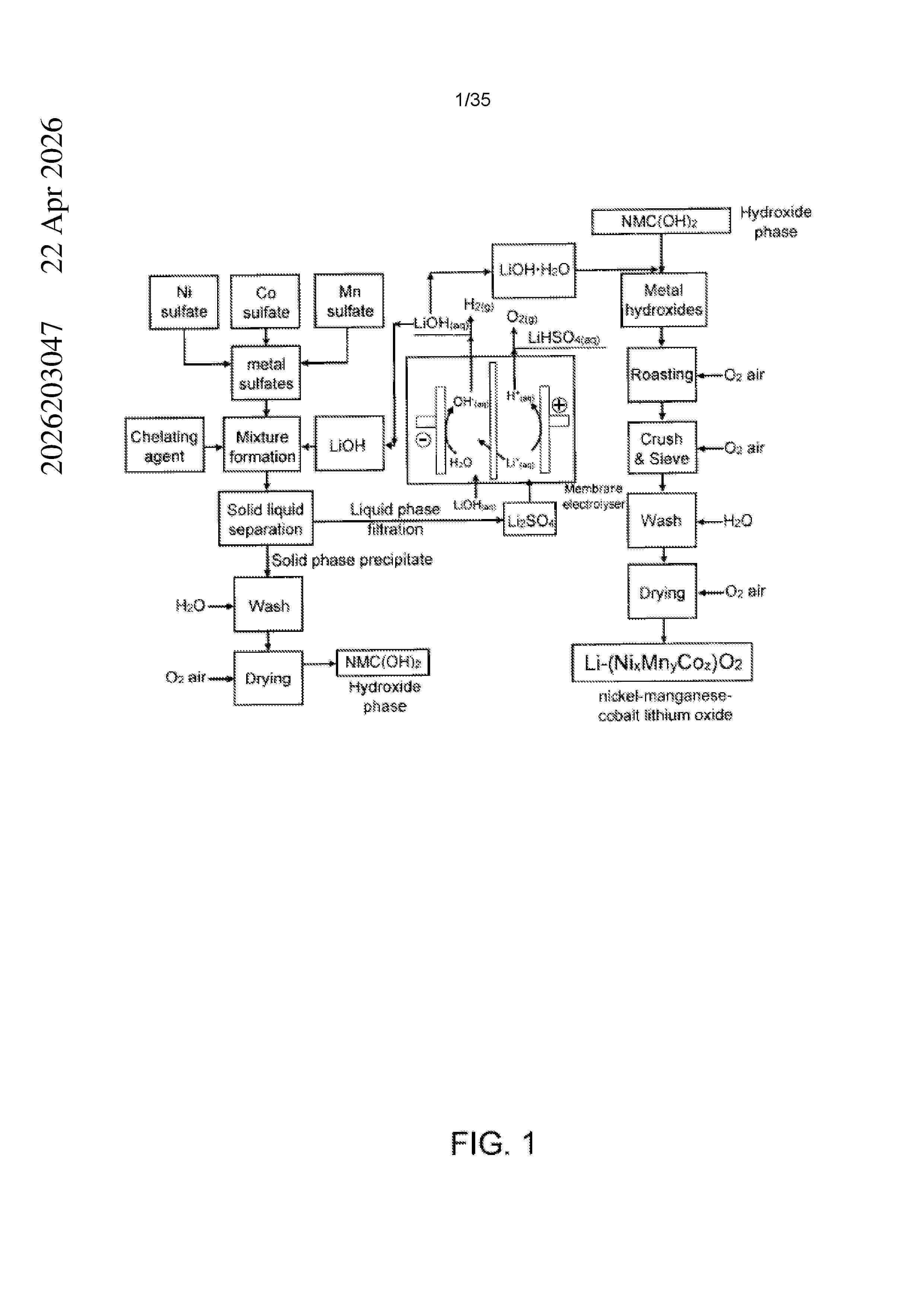
Resumen de: AU2026203047A1
There is provided a process for preparing a metal hydroxide comprising (i) at least one metal chosen from nickel and cobalt and optionally (ii) at least one metal chosen from manganese, lithium and aluminum, said process comprising: reacting a metal sulfate comprising (i) at least one metal chosen from nickel and cobalt and optionally (iii) at least one metal chosen from manganese and aluminum with sodium hydroxide and optionally a chelating agent in order to obtain a solid comprising said metal hydroxide and a liquid comprising sodium sulfate; separating said liquid and said solid from one another to obtain said metal hydroxide; submitting said liquid comprising sodium sulfate to an electromembrane process for converting said sodium sulfate into sodium hydroxide; and reusing said sodium hydroxide obtained by said electromembrane process for reacting with said metal sulfate. pr p r
Resumen de: CN117766736A
The invention discloses a positive electrode active material and a lithium ion battery, the positive electrode active material is lithium iron phosphate coated with a carbon layer, the ID/IG value of the positive electrode active material is 0.75-1.2, and in a Raman spectrum of the positive electrode active material, the peak intensity at the wave number of 1360 cm <-1 > is ID, and the peak intensity at the wave number of 1580 cm <-1 > is IG. The ID/IG value of the positive electrode active material-carbon layer coated lithium iron phosphate is 0.75-1.2, the desolvation rate of Li < + > on an interface of an electrode and an electrolyte is improved, and the desolvation ability is enhanced, so that the conductivity and rate capability of the lithium iron phosphate are improved, and the low-temperature performance of the lithium iron phosphate is improved.
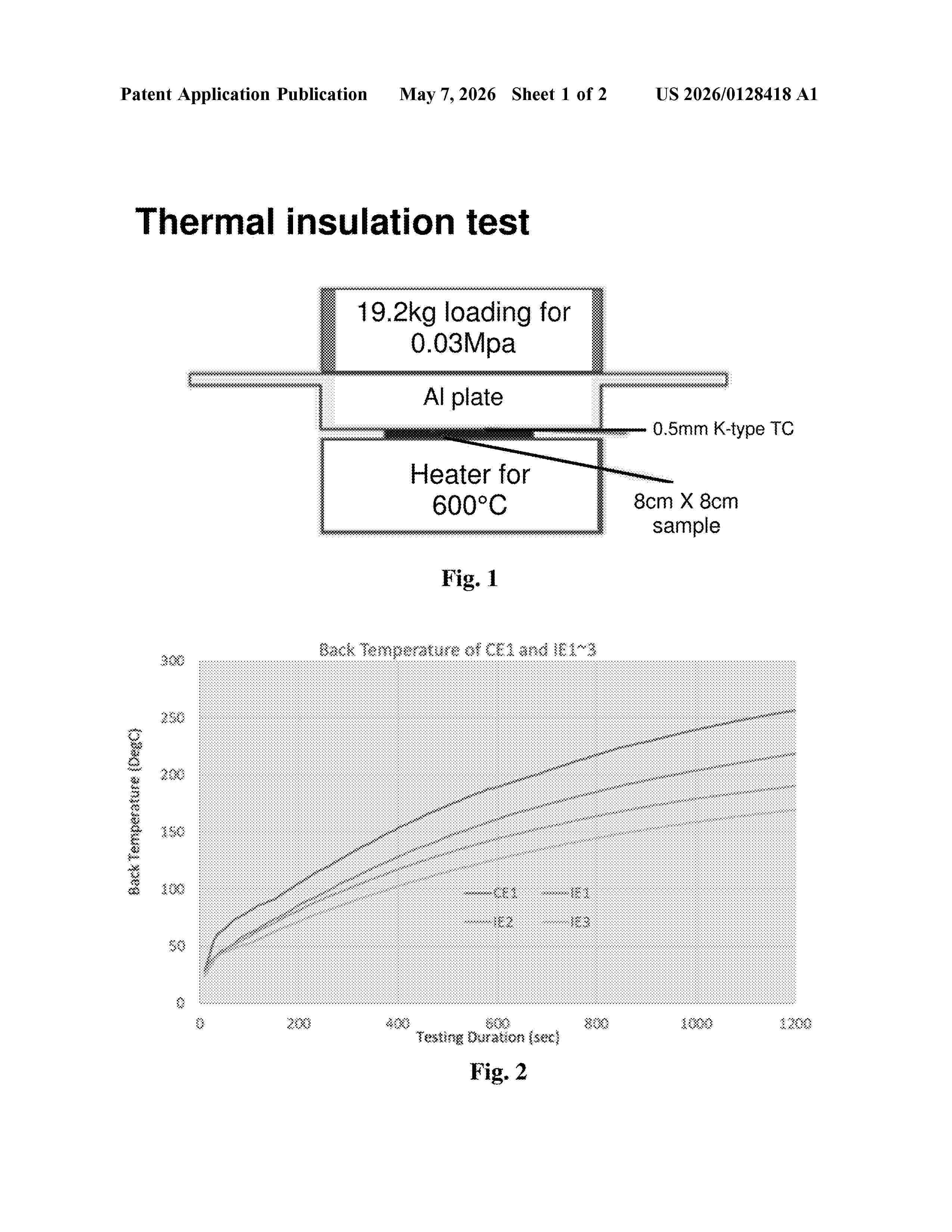
Resumen de: US20260128418A1
The present disclosure relates to a silicone-based fire protection sheet, its production process and battery package having the sheet. The silicone-based fire protection sheet having a structure in which that at least one thermally insulative filler selected from aerogel particles, hollow particles and mesoporous particles are bound in a silicone-based polymeric binder. The amount of the thermally insulative filler ranges from 5 to 40 mass %, and the amount of the silicone-based polymeric binder ranges from 57.5 to 95 mass %, when the total mass of solid content for the silicone-based fire protection sheet is 100 mass %.
Resumen de: AU2024367857A1
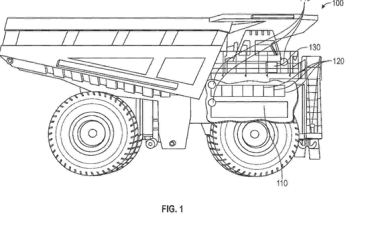
Typically, electric power sources (110), such as batteries and fuel cells, require cooling to temperatures near or below ambient temperature for safe and efficient operation. Traditional cooling systems are not be able or practical to cool the components to the required temperatures, due to the lack of temperature differential between the required cooling temperature and the ambient temperature, which drives the heat transfer. Disclosed embodiments optimize the efficiency of a cooling system based on ambient conditions. In particular, embodiments determine input parameters from one or more sensed parameters, such as ambient temperature and ambient pressure, and utilize these input parameters in a process that maximizes the operation of cooling units (120) in the most efficient mode.
Resumen de: AU2024373251A1
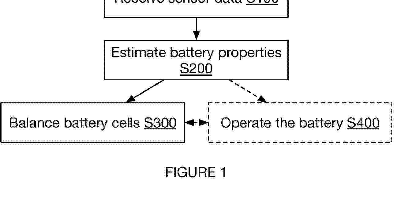
A method can include modeling a state of each battery cell within a battery pack and contemporaneously with discharging a first subset of battery cells of the battery pack either providing a differential drain on the first subset of battery cells such that battery cells of the first subset of battery cells are discharged faster than a second subset of battery cells or charging the second subset of battery cells (e.g., using the first subset of battery cells) where battery cells are identified as in the first subset or the second subset based on the states of the battery cells.
Resumen de: AU2024360191A1
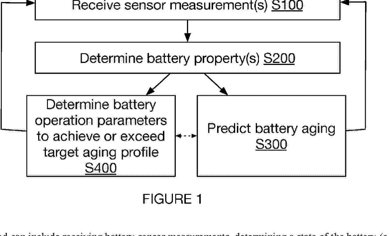
A method can include receiving battery sensor measurements, determining a state of the battery (e.g., SoH, SoC, SoE, SoP, etc. or information correlated therewith such as internal resistance, open circuit voltage, etc.), estimating an aging profile or degradation of the battery for one or more operating conditions, and determining operating conditions for the battery based on the estimated degradation.
Resumen de: AU2024349525A1
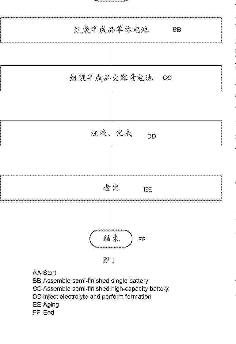
The present invention discloses a manufacturing method for a high-capacity battery, a semi-finished single battery, a battery cell, and a high-capacity battery. The method comprises: manufacturing multiple semi-finished single batteries or battery cells that are not injected with an electrolyte, connecting the semi-finished single batteries or the battery cells in parallel and then placing same in a box body, sealing the box body, and injecting electrolyte into the box body, such that the electrolyte of an inner cavity of each semi-finished single battery or the electrolyte of an inner cavity of each battery cell and the electrolyte in the box body are in one electrolyte system, and then performing a formation operation to complete the manufacturing of the high-capacity battery. Compared with existing high-capacity battery manufacturing methods, processes of liquid injection, sealing, and formation of each single battery are removed, a process of secondary unpacking of each single battery is removed, and high-capacity battery manufacturing efficiency is greatly improved.
Resumen de: DE102025140305A1
Ein aktives Material für ein positive Elektrode umfasst Sekundärpartikel (2). Jedes der Sekundärpartikel (2) umfasst Primärpartikel. Jedes der Primärpartikel umfasst eine Phosphatverbindung vom Olivintyp. Ein Querschnitt des Sekundärpartikels (2) besteht aus einem zentralen Bereich (2a) und einem äußeren Randbereich (2b). Die Beziehung „0,8<_cp2/cp1“ ist erfüllt. „φ1“ steht für die Porosität des zentralen Bereichs (2a). „φ2“ steht für die Porosität des äußeren Randbereichs (2b).
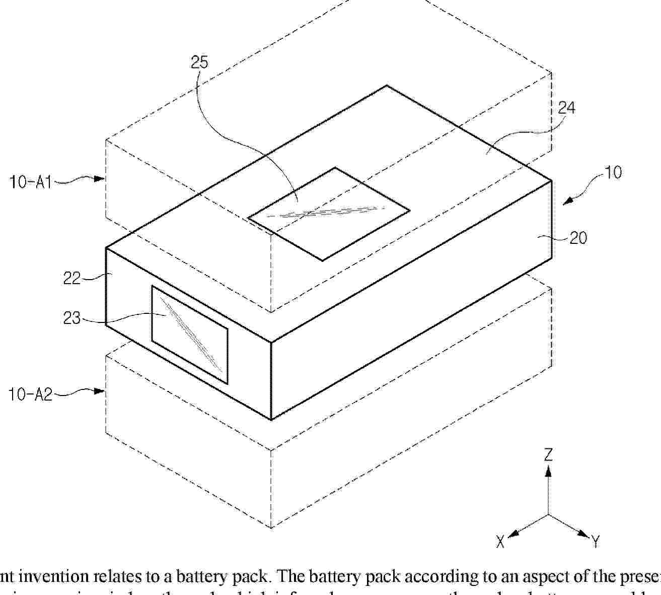
Resumen de: AU2024377924A1
The present invention relates to a battery pack. The battery pack according to an aspect of the present invention includes: a battery pack housing having a main window through which infrared rays may pass through; a battery assembly accommodated in the battery pack housing and composed of at least one battery cell; and a main communication unit capable of receiving infrared rays that have passed through the main window, and may include a slave controller configured to control the battery assembly.
Resumen de: AU2024377433A1
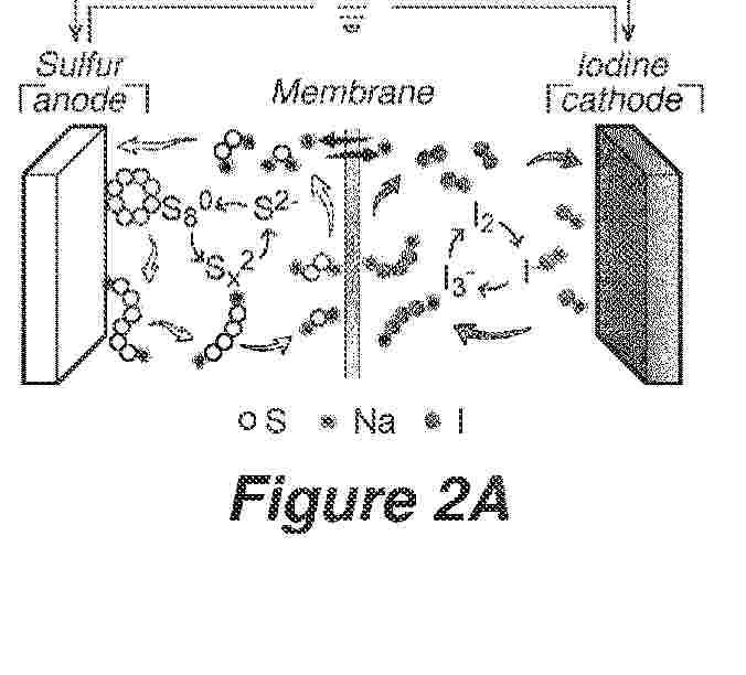
A separator for an electrochemical device is disclosed. The separator comprises a sulfonated polysulfone polymer cation exchange membrane. Also disclosed is an electrochemical device comprising a negative electrode, a positive electrode, the separator separating the negative electrode and the positive electrode, and an electrolyte solution.
Resumen de: DE102024132316A1
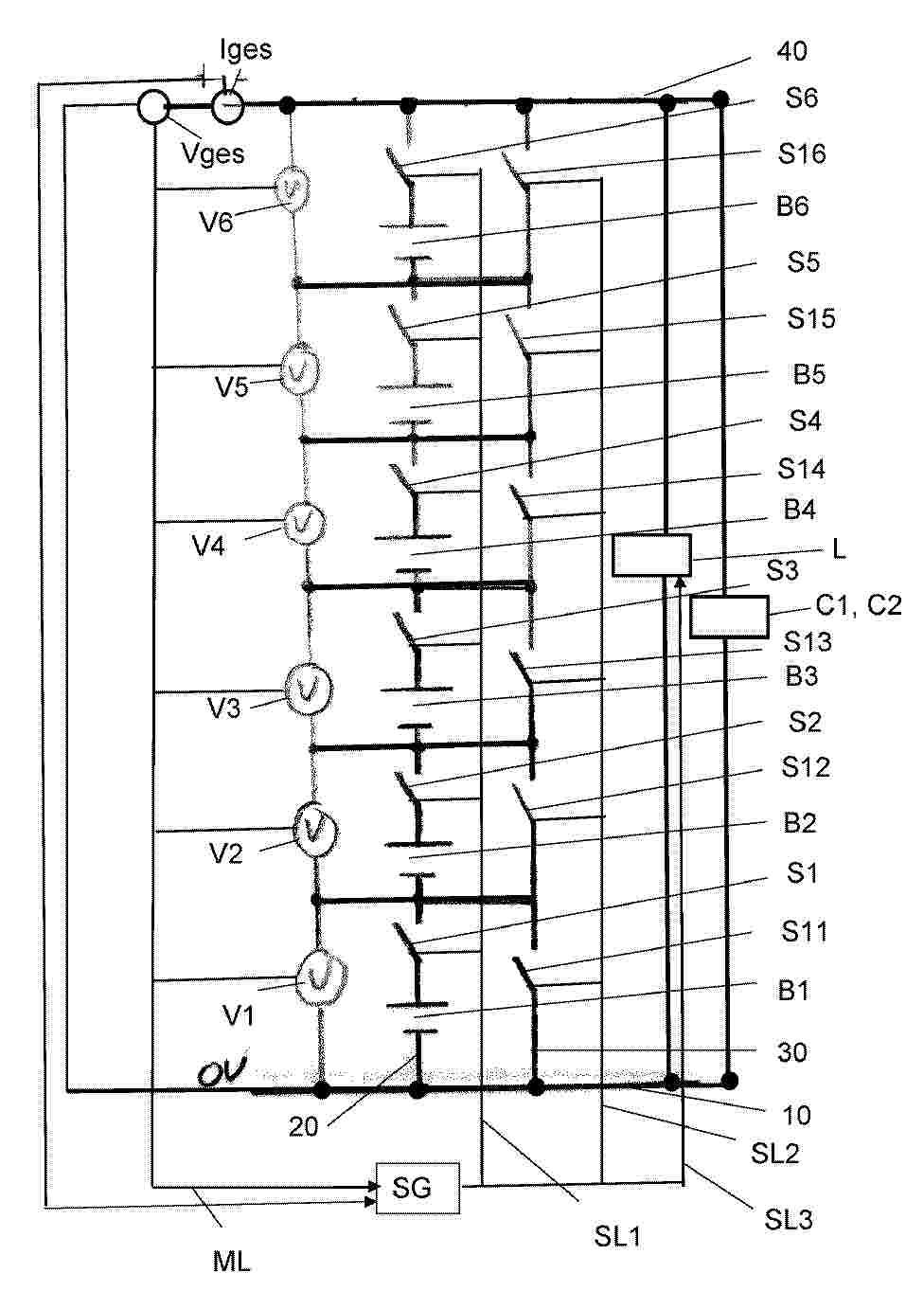
Die Erfindung betrifft eine Vorrichtung zur Spannungsversorgung wenigstens eines Verbrauchers (C1, C2) mit einem elektrischen Nennspannungsbereich (Vn) durch wenigstens eine Reihenschaltung (20) mehrerer in Reihe geschaltete Batteriezellen (B1....B6). Die Erfindung sieht vor, dass alle in Reihe geschalteten Batteriezellen (B1....B6) einer Reihenschaltung (20) in voll geladenem Zustand in Summe eine Gesamtspannung (Vges) erzeugen, die oberhalb des Nennspannungsbereichs (Vn) des wenigstens eines Verbrauchers (C1, C2) liegt und dass durch wenigstens eine Bypassleitung (30) und mehrere Schaltelemente (S1.... S6; S11....... S16) einzelne Batteriezellen (B1....B6) oder Gruppen von Batteriezellen (B1....B6) in die Reihenschaltung (20) einschaltbar oder aus dieser herausschaltbar sind, um die Gesamtspannung (Vges) der Reihenschaltung (20) in den Nennspannungsbereich (Vn) des wenigstens eines Verbrauchers (C1, C2) zu bringen. Die Erfindung betrifft weiterhin ein Verfahren zur Steuerung einer elektrischen Gesamtspannung (Vges) einer Reihenschaltung (20) in Reihe geschaltete Batteriezellen (B1....B6) in den Nennspannungsbereich (Vn) wenigstens eines Verbrauchers (C1, C2) und ein Verfahren zur Steuerung einer Ladespannung von in wenigstens einer Reihenschaltung (20) in Reihe geschalteten Batteriezellen (B1....B6).
Resumen de: DE102024004603A1
Gegenstand der Erfindung ist eine elektrochemische Natrium-Metallhalogenid-Sekundärzelle (0) umfassend ein Gehäuse (1) und einem langfristig mechanisch und/oder chemisch widerstandsfähigen und wechselnden thermischen Belastungen standhaltenden Stromabnehmer mit einem Hohlraum (14) mit einem Reservoir zur Aufnahme des Sekundärelektrolyten sowie ein Batteriemodul, System umfassend das Batteriemodul, als auch ein Energiespeichersystem als auch dessen Verwendung.
Resumen de: DE102025111770A1
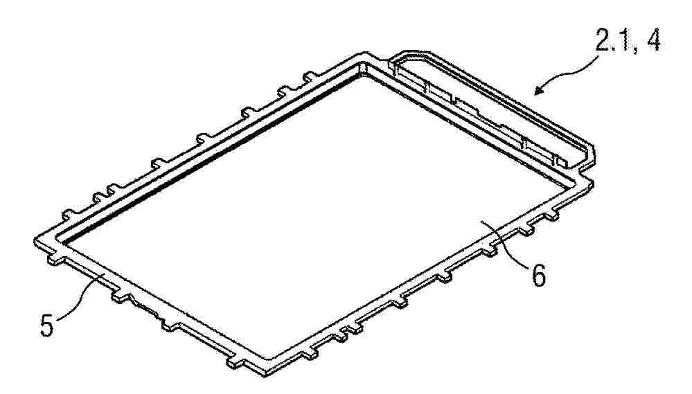
Die Erfindung betrifft ein Gehäuse (2) für einen elektrischen Energiespeicher (1), aufweisend eine Temperiervorrichtung (4) und einen Aufnahmebereich zur Anordnung elektrisch verschalteter Einzelzellen (3), wobei die Temperiervorrichtung (4) zur Temperierung der Einzelzellen (3) ausgebildet ist. Erfindungsgemäß ist vorgesehen, dass die Temperiervorrichtung (4) eine von einem Temperiermedium durchströmbare mediendichte Kanalstruktur (K) aufweist, die mittels mediendichter Temperierkanäle gebildet ist, und die Temperiervorrichtung (4) plattenförmig ausgebildet ist und eine Gehäusewand (2.1) bildet. Weiterhin betrifft die Erfindung einen elektrischen Energiespeicher (1).
Resumen de: DE102025137028A1
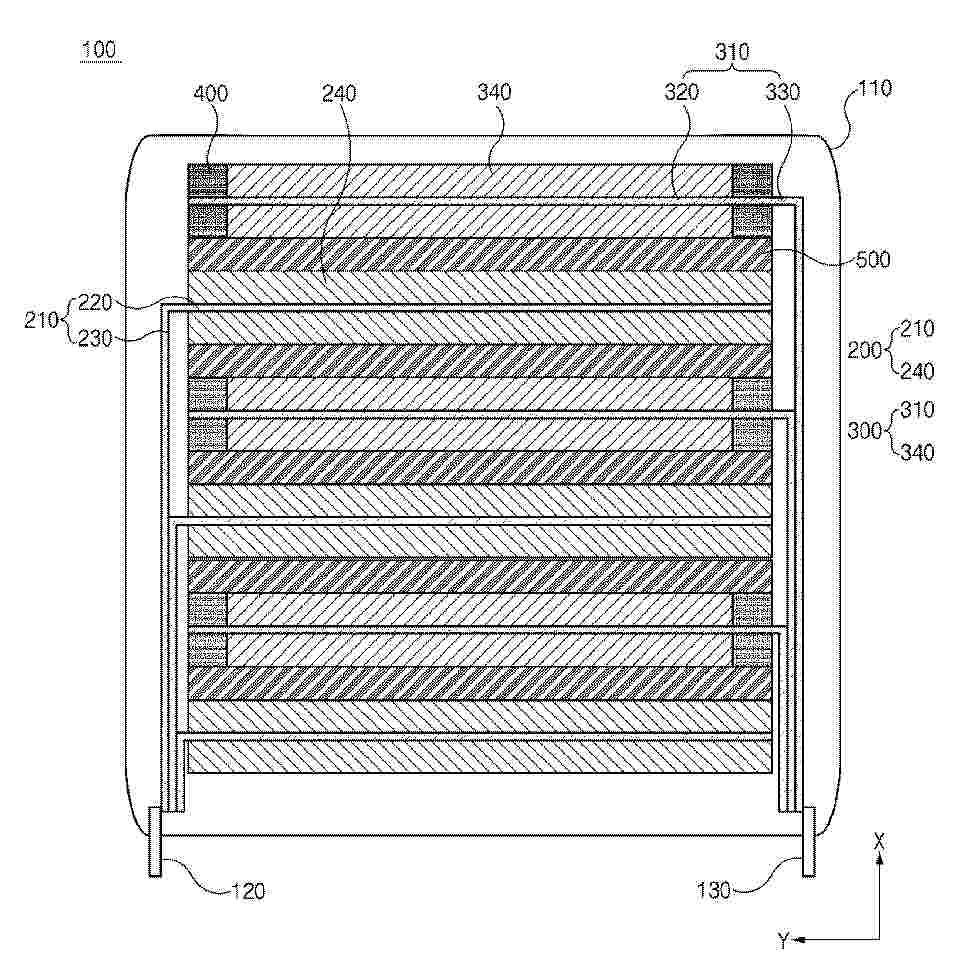
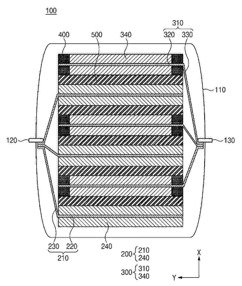
Eine Festkörperbatterie (100) kann aufwiesen: eine Mehrzahl von ersten Elektroden (200), wobei jede erste Elektrode (200) einen ersten Elektrodenstromkollektor (210) mit einem ersten Elektrodenkörper (220) und einer ersten Elektrodenfahne (230) und ein erstes Elektrodenaktivmaterial (240), welches an dem ersten Elektrodenstromkollektor (210) angeordnet ist, aufweist, eine Mehrzahl von zweiten Elektroden (300), welche eine Polarität, welche sich von einer Polarität der Mehrzahl von ersten Elektroden (200) unterscheidet, aufweisen und abwechselnd mit der Mehrzahl von ersten Elektroden (200) in einer ersten Richtung gestapelt sind, wobei jede zweite Elektrode (300) einen zweiten Elektrodenstromkollektor (310) mit einem zweiten Elektrodenkörper (320) und einer zweiten Elektrodenfahne (330) und ein zweites Elektrodenaktivmaterial (340), welches an dem zweiten Elektrodenstromkollektor (310) angeordnet ist, aufweist, und einen Festelektrolyten (500), welcher zwischen der ersten Elektrode (200) und der zweiten Elektrode (300) angeordnet ist.
Resumen de: DE102024210631A1
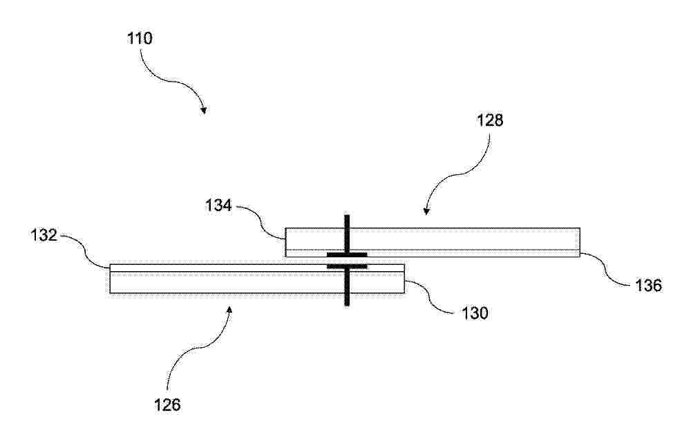
Ein Batteriemanagementsystem (110) wird offenbart. Das Batteriemanagementsystem (110) umfasst eine Vielzahl von Leiterplatten (126, 128). Eine erste Leiterplatte (126) und eine zweite Leiterplatte (128) sind galvanisch voneinander isoliert und zum Übertragen eines elektronischen Signals über eine nichtleitende elektronische Kopplung zwischen einander angeordnet. Ferner wird ein Verfahren zum Anordnen und Betreiben des Batteriemanagementsystems (110) offenbart.
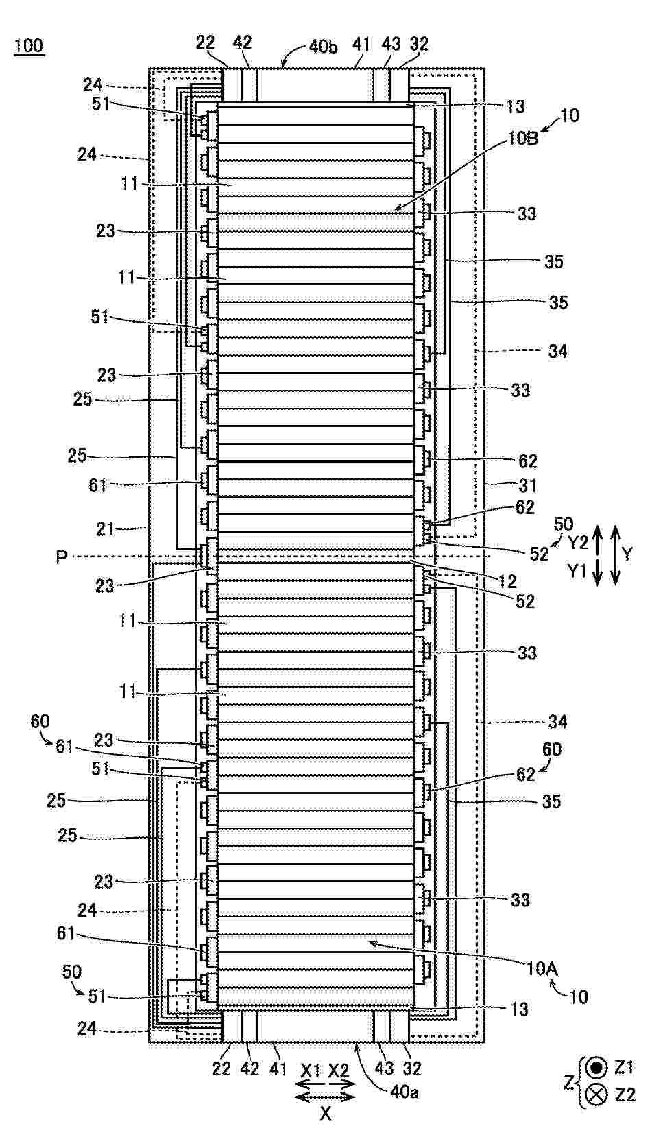
Resumen de: DE102025144753A1
Ein Sammelschienenmodul (30) umfasst eine Vielzahl von Sammelschienen (23), die auf einer X1-Seite bezüglich eines Modulzentrums (3) angeordnet sind, und eine Vielzahl von Sammelschienen (33), die auf einer X2-Seite bezüglich des Modulzentrums (3) angeordnet sind. Eine Temperaturerfassungseinheit (50) umfasst einen Temperatursensor (51), der auf der X1 Seite bezüglich des Modulzentrums (3) angeordnet ist, und einen Temperatursensor (52), der auf der X2 Seite bezüglich des Modulzentrums (3) angeordnet ist. Ein Erfassungsverbinder (42) ist elektrisch mit dem Temperatursensor (51) verbunden und ist auf der X1 Seite bezüglich eines Modulhauptkörpers (41) angeordnet. Ein Erfassungsverbinder (43) ist elektrisch mit dem Temperatursensor (52) verbunden und ist auf der X2 Seite bezüglich des Modulhauptkörpers (41) angeordnet.
Resumen de: DE102024132060A1
Beschrieben wird ein Kühlhohlprofil (10) für eine Kühleinrichtung, insbesondere für eine Kühleinrichtung zur Batteriekühlung eines Kraftfahrzeugs, mit zwei sich gegenüber angeordneten ersten Wandabschnitten (12) aus einem Metall oder einer Metalllegierung; zwei sich gegenüber angeordneten zweiten Wandabschnitten (14) aus einem Kunststoff; wobei die ersten Wandabschnitte (12) und die zweiten Wandabschnitte (14) entlang eines Umfangs des Kühlhohlprofils (10) alternierend angeordnet sind, wobei die zweiten Wandabschnitte (14) mittels Extrusion materialschlüssig oder/und formschlüssig mit den ersten Wandabschnitten (12) verbunden sind, derart, dass die ersten Wandabschnitte (12) und die zweiten Wandabschnitte (14) einen kanalartigen Innenraum (16) umgeben. Ferner wird ein Verfahren zur Herstellung eines solchen Kühlhohlprofils (10) beschrieben. Eine Kühleinrichtung eines Kraftfahrzeugs kann wenigstens ein solches Kühlhohlprofil (10) aufweisen.
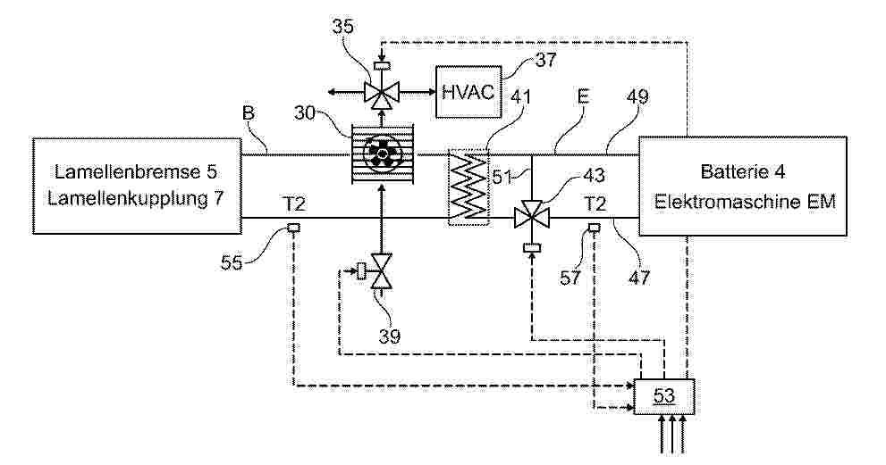
Resumen de: DE102024131983A1
Die Erfindung betrifft ein Thermomanagementsystem in einem elektrisch betriebenen Fahrzeug, mit zumindest einer nasslaufenden Lamellenbremse und/oder -kupplung (5, 7), mittels der eine Bremsbetätigung, etwa für eine Fahrzeugbremsung, durchführbar ist, wobei die Lamellenbremse und/oder - kupplung (5, 7) in einem Bremskreislauf (B) geschaltet ist, in dem Kühlmittel umwälzbar ist, um die beim Bremsvorgang erzeugte Abwärme abzuführen. Erfindungsgemäß ist zum Abführen der Abwärme der Bremskühlkreislauf (B) über einen Luft/Flüssigkeitswärmetauscher (30) mit einem Luftkanal (31) thermisch gekoppelt, der von einem Abluftstrom (I) durchströmbar ist.
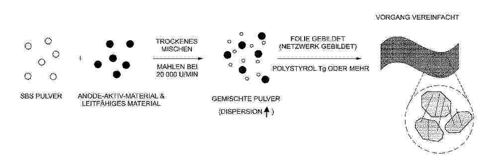
Resumen de: DE102025119516A1
Verfahren zum Herstellen einer freistehenden Folie für eine Anode einer Lithium-Sekundärbatterie und freistehende Folie für eine Anode einer Lithium-Sekundärbatterie, die durch dasselbe hergestellt worden ist, wobei das Verfahren aufweist: Erhalten von Pulvern zum Bilden der Anode mittels Mischens und Mahlens einer Zusammensetzung zum Bilden der Anode, die ein Anode-Aktiv-Material, ein leitfähiges Material und ein Bindemittel enthält (S1), und Bilden einer Anode-Aktiv-Material-Schicht durch einen Folie-Bilden-Vorgang unter Verwendung der Pulver zum Bilden der Anode (S2). Das Bindemittel weist ein Triblock-Copolymer auf, das umfasst: einen weichen Block, der eine aliphatische oder cycloaliphatische Dien-Monomer-Einheit aufweist und bei Raumtemperatur eine gummiartige Phase zeigt, einen ersten harten Block, der mit einem Ende des weichen Blocks verbunden ist, eine ethylenisch ungesättigte Monomereinheit aufweist, die einen aromatischen Ring enthält, und bei Raumtemperatur eine Glasphase zeigt, und einen zweiten harten Block, der mit einem anderen Ende des weichen Blocks verbunden ist, eine ethylenisch ungesättigte Monomereinheit aufweist, die einen aromatischen Ring enthält, und bei Raumtemperatur die Glasphase zeigt, und ein durchschnittlicher Teilchendurchmesser (D50) des Bindemittels, das in den Pulvern zum Bilden der Anode enthalten ist, kleiner ist als ein durchschnittlicher Teilchendurchmesser (D50) des Bindemittels, das in der Zusammensetzung zum Bilden der Ano
Resumen de: DE102024132514A1
Die Erfindung betrifft ein Verfahren zur Reparatur eines über einen Abschnitt seiner Länge zerstörten Zellkontaktierungssystems (16) einer Batterie (12). Bei dem Verfahren wird in einem ersten Schritt ein Bild von einem zu zerstörenden Abschnitt (32) des Zellkontaktierungssystems (18) mittels einer Detektionseinrichtung (30) aufgenommen. In einem zweiten Schritt wird ein Ersatzabschnitt (26) mit wenigstens einer Leiterbahn (28) auf Basis des aufgenommen Bildes erzeugt. Und in einem dritten Schritt wird die wenigstens eine Leiterbahn (28) des Ersatzabschnittes (36) mit wenigstens einer Leiterbahn (28) des Zellkontaktierungssystems (18) verbunden. Des Weiteren betrifft die Erfindung eine Batterie (12) sowie ein Fahrzeug.
Resumen de: DE102025137030A1
Eine Festkörperbatterie weist auf: eine Mehrzahl von ersten Elektroden 200, wobei jede erste Elektrode 200 einen ersten Elektrodenstromkollektor 210 mit einem ersten Elektrodenkörper 220 und einer ersten Elektrodenlasche 230 sowie ein auf dem ersten Elektrodenstromkollektor 210 angeordnetes erstes Elektrodenaktivmaterial 240 aufweist, eine Mehrzahl von zweiten Elektroden 300, die eine von der Polarität der Mehrzahl von ersten Elektroden 200 verschiedene Polarität aufweisen und abwechselnd mit der Mehrzahl von ersten Elektroden 200 in einer ersten Richtung gestapelt sind, wobei jede zweite Elektrode 300 einen zweiten Elektrodenstromkollektor 310 mit einem zweiten Elektrodenkörper 320 und einer zweiten Elektrodenlasche 330 sowie ein auf dem zweiten Elektrodenstromkollektor 310 angeordnetes zweites Elektrodenaktivmaterial 340 aufweist, und einen Festelektrolyten 500, der zwischen jeder ersten Elektrode 200 und jeder zweiten Elektrode 300 angeordnet ist.
Resumen de: DE102025138157A1
Ein Batteriepack umfasst eine Batteriezelle mit einem Sicherheitsventil, das sich öffnet, wenn ein Innendruck zunimmt, und Gas nach außen abgibt, einen Auslassdurchlass, durch den Gas strömt, welches von dem Sicherheitsventil freigesetzt wird, ein Wärmeisolationselement, welches bereitgestellt ist, um das Sicherheitsventil abzudecken, und ein Halteelement, welches das Wärmeisolationselement hält, wobei ein Aufnahmeabschnitt bei einem Wandabschnitt des Auslassdurchlasses an einer Position bereitgestellt ist, die dem Wärmeisolationselement zugewandt ist, und das Wärmeisolationselement eine thermische Isolation zwischen dem Auslassdurchlass und der Batteriezelle bereitstellt, wenn das Sicherheitsventil nicht geöffnet ist, und durch das von dem Sicherheitsventil freigesetzte Gas von dem Halteelement getrennt und in dem Aufnahmeabschnitt aufgenommen ist, wenn das Sicherheitsventil geöffnet ist, um eine thermische Isolation zwischen dem von dem Sicherheitsventil freigesetzten Gas und dem Wandabschnitt des Auslassdurchlasses bereitzustellen.
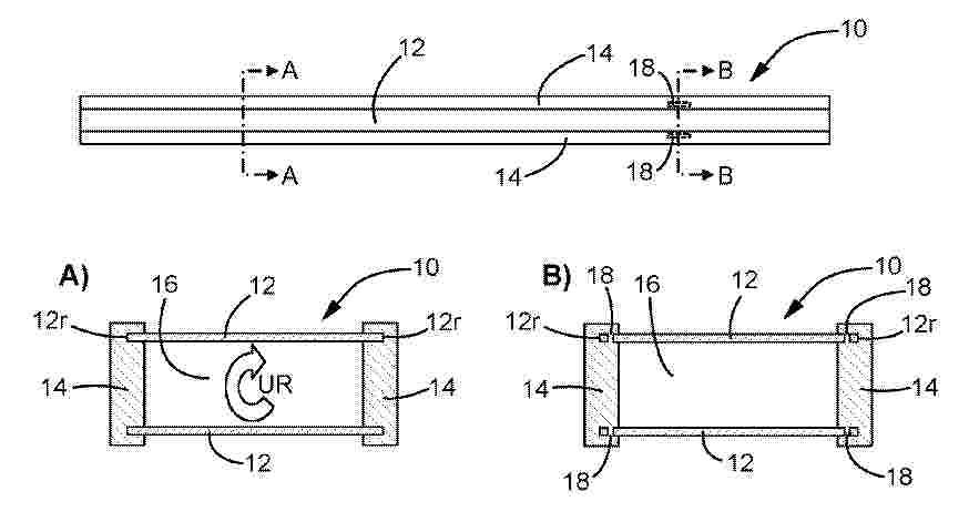
Resumen de: DE102025135749A1
Die vorliegende Erfindung betrifft eine zylindrische Batteriezelle (12) für ein Batteriemodul (10) eines Kraftfahrzeugs, umfassend ein Zellengehäuse (14), das zumindest teilweise einen Aufnahmeraum (16) definiert, und eine im Aufnahmeraum (16) angeordnete Schichtstruktur (20), die innerhalb der Schichtstruktur (20) eine Vielzahl von Schichten (18) umfasst, die in axialer Richtung (24) der zylindrischen Batteriezelle (12) nebeneinander angeordnet sind, wobei die Schichten (18) jeweils eine Kathodenschicht (26), eine Festkörperelektrolytschicht (28) und eine weitere Schicht (30) umfassen, und wobei die jeweilige Festkörperelektrolytschicht (28) in axialer Richtung (24) der zylindrischen Batteriezelle (12) zwischen der jeweiligen Kathodenschicht (26) und der jeweiligen weiteren Schicht (30) angeordnet ist.
Nº publicación: DE102024132442A1 07/05/2026
Solicitante:
BAYERISCHE MOTOREN WERKE AG [DE]
Bayerische Motoren Werke Aktiengesellschaft
Resumen de: DE102024132442A1
Bei einem Verfahren zur Trennung einer Aktivmaterialschicht von einer Kathodenelektrodenfolie wird eine zerkleinerte Kathodenelektrodenfolie bereitgestellt, wobei die zerkleinerte Kathodenelektrodenfolie einen Binder und eine Aktivmaterialschicht aufweist. Die zerkleinerte Kathodenelektrodenfolie wird in einem Plasmaofen mittels eines Plasmagases behandelt zum Zersetzen des Binders der zerkleinerten Kathodenelektrodenfolie. Die zerkleinerte Kathodenelektrodenfolie wird während der Behandlung mittels des Plasmagases zusätzlich mechanisch bearbeitet zur Abtrennung der Aktivmaterialschicht von der zerkleinerten Kathodenelektrodenfolie.
 BOPI
BOPI
 Sede Electrónica