Si deseas distinguir tus productos, servicios o ambos de los de otra empresa, es posible que necesites una marca o nombre comercial. Descubre qué son, en qué consiste su procedimiento de registro y qué implica.

Información sobre los plazos de presentación de solicitudes de transformación de marcas de la Unión Europea en marca nacional española. Más información


Si tienes un nuevo dispositivo, producto o procedimiento que resuelva un problema técnico o tenga una ventaja práctica, existen distintas formas de protegerlo en España y en otros países. Descubre cómo hacerlo.

¿Tu innovación reside en la estética, la ornamentación o la apariencia de tu producto? Protégela mediante un diseño industrial. Descubre qué derechos confiere el registro y cómo realizar la tramitación.

Las indicaciones geográficas protegen el nombre de un producto originario de una zona geográfica, a la cual le debe una determinada calidad, reputación u otra característica. Descubre qué son, en qué consiste su procedimiento de registro y qué beneficios conceden.

Las patentes publicadas en todo el mundo son una valiosa fuente de información científica, técnica y comercial.

Si eres emprendedor/a o una empresa y quieres potenciar y mejorar la rentabilidad de tu negocio protegiendo de forma adecuada los activos intangibles de tu organización, en este espacio encontrarás lo necesario.


 128
resultados
128
resultados
 Última actualización
01/07/2026 [12:46:00]
Última actualización
01/07/2026 [12:46:00]


Resumen de: WO2026132131A1
A support structure suitable for a floating offshore wind turbine comprises a floater and upright tension legs extending from respective leg anchors to the floater The legs correspond to side edges of a prism, with upright side faces of the prism being defined between neighbouring legs. Additionally, inclined tensile braces extend diagonally across the side faces from individual or shared brace anchors to the floater. Each tension leg lies in a plane that extends between a pair of the braces, the braces of the pair extending across respective adjoining side faces and converging downwardly toward that plane. Braces of different pairs cross each other with mutually opposed inclination as they extend across the side faces.

Resumen de: WO2026135204A1
A floating structure is disclosed. A floating structure according to an embodiment of the present invention comprises: a center column to which a tower including an offshore wind power nacelle is connected; pontoons each having a plurality of sides and connected to the center column; outer columns each arranged between the plurality of sides of the pontoons; and connection members connecting the pontoons and the center column, wherein the pontoon comprises concrete portions, in the plurality of sides, connected to the outer columns and forming both end portions of the plurality of sides, and a steel material portion disposed between the concrete portions at both end portions of the plurality of sides and connecting the concrete portions arranged at the both end portions of the plurality of sides. The connection member is coupled to the steel material portion such that the pontoons can be connected to the center column.
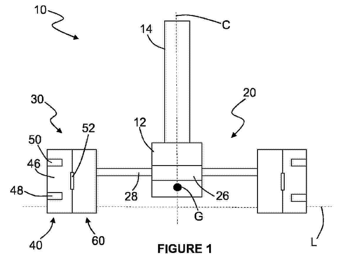
Resumen de: WO2026130731A1
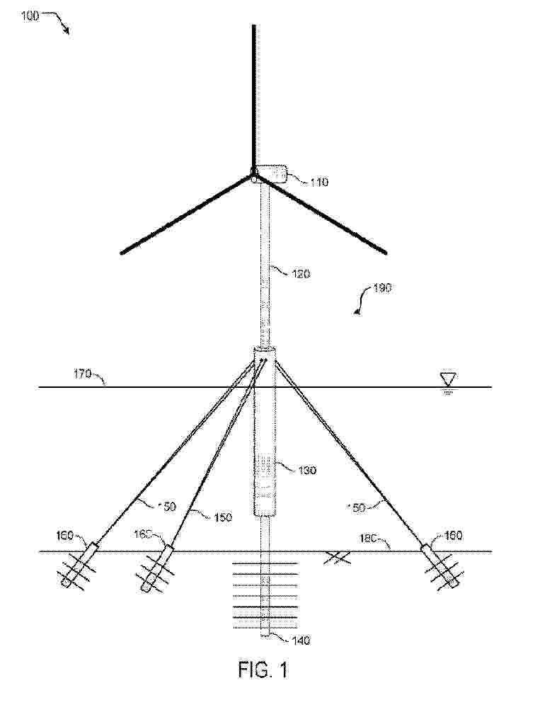
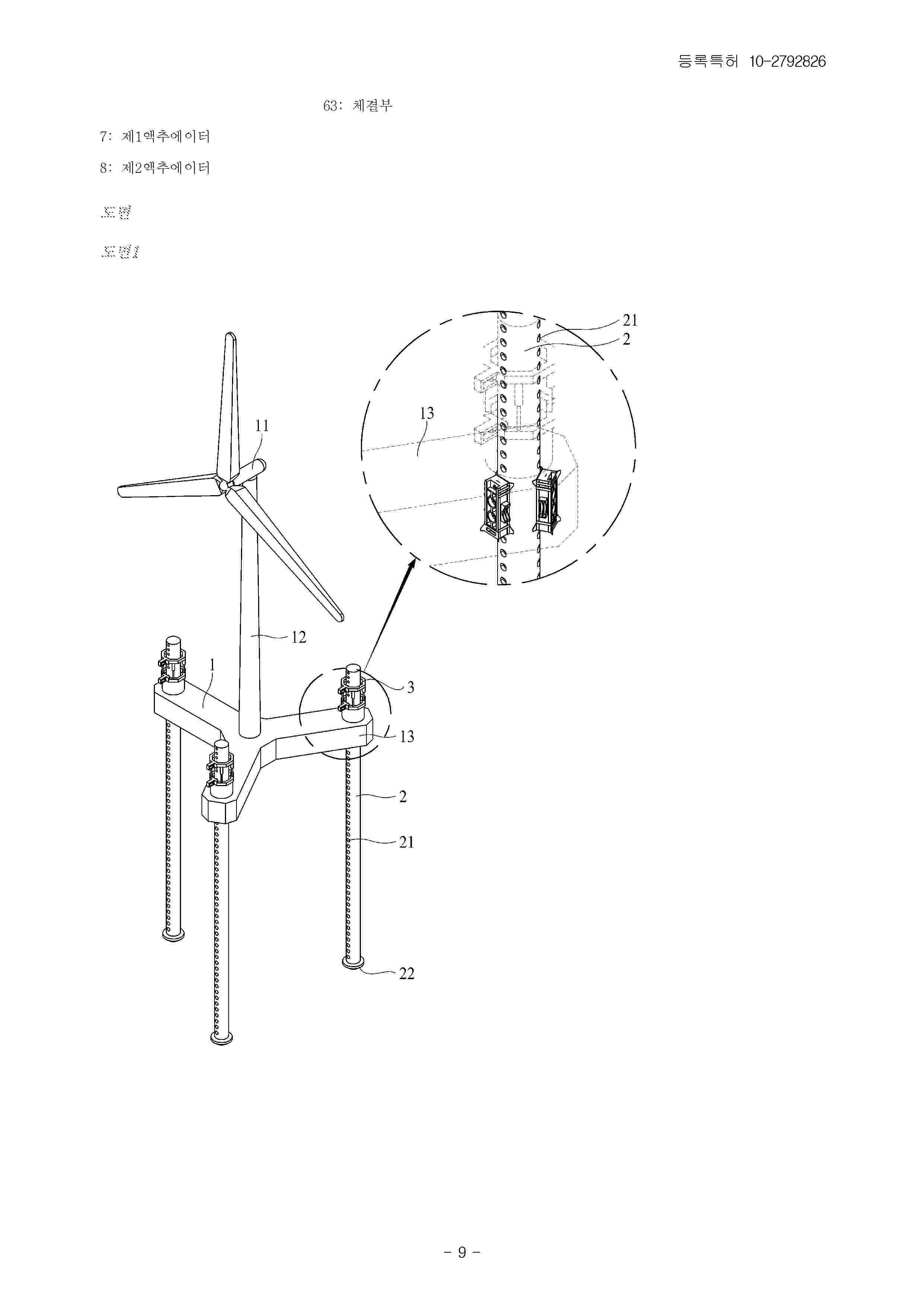
The invention relates to a floating platform (10) for supporting a tower (1) with a wind turbine (2) for harnessing wind energy. The floating platform (10) comprises a floating element (11) and an adaptive mooring system for automatically achieving a substantially vertical alignment of the tower (1) at different wind speeds. The adaptive supporting system comprises a mooring rope (21) coupled to the floating platform (10) and configured for fixing said mooring rope (21) via a ground anchor (50) to the ground (101), a cantilever beam (25) with a proximal end (24) attached to the floating platform (10) and a distal end (26), the mooring rope (21) being coupled to the distal end (26), and a weight (22) coupled to said mooring rope (21) and being positioned below the cantilever beam (25), wherein a variable position of the weight (22) with respect to the cantilever beam (25) supports a compensation of forces from the wind acting on the wind turbine (2) such that the orientation of the tower (1) is substantially vertical.
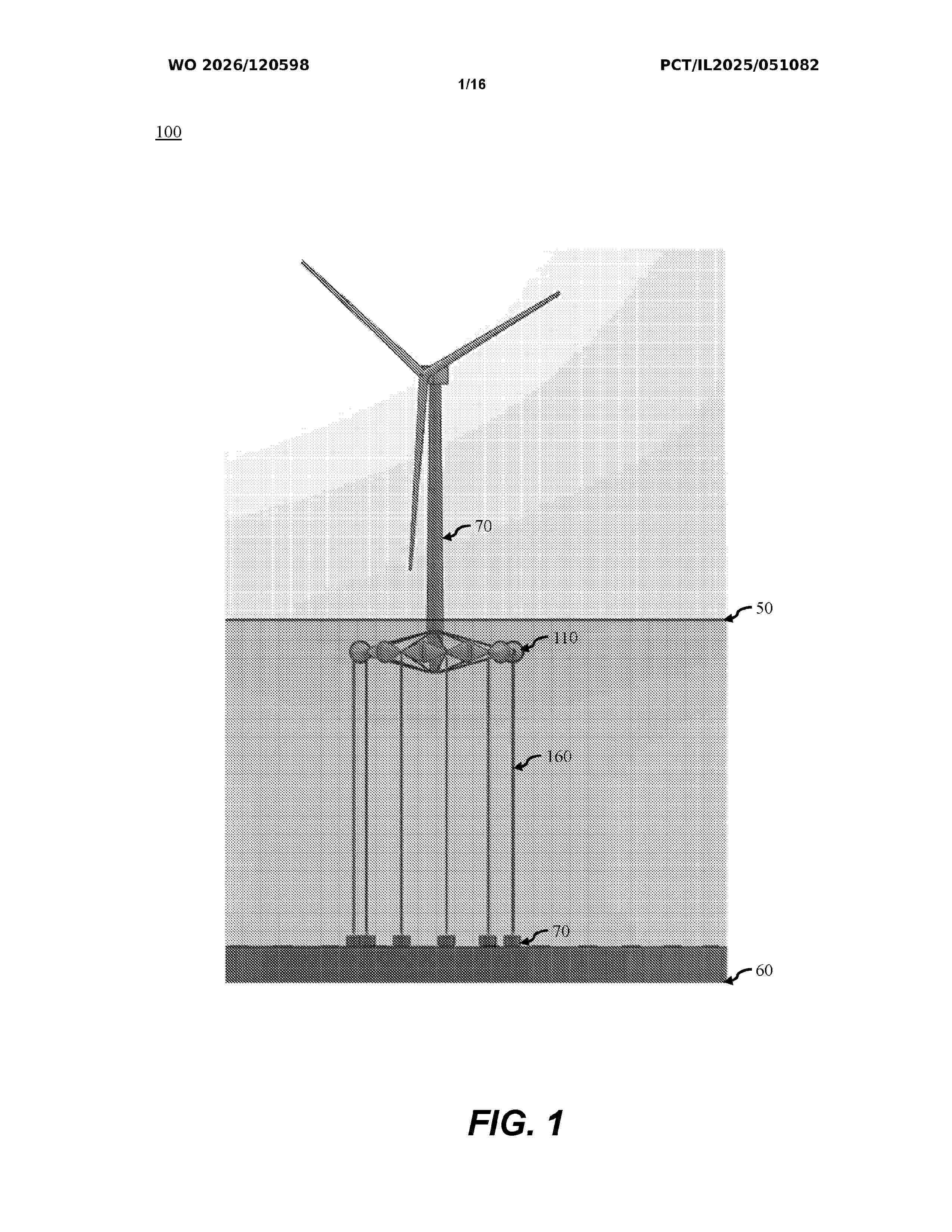
Resumen de: WO2026120598A1
A floating substructure for supporting an offshore wind turbine includes a plurality of buoys arranged in a ring configuration and interconnected by articulating joints. A central column is positioned within the ring and is configured to receive and support a distal portion of a turbine tower. A plurality of first slings extends from a proximal region of the central column to corresponding articulating joints, and a plurality of second slings extends from a distal region of the central column to corresponding articulating joints. A plurality of anchors is positioned to anchor the substructure, and a plurality of third slings connects the anchors to the respective articulating joints. The arrangement of buoys, articulating joints, and sling systems provides a tension-based support structure suitable for deep-water offshore wind applications.
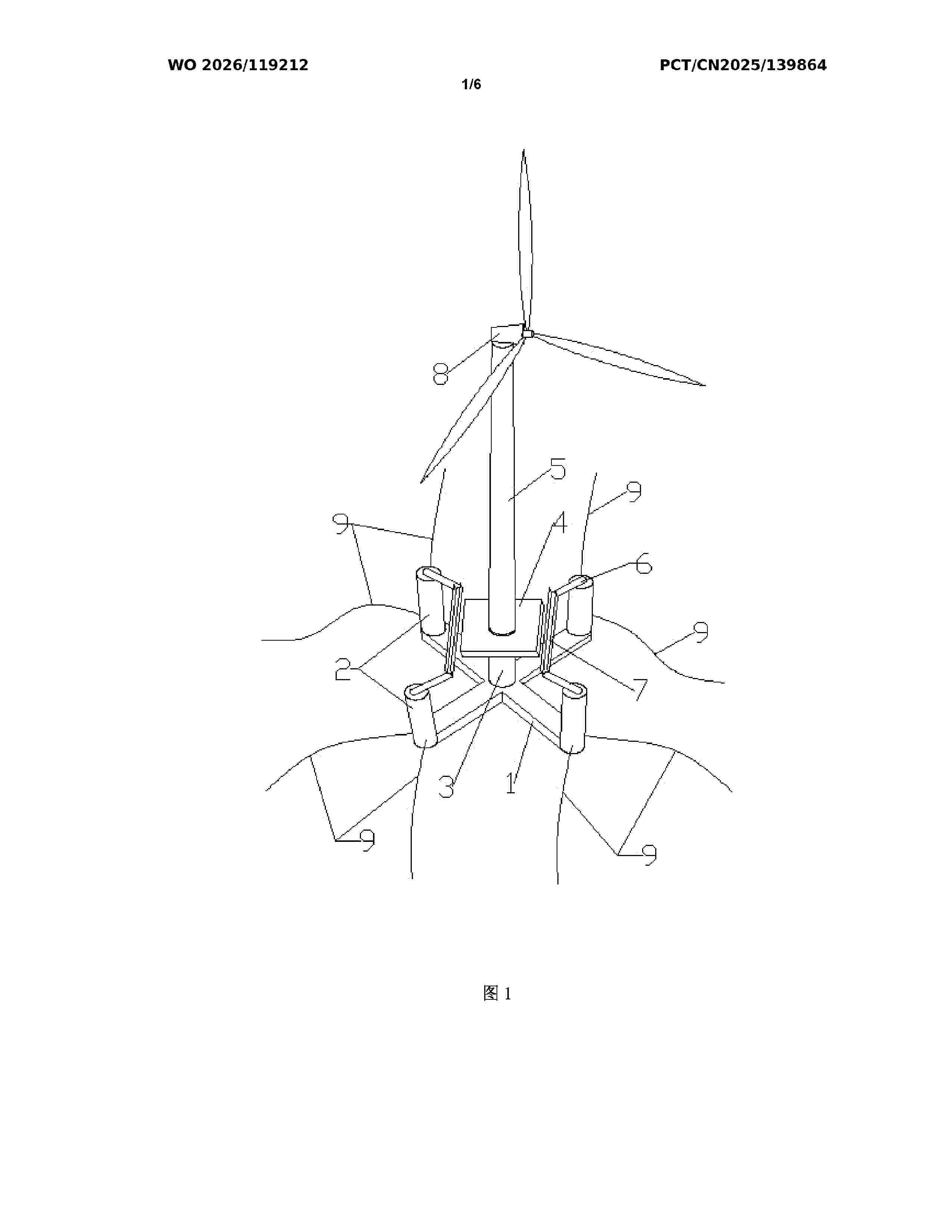
Resumen de: WO2026119212A1
Provided in the present invention are a new five-column semi-submersible wind turbine foundation and a mooring system thereof. The new five-column semi-submersible wind turbine foundation comprises an X-floater, wherein the X-floater is provided with a side column at each of the four ends thereof and is provided with a central column at the center, and the four side columns are centrosymmetrically distributed with respect to the central column; a tower is provided on the central column, a wind turbine generator system is provided at the top end of the tower, and the wind turbine generator system converts wind energy into electric energy; and an external platform is further provided on the outer peripheral surface of the junction between the central column and the tower. In the present invention, the number of side columns that provide stability is increased from three to four with respect to the prior art, which increases the moment of inertia of a waterplane by approximately 50% under the condition that the area of the waterplane remains unchanged; the stress on the structure is all transferred to the X-floater, thereby reducing the center of gravity of the structure; moreover, the communication between the side columns and the central column is realized by means of a design in which a deck passage and the external platform are staggered in terms of elevation, thereby ensuring subsequent operation and maintenance; and finally, "8x1" distributed mooring is proposed to replace
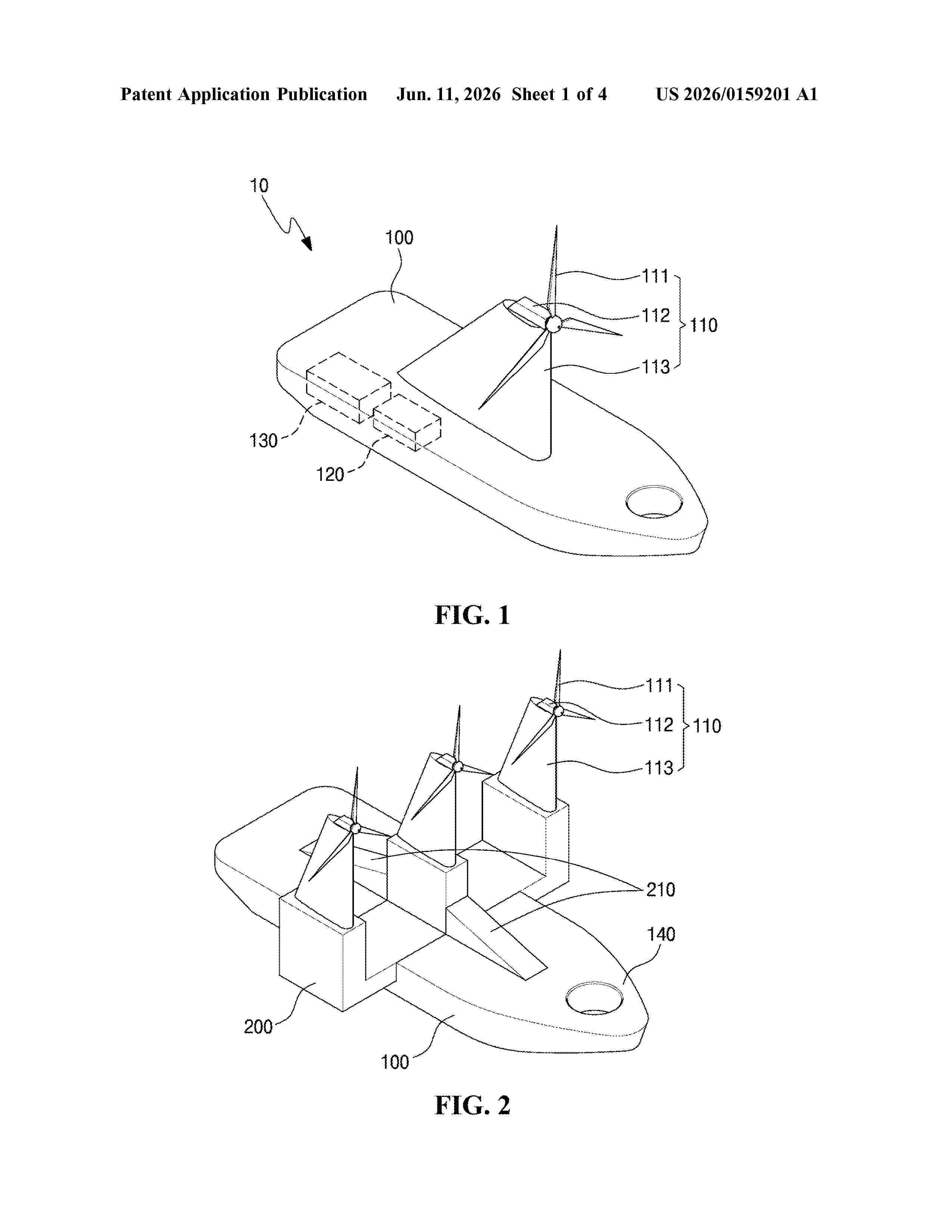
Resumen de: US20260159201A1
A marine hydrogen charging station according to one embodiment of the present invention comprises: a wind power generation unit provided on a buoyant body floating on the sea and generating electricity by using wind power; an electrolysis unit for electrolyzing seawater by using the electricity generated from the wind power generation unit; and a hydrogen storage unit for storing hydrogen generated from the electrolysis unit.
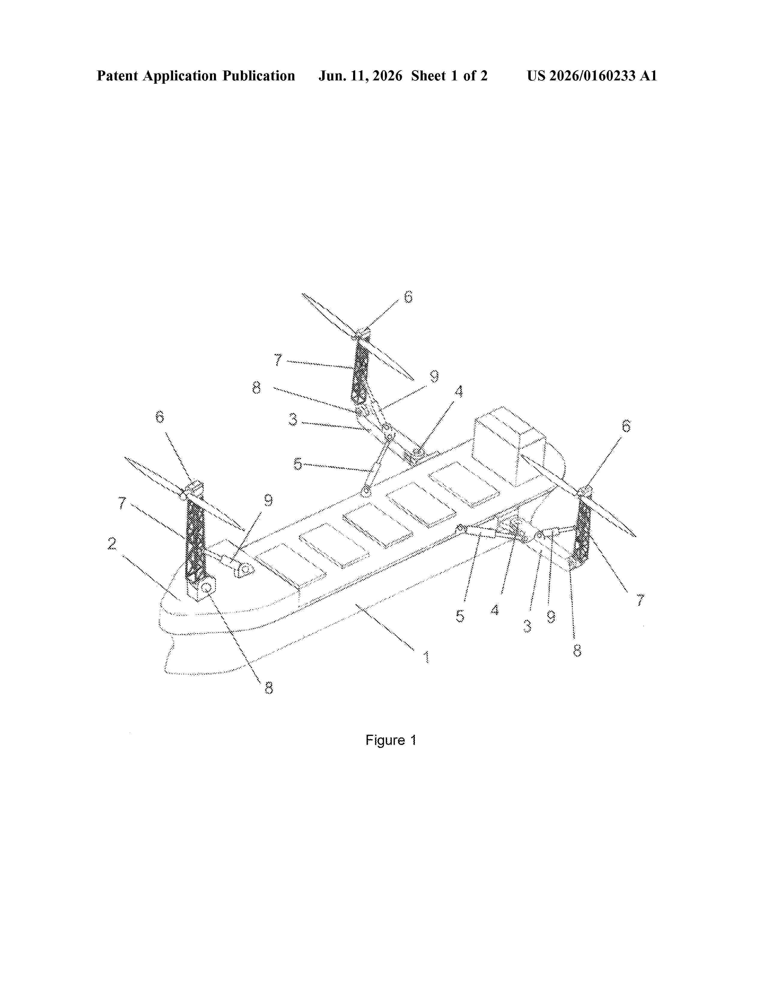
Resumen de: US20260160233A1
0000 The invention relates to wind power generation, and more particularly to systems for producing power at sea using floating vessels. The invention solves the problem of providing more efficient use of floating wind power systems. The problem of interest is solved in that a wind power system comprises a floating base in the form of a ship having on its deck three wind turbines on vertical posts, one of which is disposed on a fixed platform on the fore part of the deck, said ship additionally being provided with two rotating platforms, capable of moving in a horizontal plane, for receiving the other two wind turbines, wherein the rotating platforms are arranged symmetrically along the sides of the aft part of the ship, one on the left and the other on the right, with one end of each rotating platform being hinged to the hull of the ship and the other end supporting the base of a wind turbine post, the posts of all three wind turbines being mounted so that they can be raised and lowered and being coupled to their respective platforms by hinged joints, wherein each post is provided with its own lowering and raising mechanism, and each rotating platform is provided with its own mechanism for movement in a horizontal plane.
Resumen de: WO2025027346A1
There is provided a wave compensator for a buoy, the wave compensator including a receptacle. The receptacle has an enclosing wall having an upper end and a lower end. The receptacle also includes a first opening and a second opening arranged at different heights and configured to allow the ingress of water into and the egress of water from the receptacle, in use.
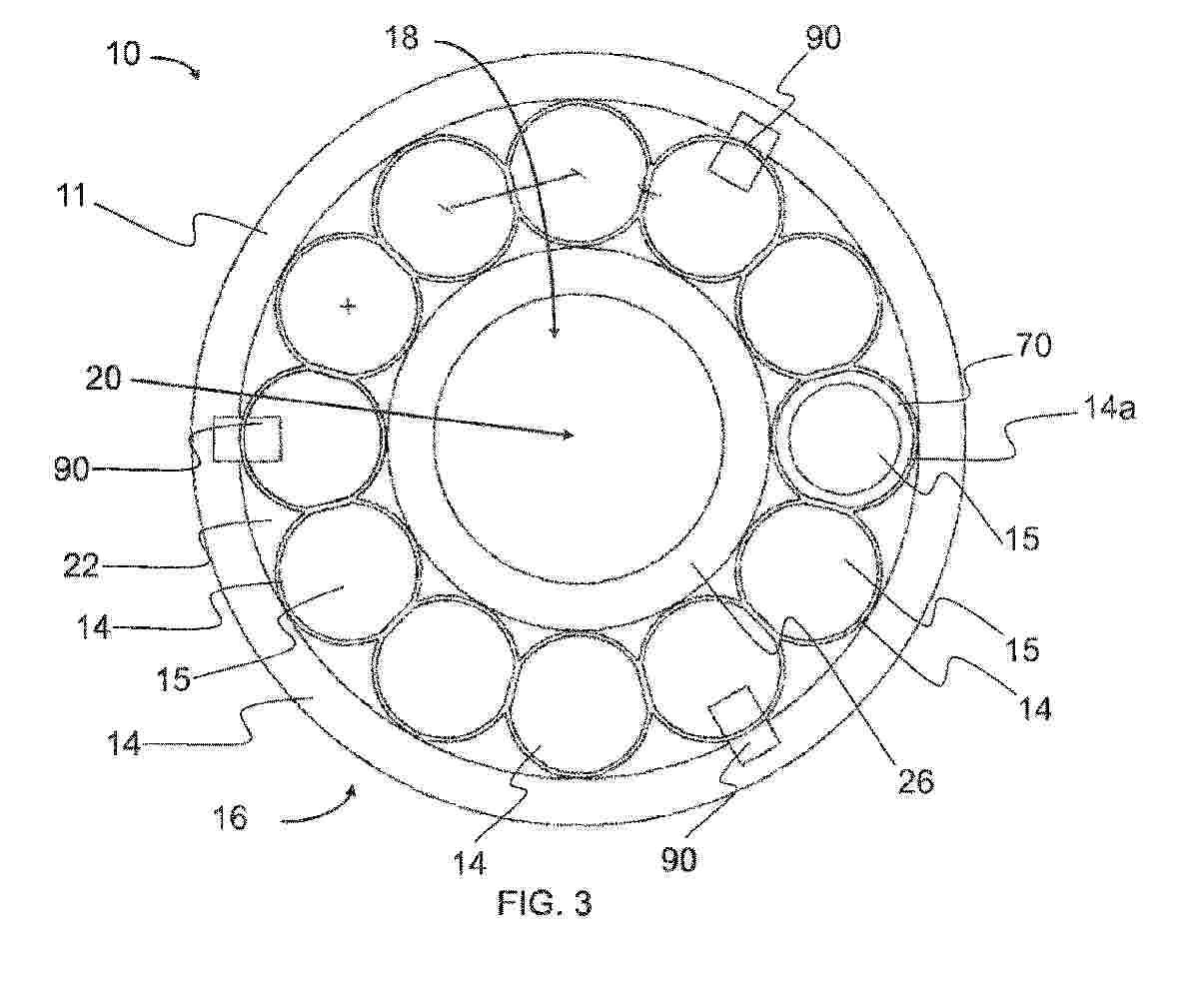
Resumen de: WO2025026978A1
A method of providing a buoyant concrete support structure (10) for an offshore installation, such as a wind turbine. A monolithic multicellular concrete member (11) is formed with at least five cells (14) arranged circumferentially around a central vertical longitudinal axis (20). The diameter of each cell (14) is smaller than a diameter of a circumference along which the cells (14) are arranged. The cells (14) are formed as vertically-extending hollow elements with an enclosed bottom portion provided below a hollow central void (15) thereabove. The cells (14) are formed contemporaneously such that all of the cells (14) are integrally-formed with each other in unison to provide the seamless monolithic multicellular concrete member (11). The cells (14) are coherent such that each cell (14) shares a common wall portion (40) with an adjacent cell (14).
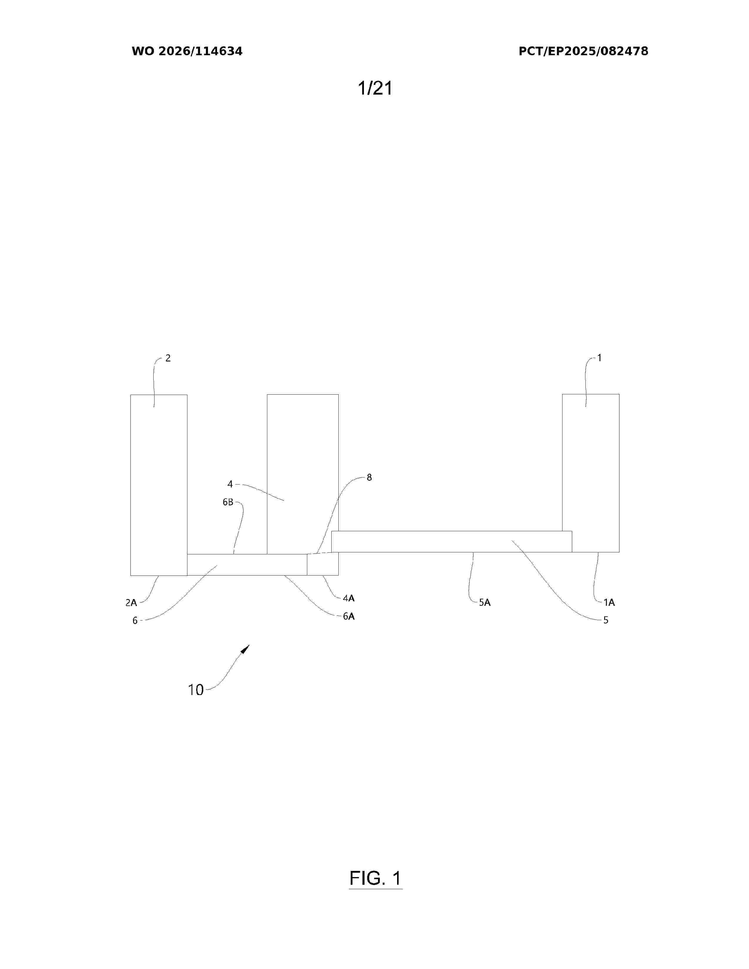
Resumen de: WO2026114634A1
The invention concerns a hull structure (10, 100, 80, 200) for a semi- submersible wind power turbine platform (50), wherein the hull structure (10) comprises: a centre column (4) configured to support a wind power tower (20) provided with a wind turbine (30), the centre column (4) being located in a central region of the hull structure (10, 100); first, second and third buoyancy structures circumferentially distributed around the centre column (4) comprising first, second and third elongated structures (5, 6, 7) connected to the centre column (4) and extending outwards in different radial directions from the centre column (4, wherein the first elongated structure (5) is located at a higher level than the second and/or third elongated structures (6, 7) so that a lower side (5A) of the first elongated connection structure (5) is located above or is substantially aligned with an upper side (6B, 7B) of at least one of the second and third elongated connection structures (6, 7).
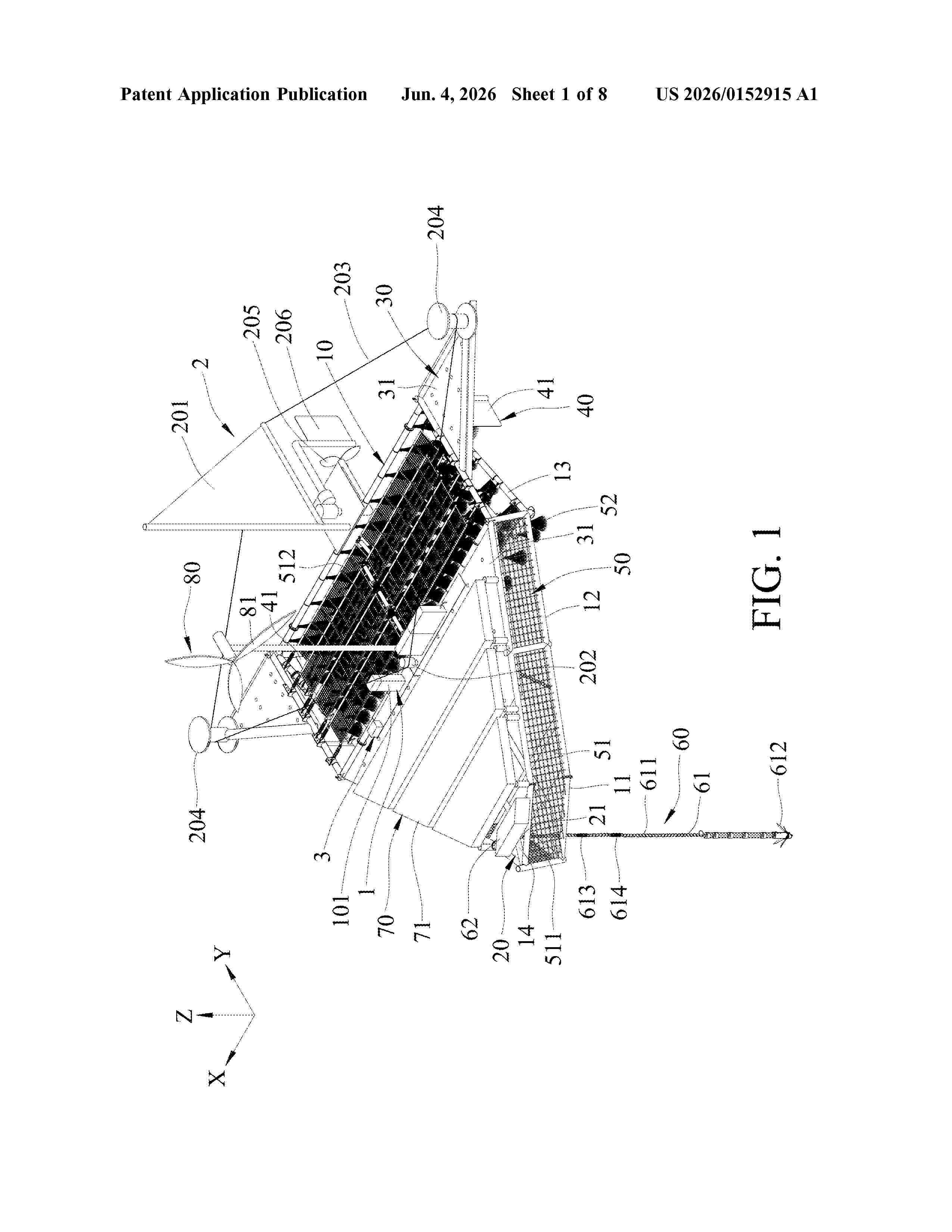
Resumen de: US20260152915A1
A floating wave-energy dissipation device includes a frame unit including a front section, a middle section and a rear section, a wave guide unit having a wave guide board, a floating plate unit having float plates, a ship fin unit having a plurality of fins, a cooling unit including a cooling controller and a cooling pipe, a heating unit including a heating controller and a heater, a positioning unit including a positioning chain, a circuit supply system including a power distribution host and being capable of supplying power to the cooling unit and the heating unit, a mobile driving unit including a canvas rack, a canvas rack motor, a bracing cable, a pair of pulleys, a propeller unit and a rudder, a central control unit, and a solar panel unit.
Resumen de: WO2025054087A1
Techniques are disclosed herein for minimizing movement of a fixed marine structure. Using the technologies described, a wind turbine may be mounted on a fixed marine platform that is secured by mooring lines coupled to one or more driven anchor piles. Each of the anchor piles may be driven into the seabed floor at an angle of batter that is less than or equal to an angle of inclination of a corresponding morning line.
Resumen de: WO2026111842A1
Offshore floating structure may include one or more mooring lines coupled to an elongated base for anchoring the elongated base to a sea floor. Offshore floating structure may further include a mounting platform coupled to the elongated base and configured to removably couple one or more power support components for supporting one or more offshore operations. The one or more power support components may comprise one or more renewable energy power sources, one or more alternative power sources, one or more power storage systems configured to store and provide energy generated from the one or more renewable energy power sources or the one or more alternative power sources, and one or more electric charging stations configured to receive the energy generated from the one or more renewable energy power sources or the one or more alternative power sources. Offshore floating structure may be manually, remotely, and/or autonomously operated.
Resumen de: US20260146584A1
A method of assembling an offshore wind turbine, such as a floating offshore wind turbine, is disclosed. The method comprises the steps of: transporting, on one or more vessels, a nacelle and a tower of the offshore wind turbine to an assembly area below a support apparatus; suspending the tower and the nacelle from the support apparatus; transporting a floating/buoyant base or foundation body to the assembly area below the support apparatus; and landing the tower on the floating/buoyant base or foundation body and the nacelle on the tower. Also disclosed is a support apparatus for assembling an offshore wind turbine, such as a floating offshore wind turbine.
Resumen de: AU2026203651A1
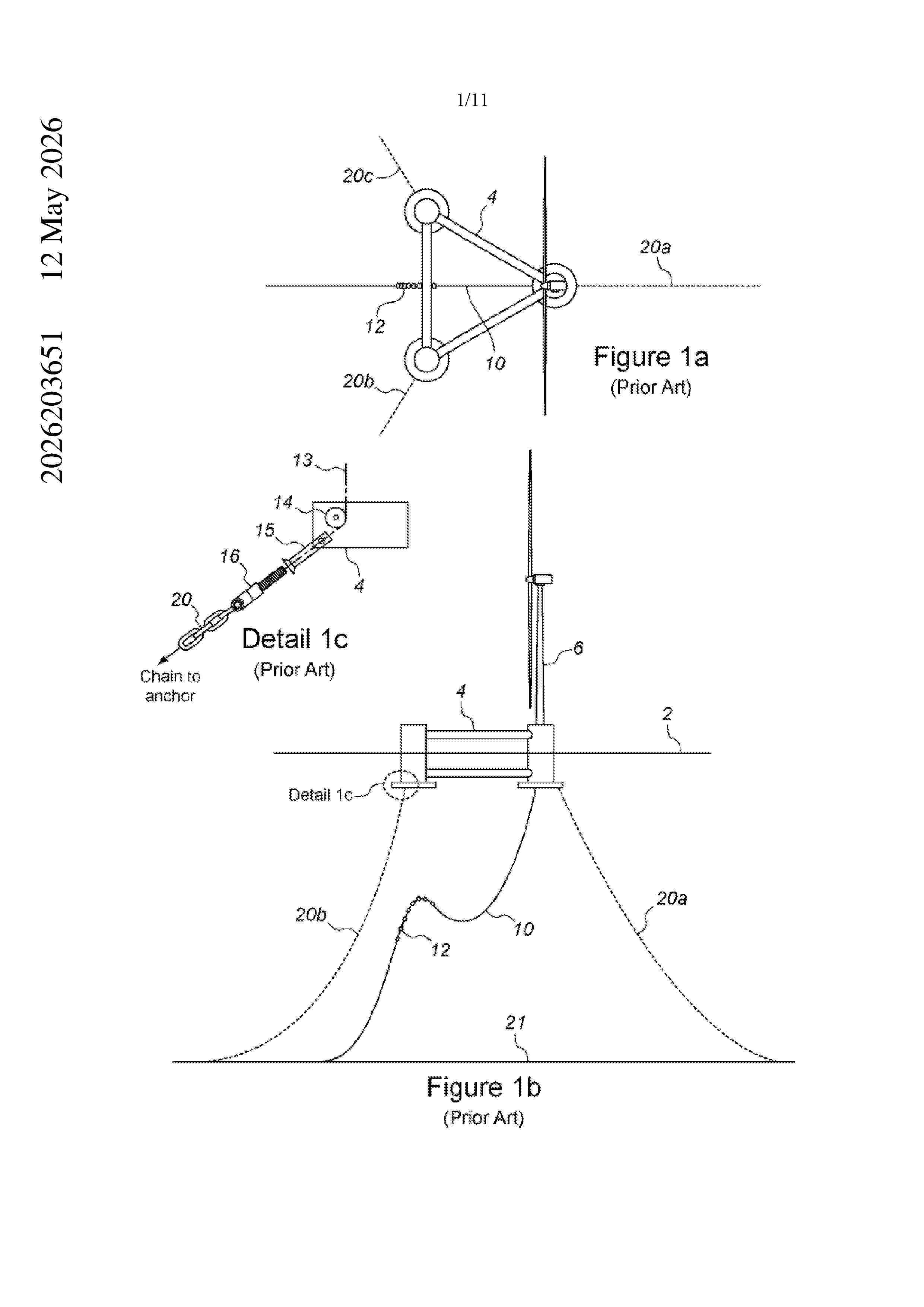
A disconnectable mooring system for offshore semi-submersible floating structures. A disconnectable buoy has a number of mooring lines which include a buoy chain between the mooring chain and the buoy. The mooring chain and the buoy chain are connected via a three way mooring connector, with the third connection configured to pull the mooring connector to a mooring point on the structure. In a first configuration the buoy is disconnected and supports the mooring chains for recovery at shallow depths to be pulled in. In a second configuration, the mooring lines are pulled in via the mooring connectors thereby providing a spread mooring to the structure with the buoy chain left as a catenary between the buoy and mooring point. ay a y
Resumen de: AU2024372340A1
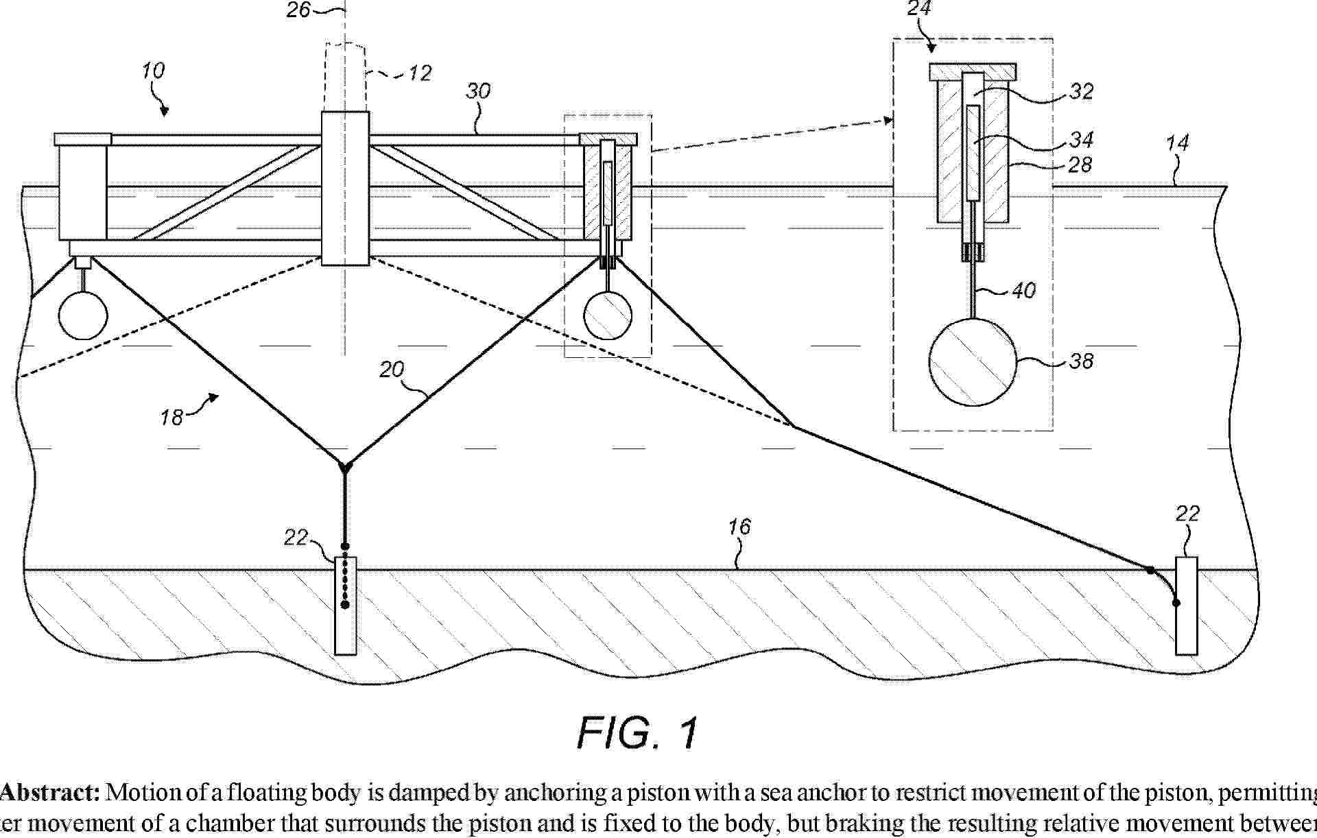
Motion of a floating body is damped by anchoring a piston with a sea anchor to restrict movement of the piston, permitting greater movement of a chamber that surrounds the piston and is fixed to the body, but braking the resulting relative movement between the chamber and the piston by displacement of fluid in the chamber. Thus, a motion damper has a brake structure that comprises a submerged sea anchor suspended in a water column and connected to a piston. The piston is movable within an elongate chamber that is in fixed relation to the floating body and that contains a fluid such as water.
Resumen de: WO2025018896A1
A mooring assembly (11; 11') for installation on a marine structure (4, 5, 6), above or below a water surface (7), comprises a main frame (101; 101') having a connecting portion (107) for connection to the marine structure. The assembly comprises a stopper device (112; 112'; 112") which is arranged in the main frame (101; 101'), and an elongate stopper member (104) which may be connected to a mooring chain or line. The stopper device (112; 112'; 112") is configured for interlocking with the elongate stopper member (104). The stopper device (112) comprises a housing (122) with a plurality of ratchet pawls (124) arranged in a circular chamber (138), wherein the pawls (124) are movably interconnected via a ring member (125) and biased towards each other by an elastic member (123), and each pawl comprises one or more ratchet teeth (133) for interaction with corresponding teeth (118) on the elongate stopper member (104).
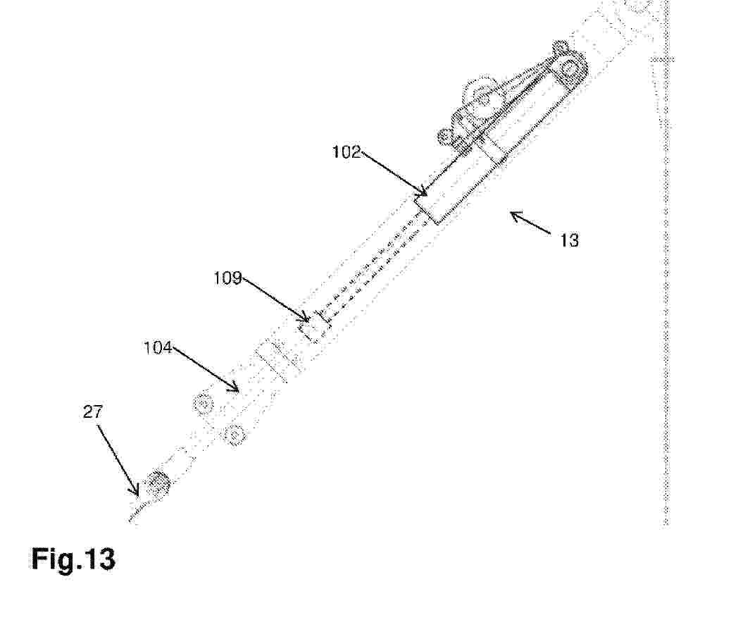
Resumen de: US20260139450A1
An anchor cage (30) for a wind turbine foundation (26 ) includes an upper load distribution flange (32), a lower base flange (34), a plurality of anchor bolts (36) coupling the upper load distribution flange (32) and the lower base flange (34), and a floating coupler (48, 48′, 48″) suspended on one anchor bolt of the plurality of anchor bolts (36). The floating coupler (48, 48′, 48″) includes a first coupler plate (54), a second coupler plate (56), and a plurality of connecting members connecting the first coupler plate (54) and the second coupler plate (56). A first portion of one anchor bolt (36) extends between and is coupled to the upper load distribution flange (32) and a first coupler plate (54) and a second portion of one anchor bolt (36) extends between and is coupled to the second coupler plate (56) and the lower base flange (34). An area bounded by the first coupler plate (54) and the second coupler plate (56) defines a passage (50) through the at least one floating coupler (48, 48′, 48″).
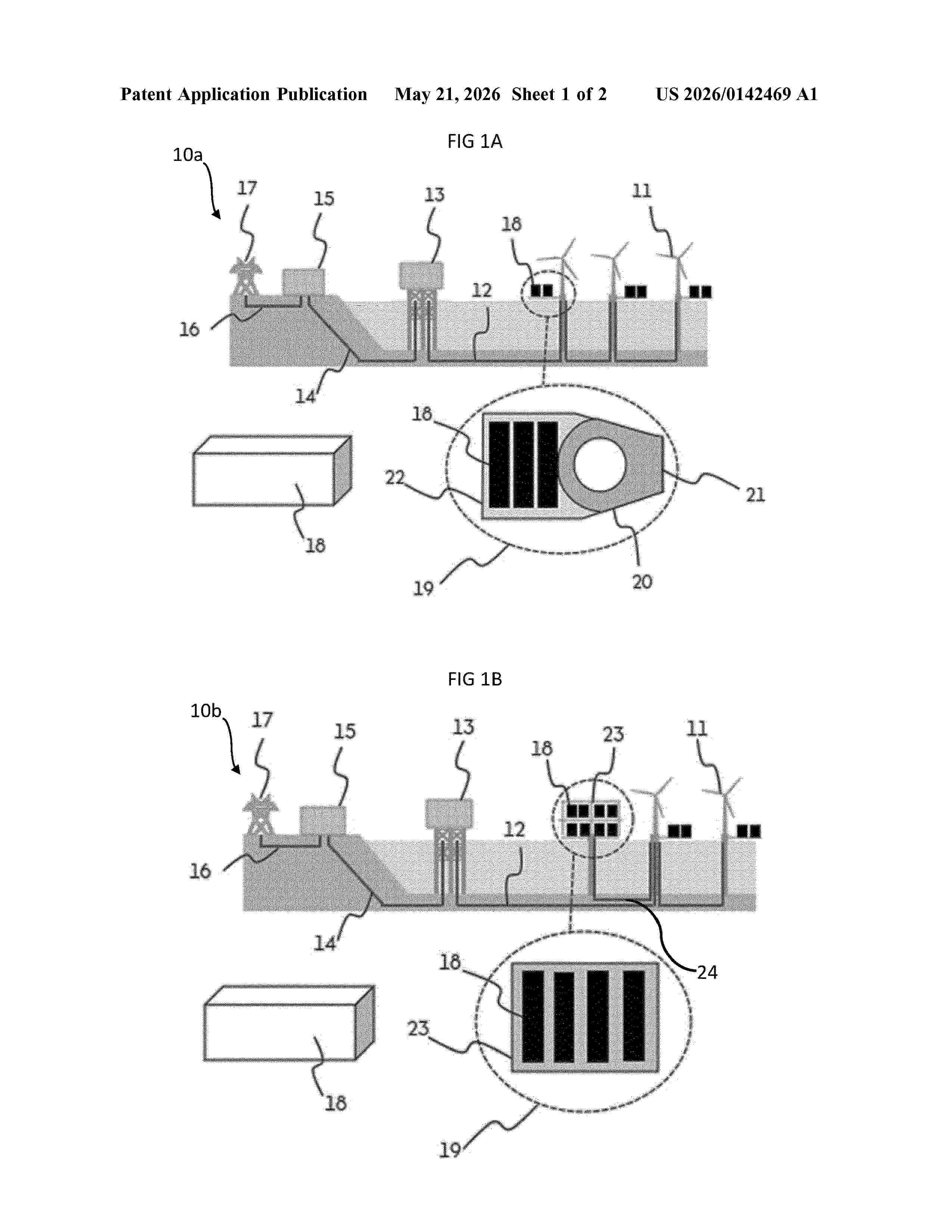
Resumen de: US20260142469A1
0000 System (10) for distributing generated electricity to an electrical network (17) and comprises at least one generator (11). A power carrying link (12) from the generators (11) to the grid is also connected to at least one service module (18), that incorporates equipment for performing a power consuming service unrelated to operation of the wind turbine and network. The service may be a computing function and benefits from being located “behind-the-meter” where cheaper energy costs are possible. For example, electricity generated by the wind turbines can be routed directly to the module(s) for use. A wind turbine generator foundation or a standalone platform configured to receive a removeable service module is also described.
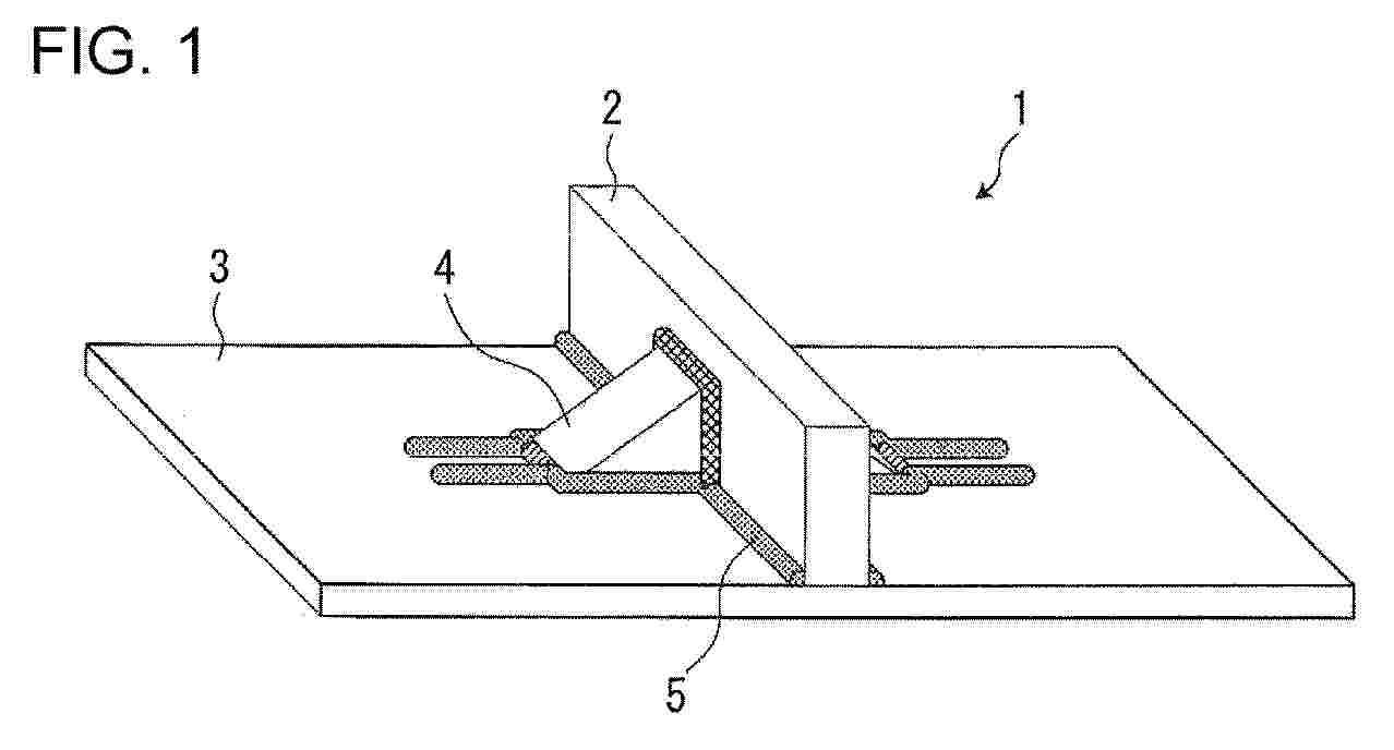
Resumen de: EP4744816A1
The present invention relates to a welded joint of a floating offshore wind-power-generation equipment including a tower member, a float member, and a bracket. The present invention provides a welded joint exhibiting increased fatigue strength at a weld with weld beads extended onto the float member, and a method of manufacturing the same. A welded joint according to the present invention includes a first weld bead, a second weld bead, and a third weld bead. The first weld bead extends along one of short edges of a rectangular contact surface at which a bracket is in contact with a float member. The second weld bead and the third weld bead extend along two respective long edges of the rectangular contact surface and are each extended over a corresponding one of a starting end and a terminal end of the first weld bead onto the float member. Furthermore, it is preferable that a ratio M/N of an interval M between a distal end part of the second weld bead and a distal end part of the third weld bead and a length N of an extended portion of the second weld bead or the third weld bead be 2.0 or smaller.
Resumen de: EP4745022A1
0001 The invention relates to a modular barge (1) comprising at least three hollow, watertight-walled floating modules (2), mechanical connection means (4) between the modules (2) and a working deck (3). Advantageously, the modules (2) may be of the ballastable type, comprising at least one ballast hole (5) that enables the flow of water between the interior of the modules (2) and the mass of water in which the barge (1) floats, at least one interconnecting air hole (6) that connects the interiors of two adjacent modules (2) and at least one regulating hole (7) that enables air to be introduced or extracted from the interior of the modules (2). Furthermore, the barge comprises means for regulating the air pressure (8) contained inside the modules (2), enabling the water level (9) inside the modules (2) to be regulated (and therefore the draught of the barge (1)) as a result of an increase or decrease of the air pressure inside the modules (2).
Resumen de: WO2026100833A1
The present invention relates to a leg-fixing system for a jacking-type offshore wind power generation platform, which enables legs to be smoothly fixed inside a platform after the operation of a portable jacking system in a floating offshore wind power generation platform constructed using a jacking method, and which improves maintenance-related performance even through various environmental changes.
Nº publicación: WO2026099364A1 15/05/2026
Solicitante:
LANKHORST EURONETE PORTUGAL S A [PT]
LANKHORST EURONETE PORTUGAL, S.A.
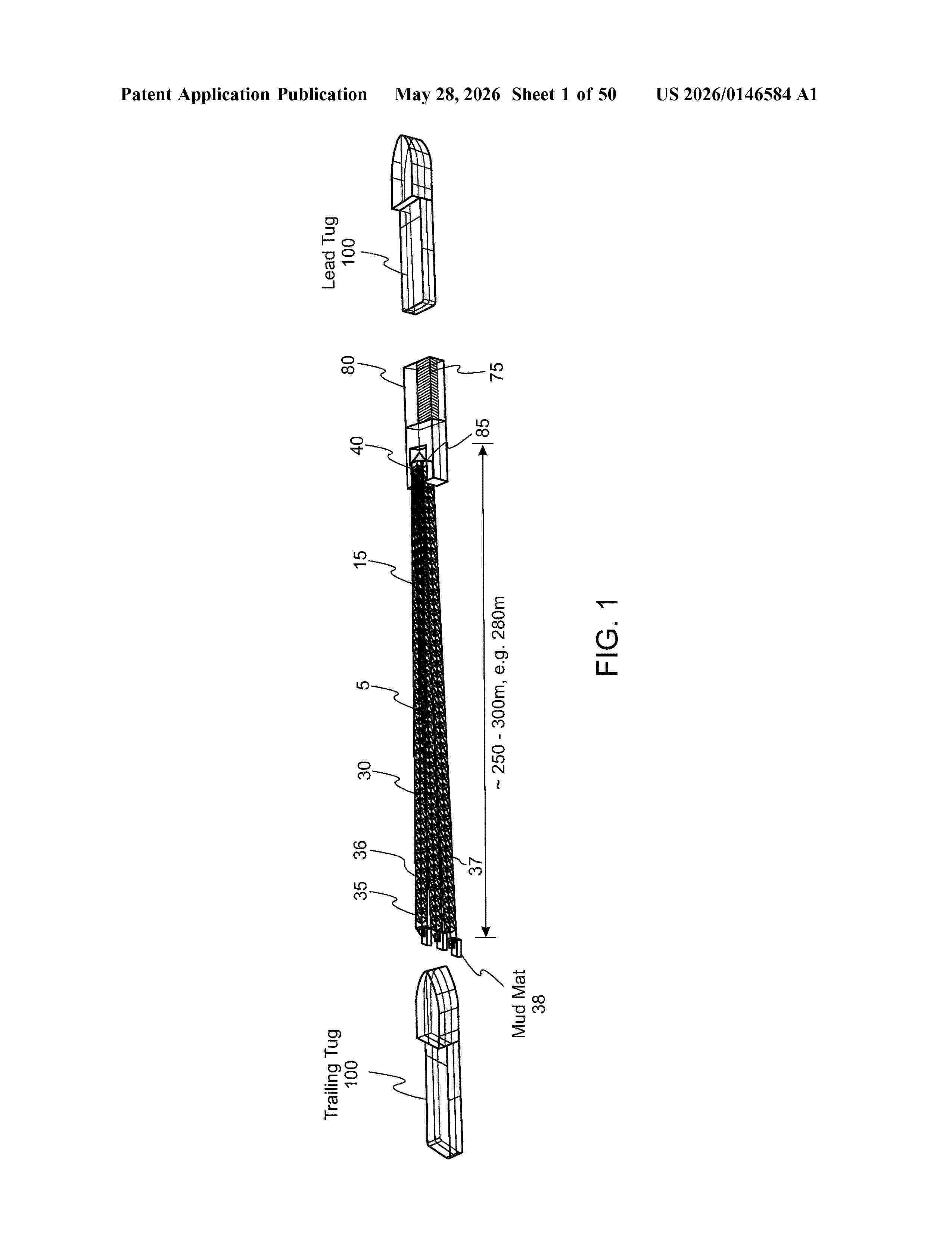
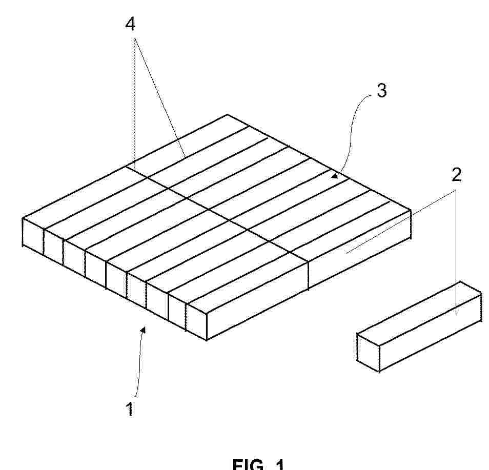
Resumen de: WO2026099364A1
The invention is directed to a reusable tension element for a tendon for tension leg platforms, said tension element comprising a lamella comprising two terminal ends and having an essentially rectangular cross-section with an aspect ratio that is defined as the ratio between the longest side and the shortest side of the rectangle of at least 10, preferably at least 15, wherein said lamella has thickness of at least 1 mm, and a length of at least 20 m, wherein said lamella comprises a material having an elastic modulus of more than 50 GPa. Further aspects of the invention are a tendon comprising said elements, a transportation system to transport said elements, and a tension leg platform that is tethered to a seabed with said tendons.
 BOPI
BOPI
 Sede Electrónica