Si deseas distinguir tus productos, servicios o ambos de los de otra empresa, es posible que necesites una marca o nombre comercial. Descubre qué son, en qué consiste su procedimiento de registro y qué implica.

Información sobre los plazos de presentación de solicitudes de transformación de marcas de la Unión Europea en marca nacional española. Más información


Si tienes un nuevo dispositivo, producto o procedimiento que resuelva un problema técnico o tenga una ventaja práctica, existen distintas formas de protegerlo en España y en otros países. Descubre cómo hacerlo.

¿Tu innovación reside en la estética, la ornamentación o la apariencia de tu producto? Protégela mediante un diseño industrial. Descubre qué derechos confiere el registro y cómo realizar la tramitación.

Las patentes publicadas en todo el mundo son una valiosa fuente de información científica, técnica y comercial.
El Bono 3 del Fondo para pymes 2025, que cubre la elaboración de Informes Tecnológicos de Patentes (ITP) y Búsquedas Retrospectivas se reabrirá el lunes 2 de junio de 2025. Puede consultar más información aquí.

Si eres emprendedor/a o una empresa y quieres potenciar y mejorar la rentabilidad de tu negocio protegiendo de forma adecuada los activos intangibles de tu organización, en este espacio encontrarás lo necesario.


 220
resultados
220
resultados
 Última actualización
16/05/2025 [06:59:00]
Última actualización
16/05/2025 [06:59:00]


 Resultados 50 a 75 de 220

Resumen de: DE102023130403A1
Photovoltaik-Anlage (1) mit einer Tragkonstruktion mit einer Vielzahl von in einem Untergrund (3) verankerbaren Pfosten (2) und mindestens einem bifazialen Photovoltaikmodul (4) zwischen zwei benachbarten Pfosten (2), wobei das mindestens eine bifaziale Photovoltaikmodul (4) an vier Ecken an jeweils einem Halteelement (5) gehalten ist und jedes Halteelement (5) an einem der Pfosten (2) fixiert ist. Ferner betrifft die Erfindung ein Verfahren zur Montage einer Photovoltaik-Anlage (1), die mit geringem Materialeinsatz aufgestellt werden kann und leicht zu montieren ist.

Resumen de: WO2025091790A1
A photovoltaic module backsheet, comprising: a metal layer, which comprises a first surface and a second surface arranged opposite each other in the direction of thickness thereof; and an insulating enclosure layer, which comprises a first insulating cover layer arranged on the first surface of the metal layer and a second insulating cover layer arranged on the second surface of the metal layer, wherein the edges of the first insulating cover layer and the second insulating cover layer both protrude beyond the edge of the metal layer, and the portions of the first insulating cover layer and the second insulating cover layer that protrude beyond the edge of the metal layer are connected together, thus enclosing the metal layer between the first insulating cover layer and the second insulating cover layer, each of the first insulating cover layer and the second insulating cover layer comprising at least one first insulating layer.
Resumen de: WO2025091198A1
A photovoltaic module and a manufacturing method therefor. The photovoltaic module comprises a front plate, a cell layer, and a back plate, wherein the cell layer is located between the front plate and the back plate; encapsulant film layers are provided between the cell layer and the back plate and between the cell layer and the front plate; the area of the cell layer is smaller than the area of the front plate and/or the back plate, so that the front plate and/or the back plate have a sealing edge extending beyond the peripheral edges of the cell layer; and a plurality of protrusions are provided on the inner surface of the sealing edge. The photovoltaic module further comprises a sealant strip arranged around the cell layer, wherein the sealant strip is laminated between the front plate and the back plate, at least one of the upper surface and the lower surface of the sealant strip is in contact-fit with the protrusions, and a portion of the sealant strip is pressed into the region to be filled between the protrusions. The photovoltaic module has improved interface water blocking capacity, thereby improving the water vapor resistance of the photovoltaic module.
Resumen de: WO2025092659A1
The present application relates to the technical field of photovoltaics, and discloses a photovoltaic module, so as to solve the problems of significant visual differences and poor aesthetics of photovoltaic modules. The photovoltaic module comprises a cover plate, cells, and a packaging plate which are sequentially stacked from top to bottom. A passivation layer is provided on the surface of each cell on the side facing the cover plate. The refractive index of the passivation layer is greater than or equal to 1.9 and less than or equal to 2.3. The thickness of the passivation layer is greater than or equal to 50 nm and less than or equal to 100 nm. The cover plate is provided with an anti-reflection layer, and the anti-reflection layer is located on the side of the cover plate away from the cells. The thickness of the anti-reflection layer is greater than or equal to 100 nm and less than or equal to 230 nm. The refractive index of the anti-reflection layer is greater than or equal to 1.1 and less than or equal to 1.4.
Resumen de: WO2025092330A1
The present disclosure provides a perovskite cell and a preparation method therefor, and a photovoltaic module. The perovskite cell comprises a substrate, and a perovskite layer (3) and an electron transport layer which are sequentially arranged on the substrate, wherein the electron transport layer comprises a C60 layer, and the C60 layer is arranged close to the perovskite layer, wherein the perovskite layer (3) comprises a perovskite material and 1,3-diaminopropane dihydroiodide, and/or the perovskite cell further comprises a passivation layer (4) arranged between the perovskite layer and the C60 layer, and the passivation layer (4) comprises 1,3-diaminopropane dihydroiodide.
Resumen de: DE102023130837A1
Die Erfindung geht aus von einer Solarmodulbefestigungsvorrichtung mit einer Montageschiene (34, 36, 38, 40) zur Befestigung mehrerer Solarmodule(12, 14, 16, 18), wobei die Montageschiene (34, 36, 38, 40) zumindest eine zumindest im Wesentlichen durchgängige Auflagefläche (44, 46) aufweist, auf die die Solarmodule (12, 14, 16, 18) zur Befestigung aufschiebbar sind.Es wird vorgeschlagen, dass die Montageschiene (34, 36, 38, 40) zumindest ein Montagesicherungselement (66, 68) aufweist, das dazu vorgesehen ist, ein Aufschieben von Solarmodulen (12, 14, 16, 18) auf die Auflagefläche (44, 46) in einer Montagerichtung (204) zuzulassen und die Solarmodule (12, 14, 16, 18) in Montagepositionen gegen ein Verschieben entgegen der Montagerichtung (204) zu sichern.
Resumen de: WO2025092041A1
A connector (11), comprising: a connection body (300); a first connecting assembly (100), which comprises a first connecting line (110) and a first plug-in member (120), the first connecting line (110) being connected to the connection body (300) and located on one side of the connection body (300), and the first plug-in member (120) being connected to one end of the first connecting line (110) away from the connection body (300); and a second connecting assembly (200), which comprises a second plug-in member (220), the second plug-in member (220) being located on the other side of the connection body (300), and one of the first plug-in member (120) and the second plug-in member (220) being a male plug and the other being a female socket adapted to the male plug.
Resumen de: WO2025091805A1
The present application relates to a pressing block and a photovoltaic device. The pressing block (100) is used for assembling a first battery module (200) to a second battery module (300), and comprises a body (110), first fitting members (120), and second fitting members (130); the first fitting members (120) are arranged on the body (110), and the first fitting members (120) are fitted to the first battery module (200); the second fitting members (130) and the first fitting members (120) are arranged at two ends of the body (110) in a first direction in a one-to-one correspondence manner, and the second fitting members (130) extend out of the side of the body (110) facing away from the first fitting members (120); the first direction is the arrangement direction of the first battery module (200) and the second battery module (300); when the second battery module (300) gets close to the pressing block (100) in the first direction, the second fitting members (130) can elastically deform in a second direction, so that the body (110) is fitted to the second battery module (300); and the second direction is the thickness direction of the pressing block (100).
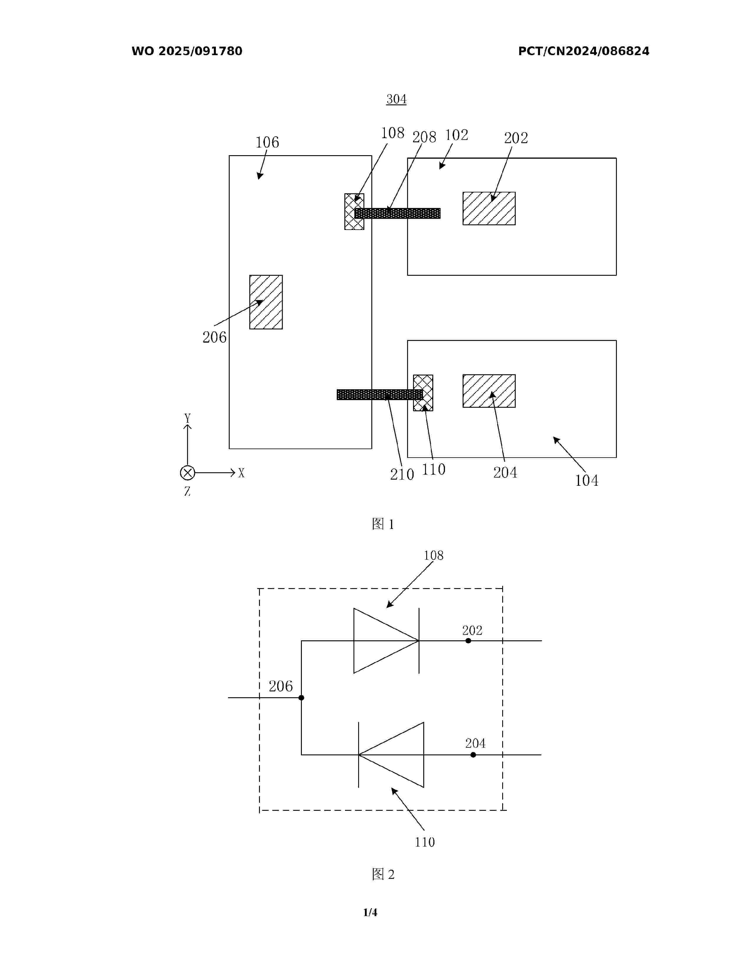
Resumen de: WO2025091780A1
The present application relates to a photovoltaic bypass device, a photovoltaic module junction box, and a photovoltaic module. The photovoltaic bypass device comprises: a first conductive block (102) provided with a first welding area (202); a second conductive block (104) spaced apart from the first conductive block (102) and provided with a second welding area (204); a third conductive block (106) spaced apart from both the first conductive block (102) and the second conductive block (104) and provided with a third welding area (206); a first bypass element (108), a terminal of the first bypass element (108) that has a first polarity being electrically connected to the first conductive block (102), a terminal of the first bypass element (108) that has a second polarity being electrically connected to the third conductive block (106), the second polarity being opposite to the first polarity; and a second bypass element (110), a terminal of the second bypass element (110) that has the second polarity being electrically connected to the second conductive block (104), and a terminal of the second bypass element (110) that has the first polarity being electrically connected to the third conductive block (106).
Resumen de: WO2025093841A1
The present disclosure relates to a floating modular assembly (1) comprising at least two floating devices (D1, D2, D3) and a connecting system, configured to mechanically connect the at least two floating devices, the connecting system comprising - a first coupling element (E1), rigidly attached to and projecting laterally from a first floating device (D1) - a second coupling element (E2), rigidly attached to and projecting laterally from the second floating device (D2) - a removable locking system, configured to connect the first coupling element to the second coupling element.
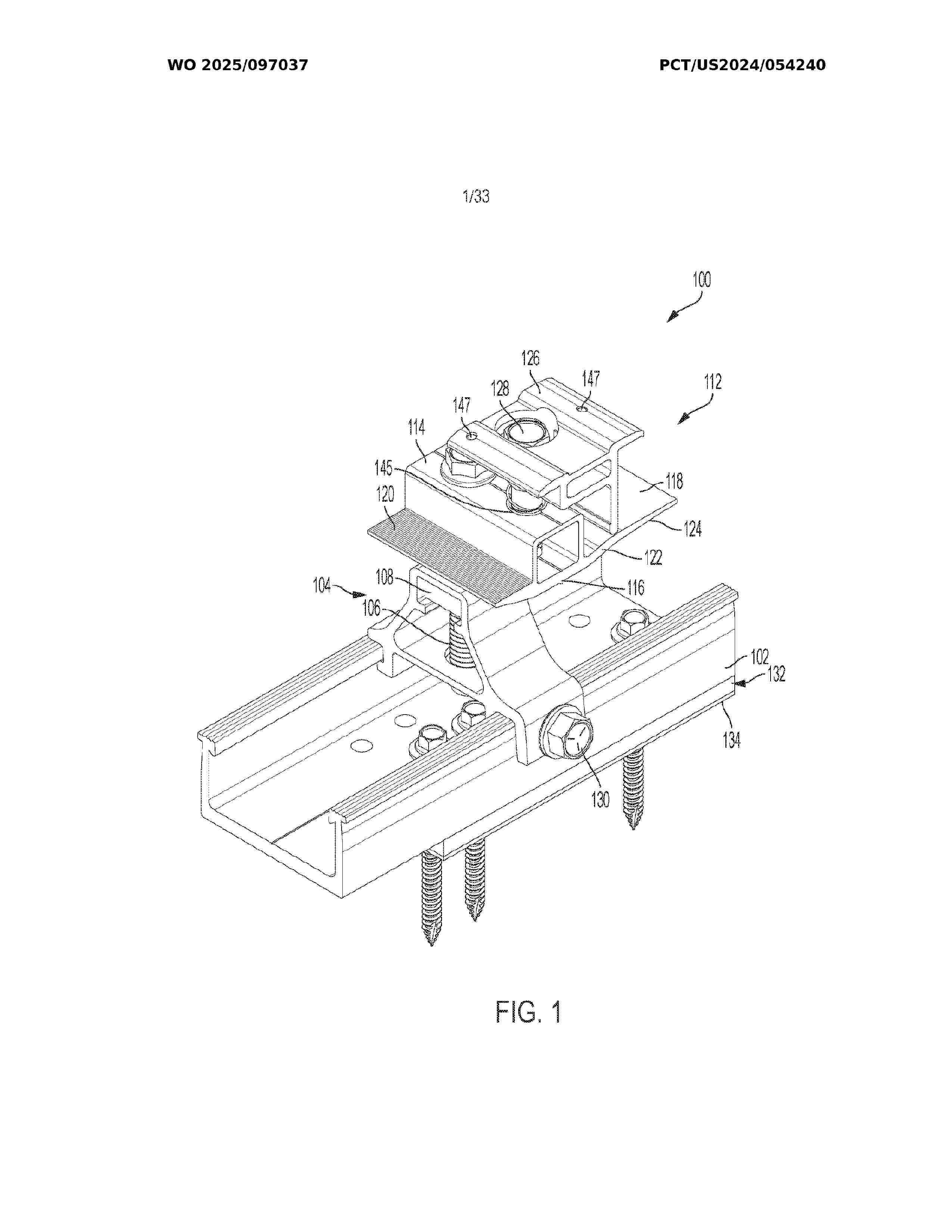
Resumen de: WO2025097037A1
A roof mount (700) includes a base assembly installable on a roof including a foot (703), an arm (705), and a slider (707). A flashing (780) is positioned between the foot (703) and the arm (705) and an adjustment assembly (704) is coupled to the slider (707). The adjustment assembly (704) includes a partially threaded shaft (706), an adjustment nut (708), and a support nut (710). A clamp (712) is adjustably connected to the base assembly by the adjustment assembly (704) and a distance between the clamp (712) and the slider (707) is adjustable. The clamp (712) includes a first clamp portion (714) and a second clamp portion (726). The first clamp portion (714) includes a central portion (716), a first support surface (718), and a second support surface (720). The central portion (716) is disposed between the first support surface (718) and the second support surface (720). A first fastener (728) is connected to the clamp (712) and operable to tighten the second clamp portion (726) to the first clamp portion (714). A roof mount system includes a roof mount (700) and at least one skirt (400).
Resumen de: WO2025091743A1
A solar panel assembly (10) and a railing assembly (50). The solar panel assembly (10) comprises: a solar panel (100), the solar panel (100) being provided with at least one connecting hole group (110), and each connecting hole group (110) comprising a plurality of connecting holes (112) arranged at intervals; and at least one connecting structure (200), each connecting structure (200) matching one connecting hole group (110), each connecting structure (200) comprising a pull rope (210), the pull rope (210) successively passing through the plurality of connecting holes (112) of the connecting hole group (110), and the portion of the pull rope (210) passing through the plurality of connecting holes (112) comprising a first tensioning section (212) and a second tensioning section (214), the first tensioning section (212) being located on a first side of the solar panel (100), the second tensioning section (214) being located on a second side of the solar panel (100), and the first side of the solar panel (100) and the second side of the solar panel (100) being arranged opposite to each other.
Resumen de: WO2025095234A1
A portable counting device using a tripod and a solar cell comprises: a tripod unit; a camera module disposed on the tripod unit and for photographing an image of a preset region of interest; a driving unit for counting the number of objects located in the region of interest by analyzing the image photographed by the camera module; a wireless communication module for sending information on the counted number of the objects to a server; and a power supply unit for supplying power required to drive the camera module, the driving unit, and the wireless communication module, the device thus being capable of easily counting the number of objects in the region of interest even in an environment in which power is not provided.
Resumen de: WO2025095235A1
This counting system comprising a portable counting device using artificial intelligence may comprise: at least one counter for extracting information on the number of preset objects, corresponding to a preset region of interest, in a counting mode; a server for receiving the information on the number of objects from the at least one counter; and a host terminal corresponding to a host user.
Resumen de: WO2025095351A1
Provided is an electronic device comprising: a memory; and a processor operatively connected to the memory, wherein the processor is configured to: receive multiple pieces of weather forecast data; acquire multiple pieces of characteristic data on the basis of the multiple pieces of weather forecast data; acquire integrated characteristic data obtained by integrating the multiple pieces of characteristic data on the basis of similarity between the multiple pieces of characteristic data; and generate a prediction value of solar power generation on the basis of the integrated characteristic data.
Resumen de: WO2025094603A1
The present invention addresses the problem of providing a method for manufacturing a high-productivity solar cell with which high performance is achieved in a solar cell. The aforementioned problem can be solved by a method for manufacturing a solar cell, the method comprising: a precursor formation step for forming a precursor having an InGaSe layer, a CuSe layer, and an InSe layer; and a crystallization step for heating the precursor to obtain a crystallized light absorption layer.
Resumen de: WO2025096457A1
An on-site photovoltaic (PV) module assembly system and process may involve customizing assembly of a row of PV modules at the location of a particular solar site. Mounting rails or other mounting structures configured to interface a PV module with a torque tube may be positioned along the torque tube on site to account for physical characteristics and properties of the particular solar site. PV modules may be attached to one or more of the mounting rails by an adhesive. Using the adhesive to attach the PV modules to the mounting rails may increase the flexibility of PV module installation along the torque tube. Use of the adhesive may also decrease the number of fastening components included with the mounting rail and the PV module, such as a structural rail or module rails.
Resumen de: WO2025097102A1
Reflective fibers include prismatic fibers are configured to reflect solar radiation and may be incorporated into a textile or fabric and formed into garment or architectural textiles. A prismatic fiber may be a different material of polymer from a carrier material within the fiber or may be a void. A prismatic fiber or void has a triangular cross-sectional shape across the length of the fiber and may have one or more sides that are textured, corrugated or have a plurality of grooves to reflect light to increase the overall reflectance of light and solar radiation back in the atmosphere, away from the prismatic fiber. Light may enter the first side of the prismatic fiber and reflect off the base and out the second side of the prismatic fiber, wherein the texture or grooves act as a Fresnel lens. The fibers may be woven into a fabric, or laid down as a non-woven or configured on a substrate or support layer. A prismatic fiber may be made out of a polymeric material.
Resumen de: WO2025097074A1
Illustrative embodiments present a self-contained window system that includes a solar-generating glass window, pods that contain components, an energy storage device, and electrical circuits that distribute electrical power that is generated by the solar-generating glass and distributed to the components and the energy storage device. The self-contained window system is secured to a structure that may be a window frame, a glazing bead, or the like. In illustrative embodiments, the pods are secured inside of the structure, while in other illustrative embodiments the pods are secured on the outside of the structure. Regardless of whether the pods are secured inside or outside of structure, the components in the pods are accessible and easy to maintain. The pods and components can be conveniently exchanged and upgraded.
Resumen de: WO2025095811A1
The invention relates to the solar power industry. A linear cable system for cleaning solar panels comprises a control unit and a cleaning module. The control unit comprises a computer and a wireless communication module. The cleaning module, which is mounted on a row of solar panels, comprises a starting platform, a receiving platform, a cleaning device, and a cable system. The starting platform consists of a frame for an electric motor, a drive attachment frame, two driven pulleys, guide rails, and struts. The receiving platform consists of a drive attachment frame, two guide pulleys, guide rails, and struts. The guide rails are fastened to a crossbar, and the struts are fastened to support posts. The cable system contains a power shaft connected to the electric motor and to the guide pulleys, the guide pulleys being mounted on the ends of the receiving platform. Cables are threaded around the pulleys in such a way that between a cable and the surface of a solar panel there is a gap. The cables are tensioned by means of ratcheting mechanisms on a sheave assembly of a rotary drive of the cleaning device. The invention provides an increase in the reliability and service life of the equipment, an increase in cleaning power, and a broadening of the functional capabilities and scope of use of the system.
Resumen de: WO2025096812A1
In some implementations, a system includes a plurality of photovoltaic panels that are each configured to generate a DC voltage. The system includes a plurality of converter modules that each include a DC-DC converter. The converter modules are electrically coupled together to provide DC output in parallel to a DC bus. Each of the converter modules is configured to receive input of a DC voltage from at least one of the photovoltaic panels and is also configured to convert the received DC voltage to an output DC voltage. The system includes a DC-AC converter configured to receive DC power from the DC bus and provide an AC output.
Resumen de: US2025143258A1
Apparatuses, systems, and methods are provided for controlling one or more assemblies of an energy generation system. The method may include selecting at least a portion of the one or more assemblies, transmitting at least one control signal associated with the selected at least a portion of the one or more assemblies, receiving the control signal at a communication module of the one or more assemblies, and modifying an operational parameter of the one or more assemblies responsive to the received control signal to avoid contact between the one or more assemblies and obstacles. The operational parameter may be associated with a position of the at least a portion of the one or more assemblies relative to a ground surface. The operational parameter may additionally or alternatively be a range of angle of the at least a portion of the one or more assemblies.
Resumen de: US2025145466A1
Methods for stabilizing laser-induced graphene (LIG) through composite formation and compositions thereof. Using infiltration methods and/or lamination methods, LIG composites (LIGCs) with physical properties can be engineered on various substrate materials. The physical properties include surface properties, such as superhydrophobicity and antibiofouling; the LIGCs are also useful in antibacterial applications, Joule-heating applications, and as resistive memory device substrates. Further, methods for fabricating and using LIG for flexible and embeddable gas sensors.
Resumen de: US2025147545A1
A display device and a method of manufacturing the display device are provided. The method includes disposing a display panel, including side areas, a front display area, and a sub-region, on a carrier film including first, second, and third release portions; removing the first release portion to expose the side areas; disposing a cover window above the display panel; attaching the front display area to the cover window by pressing the second release portion toward the cover window, and attaching the side areas to the cover window by pressing the side areas exposed by removing the first release portion toward the cover window; removing the second release portion and the third release portion to expose the front display area and the sub-region; and bending the display panel to attach a bottom portion of the sub-region to a bottom portion of the front display area.
Nº publicación: US2025147120A1 08/05/2025
Solicitante:
SOLAREDGE TECH LTD [IL]
Solaredge Technologies Ltd
Resumen de: US2025147120A1
Systems and/or methods for mapping power device in a string of serially connected power devices are disclosed herein. A power source may apply a source voltage to a first end of the string. A power system controller coupled to the two ends of the string may send a first signal to the power devices in the string. The power devices in the string, responsive to receiving the first signal, may measure electrical characteristics of the power devices, where the measured electrical characteristics may indicate the parasitic leakage of the power devices. The power devices may send second signals to the power system controller to report the measured electrical characteristics. The power system controller may determine the mapping of the power devices in the string based on the second signals.
 BOPI
BOPI
 Sede Electrónica