Si deseas distinguir tus productos, servicios o ambos de los de otra empresa, es posible que necesites una marca o nombre comercial. Descubre qué son, en qué consiste su procedimiento de registro y qué implica.

Información sobre los plazos de presentación de solicitudes de transformación de marcas de la Unión Europea en marca nacional española. Más información


Si tienes un nuevo dispositivo, producto o procedimiento que resuelva un problema técnico o tenga una ventaja práctica, existen distintas formas de protegerlo en España y en otros países. Descubre cómo hacerlo.

¿Tu innovación reside en la estética, la ornamentación o la apariencia de tu producto? Protégela mediante un diseño industrial. Descubre qué derechos confiere el registro y cómo realizar la tramitación.

Las indicaciones geográficas protegen el nombre de un producto originario de una zona geográfica, a la cual le debe una determinada calidad, reputación u otra característica. Descubre qué son, en qué consiste su procedimiento de registro y qué beneficios conceden.

Las patentes publicadas en todo el mundo son una valiosa fuente de información científica, técnica y comercial.

Si eres emprendedor/a o una empresa y quieres potenciar y mejorar la rentabilidad de tu negocio protegiendo de forma adecuada los activos intangibles de tu organización, en este espacio encontrarás lo necesario.


 634
resultados
634
resultados
 Última actualización
01/04/2026 [08:11:00]
Última actualización
01/04/2026 [08:11:00]


 Resultados 350 a 375 de 634

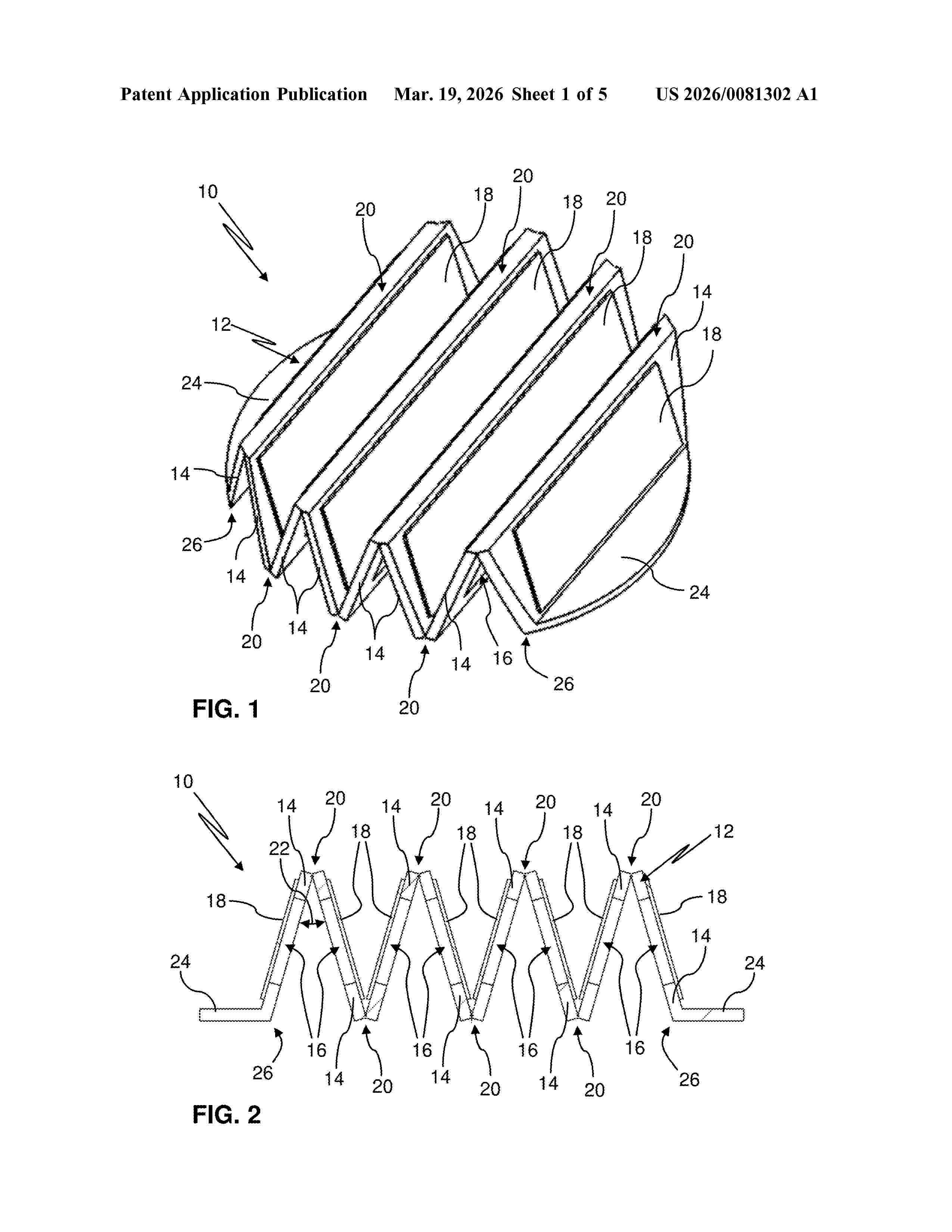
Resumen de: US20260081302A1
A venting unit for a battery case, the venting unit comprising a housing part delimiting a vent opening, and a membrane assembly spanning across the vent opening and comprising a membrane carrier comprising carrier segments and flow windows respectively disposed through the carrier segments, and membrane segments respectively covering the flow windows. Each adjacent pair of the carrier segments is folded against one another along a film hinge disposed therebetween.

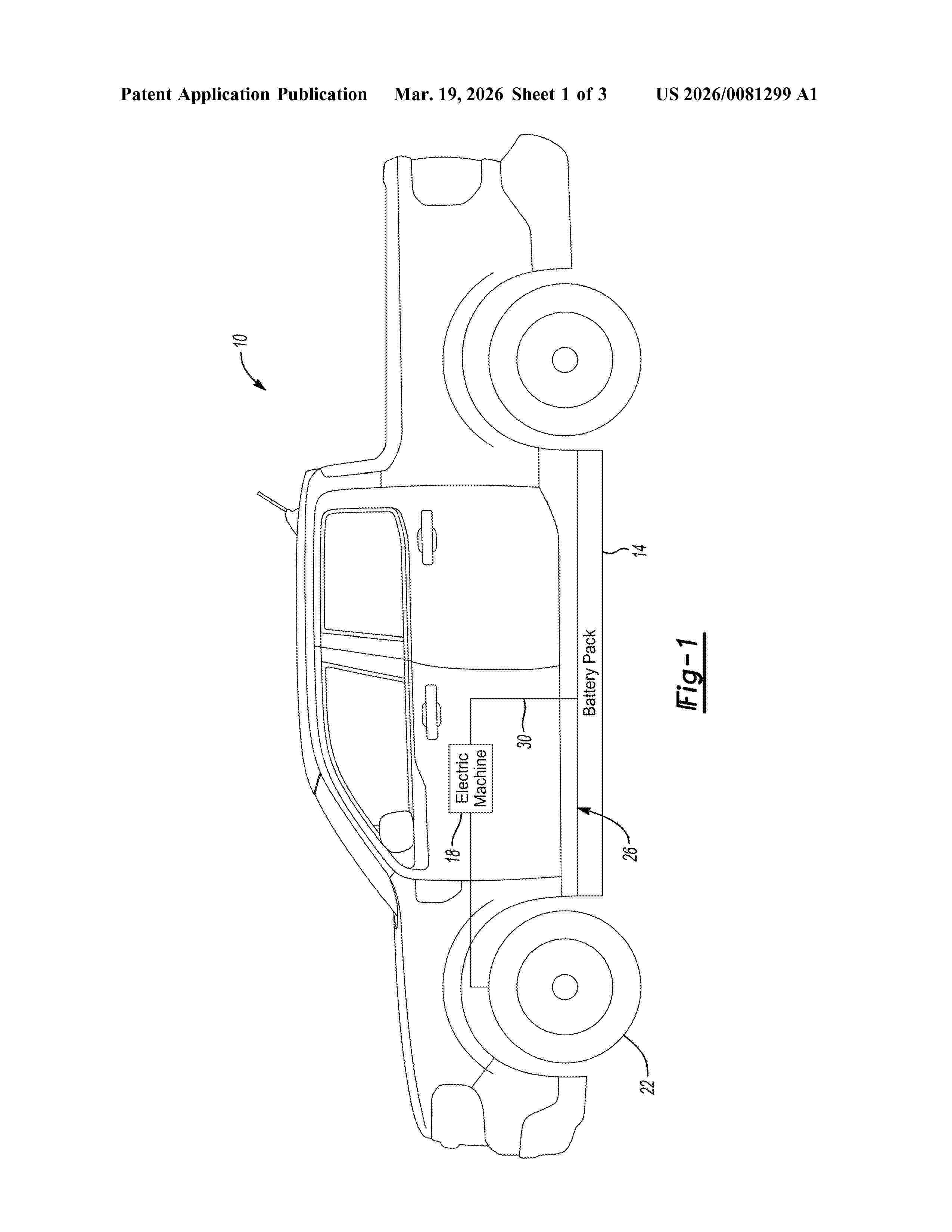
Resumen de: US20260081299A1
A traction battery pack assembly includes a first tier of cylindrical battery cells; and a second tier of cylindrical battery cells. The second tier is inverted relative to the first tier. Another traction battery pack assembly includes an enclosure assembly providing an interior area; a first plurality of cylindrical battery cells disposed on a first tier within the interior area; a second plurality of cylindrical battery cells disposed on a second tier within the interior area; and a busbar assembly sandwiched between the first tier and the second tier. The busbar assembly has a first side contacting first terminals of the first plurality of cylindrical battery cells. The busbar assembly has an opposite, second side contacting second terminals of the second plurality of cylindrical battery cells. A polarity of the first terminals is the same as a polarity of the second terminals.
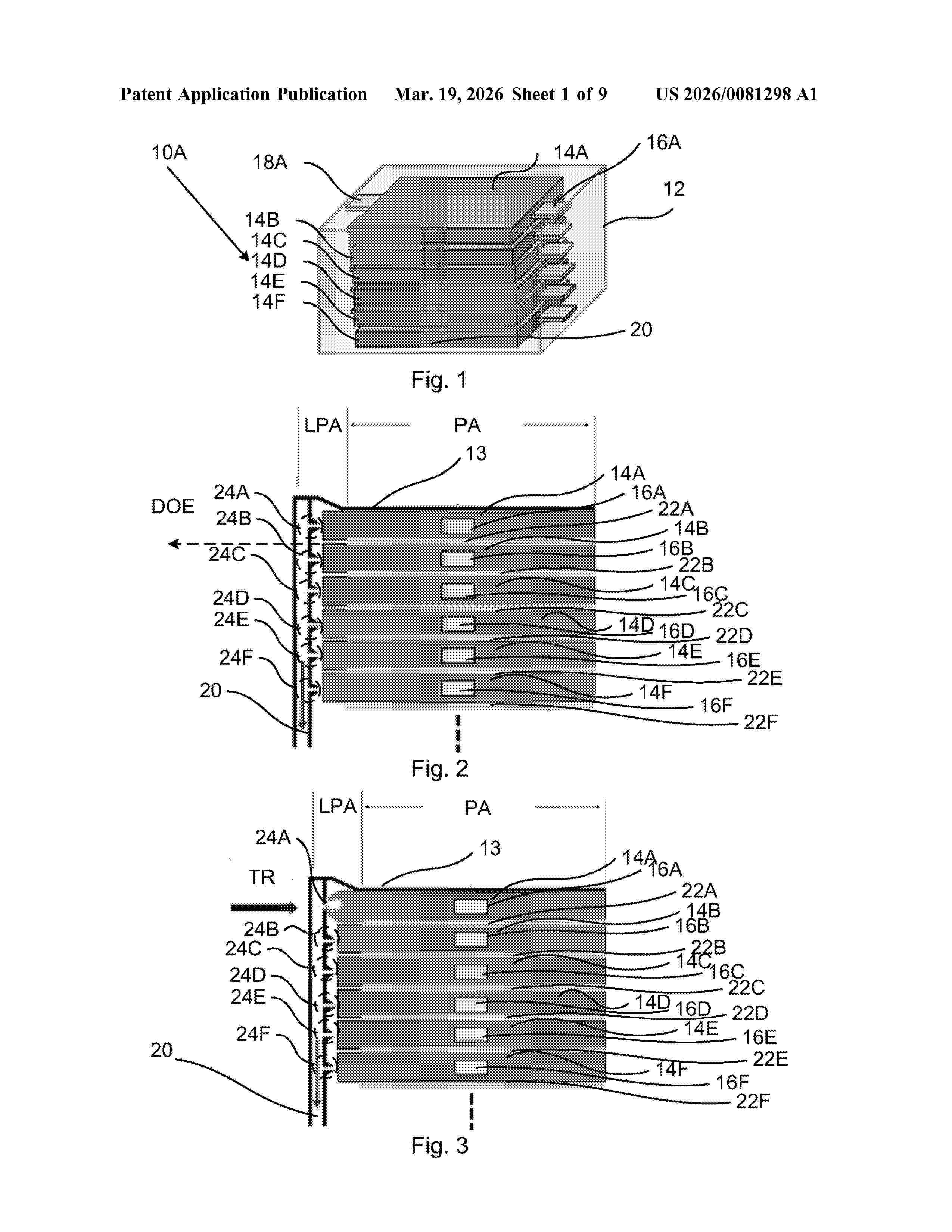
Resumen de: US20260081298A1
An electrochemical device comprises device comprising at least one pouch cell and a safety arrangement is described. The safety arrangement comprises a holding structure and at least one pouch piercing element. The at least one pouch piercing element is held adjacent to a corresponding pouch cell by the holding structure with a piercing end facing the corresponding pouch cell. Each flexible pouch cell is attached to the holding structure and is expandable in at least one direction, and one of the directions is towards the corresponding piercing element so that the piercing element pierces the pouch cell at the piercing end.
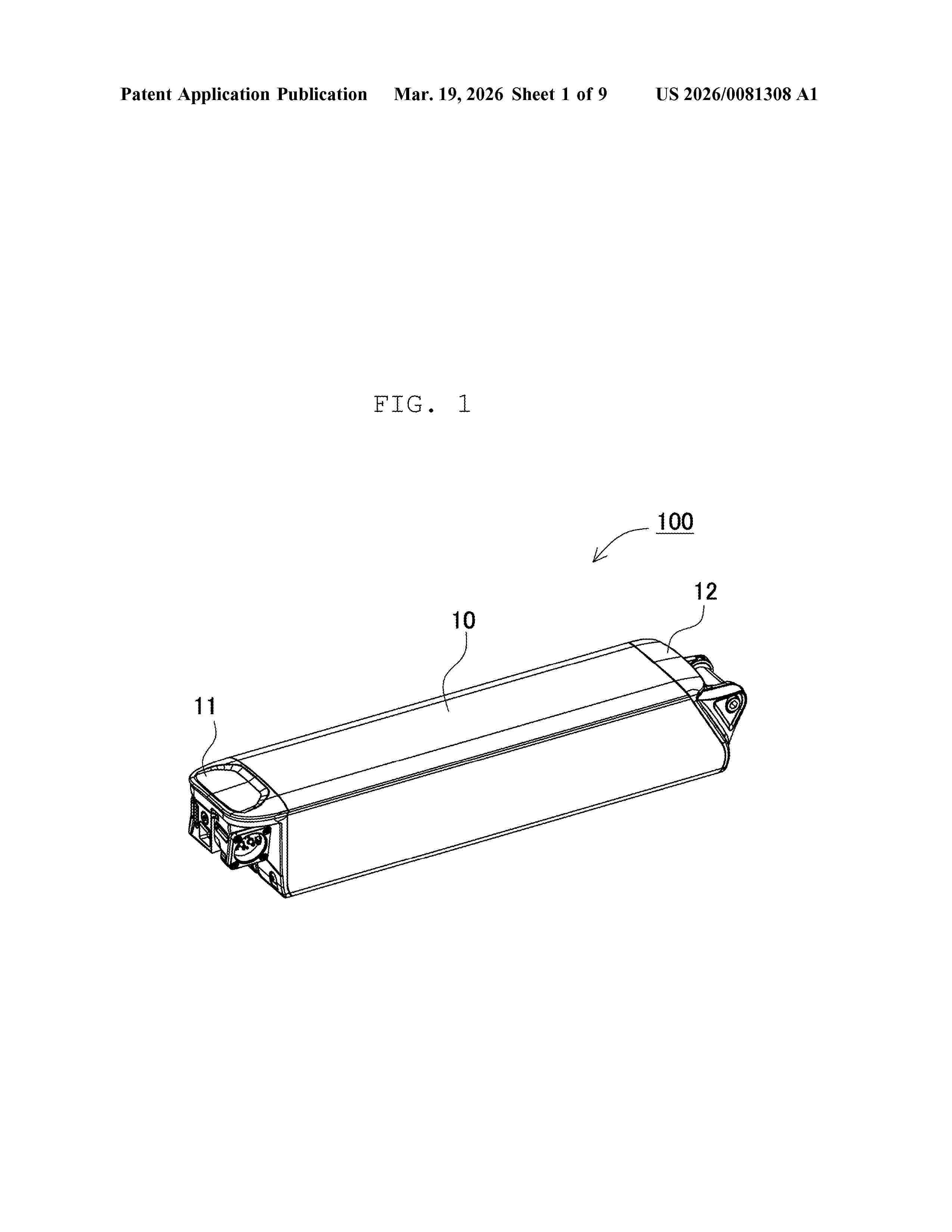
Resumen de: US20260081308A1
Spring back is suppressed with a simple configuration. An electric device includes lead plate including bent segment bent along bend line, circuit board electrically connected to bent segment of lead plate, and holder that holds lead plate. Holder includes holder portions that lock part of upper surfaces of bent segments. Holder portion is configured to abut on and hold the part of the upper surface of bent segment while the holder portion opposes a direction of spring back caused by bent segment of lead plate being bent along bend line. Circuit board includes connection region electrically connected to lead plate. Bent segment is electrically connected to connection region.
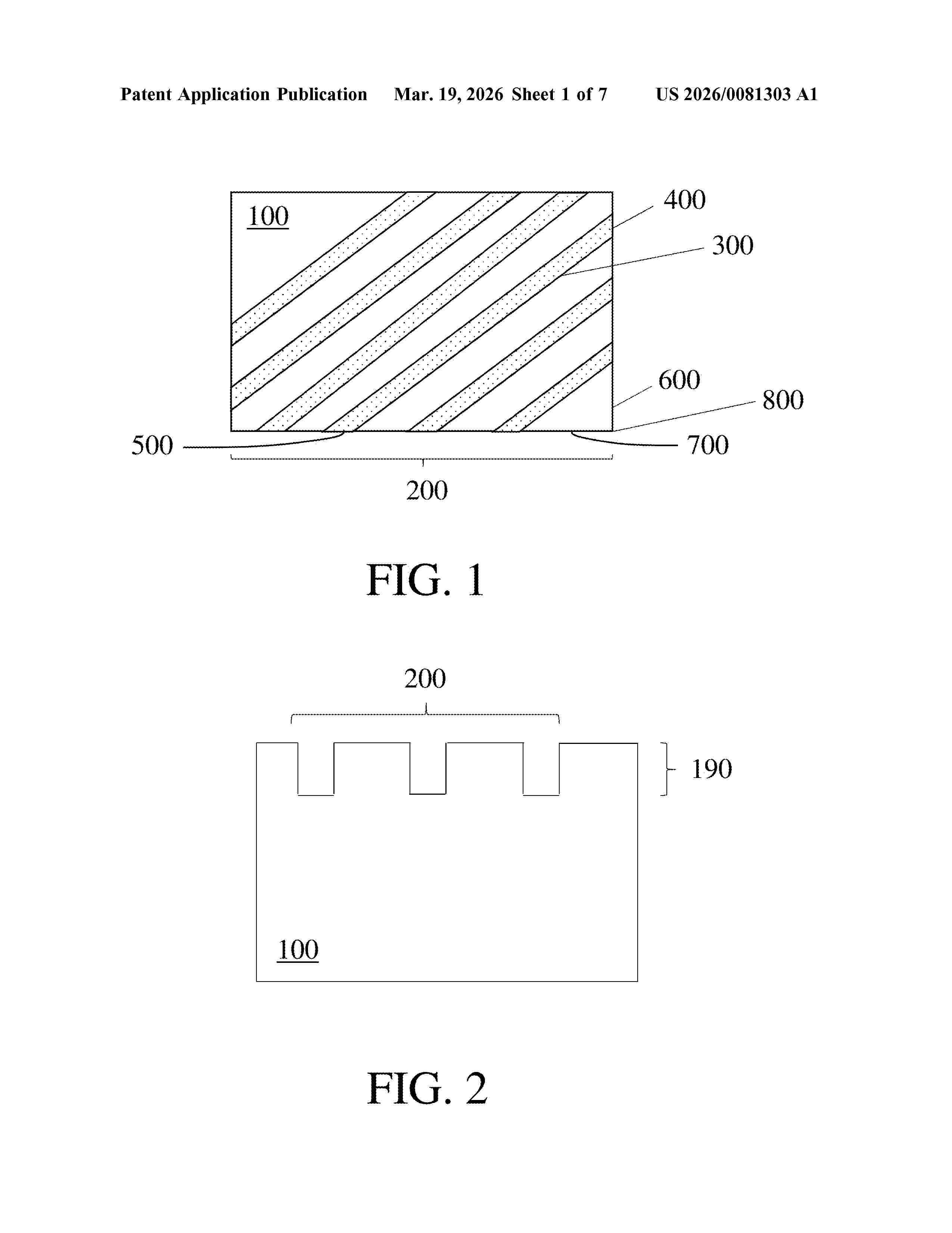
Resumen de: US20260081303A1
Battery separators comprising embossments are generally provided. The embossments may take the form of indentations formed in a surface of the battery separator, such as indentations formed by an embossing process. The embossments may comprise intersections with a first edge and a second edge of the battery separator, which may be the same or different.
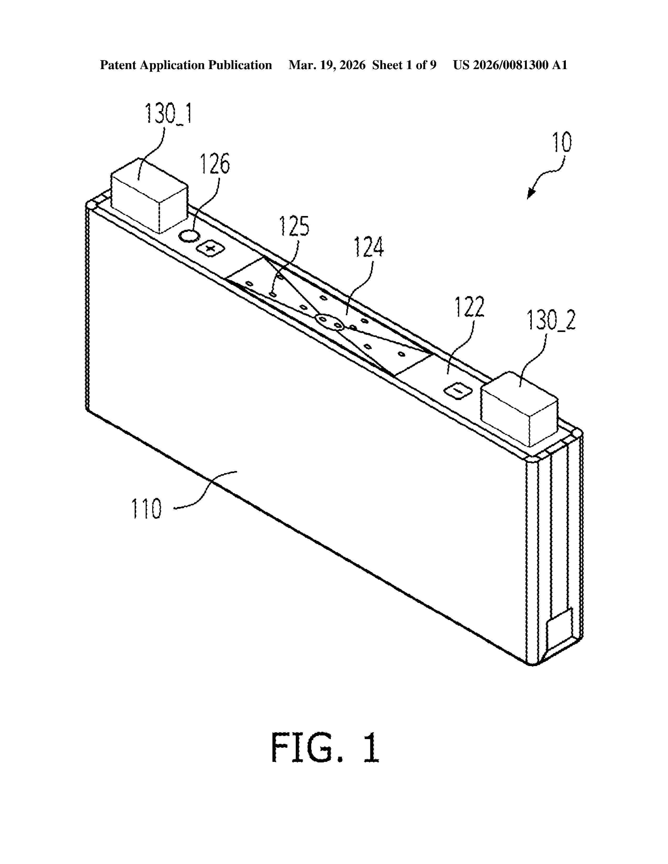
Resumen de: US20260081300A1
A battery assembly includes a case having an accommodation space therein, a plurality of cells in the accommodation space, the plurality of cells being arranged in a first direction, and an extinguishing tube in the accommodation space and extending along the first direction across the plurality of cells, the extinguishing tube being between two terminals exposed to outside of each of the plurality of cells, and the extinguishing tube being connectable to an extinguishing device.
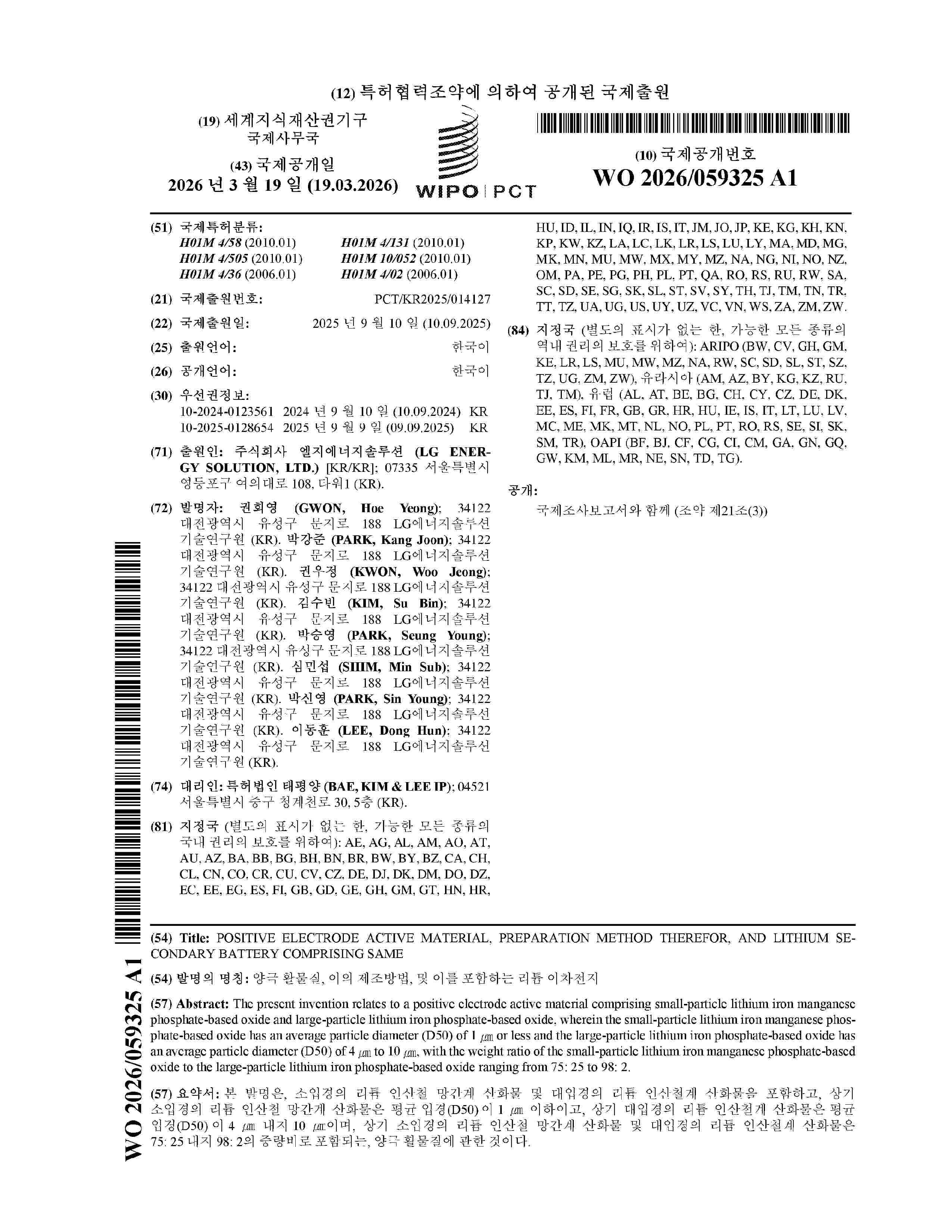
Resumen de: WO2026059325A1
The present invention relates to a positive electrode active material comprising small-particle lithium iron manganese phosphate-based oxide and large-particle lithium iron phosphate-based oxide, wherein the small-particle lithium iron manganese phosphate-based oxide has an average particle diameter (D50) of 1 ㎛ or less and the large-particle lithium iron phosphate-based oxide has an average particle diameter (D50) of 4 ㎛ to 10 ㎛, with the weight ratio of the small-particle lithium iron manganese phosphate-based oxide to the large-particle lithium iron phosphate-based oxide ranging from 75: 25 to 98: 2.
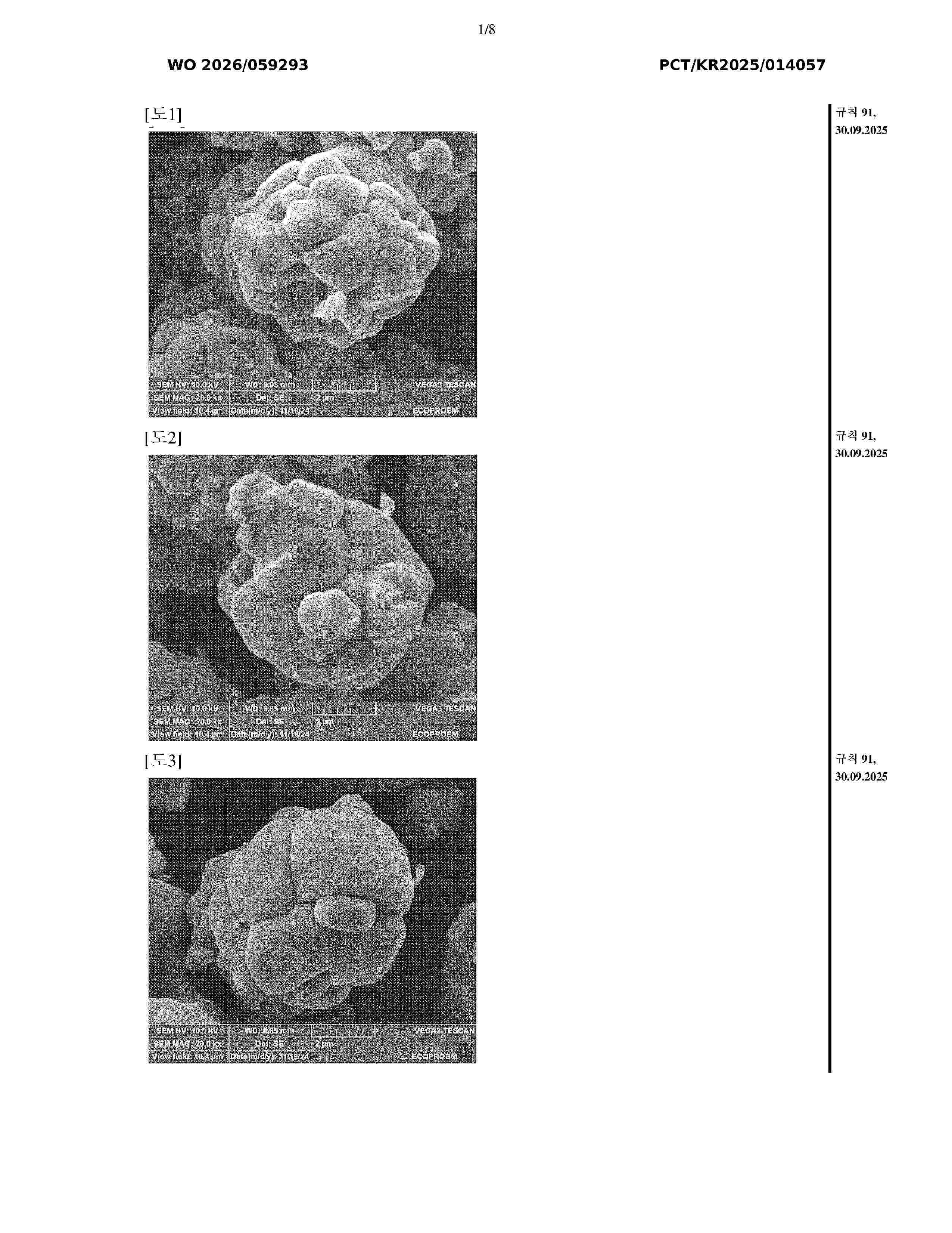
Resumen de: WO2026059293A1
The present invention relates to a positive electrode active material, and a lithium secondary battery using a positive electrode comprising the positive electrode active material. More specifically, the present invention relates to a positive electrode active material, and a lithium secondary battery using a positive electrode comprising the positive electrode active material, the material having a coating part that includes barium (Ba) and sulfur (S), which is present on at least a portion of the surface of a lithium transition metal oxide, so that lithium impurities can be reduced without washing, and enabling conductivity to be improved and side reactions with an electrolyte solution to be suppressed by means of the coating part including barium (Ba) and sulfur (S).
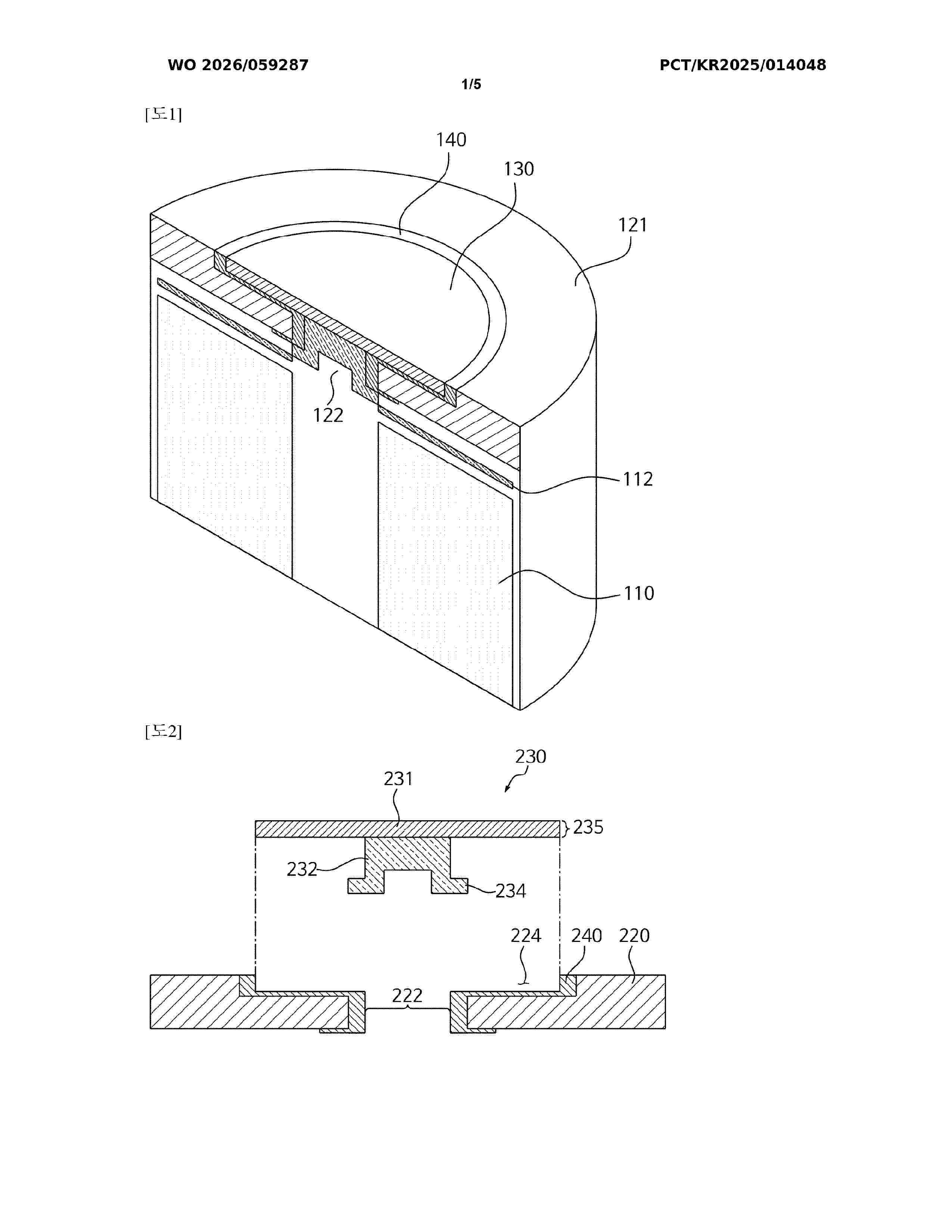
Resumen de: WO2026059287A1
The present disclosure provides a secondary battery and a method for manufacturing same. The secondary battery according to the present disclosure may comprise: an electrode assembly in which a first electrode, a separator, and a second electrode are sequentially stacked; a case accommodating the electrode assembly and having an electrolyte injection hole formed through one side surface thereof; and a rivet for sealing the electrolyte injection hole, wherein the rivet may comprise: a body portion in contact with the outer surface of an area on the case where the electrolyte injection hole is formed, and a leg portion in contact with the inner surface of the area on the case where the electrolyte injection hole is formed.
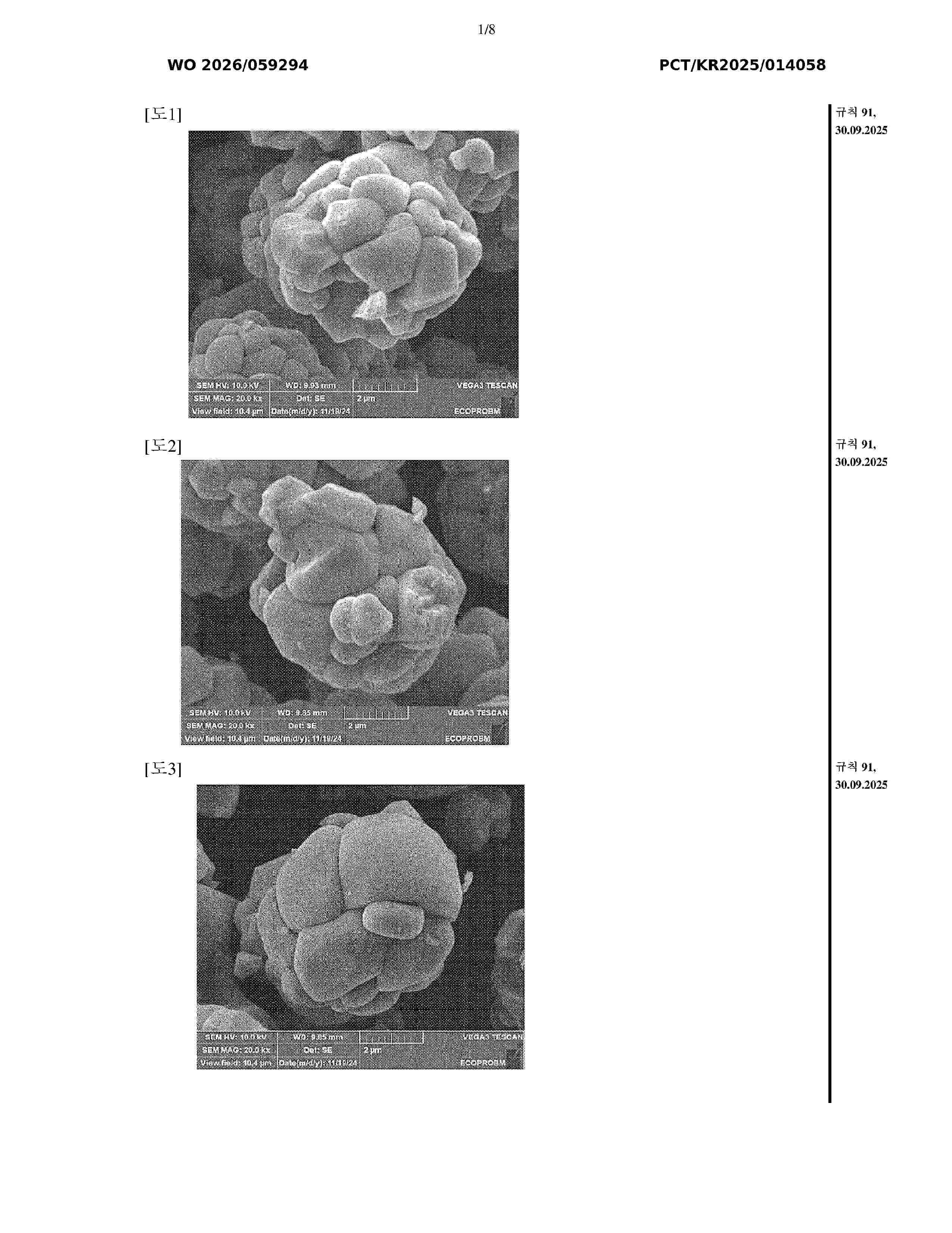
Resumen de: WO2026059294A1
The present invention relates to a cathode active material and a lithium secondary battery using a cathode including the cathode active material. More particularly, the present invention relates to: a cathode active material in which barium (Ba) and sulfur (S) are included at predetermined contents, enabling lithium impurities to be reduced without a washing process, and furthermore enabling improvement in the conductivity of the cathode active material to enhance capacity per unit volume; and a lithium secondary battery using a cathode including the cathode active material.
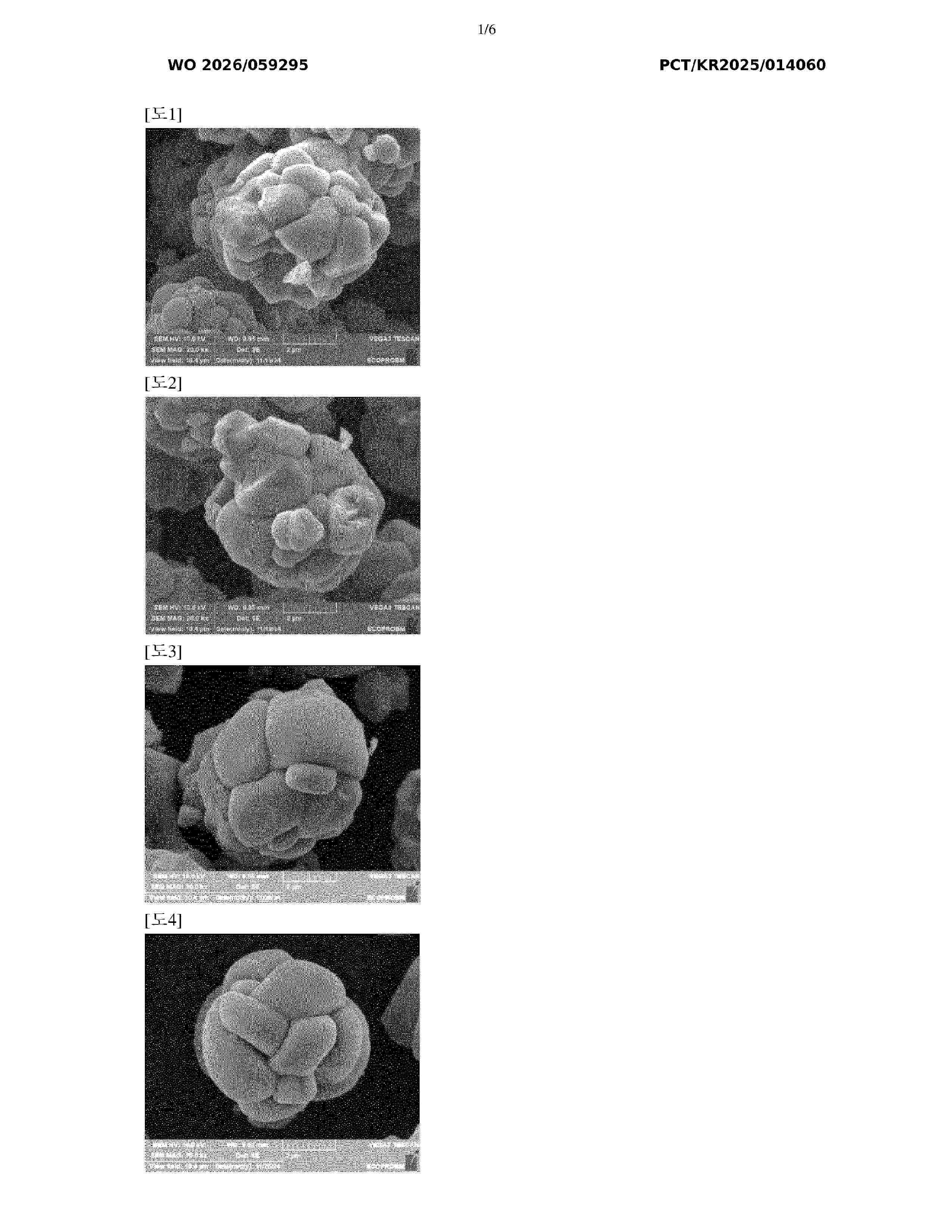
Resumen de: WO2026059295A1
The present invention relates to a positive electrode active material, and a lithium secondary battery using a positive electrode comprising the positive electrode active material. More specifically, the present invention relates to a positive electrode active material, and a lithium secondary battery using a positive electrode comprising the positive electrode active material, the material comprising barium (Ba) and sulfur (S) so that lithium impurities can be reduced without washing, and enabling the conductivity of the positive electrode active material to be improved, thereby causing the capacity per unit volume to increase.
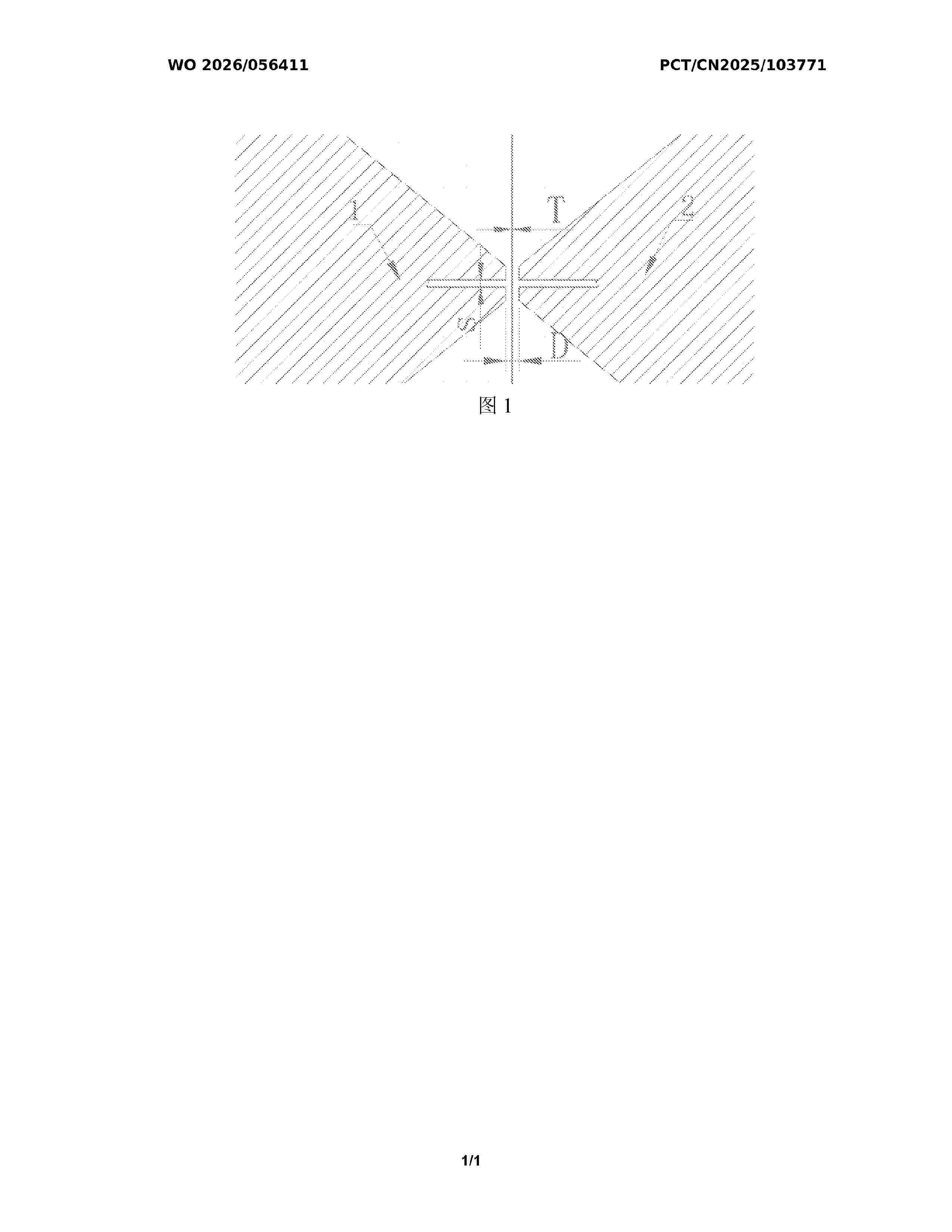
Resumen de: WO2026056411A1
A separator and a preparation method therefor and a use thereof. The preparation method comprises the following steps: S1: performing double-side coating on a substrate to obtain a first membrane material; and S2: performing phase inversion on the first membrane material to obtain a separator. The double-side coating is performed by means of two slit dies arranged opposite to each other, and during double-side coating of the substrate by means of the two slit dies, the distances between the substrate and the two slit dies are equal; and the opening degree of a die lip of a slit die is denoted as S, the thickness of the substrate is denoted as T, the sum of the spacings from the two slit dies to the substrate is denoted as D, and S, T and D satisfy the following relationship: 3S≤D-T≤55S. By adopting face-to-face coating with the two slit dies and limiting the relationship among the opening degree of the die lip of the slit die, the thickness of the substrate, and the sum of the spacings from the two slit dies to the substrate, the consistency of the thickness on two sides of the separator is ensured, and the thickness deviation of coatings on two sides of the prepared separator is reduced.
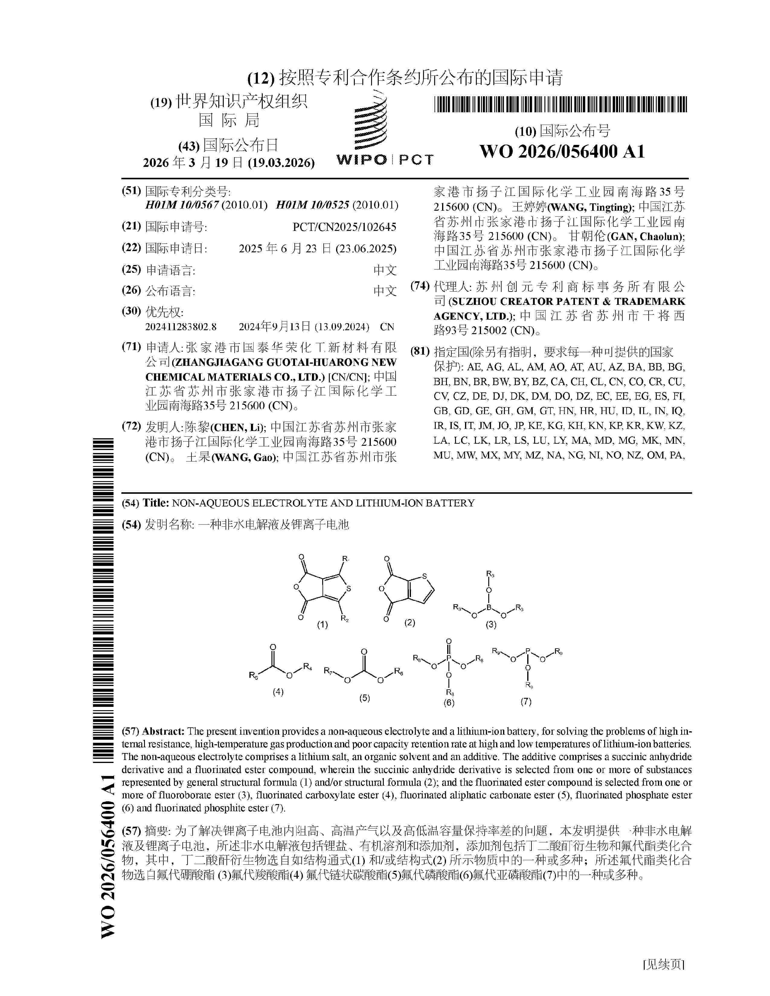
Resumen de: WO2026056400A1
The present invention provides a non-aqueous electrolyte and a lithium-ion battery, for solving the problems of high internal resistance, high-temperature gas production and poor capacity retention rate at high and low temperatures of lithium-ion batteries. The non-aqueous electrolyte comprises a lithium salt, an organic solvent and an additive. The additive comprises a succinic anhydride derivative and a fluorinated ester compound, wherein the succinic anhydride derivative is selected from one or more of substances represented by general structural formula (1) and/or structural formula (2); and the fluorinated ester compound is selected from one or more of fluoroborate ester (3), fluorinated carboxylate ester (4), fluorinated aliphatic carbonate ester (5), fluorinated phosphate ester (6) and fluorinated phosphite ester (7).
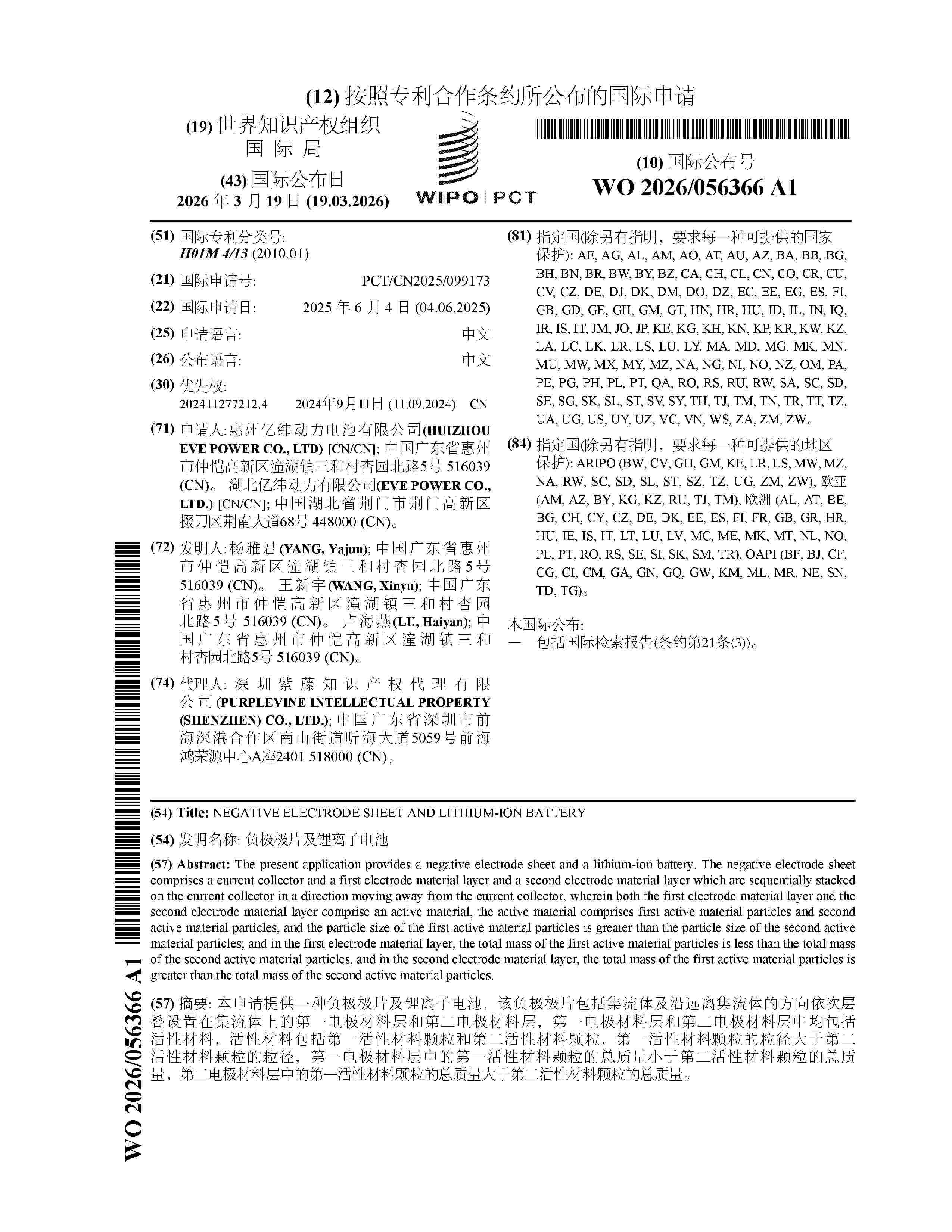
Resumen de: WO2026056366A1
The present application provides a negative electrode sheet and a lithium-ion battery. The negative electrode sheet comprises a current collector and a first electrode material layer and a second electrode material layer which are sequentially stacked on the current collector in a direction moving away from the current collector, wherein both the first electrode material layer and the second electrode material layer comprise an active material, the active material comprises first active material particles and second active material particles, and the particle size of the first active material particles is greater than the particle size of the second active material particles; and in the first electrode material layer, the total mass of the first active material particles is less than the total mass of the second active material particles, and in the second electrode material layer, the total mass of the first active material particles is greater than the total mass of the second active material particles.
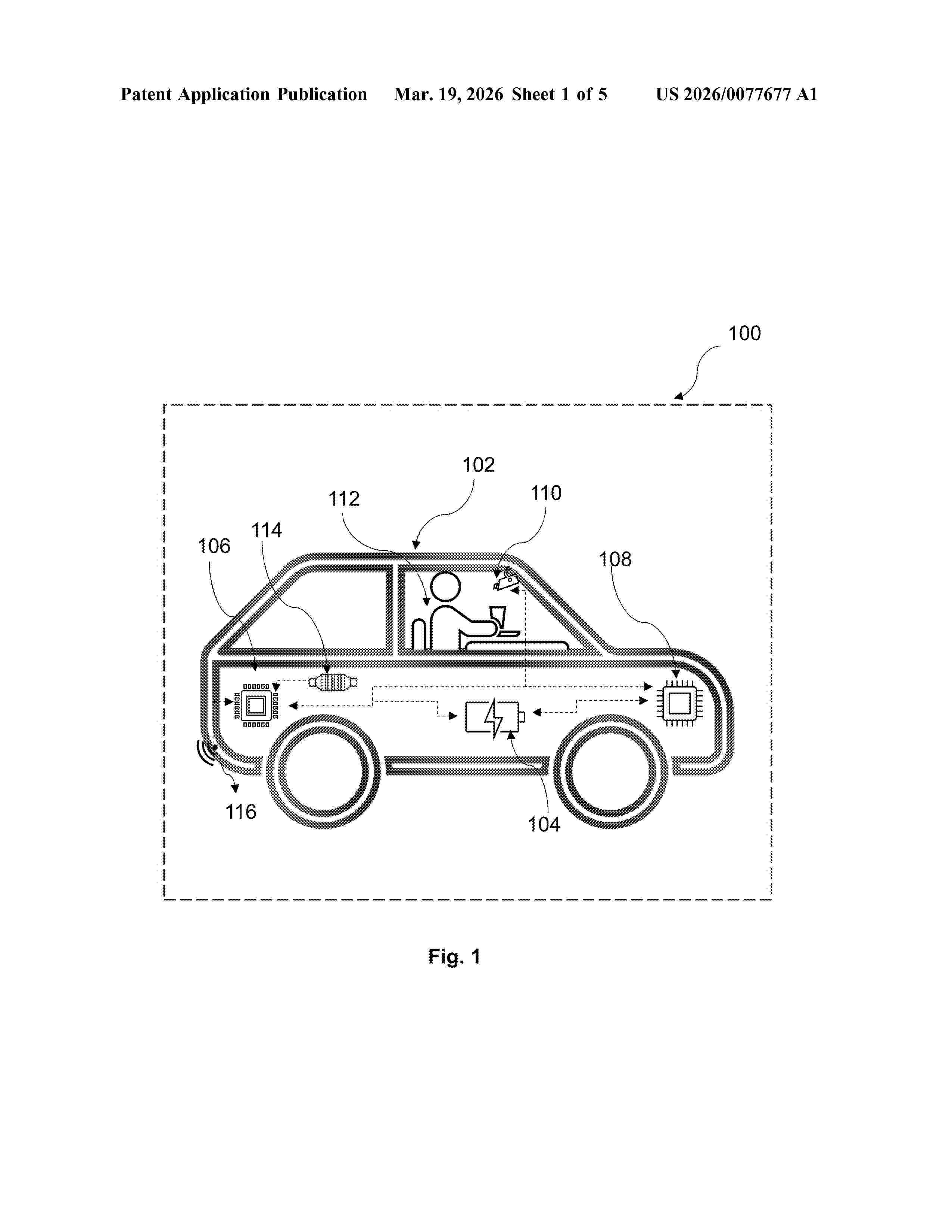
Resumen de: US20260077677A1
The present disclosure relates to a vehicle control system and method for SoX management. The vehicle control system comprises a control circuitry and a battery management system. The control circuitry determines an operational schedule of the vehicle and monitors at least one parameter of battery state. The battery management unit is communicatively coupled to the control circuitry. The battery management unit defines and implements an adaptive battery threshold window based on an operational schedule of the vehicle and the at least one parameter of battery state. The adaptative battery threshold window comprises multiple soft threshold values.
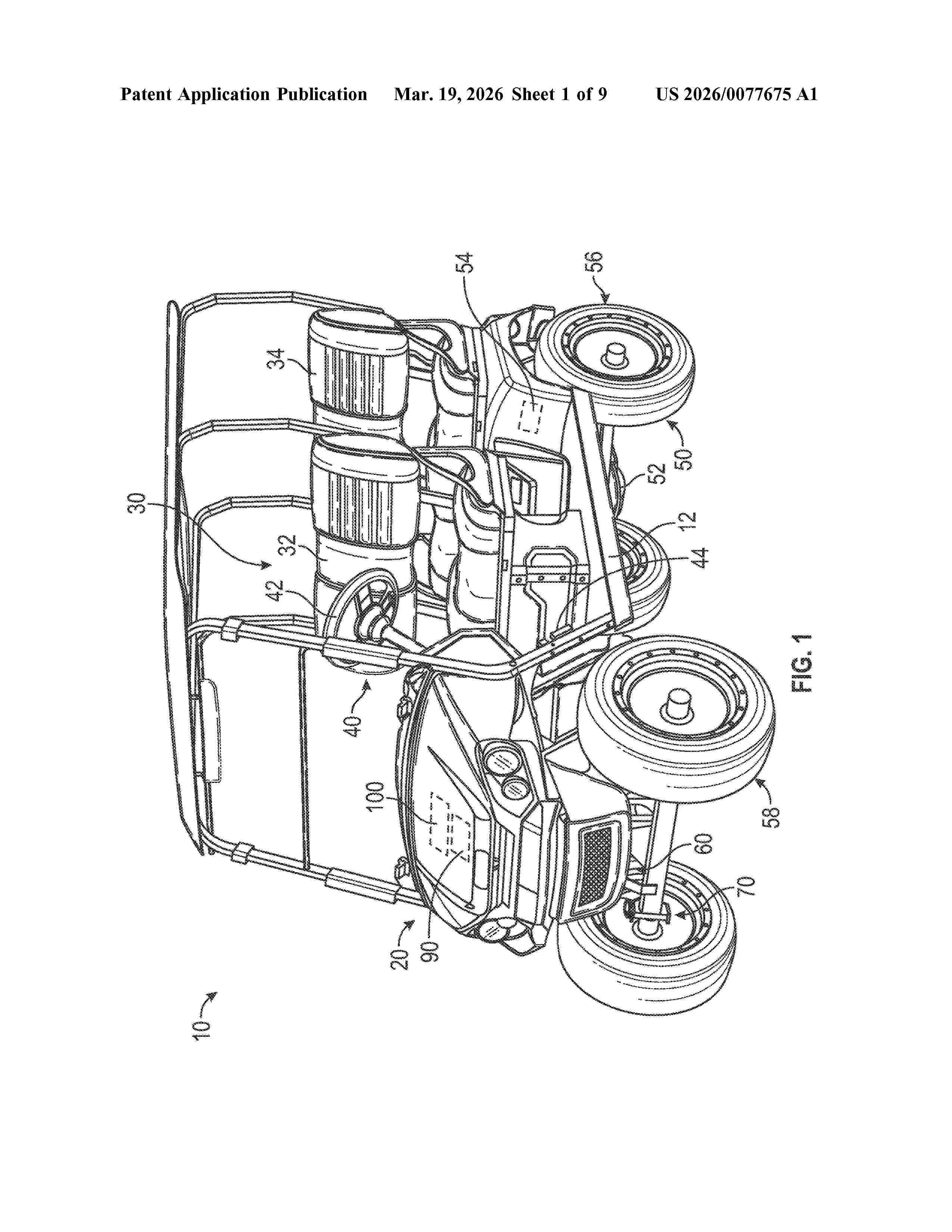
Resumen de: US20260077675A1
A golf vehicle includes a chassis, a battery pack supported by the chassis, and a plurality of sensors configured to facilitate detecting moisture. The battery pack is oriented relative to the chassis in a respective orientation of a plurality of possible orientations. The plurality of sensors are positioned at various locations about the battery pack. Each sensor is located at a respective point of the battery pack relative to a particular orientation. The vehicle control system is configured to acquire moisture signals from the sensors, and to determine at least one of the respective orientation of the battery pack or a severity of a presence of moisture within the battery pack based on the moisture signals.
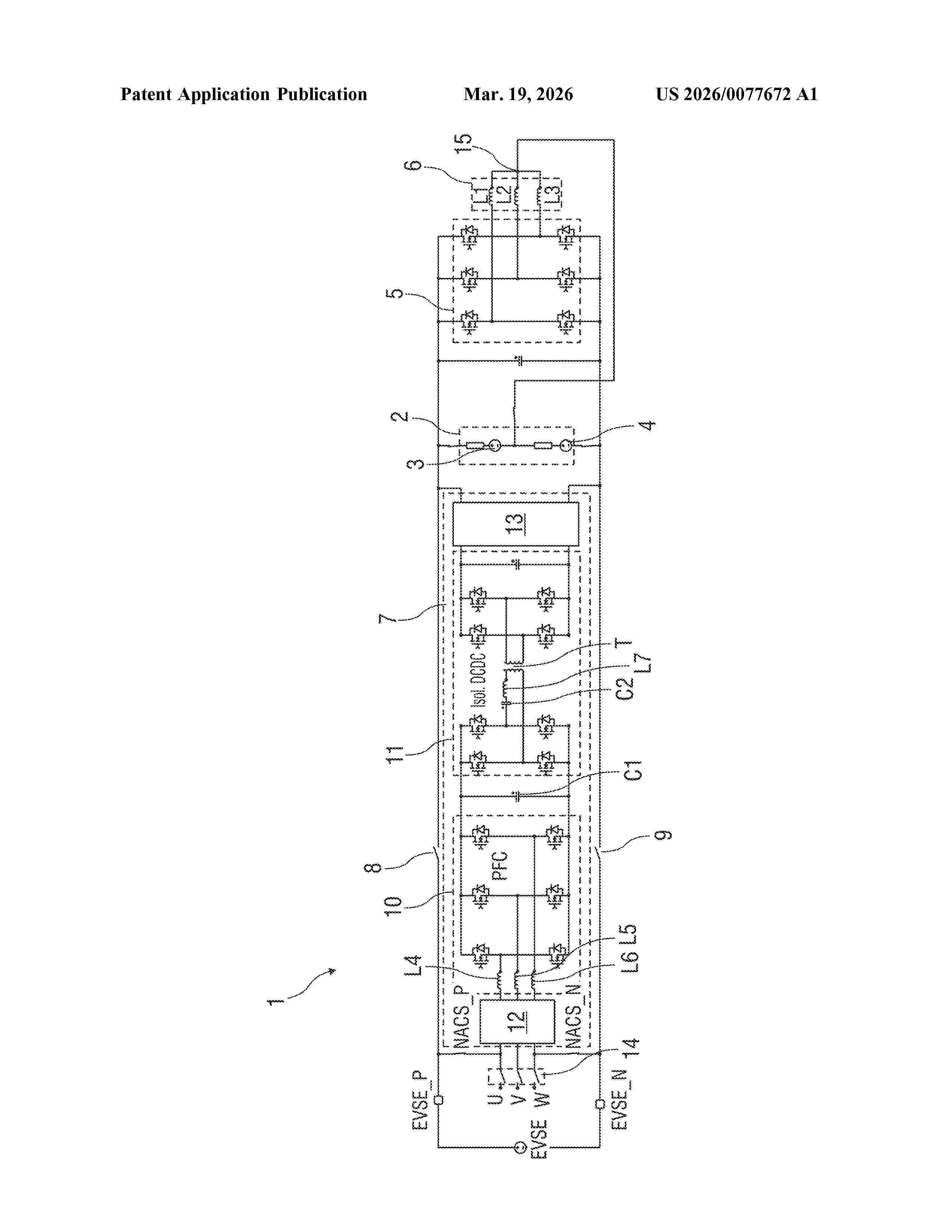
Resumen de: US20260077672A1
When charging a high-voltage battery at a DC charging station, a first step opens charging contactors, closes switching elements, and charges the high-voltage battery via the on-board charger and to transfer charge from one partial battery to the other partial battery or vice versa by an inverter. In a second step, when the high-voltage battery has been warmed up to a predetermined target temperature by the recharging process, operation of the inverter is stopped, the charging contactors are closed and in parallel with this is charged charging via the onboard charger and charged via the charging contactors, and the on-board charger is then deactivated and the charging process continues exclusively via the charging contactors.
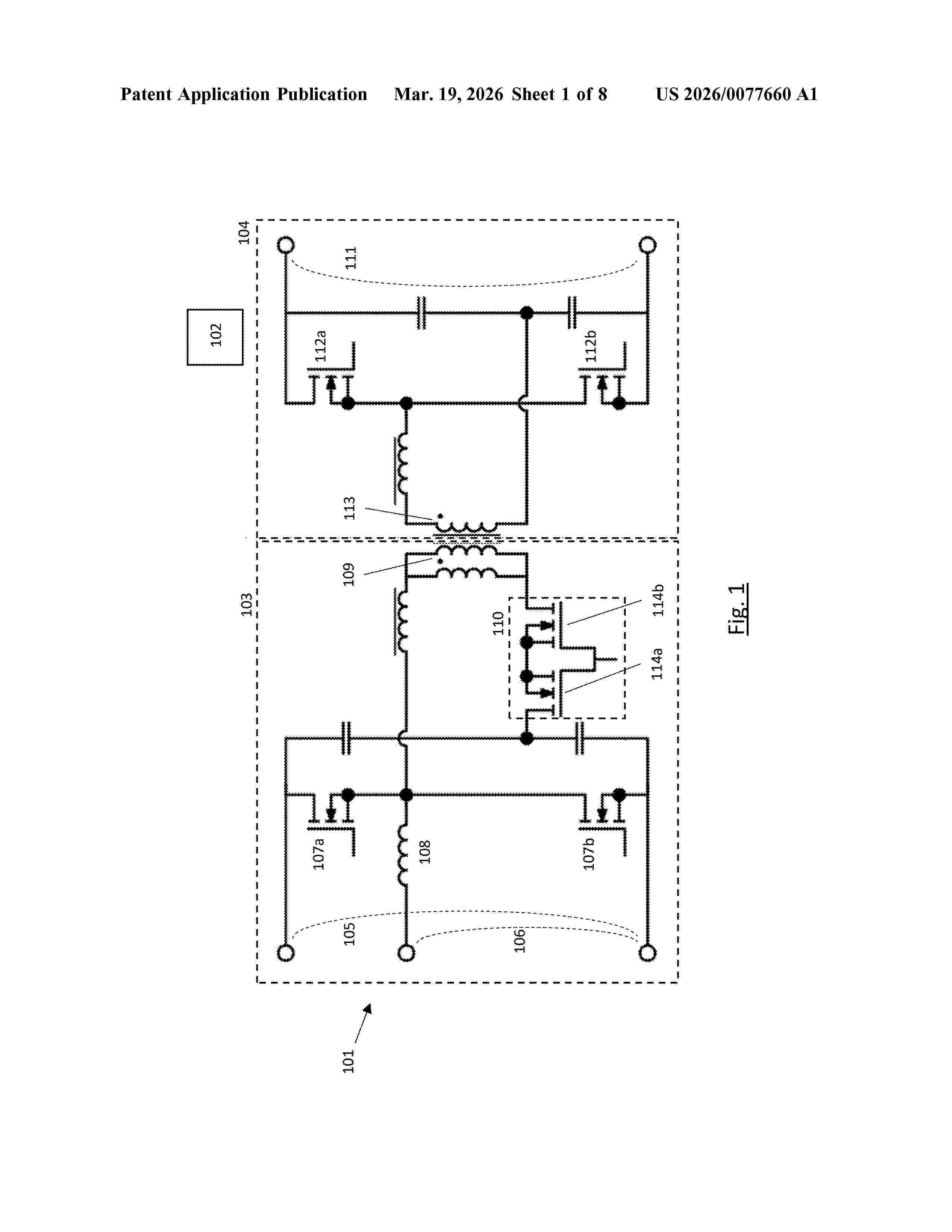
Resumen de: US20260077660A1
An isolated active bridge DC-DC power converter comprising a primary side, a secondary side, and a control unit. The primary side comprises one or more input power ports, a low voltage port, two primary-side switching elements for each of the one or more input power ports, a primary-side converter inductance for each of the one or more input power ports, and a primary-side transformer winding for each of the one or more input power ports. Each pair of primary-side switching elements and a respective primary-side converter inductance is arranged to form a half-bridge arrangement for bidirectionally converting power between a respective input power port and the low voltage port. The secondary side comprises a high voltage port, two secondary-side switching elements, and a secondary-side transformer winding magnetically coupled to the primary-side transformer winding. The control unit is configured to control the two primary-side switching elements and the two secondary-side switching elements for converting power between the primary-side ports and the secondary-side port.
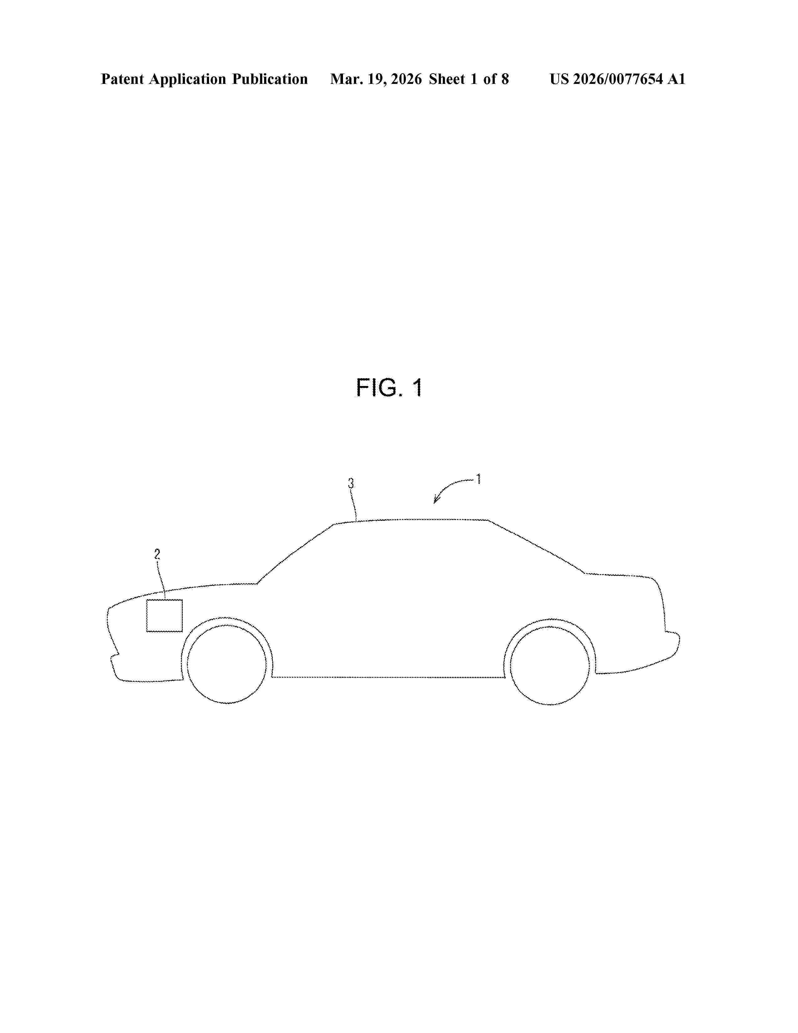
Resumen de: US20260077654A1
A battery management unit that manages an energy storage cell, the battery management unit including: a current sensor that measures a charge/discharge current in the energy storage cell; a first communication unit that communicates with a vehicle; and a management unit, in which the management unit executes: determination processing of detecting, by the current sensor, a pulse pattern occurring in the charge/discharge current in the energy storage cell, and determining whether or not the detected pulse pattern matches a predetermined pattern; and communication processing of communicating with the vehicle via the first communication unit when it is determined in the affirmative in the determination processing.
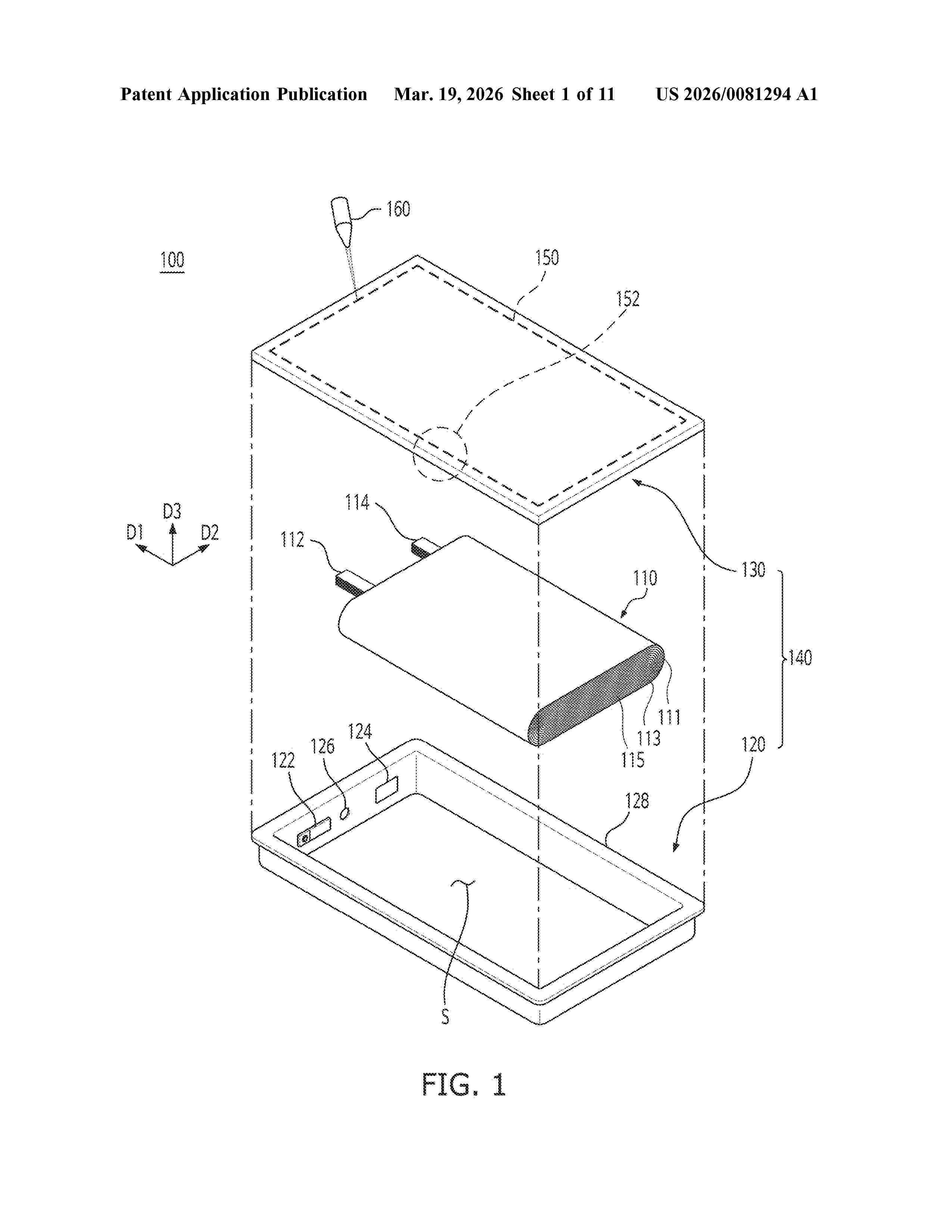
Resumen de: US20260081294A1
A case for a secondary battery, includes: a body including an accommodation portion having one opened end in a first direction to accommodate an electrode assembly, and a flange portion extending from the opened end in a direction different from the first direction; a cover welded to the flange portion to seal the opened end of the accommodation portion; and a welded portion of the flange portion and the cover. The welded portion includes a venting portion to be ruptured by an internal pressure of the accommodation portion sealed by the cover.
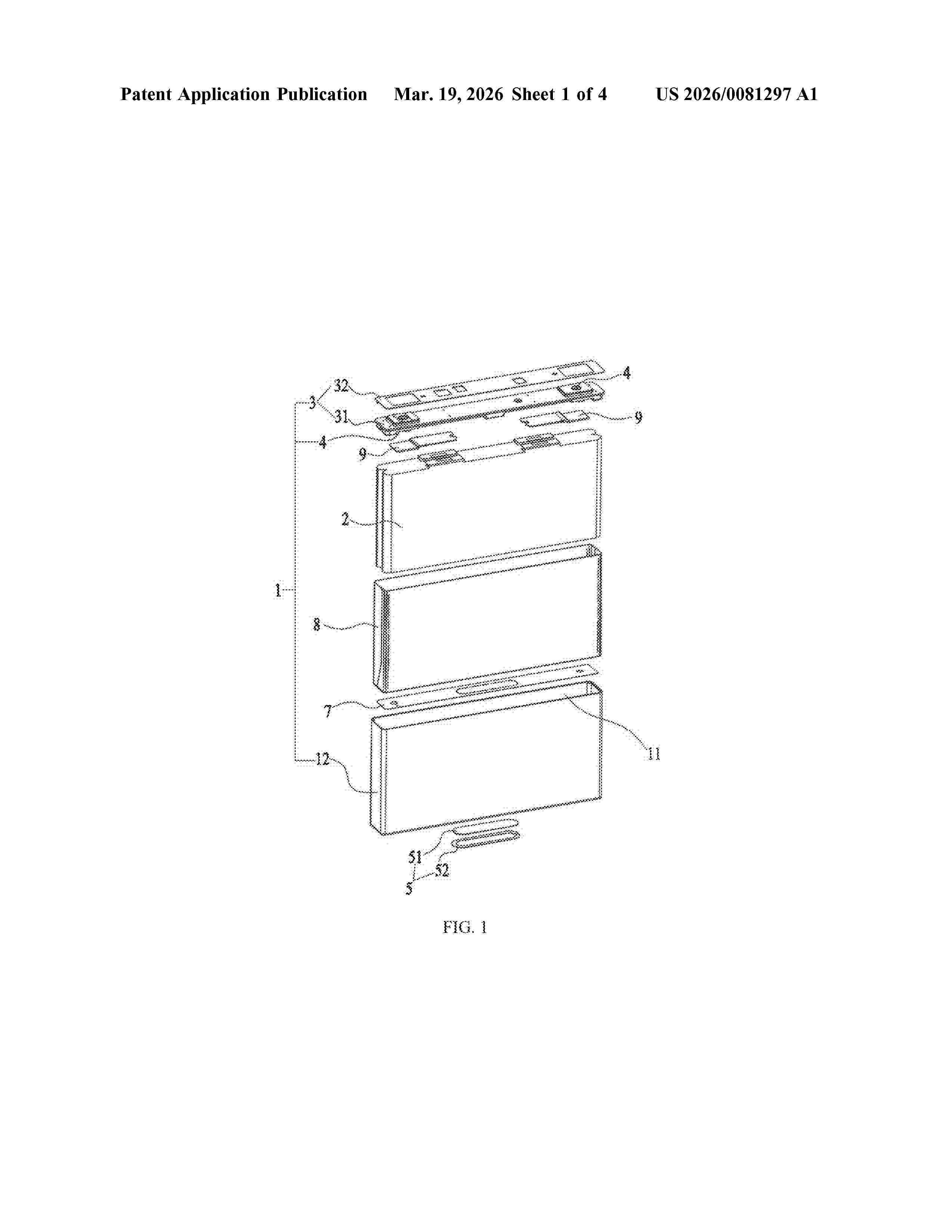
Resumen de: US20260081297A1
A battery cell includes a housing, a bare cell, and a pressure relief structure. The housing internally forms an accommodating cavity. The bare cell is accommodated in the accommodating cavity. The pressure relief structure is mounted on a first wall surface of the housing and configured to actuate when a pressure or temperature in the accommodating cavity reaches a threshold to communicate the accommodating cavity with an external space. The first wall surface forms a protruding structure protruding toward an interior of the accommodating cavity, and the protruding structure is configured to abut against the bare cell to form a flow channel between the bare cell and the first wall surface.
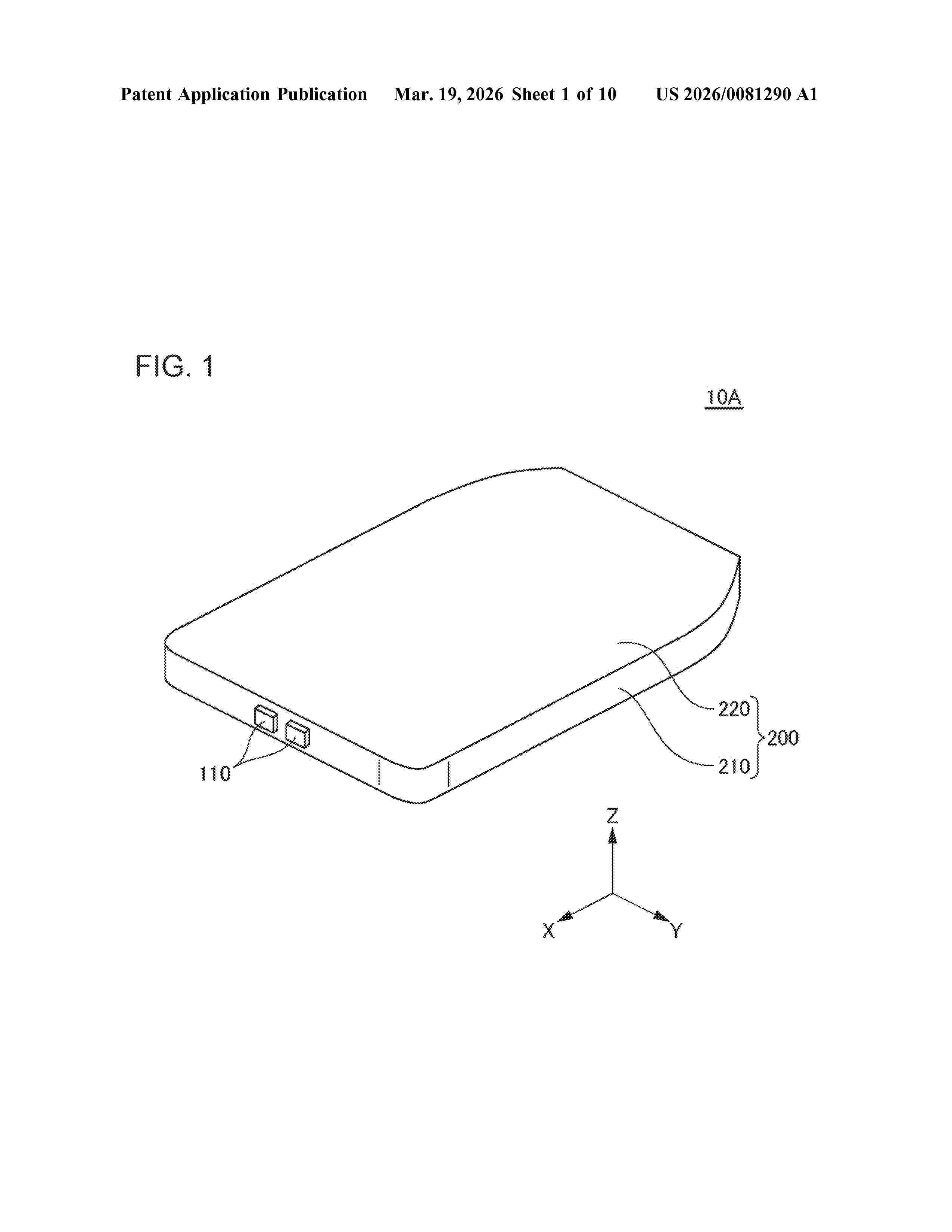
Resumen de: US20260081290A1
A battery pack (10A) includes a storage body (200) provided with a storage space (250) surrounded by a sealing member (230), a battery module (100) stored in the storage space (250), and a partition wall (214b) located between the battery module (100) and the sealing member (230). At least a portion of the partition wall (214b) is located at a higher elevation than an upper surface of the battery module (100).
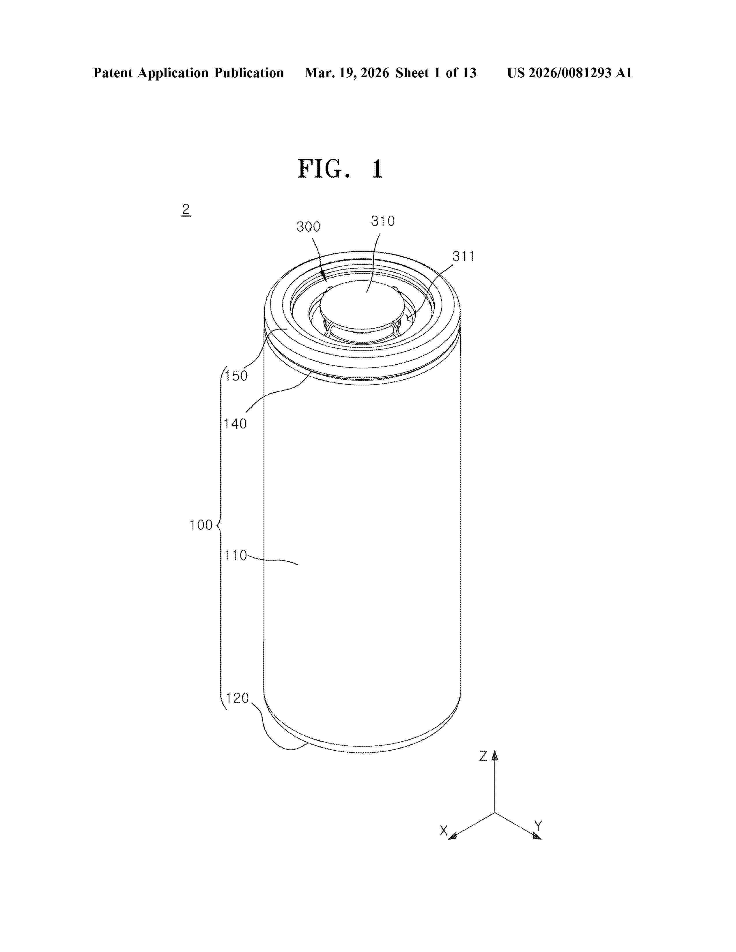
Resumen de: US20260081293A1
A secondary battery and a battery pack are disclosed. A secondary battery includes a case including an opening, an electrode assembly in the case, a cap up arranged in the opening, a cap down facing the cap up and connected to the electrode assembly, a vent plate between the cap up and the cap down and including a first vent surface and a second vent surface that are opposite to each other, a first notch formed concavely from the first vent surface toward the second vent surface, and a second notch formed concavely from the second vent surface toward the first vent surface.
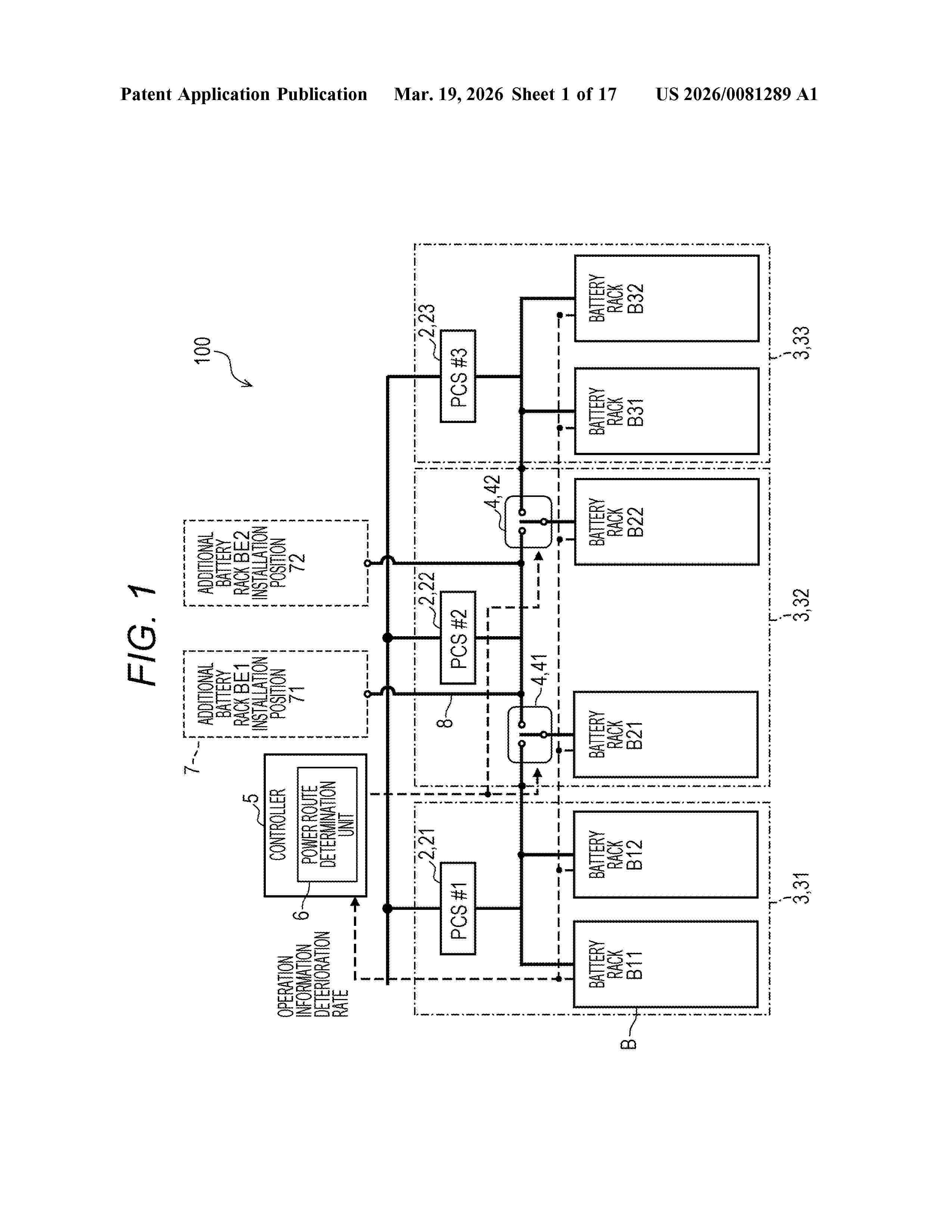
Resumen de: US20260081289A1
A secondary battery system is a secondary battery system including a battery bank including a battery rack including a plurality of battery cells connected in series and a power converter for charging and discharging a power system by one or a plurality of the battery racks connected in parallel, the secondary battery system includes a switch that enables the battery rack included in the battery bank to be switched to a power converter of another battery bank; and a controller that monitors a deterioration rate or an age of use of the battery rack and controls the power converter and the switch, in which the controller instructs the switch about a power converter to be connected based on the deterioration rate or the age of use of the battery rack.
Nº publicación: US20260081295A1 19/03/2026
Solicitante:
SAMSUNG SDI CO LTD [KR]
SAMSUNG SDI CO., LTD
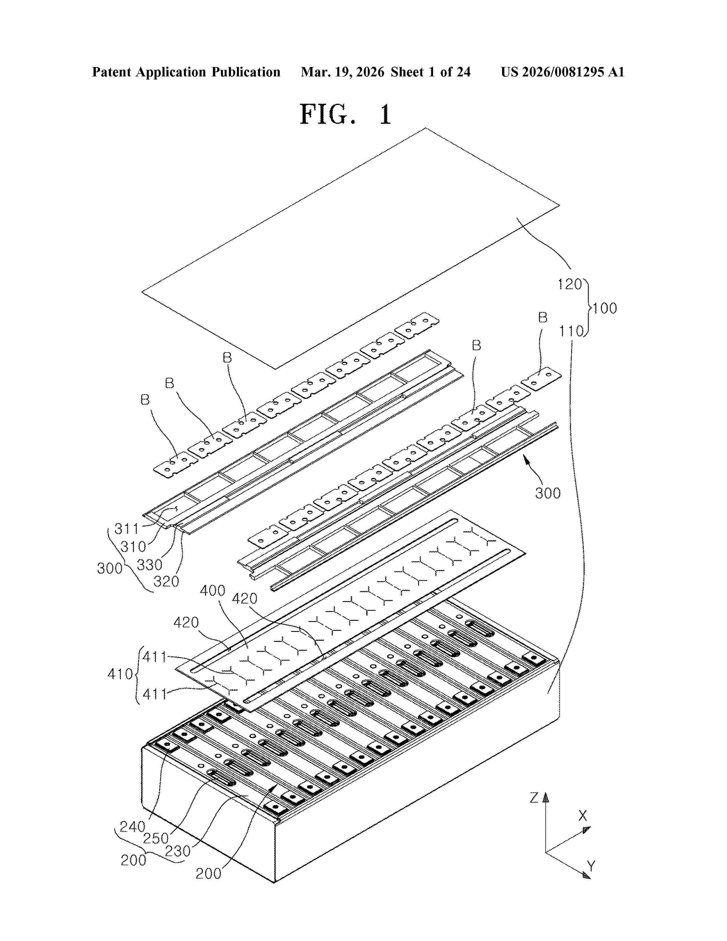
Resumen de: US20260081295A1
A battery module includes a housing, a plurality of battery cells, each of which includes an electrode assembly, a case accommodating the electrode assembly, a cap plate sealing the case, a pair of terminals protruding from the cap plate, and a vent between the terminals, the plurality of battery cells arranged in the housing in a first direction, a holder in the housing and facing the cap plate, and an inner sheet between the cap plate and the holder to cover the vent.
 BOPI
BOPI
 Sede Electrónica