Si deseas distinguir tus productos, servicios o ambos de los de otra empresa, es posible que necesites una marca o nombre comercial. Descubre qué son, en qué consiste su procedimiento de registro y qué implica.

Información sobre los plazos de presentación de solicitudes de transformación de marcas de la Unión Europea en marca nacional española. Más información


Si tienes un nuevo dispositivo, producto o procedimiento que resuelva un problema técnico o tenga una ventaja práctica, existen distintas formas de protegerlo en España y en otros países. Descubre cómo hacerlo.

¿Tu innovación reside en la estética, la ornamentación o la apariencia de tu producto? Protégela mediante un diseño industrial. Descubre qué derechos confiere el registro y cómo realizar la tramitación.

Las indicaciones geográficas protegen el nombre de un producto originario de una zona geográfica, a la cual le debe una determinada calidad, reputación u otra característica. Descubre qué son, en qué consiste su procedimiento de registro y qué beneficios conceden.

Las patentes publicadas en todo el mundo son una valiosa fuente de información científica, técnica y comercial.

Si eres emprendedor/a o una empresa y quieres potenciar y mejorar la rentabilidad de tu negocio protegiendo de forma adecuada los activos intangibles de tu organización, en este espacio encontrarás lo necesario.


 634
resultados
634
resultados
 Última actualización
01/04/2026 [08:11:00]
Última actualización
01/04/2026 [08:11:00]


 Resultados 375 a 400 de 634

Resumen de: CN121698202A
本发明公开了一种用于风电机组的电动升降装置,包括支撑框架、轿厢、驱动传动系统、导向组件和控制系统,支撑框架固定连接至机舱主机架,包括框架主体和导轨,驱动传动系统安装在框架主体上,包括驱动部分和与轿厢连接的传动部分,用于根据控制系统的指令使轿厢相对于支撑框架上升或下降,导向组件与轿厢固定连接,并且与导轨滚动连接。本方案通过全流程自动升降完成从塔底到机舱的最后一段,无需人工攀爬环节,大幅降低运维人员体力消耗,提升作业舒适度,降低作业风险;该装置能够显著提升运维效率,运维人员无需多次吊运沉重的工具,通过一次性搬运即可完成,节省维护时间。

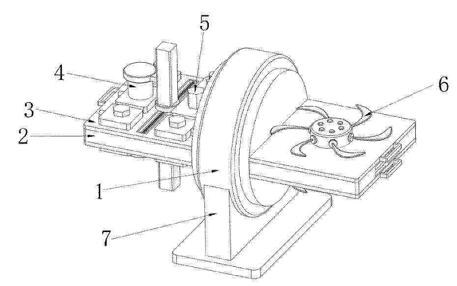
Resumen de: CN121701412A
本发明公开了风力发电机故障模拟装置,涉及风力发电机技术领域。包括主块以及安装在主块两端的放置机构,所述放置机构上安装有若干个放置板,若干个所述放置板上分别安装有螺栓紧固机构和桨叶转动机构。本发明通过设置的螺栓紧固机构用于模拟螺栓紧固性故障,通过设置的桨叶转动机构模拟可模拟散热风扇故障和风力发电机桨叶故障,其故障模拟均集中于主块上的放置机构,提高故障模拟的丰富度,通过放置机构使得放置板可旋转,便于工作人员同时进行不同故障的模拟学习,提高学习效率,且放置板可拆卸,利于工作人员根据螺栓紧固机构和桨叶转动机构使用的磨损情况对其进行更换或定期维护,提高使用时的灵活性。
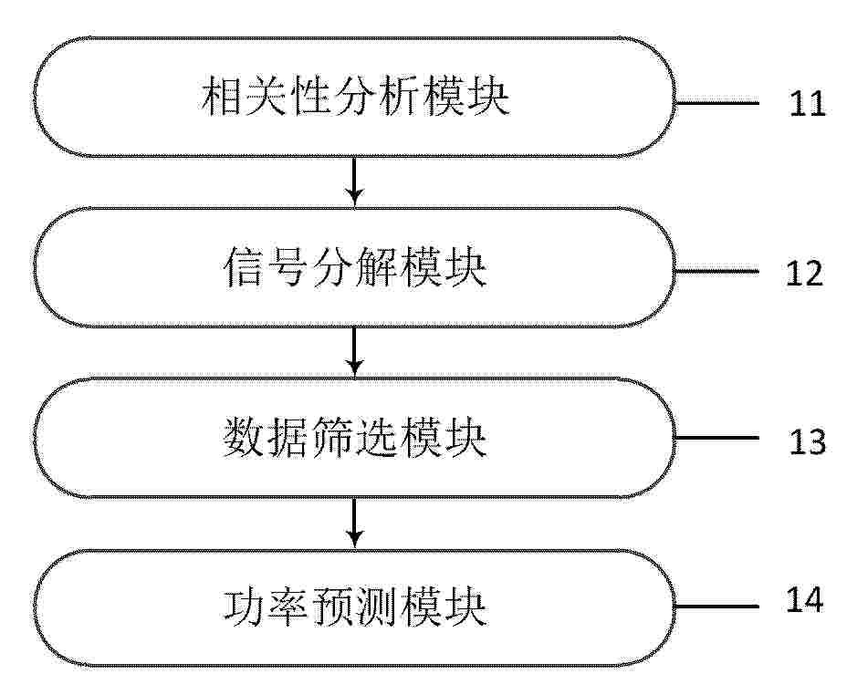
Resumen de: CN121710192A
本申请提供了融合信号分解与深度学习的风电功率预测系统及方法,涉及风电功率预测技术领域,所述系统包括:相关性分析模块对环境气象数据及风电功率数据进行相关性分析,信号分解模块将风电功率数据进行不少于二级信号分解,数据筛选模块采用最大信息系数算法分别计算各平稳子序列与所述相关气象变量之间的相关性,筛选输入特征数据,功率预测模块为每个平稳子序列构建深度学习预测模型,将平稳子序列及其对应的输入特征数据作为模型输入,并行对各分量进行功率值预测,将各分量的预测结果进行融合,输出风电功率预测结果。解决了现有技术中存在风电功率预测可靠性和准确性低的技术问题。达到了提高风电功率预测准确性和可靠性的技术效果。
Resumen de: CN224013833U
本实用新型公开了一种漂浮式风电基座,涉及风电基座技术领域,包括基座平台以及风电机组本体,风电机组本体固定安装于基座平台上,基座平台下方设置有浮座,浮座呈圆盘状,浮座内部中心设置有三角隔框,三角隔框内部设置有若干浮筒,基座平台与下方浮座之间设置有液压平衡机构以及若干缓冲机构。本实用新型由多个独立浮筒和连接结构组成,便于运输和组装,浮筒内部设有加强筋和隔舱结构,提升了整体强度和稳定性,配备液压平衡机构,可实时调整浮座与基座平台位置,确保平台在动态海洋环境中的水平稳定,缓冲机构有效吸收冲击和振动,基座采用高强度复合材料,减轻重量并具柔韧性,适应海浪冲击,安装效率提升,降低深水风电基座建设成本。
Resumen de: CN224016358U
一种用于风电混塔基础空腔悬挑部分的模板支撑结构,包括PVC管、上部支撑钢管、下部支撑钢管和底部钢板,风电混塔基础空腔悬挑部分下方的混凝土中设置PVC管,PVC管的底板固定底部钢板,PVC管内套入下部支撑钢管,下部支撑钢管的顶部承插上部支撑钢管,上部支撑钢管上安装可调节托撑,可调节托撑支撑在模板底部。本实用新型通过PVC管代替钢管,降低了传统支撑钢管的使用量,钢管可重复使用,减少了对新材料的需求,上下支撑钢管采用承插式支撑结构,拆模时只需将钢管分段取下,无需锯切钢管,简化了拆模操作,提高了工作效率;底部钢板不仅提高了支撑力,还有效地替代了传统的止水钢板,进一步提高了施工质量。
Resumen de: CN224018368U
本申请公开了一种风车灯,涉及灯具技术领域,为解决相关技术中风车灯的便携性较差和安装方式单一的问题而发明。该风车灯,包括灯柱、风车、光源和风力发电机,灯柱设有安装部,安装部用于与目标物体相连接;风车转动连接于灯柱的一端;光源连接于灯柱的另一端,光源用于照明;风力发电机设置于灯柱的内部,风力发电机的输入轴与风车连接,风力发电机的电源输出端与光源电连接。
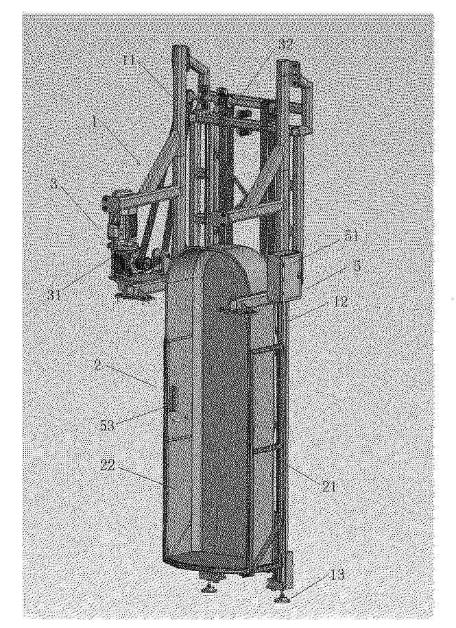
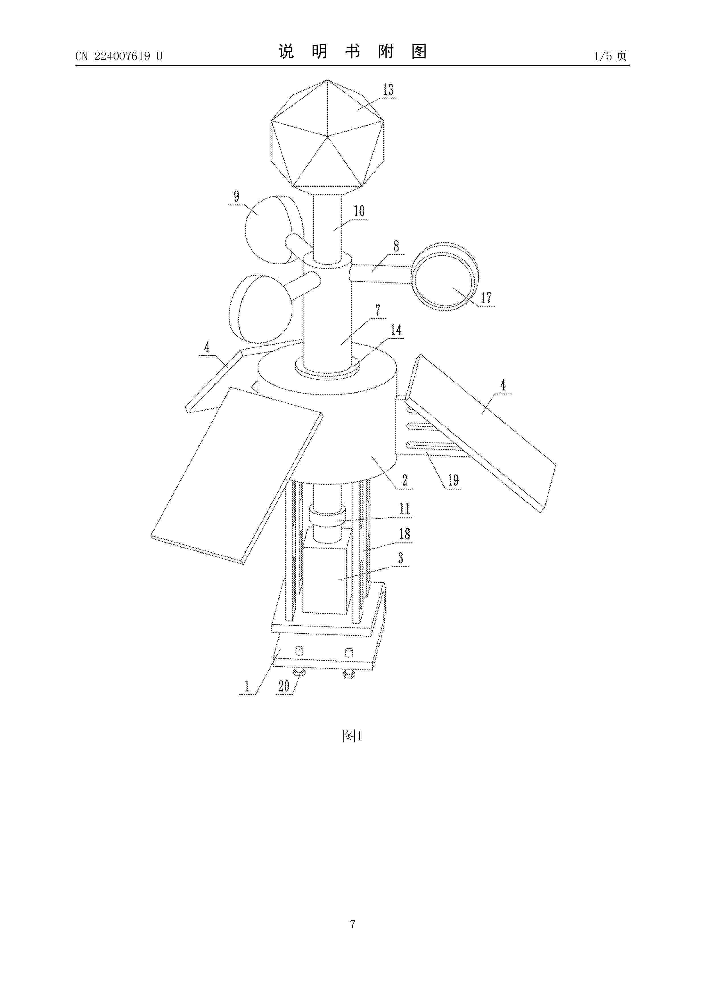
Resumen de: CN224007619U
本实用新型涉及电力防鸟害技术领域,具体涉及一种驱鸟器,包括基座和设置在基座上方的箱体,基座的上表面设置有电机,箱体的外周面上呈环形阵列有多个太阳能板;箱体内设置有蓄电池和发电机,发电机的输入轴连接有驱动组件,驱动组件包括套筒和连接杆,每根连接杆的一端固定至套筒上、另一端设置有风斗;套筒的内部穿设有与之同轴转动的转动轴,转动轴的底部与电机的输出轴相连接,转动轴的顶部设置有多面体,多面体的各个面上分别安装有反射镜片一。本实用新型通过在多面体的各个面上安装反射镜片一,扩大了驱鸟器的驱鸟范围,减小了盲区,并且通过发电机和太阳能板进行风光互补发电工作,将风能和光能转化为电能进行储存,降低了使用成本。
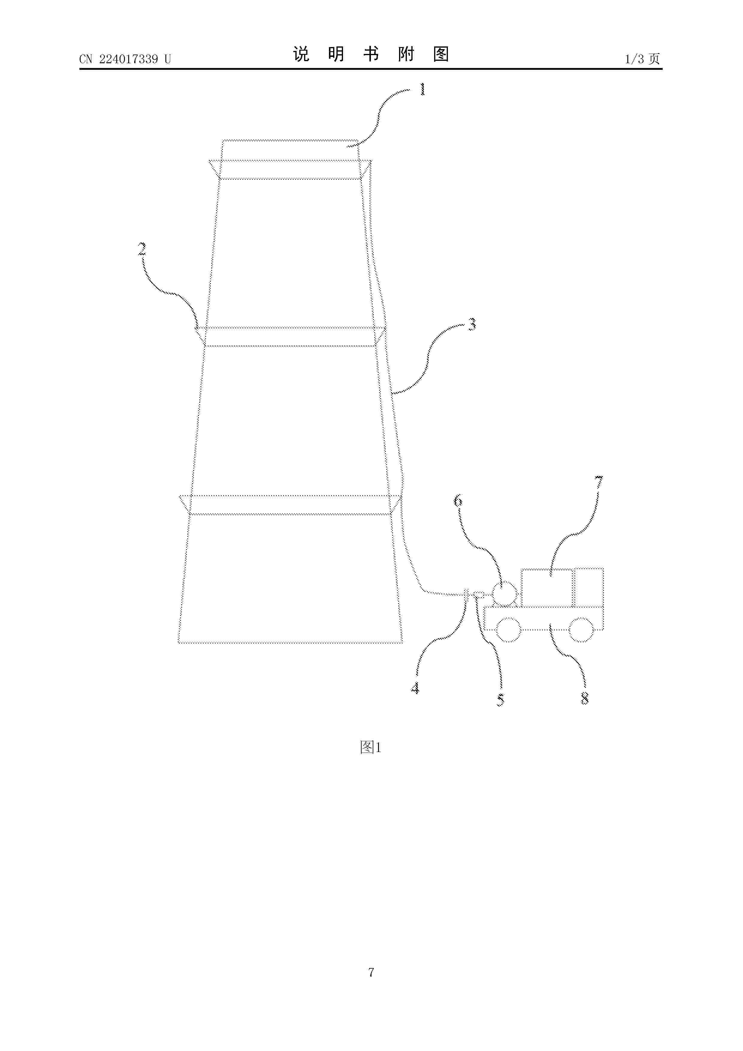
Resumen de: CN224017339U
本实用新型属于发电塔筒维护技术领域,具体涉及一种风电塔筒便捷冲洗清洁系统。该风电塔筒便捷冲洗清洁系统系统包括若干层清洗环、供水管、第二管接头、节流阀、水泵、水箱和运输车;其中所述清洗环用于设置在塔筒的外壁上;相邻层清洗环之间通过供水管连通,且各清洗环上设置有用于冲洗塔筒的喷头;所述水箱由运输车运载,且水箱依次通过水泵、节流阀、第二管接头和供水管向清洗环供水。清洗塔筒时只需将连接清洗环的供水给接通水源,通过水泵提供动力并利用摆动的喷头形成高压水雾完成塔筒表面清洁工作,无需复杂操作及登高作业,且清洗覆盖面积大、清洗时间短。
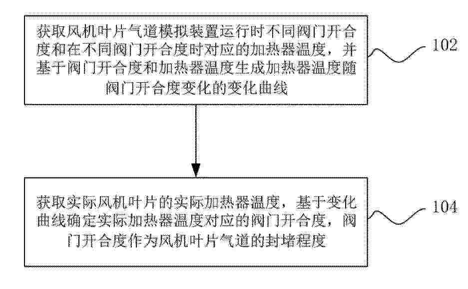
Resumen de: CN121701410A
本申请实施例提供一种风机叶片气道封堵程度的确定方法、确定装置、风机叶片及存储介质。方法包括:获取风机叶片气道模拟装置运行时不同阀门开合度和在不同阀门开合度时对应的加热器温度,并基于阀门开合度和加热器温度生成加热器温度随阀门开合度变化的变化曲线;获取实际风机叶片的实际加热器温度,基于变化曲线确定实际加热器温度对应的阀门开合度,阀门开合度作为风机叶片气道的封堵程度,通过建立加热器温度与阀门开合度之间的对应关系,将传统难以直接检测的气道封堵程度转化为可通过温度测量间接反演的参数,实现一种无需侵入式检测即可完成气道封堵程度评估的技术路径。
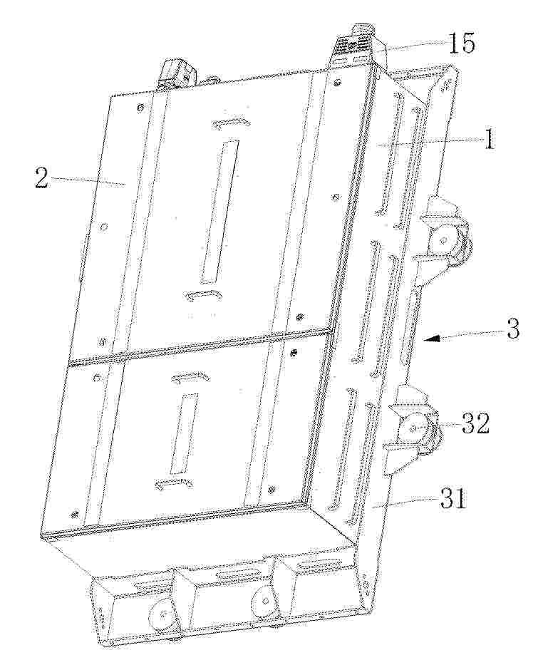
Resumen de: CN121711920A
本公开涉及一种风电变桨控制箱箱体及风电变桨控制箱,其中箱体包括主体框架及盖板,主体框架呈盒状,其中设置有至少一个隔板,以将主体框架的内腔分隔为至少两个子腔室,盖板设置有至少两个,用于盖设并密封子腔室。本公开的风电变桨控制箱箱体通过在主体框架的内腔中设置至少一个隔板以及多盖板,通过隔板将内腔分隔为至少两个子腔室,子腔室能够安装风电变桨控制箱箱体中的不同控制元件,在控制元件安装完成后则可以通过盖板盖设并密封子腔室。当子腔室中的控制元件出现损坏时,工作人员则可以根据元件的位置,打开其对应的子腔室的盖板进行检修,避免拆卸体积较大的盖板费时费力,还容易在拆卸和安装的过程中造成盖板的损坏。
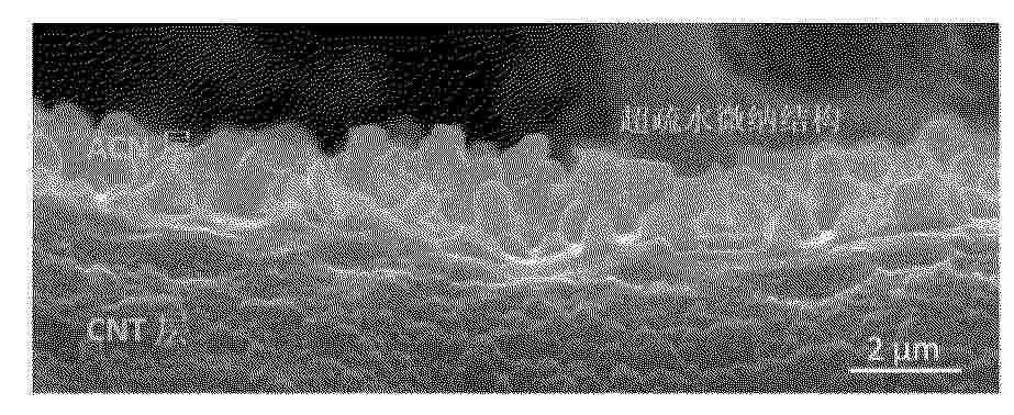
Resumen de: CN121700359A
本申请公开了一种基于超疏水非晶碳/碳纳米管防除冰涂层及其应用,涉及防除冰技术领域,包括耐高温基底以及形成于所述基底上的复合功能层;所述复合功能层为包含非晶碳、碳纳米管和石墨烯的三元复合结构;所述三元复合结构具有微纳米级粗糙表面;所述涂层兼具光热转换性能与电热转换性能;被动防冰与主动除冰机制协同作用,显著降低能耗,提高环境适应性。该涂层尤其适用于风力发电机叶片等设备的全天候防除冰保护,具有高效、耐久和低能耗的优点,为风力发电机叶片等设备提供了高效、持久的全天候防护解决方案。
Resumen de: CN121701415A
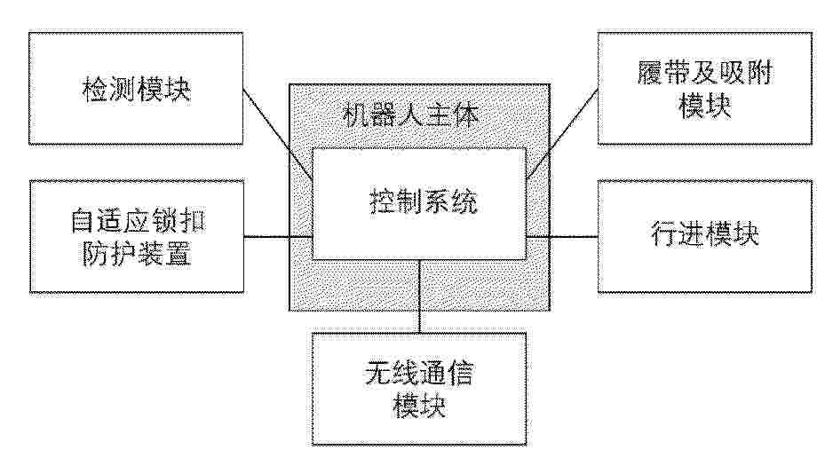
本发明涉及一种带自适应锁扣装置的风机叶片检测吸附式机器人,属于风机运维检测设备技术领域,包括机器人主体、设置在所述机器人主体侧部的行进模块和自适应锁扣防护装置、设置在所述行进模块底部的吸附模块、设置在所述机器人主体底部的检测模块、设置在所述机器人主体上部的无线通信模块以及设置在所述机器人主体内部的集成电源单元、控制单元及信号传输单元;本发明通过机器人主体、履带及吸附装置、行进模块、检测模块、自适应锁扣装置、控制系统及防护模块,各模块协同工作,实现风机叶片的高效、安全、稳定检测,解决现有吸附式机器人吸附稳定性差、无自适应锁止机构、防护性能不足的技术痛点。
Resumen de: CN224017334U
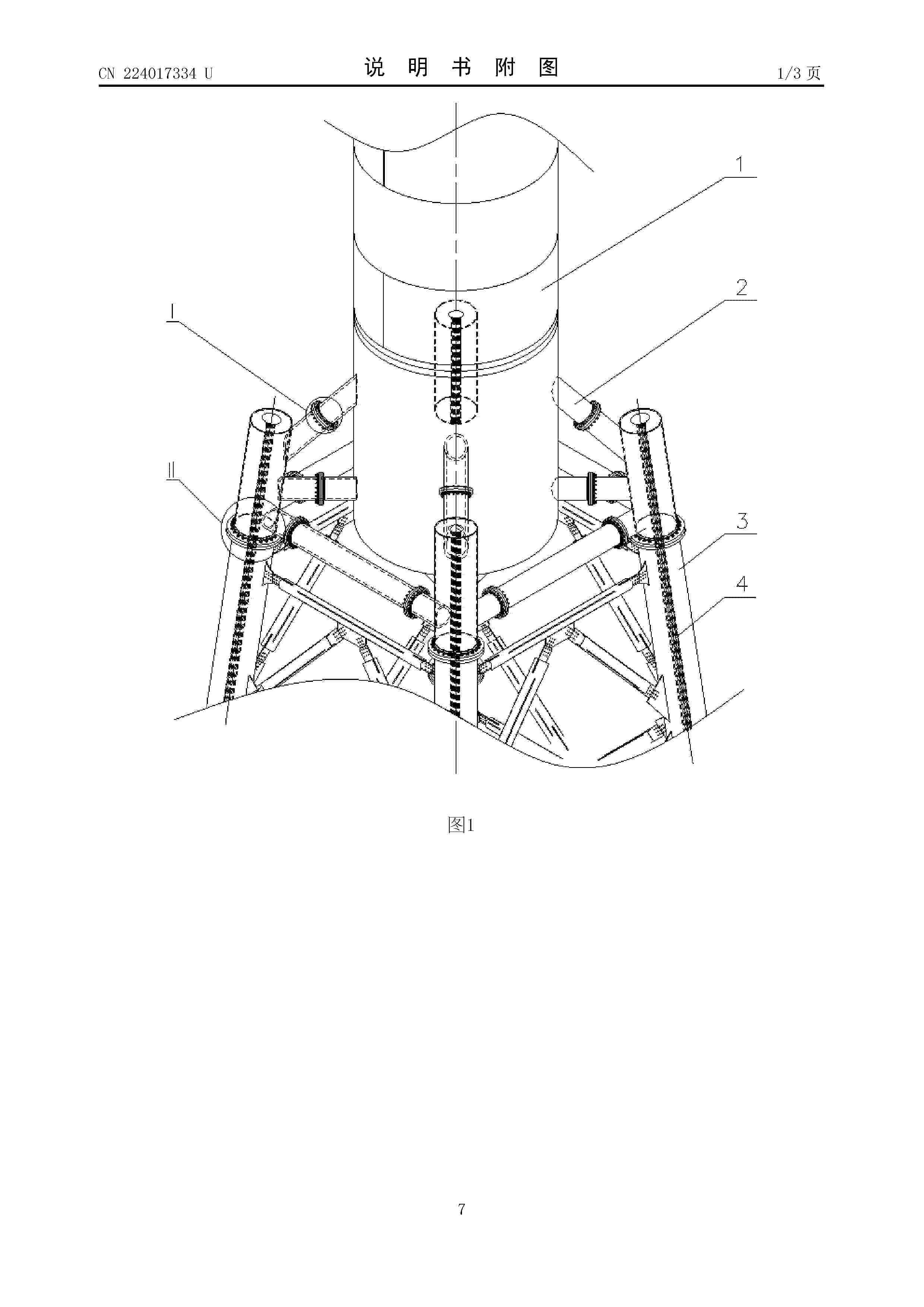
本发明涉及风力发电机组塔架结构技术领域,尤其涉及一种风电塔架过渡转换连接装置及风电塔架。连接装置包括连接筒、连接柱、支撑柱和钢绞线;所述连接筒与塔筒连接,所述连接柱具有多根并位于连接筒的周圈,所述支撑柱的一端与连接柱连接,支撑柱的另一端与连接筒或者连接柱连接;所述连接柱与角柱同轴布置,连接柱的下端与角柱连接,所述角柱和连接柱均具有轴孔,所述钢绞线位于所述轴孔内,钢绞线上端与连接柱连接,钢绞线下端连接基础。通过本发明提高了塔架连接处的结构稳定性和抗疲劳性,延长使用寿命。
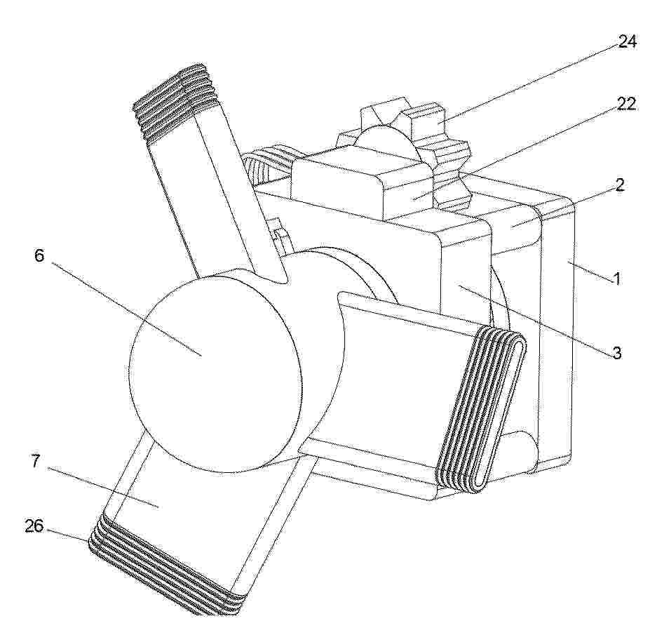
Resumen de: CN224017328U
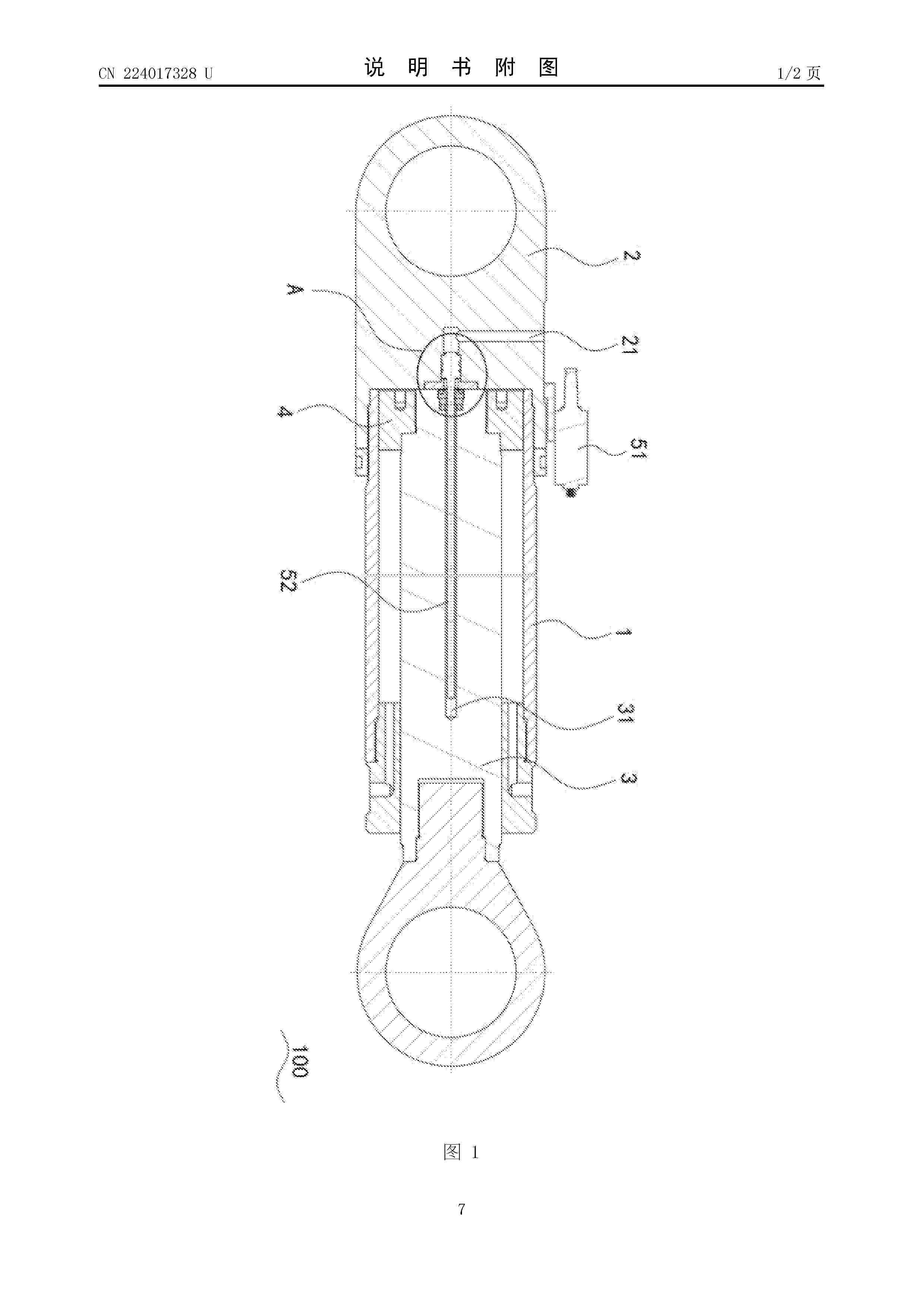
本实用新型涉及风力发电领域,尤其涉及一种带检测功能的风电变桨调向装置及具有其的风力发电装置。其中,带检测功能的风电变桨调向装置包括缸筒和连接在缸筒一端的缸筒盖,缸筒内设置有活塞杆,活塞杆在缸筒内的一端安装有活塞:还包括分体式传感器和磁性组件,磁性组件设置在活塞杆上,分体式传感器包括电子仓和测量杆,电子仓和测量杆通过导线连接,电子仓拆卸固定在缸筒盖上,活塞杆内设置有轴向延伸盲孔,测量杆部分穿设在盲孔内。该带检测功能的风电变桨调向装置同时兼备了结构紧凑与外置维护方便的优点,不光增加了风机上设备的维护效率,更是降低了高空、狭窄通道内拆卸装置带来的安全问题。
Resumen de: CN224017335U
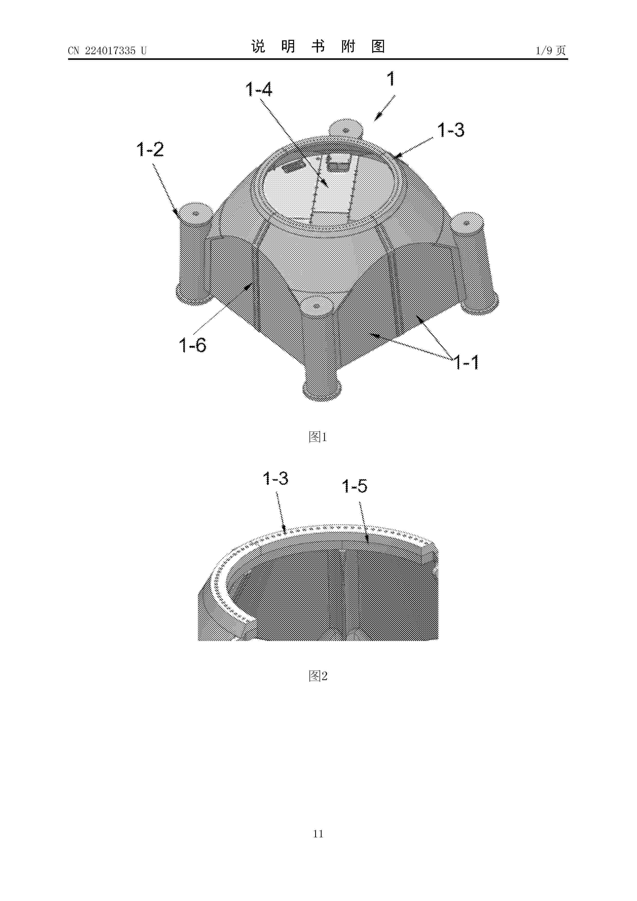
本实用新型公开了一种用于风电机组塔架的过渡转接段结构及风电机组塔架,解决了传统塔架的过渡转接段结构稳定性差的问题,技术方案包括:多个分瓣结构,并拼接组成上圆下方结构,每个所述分瓣结构的侧部设置有角柱座;所述过渡转接段的上端面上设置有钢塔连接法兰,用于连接所述钢塔段;所述钢塔连接法兰的下部还设置有补强法兰,所述补强法兰由多个分瓣法兰组成,每个所述分瓣法兰与一个分瓣结构固定连接为一体结构;所述过渡转接段的相邻分瓣结构拼接缝的内侧和外侧均设置有一根板条,每根板条上设置有双排连接孔,所述过渡转接段的相邻分瓣结构靠近拼接缝处均设置有一排连接孔,并利用双排高强紧固件及两根板条将相邻分瓣结构拼接缝夹紧固定连接。
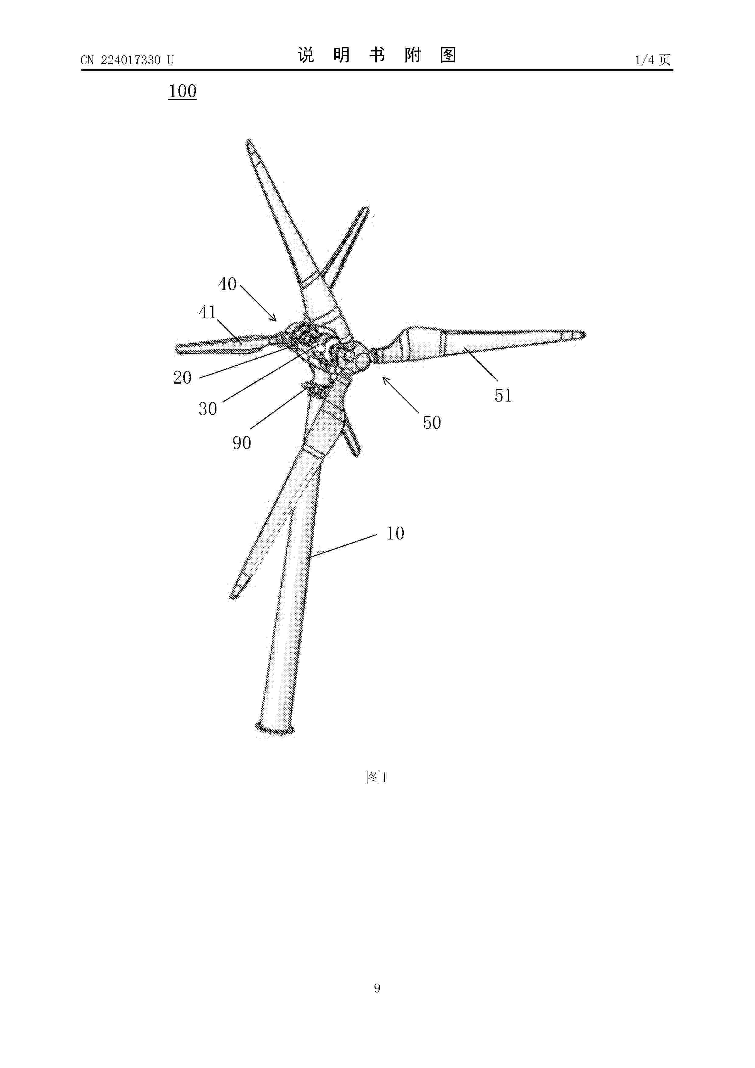
Resumen de: CN224017330U
本申请提供了一种双机头同轴风力发电机,包括:塔架;机舱,设置于塔架的顶部;发电机,设置于机舱,发电机包括电机主轴,电机主轴包括沿长度方向的第一连接端和第二连接端;第一风轮,包括多个第一叶片;第二风轮,包括多个第二叶片,第二叶片比第一叶片大;其中,第一风轮通过第一离合器与电机主轴的第一连接端连接,第二风轮通过第二离合器与电机主轴的所述二连接端连接,第一离合器和第二离合器配置为使第一风轮和/或第二风轮与所述电机主轴连接。本申请能够提升风能利用率,从而提升发电效率。
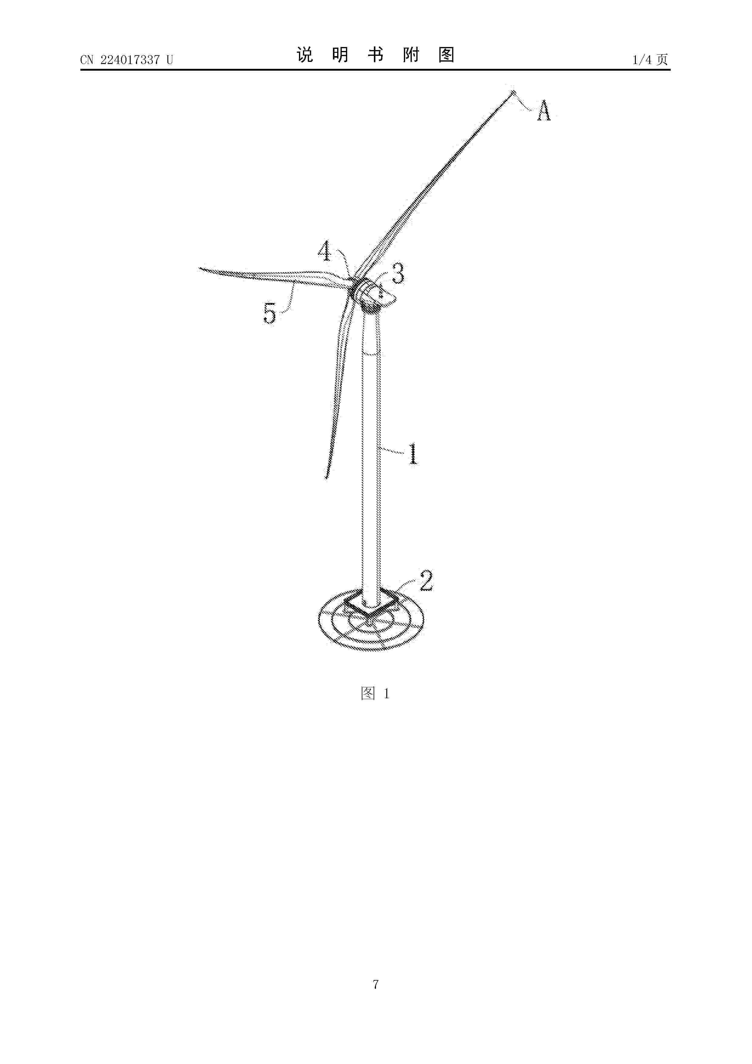
Resumen de: CN224017337U
本申请公开了一种风力发电机散热型防雷装置,属于风力发电机技术领域。主要包括接闪器,接闪器分别通过叶片中排布的第一导线与引雷组件固定连接,引雷组件包括导电环、定环、插板、钢刷和引雷导线,第一导线分别与导电环的侧壁固定连接,定环的一侧分别与插板的一端固定连接,插板的另一端位于导电环的内侧,钢刷固定安装在插板的另一端上,钢刷在滑槽中滑动连接,定环的另一侧分别固定连接有多个引雷导线,引雷组件采用铜、铝等具有高导热系数的金属材料,利用其良好的导热性能,在传导雷电电流过程中能迅速将电流热效应产生的热量吸收并传导至周围空气,通过空气对流实现散热。
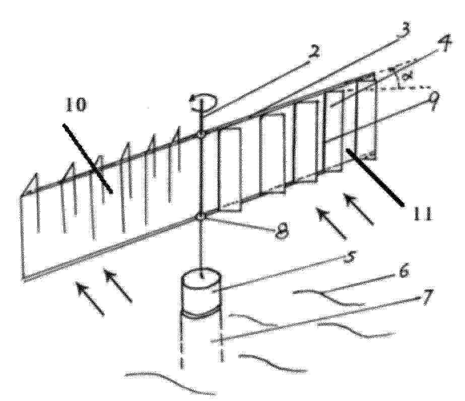
Resumen de: CN121701388A
本发明公开了一种船帆百叶式发电机组及发电方法,包括海底支座柱,海底支座柱上固定连接有发电机,发电机上连接有发电机轴,发电机轴上固定安装有方框;方框被发电机轴分割为第一框和第二框,第一框和第二框相互平行的内侧壁面上均开设有若干组对称的轴孔,每组轴孔内均转动连接有百叶片轴,百叶片轴上可转动连接有百叶片,百叶片轴的轴线与发电机轴的轴线相垂直。整体结构无复杂电控元件,百叶片的旋转仅依赖机械联动与风场作用,相比传统风机的电控调节系统,降低故障发生率且百叶片可单独拆卸更换,无需整体停机检修,减少维护时间。
Resumen de: CN121701391A
本发明公开了一种风电机组有功功率控制装置,属于功率控制装置技术领域。包括支撑板,所述支撑板的左侧对称固定连接有支撑柱,所述支撑柱的左端共同固定连接有一个承重板,所述承重板与所述支撑板的内部均开设有圆槽,所述圆槽的内部转动连接有转柱,所述转柱的左侧固定连接有风机头,所述风机头的外侧壁对称固定连接有扇叶;该装置通过构建精准的转速管控机制,大幅提升了风电机组运行过程中的安全性。在机组运行时,核心控制单元能够实时追踪风机头的转动状态,一旦发现转速接近或超过安全运行的临界值,会迅速启动调控程序。其通过信号传递触发动力部件调整输出强度。
Resumen de: CN121701386A
一种风电叶片的贯索缠绕式扰流元件安装装置,包括绳索和多个定位块,两组定位块分别位于风电叶片沿宽度方向的两侧,定位块通过叶片定位槽卡设安装在风电叶片的侧棱上,定位块包括长条定位块和/或单式定位块,长条定位块远离定位槽的一侧间隔连接有多个绳索限位块,单式定位块远离定位槽的一侧连接有一个绳索限位块,绳索限位块的一侧开设有绳索限位槽,绳索以螺旋形式缠绕在风电叶片上,并依次穿设在风电叶片两侧的绳索限位槽内。本发明通过"缠绕+定距"的双约束机制协同作用,实现叶片与扰流元件之间的稳定连接与精准定位,从而保证扰流元件的间距、位置精度满足气流调控需求。
Resumen de: CN121701417A
本公开提供一种风力发电机组的净空保护系统及方法、风力发电机组,所述净空保护系统包括:保护罩,所述保护罩设置在所述风力发电机组的塔架上,位于所述风力发电机组的叶片尖部在扫风过程中所经过的塔架高度处,并且与所述塔架之间形成腔体,所述腔体内的气压在所述保护罩受到所述叶片碰撞时产生变化;压力传感器,所述压力传感器设置在所述腔体中,以用于感测所述腔体内的气压。本公开解决了叶片净空监测设备的成本高、稳定性和普适性差的问题,可以在降低成本的同时提高净空保护的可靠性。
Resumen de: CN121701012A
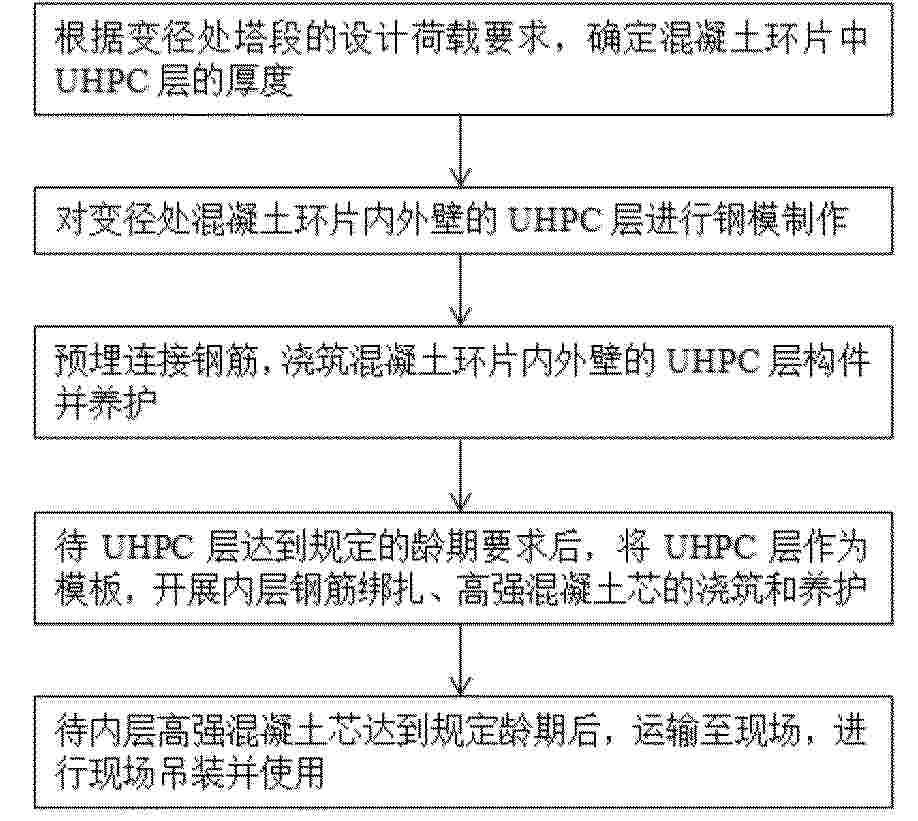
本发明公开了一种风电机组混凝土环片及其设计方法,属于风电场建设施工领域,风电机组混凝土环片的设计方法包括以下步骤:根据变径处塔段的设计荷载要求,确定混凝土环片中UHPC层的厚度;对变径处混凝土环片内外壁的UHPC层进行钢模制作;预埋连接钢筋,浇筑混凝土环片内外壁的UHPC层构件并养护;待UHPC层达到规定的龄期要求后,将UHPC层作为模板,开展内层钢筋绑扎、高强混凝土芯的浇筑和养护;待内层高强混凝土芯达到规定龄期后,运输至现场,进行现场吊装并使用。本发明基于变径塔段的受力特性,提出了UHPC层厚度的计算方式,能够得到满足抗裂控制的最小薄层厚度,从而得到最优的混凝土环片,满足使用需求。
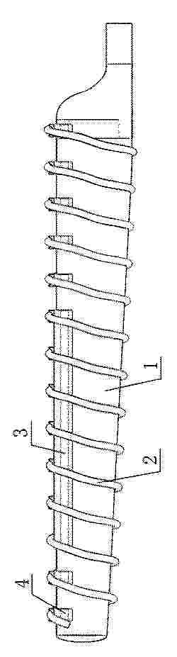
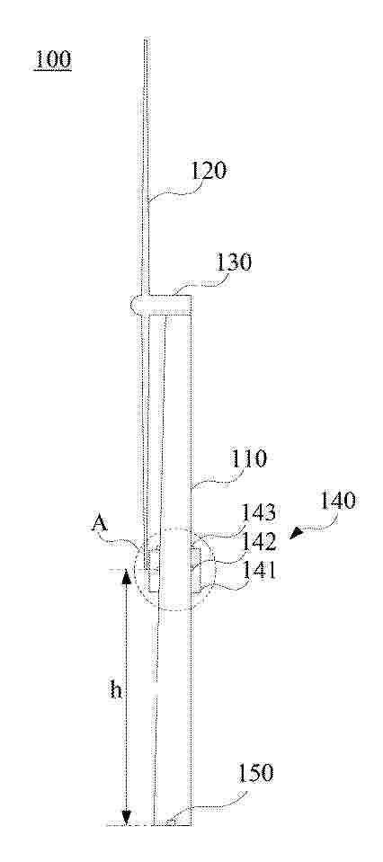
Resumen de: CN224013824U
一种立式风力发电浮标,属于航道航标领域。该浮标在支撑外框架表面设置航道通航标志,内侧安装可转动的风叶转动组件,其与发电机转子配合,发电机定子连接蓄电装置。支撑外框架可为三棱体或柱形结构,顶部和底部设轴承座支撑风叶组件转动,风叶包括三角形叶片和螺旋形叶片两种形式。本浮标将风力发电与浮标功能结合,解决了传统航标单一太阳能供电可靠性低、受光照影响大、供电能力不足等问题,利用风能补充电能,满足设备用电需求;同时不占用甲板平面空间,便于人员作业。
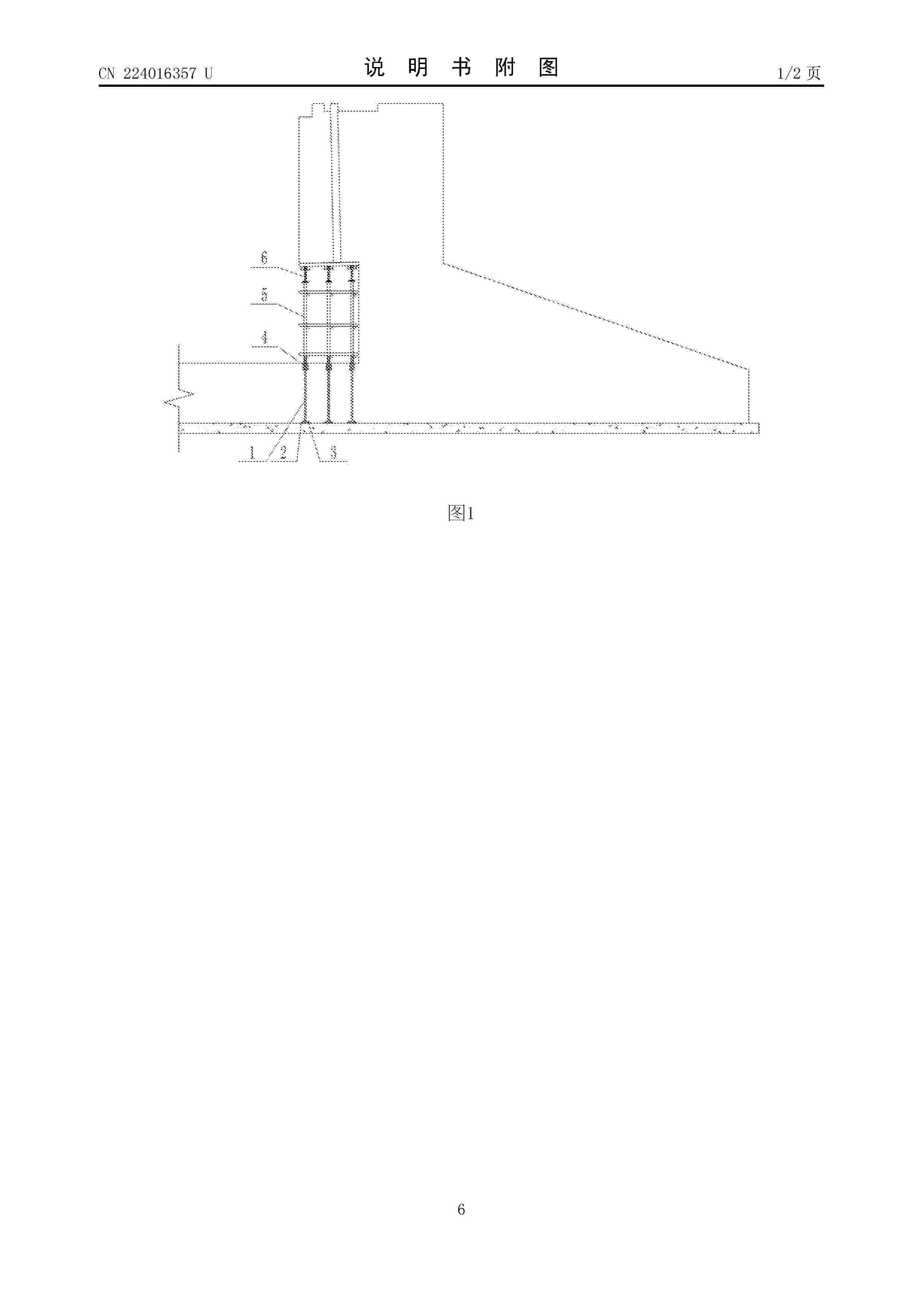
Resumen de: CN224016357U
一种用于风电混塔基础空腔悬挑部分的模板撑脚,包括支撑钢筋I、底部钢板、支撑钢管和可调节托撑,底部钢板设置在风电混塔基础空腔悬挑部分下方的混凝土中,支撑钢筋I的下方垂直焊接一根与底部钢板焊接的钢筋,钢筋的底部与底部钢板焊接,支撑钢筋I的上部四周焊接四根支撑钢筋II,支撑钢管套接在支撑钢筋I的顶部,且支撑钢筋II与支撑钢管的管壁接触。本实用新型的支撑钢管可以回收再利用,避免了传统支模方法中钢管无法回收的情况,从而减少了钢管浪费,降低施工成本,基础钢筋加工的废料可以作为模板撑脚的原材料,合理利用废料,底部钢板的设计相较于钢管支撑延长了渗水路径,有效防止混凝土渗水,增强了结构的防水效果。
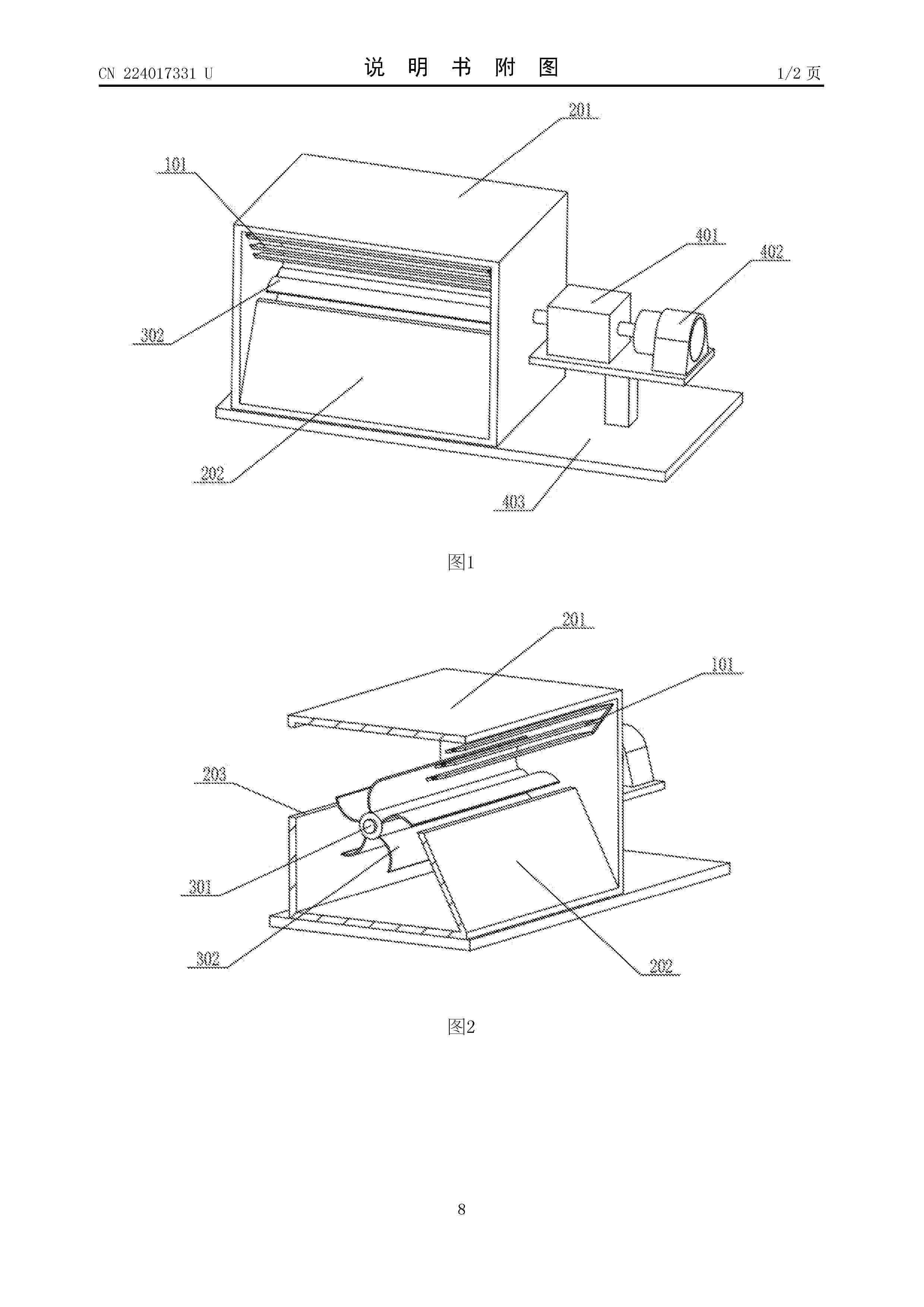
Nº publicación: CN224017331U 20/03/2026
Solicitante:
银川科技学院
Resumen de: CN224017331U
本实用新型属于风力发电技术领域,具体涉及一种可调风速的风力发电机;包括:风力组件,用于被风吹动旋转;外壳组件,所述发电组件转动连接于所述外壳组件中,所述外壳组件包括导向部,所述导向部用于调整风作用在所述风力组件上的面积;发电组件,所述发电组件设置于所述外壳组件外部且与所述发电组件连接,由所述发电组件驱动产生电能;使流过风力组件的风量趋于稳定,实现稳定的发电;降低风速的复杂变化对风力组件的影响,杜绝在风力发电的过程中出现间歇性导致风电并网困难,并且能够使风力组件的转速保持稳定稳定,提高能量转换效率。
 BOPI
BOPI
 Sede Electrónica