Si deseas distinguir tus productos, servicios o ambos de los de otra empresa, es posible que necesites una marca o nombre comercial. Descubre qué son, en qué consiste su procedimiento de registro y qué implica.

Información sobre los plazos de presentación de solicitudes de transformación de marcas de la Unión Europea en marca nacional española. Más información


Si tienes un nuevo dispositivo, producto o procedimiento que resuelva un problema técnico o tenga una ventaja práctica, existen distintas formas de protegerlo en España y en otros países. Descubre cómo hacerlo.

¿Tu innovación reside en la estética, la ornamentación o la apariencia de tu producto? Protégela mediante un diseño industrial. Descubre qué derechos confiere el registro y cómo realizar la tramitación.

Las indicaciones geográficas protegen el nombre de un producto originario de una zona geográfica, a la cual le debe una determinada calidad, reputación u otra característica. Descubre qué son, en qué consiste su procedimiento de registro y qué beneficios conceden.

Las patentes publicadas en todo el mundo son una valiosa fuente de información científica, técnica y comercial.

Si eres emprendedor/a o una empresa y quieres potenciar y mejorar la rentabilidad de tu negocio protegiendo de forma adecuada los activos intangibles de tu organización, en este espacio encontrarás lo necesario.


 470
resultados
470
resultados
 Última actualización
28/07/2026 [07:09:00]
Última actualización
28/07/2026 [07:09:00]


Resumen de: CN122453316A
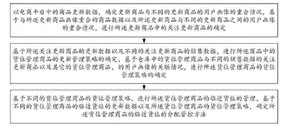
本发明提供一种考虑商品订单数据的动态货位智能分配方法与系统,属于货位管理技术领域,具体包括:基于仓库中的货位管理商品与不同的销售数据的关注更新商品以及其它的货位管理商品,的用户画像的关联情况,进行货位管理商品的货位管理策略的确定,基于不同的货位管理商品的货位管理策略,进行货位管理商品的临近货位的管理,基于不同的货位管理商品的临近货位的更新数据以及货位管理商品的货位管理策略,确定货位管理商品的临近货位的分配管控方法,提升了货位更新处理的可靠程度。

Resumen de: CN122453074A
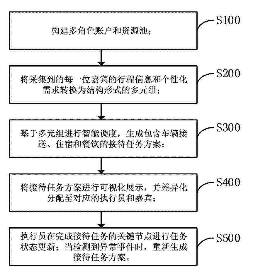
本发明提供了一种面向多角色会展场景的智能接待调度与信息协同方法及系统,旨在解决现有技术会展接待中信息割裂、调度人工依赖度高,以及多角色协同困难的问题。本发明包括构建多角色账户和资源池;将采集到的嘉宾行程信息和个性化需求转换为结构形式的多元组;基于多元组进行智能调度,生成包含车辆接送、住宿和餐饮的接待任务方案;将接待任务方案进行可视化展示,并差异化分配至对应的执行员和嘉宾,支持任务状态更新和重调度机制。本发明不仅仅是单一调度,而是联动接送、入住、餐饮三个业务板块的接待安排和状态变更,且实现多角色的信息同步。
Resumen de: CN122453030A
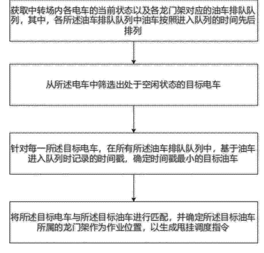
本申请实施例涉及物流车辆甩挂调度方法,包括:获取中转场内各电车的当前状态以及各龙门架对应的油车排队队列,各所述油车排队队列中油车按照进入队列的时间先后排列;从所述电车中筛选出处于空闲状态的目标电车;针对每一所述目标电车,在所有所述油车排队队列中,基于油车进入队列时记录的时间戳,确定时间戳最小的目标油车;将所述目标电车与所述目标油车进行匹配,并确定所述目标油车所属的龙门架作为作业位置,以生成甩挂调度指令。将原有局部队列分配转变为全局统一选择,从而避免不同队列之间等待时间不均的问题;由电车主动触发匹配,使调度过程能够在电车空闲时即时执行,减少电车空闲时间,实现油车、电车与龙门架之间的协同调度。
Resumen de: CN122453111A
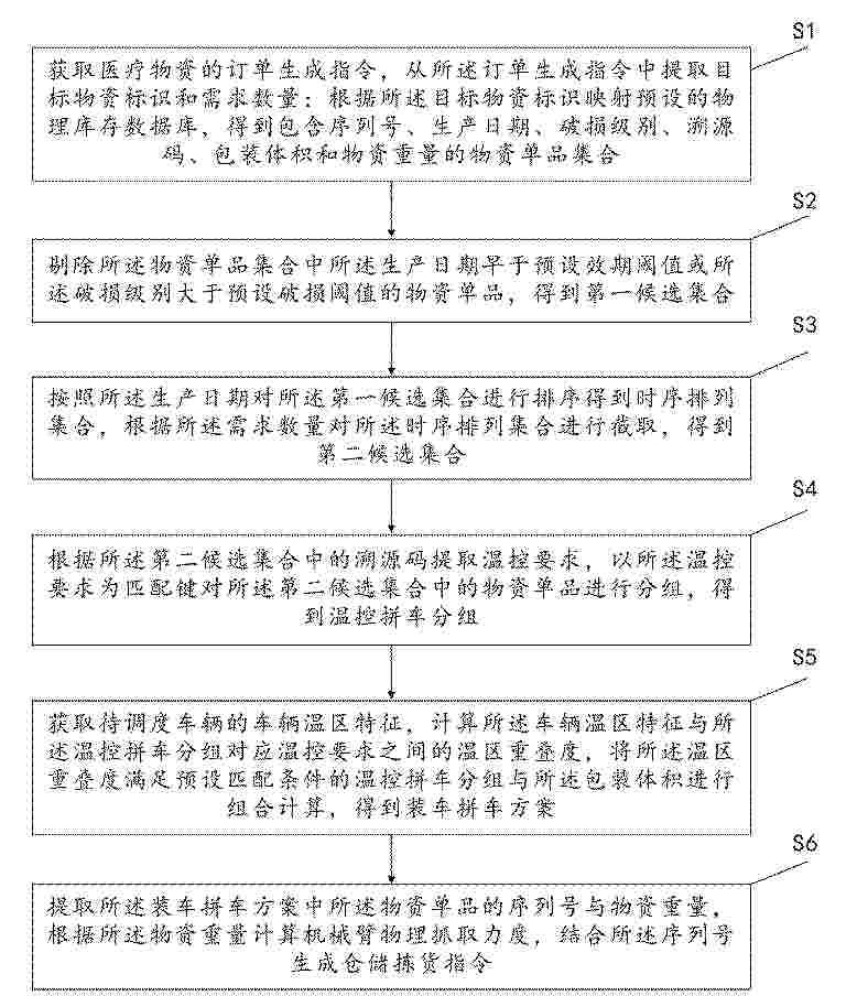
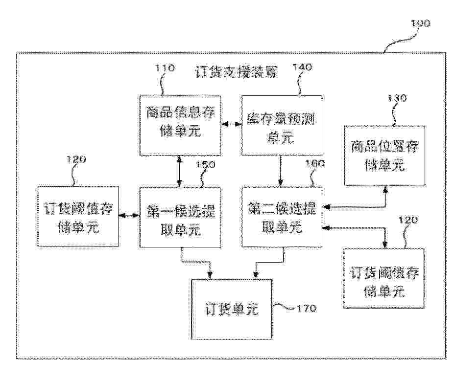
本发明涉及仓储物流及数据处理技术领域,公开了一种医疗物资供应链订单调度方法及系统,所述方法包括获取医疗物资的订单生成指令并提取目标物资标识和需求数量;根据目标物资标识映射预设的物理库存数据库,得到物资单品集合;对物资单品集合进行剔除得到第一候选集合,再排序截取得到第二候选集合;根据第二候选集合中的溯源码提取温控要求并进行分组,得到温控拼车分组;计算待调度车辆的车辆温区特征与温控拼车分组对应温控要求之间的温区重叠度,结合包装体积进行组合计算,得到装车拼车方案;根据装车拼车方案中所述物资单品的物资重量计算机械臂物理抓取力度,生成仓储拣货指令。本方法能够实现全链路闭环订单调度。
Resumen de: CN122453148A
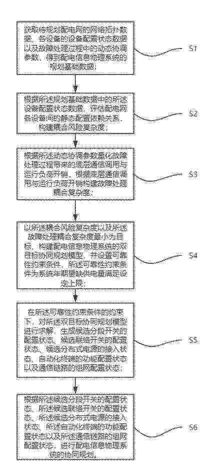
本发明公开了一种配电信息物理系统协同规划方法、装置、终端设备及计算机可读存储介质,属于配电网规划技术领域。方法包括:获取网络拓扑数据、设备配置状态数据及动态协调参数得到规划基础数据;根据所述设备配置状态数据评估静态配置依赖关系,构建耦合风险复杂度;根据所述动态协调参数量化底层通信调用与运行负荷开销,构建故障处理耦合复杂度;以上述的两项复杂度最小为优化目标,并以系统年期望缺供电量满足上限为约束条件,构建并求解双目标协同规划模型,生成各设备的配置状态组合以进行协同规划。本发明解决了现有配电网规划因忽略底层通信与物理运行开销,导致自动化设备过度配置而引发系统超载及通信拥堵的问题。
Resumen de: CN122453423A
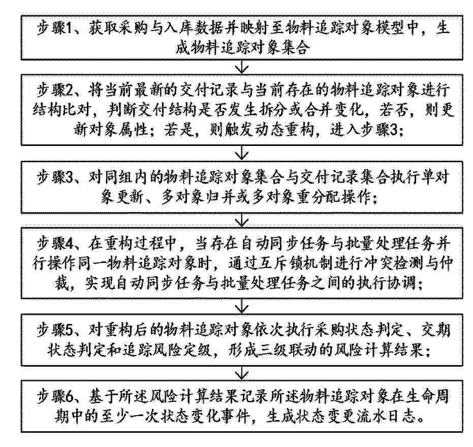
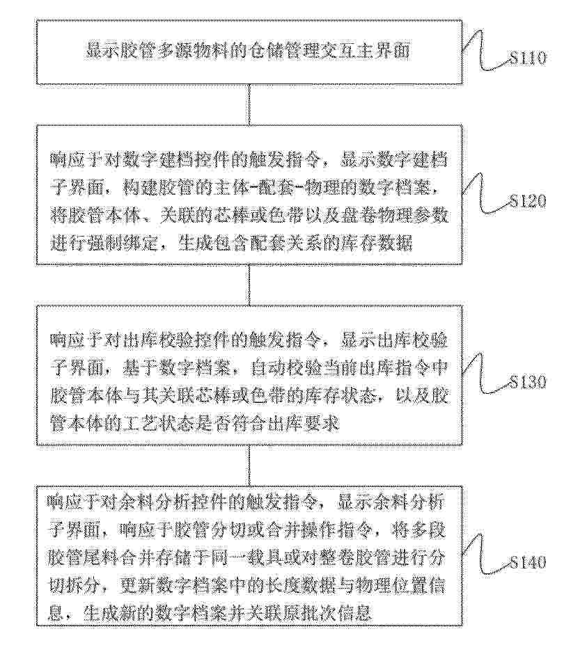
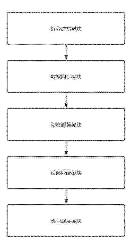
本发明公开了一种基于多源异构数据的物料追踪控制方法,包括:获取采购与入库数据并映射至物料追踪对象模型中生成物料追踪对象集合;将当前最新的交付记录与当前存在的物料追踪对象进行结构比对,判断交付结构是否发生拆分或合并变化;对同组内的物料追踪对象集合与交付记录集合执行单对象更新、多对象归并或多对象重分配操作;当存在自动同步任务与批量处理任务并行操作时,通过互斥锁机制进行冲突检测与仲裁;对重构后的物料追踪对象依次执行采购状态判定、交期状态判定和追踪风险定级,形成三级联动的风险计算结果;记录物料追踪对象的状态变化,生成状态变更流水日志。本发明实现对物料进行持续追踪、动态重构、风险识别和一致性控制。
Resumen de: CN122453011A
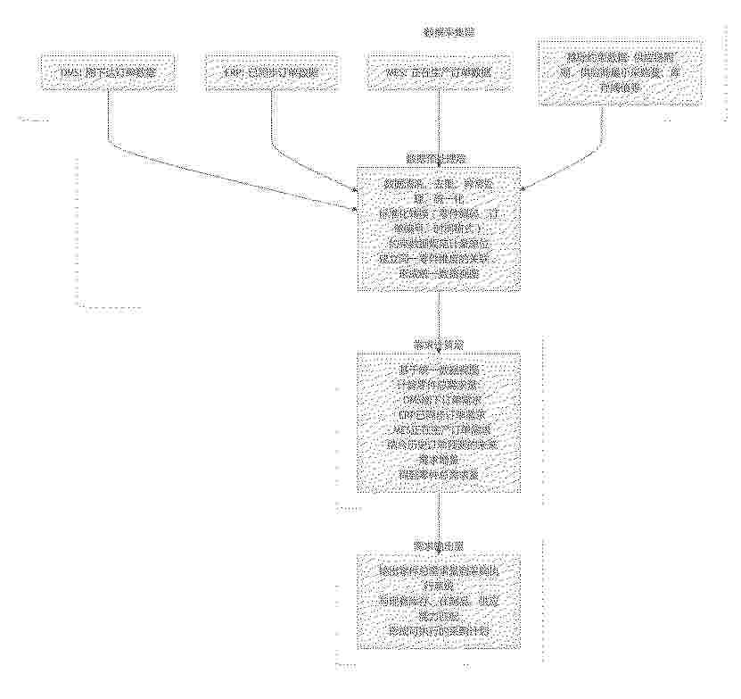
本发明公开了一种多系统订单数据联动的零件采购需求实时生成方法,涉及数据处理大数据分析、多系统信息整合与采购管理领域。该方法包括:数据采集层实时从OMS、ERP、MES及PML等系统采集多类型订单数据与基础约束数据;数据预处理层对多源数据进行清洗、标准化及关联,构建以零件维度的统一视图;需求计算层统一视图及约束条件,实时计算包含已下达订单、在产订单及历史预测的总需求量;需求输出层将总需求量与库存、在制品及供应能力进行匹配,生成可执行的采购计划。本发明解决了现有技术中存在的数据孤岛、约束单一及响应滞后的问题,实现了采购需求与生产状态、供应链能力及库存约束的动态精准匹配。
Resumen de: CN122452991A
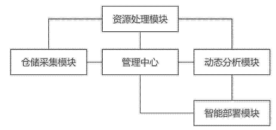
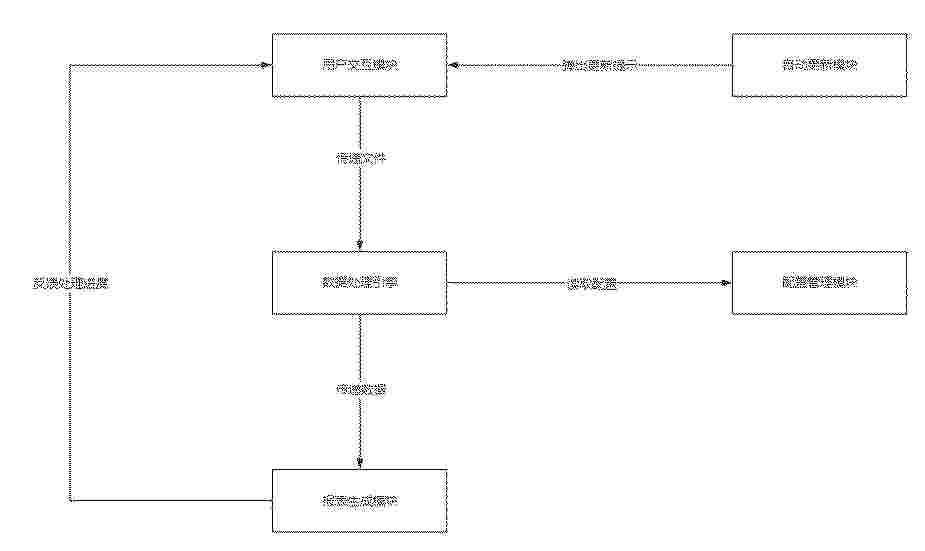
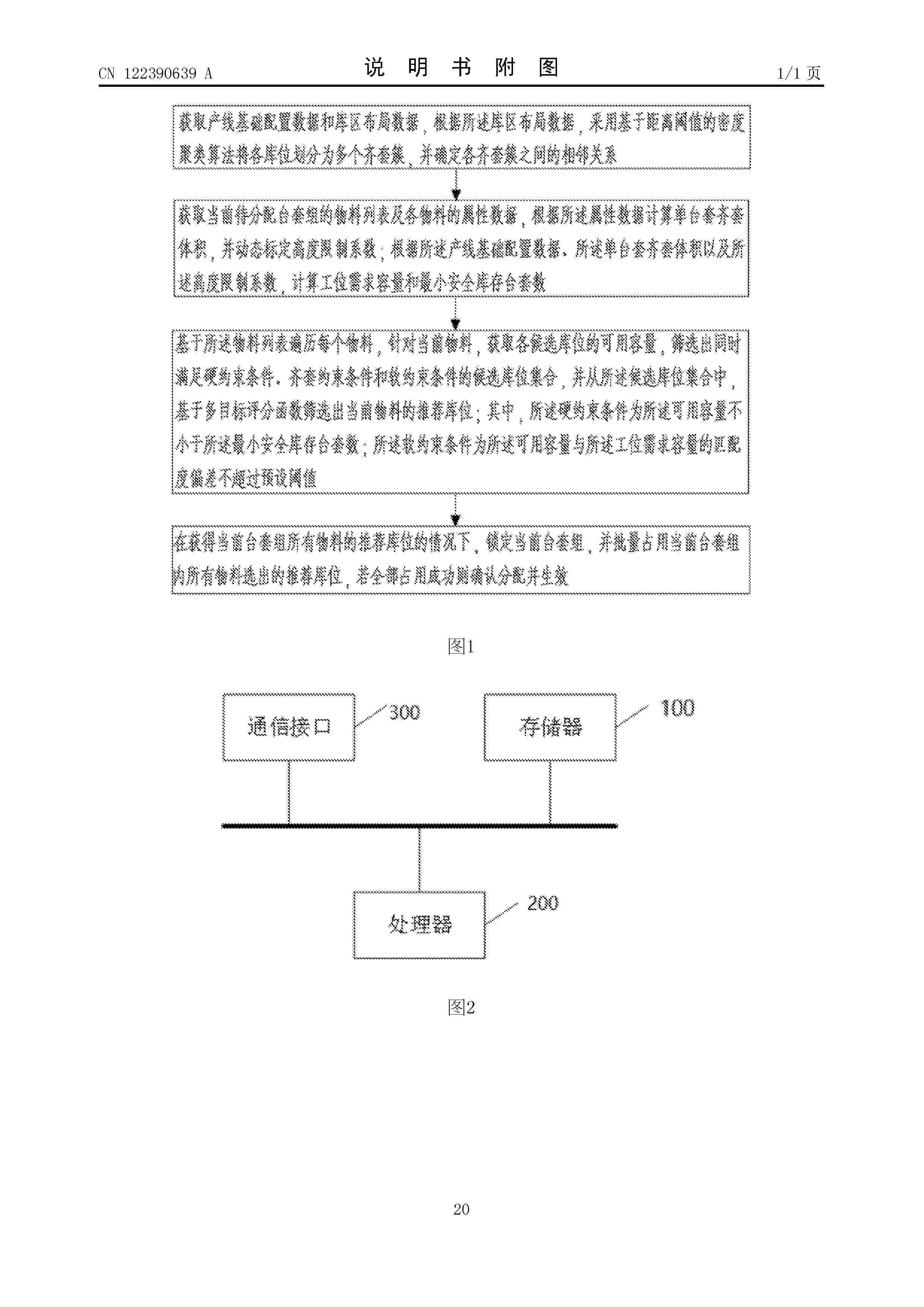
本发明公开了基于人工智能的供应链仓储资源动态分配系统及方法,涉及仓储管理技术领域,包括管理中心,所述管理中心连接有仓储采集模块、资源处理模块、动态分析模块以及智能部署模块;为供应链仓储构建虚拟视觉空间,采集仓储资源数据和订单任务数据;根据订单任务数据对仓储资源数据进行分类构建,获得资源类别存储库;根据资源类别存储库对目标用户的可用仓储进行容量可视化,获得备选资源类别容量图;通过虚拟视觉空间对备选资源类别容量图进行需求约束并排序,获得仓储资源容量序列,根据仓储资源容量序列在虚拟视觉空间对目标用户进行方案模拟优化,获得最佳动态分配方案;大幅提升仓储作业效率与空间利用率。
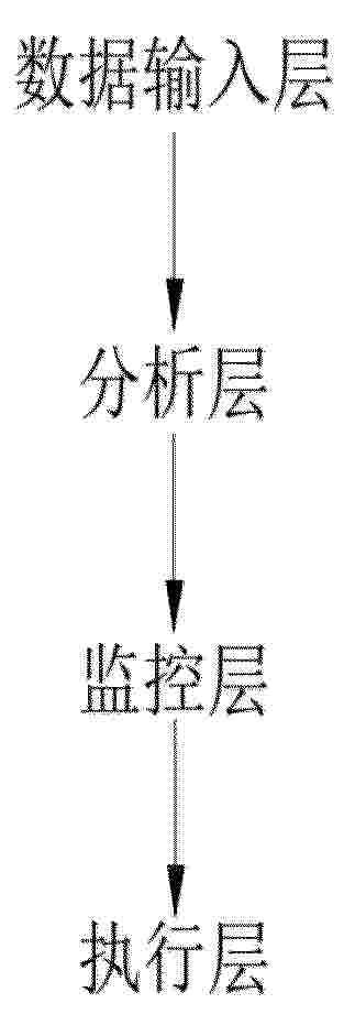
Resumen de: CN122453305A
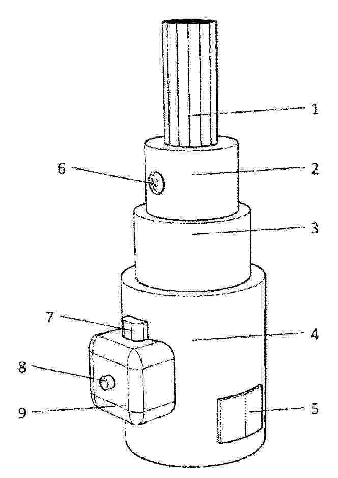
本发明涉及监控平台技术领域,更具体的说是一种互联网安全监控平台,包括:数据输入层,用于接收订单信息;分析层,用于分析订单数据;监控层,用于订单实时监控;执行层,用于用户对订单进行操作;所述执行层包括执行模块,执行模块包括底盘,底盘上侧固接有支撑杆,支撑杆上固接有顶板,顶板上加工有环槽,环槽内滑动连接有多个滑杆,每个滑杆上端均固接有压板,每个压板上侧均固接有面板,每个滑杆外侧均滑动连接有滑板,每个对应的滑板与压板之间均固接有弹簧,每个滑杆底部均滑动连接有套筒,每个套筒内部均胶合有电磁铁,每个套筒底部均固接有极板,底盘上加工有滑槽,滑槽内胶合有电极Ⅰ和电极Ⅱ,其有益效果为实现用户订单的及时纠错。
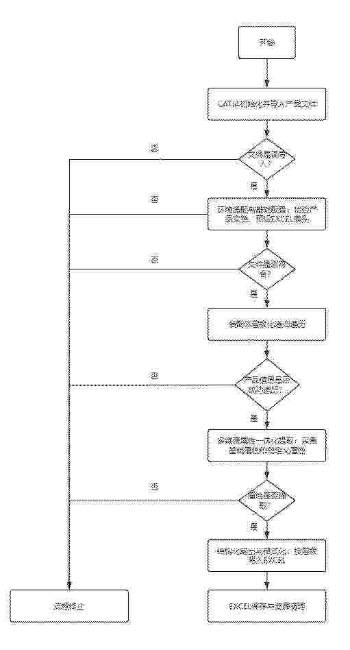
Resumen de: CN122452318A
本发明属于计算机辅助设计软件数据处理技术领域,本发明公开了一种基于CATIA二次开发的层级化属性提取方法及系统。该方法包括:通过深度优先递归算法遍历CATIA装配树;在遍历过程中记录每个零部件的层级深度;根据零部件类型是装配体或零件,采用差异化策略提取其属性信息;最后将层级深度、类型及属性信息按结构化格式输出,生成层级化物料清单。本发明通过递归遍历完整保留了产品的装配层级结构,通过差异化提取确保了各类属性获取的准确性,实现了从CATIA设计模型到结构化BOM的全自动、高保真转换,克服了传统方案丢失层级、依赖第三方插件、效率低下的问题,具有兼容性好、成本低、灵活可扩展的优点。
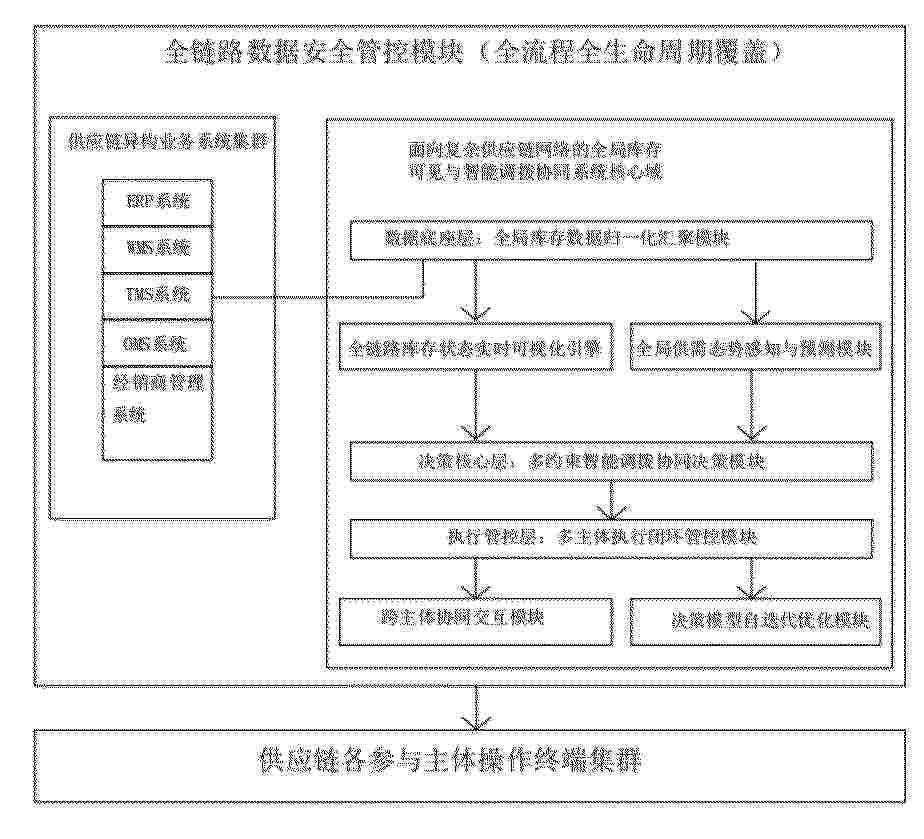
Resumen de: CN122452997A
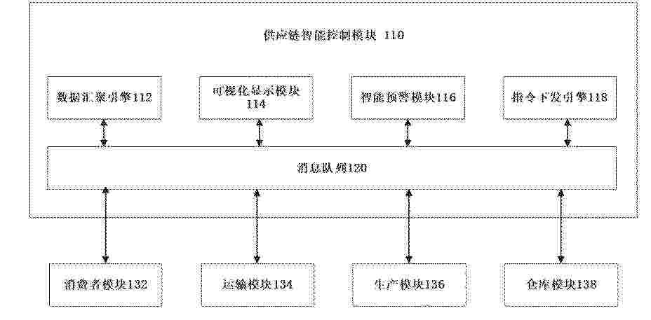
本发明提供了一种面向复杂供应链网络的全局库存可见与智能调拨协同系统,属于供应链库存管理与智能协同技术领域。本系统解决传统供应链模式中信息孤岛突出、库存状态不透明、调拨决策局部化、执行闭环缺失、场景适配性不足的问题。系统搭建从数据汇聚、状态可视化、供需态势感知、智能调拨决策、执行闭环管控到模型自迭代优化的全链路闭环架构,设置对应功能模块实现全流程协同管控。本发明可实现复杂供应链全链路库存的端到端透明可见与全局调拨协同优化,提升供应链运行效率,降低全链路运营成本,适配不同结构的复杂供应链网络运行需求。
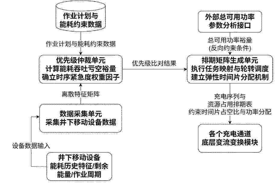
Resumen de: CN122453095A
本发明属于生产管理信息化与资源运筹调度优化技术领域,涉及一种井下充电硐室资源动态调度管理系统及方法,包括:数据采集单元采集井下移动设备数据并输出离散特征矩阵;优先级仲裁单元根据作业计划与能耗约束计算能耗吞吐亏空裕量,并结合交接班缓冲时间确立时序紧急度权重因子以输出优先级比对结果;排期矩阵生成单元将总可用功率裕量作为反向约束条件带入离散特征矩阵的路径规划流程以建立弹性时间片分配机制,根据优先级比对结果约束各充电通道的时序时间片占空比与功率分配额度,输出充电序列与资源占用排期表,本发明通过优化调度管理决策算法重构弹性时间片分配机制,实现生产资源与设备排班的精细化协同配置。
Resumen de: CN122453306A
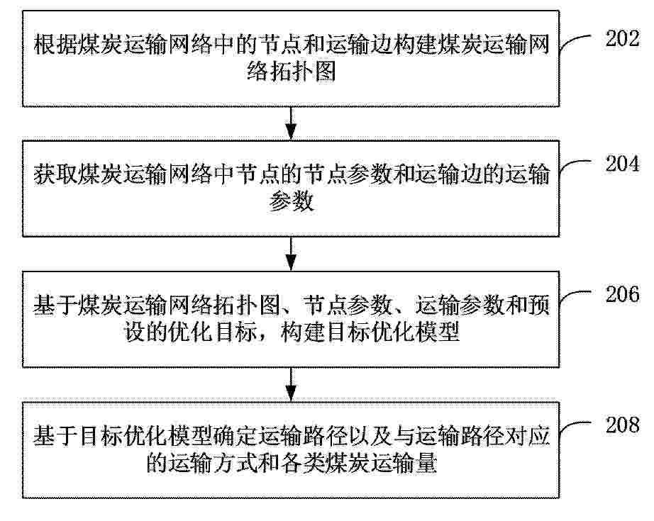
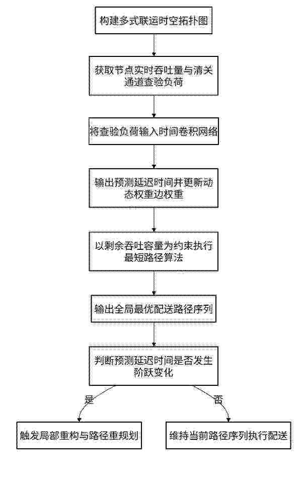
本申请涉及一种多式联运运输规划方法、装置、计算机设备、介质和计算机程序产品。方法包括:根据煤炭运输网络中的节点和运输边构建煤炭运输网络拓扑图;节点和运输边的数量均为多个,运输边为节点之间的运输路径;获取煤炭运输网络中节点的节点参数和运输边的运输参数;基于煤炭运输网络拓扑图、节点参数、运输参数和预设的优化目标,构建目标优化模型;基于目标优化模型确定运输路径以及与运输路径对应的运输方式和各类煤炭运输量。采用本方法能够在符合实际运输情况的前提下,规划能够满足用户实际需求的运输路径、各个运输路径对应的运输方式和不同种类煤炭的运输量,从而能够适应用户的实际需求、提升运输整体效能。
Resumen de: CN122453289A
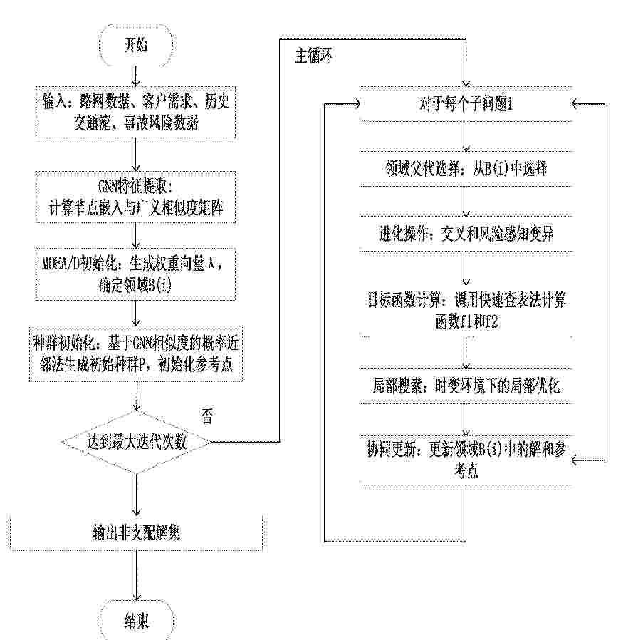
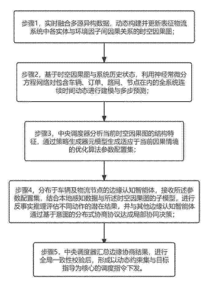
本发明提供了一种基于时空特征增强与图神经网络引导的多目标路径协同优化方法,包括:步骤1,构建支撑路径优化的基础数据体系;步骤2,生成能够引导路径搜索的节点嵌入向量;步骤3,重构配送任务在特征空间中的关联性,通过启发式引导生成高质量的初始解集;步骤4,通过改进的遗传算子实现对配送方案的精细化迭代;步骤5,建立基于时间轴离散化预处理与状态递归的快速查表机制。本方法有效提升了路径规划方案的现实适配性与算法寻优精度,实现了配送效率与行车安全的协同优化,大幅降低了动态场景下的计算复杂度,可生成兼顾多目标需求的帕累托最优解,满足复杂城市配送场景的实时调度与决策需求,具备良好的工程应用价值。
Resumen de: CN122453307A
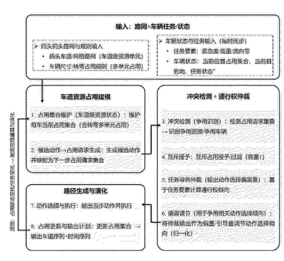
本发明涉及一种任务导向下集装箱码头内智能转运车车道级路线规划方法及系统,该方法包括:S1、获取由集装箱码头车道路网进行建模得到的有向网格图,并获取每个时间步下每辆智能转运车的任务状态信息;S2、在每个时间步内,为每辆智能转运车生成候选动作集合,并将其映射为下一时间步占用请求集合;S3、汇集所有下一时间步占用请求集合,进行冲突检测和优先级裁决,得到每辆智能转运车的占用授予结果,并按照占用授予结果进行执行;S4、在占用授予结果执行的基础上,返回步骤S2进行时间步推进与循环,直至每辆智能转运车完成任务,得到实时演化的车道级轨迹。与现有技术相比,本发明具有提高实时响应与冲突控制能力等优点。
Resumen de: CN122451204A
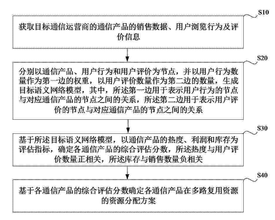
本申请实施例涉及一种推荐资源优化配置方法、设备、存储介质及产品。该方法包括:先获取通信产品的销售数据、用户浏览行为及评价信息,以通信产品、用户行为和评价为节点,再以行为数量作为第一边权重、评价数量作为第二边权重,构建语义网络模型,然后基于该模型,以产品热度、利润和库存为指标,计算各产品的综合评估分数,并据此制定多路复用资源的分配方案。
Resumen de: CN122453293A
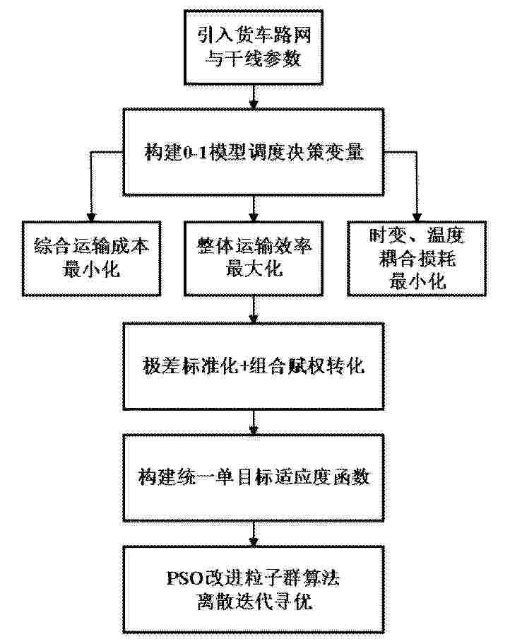
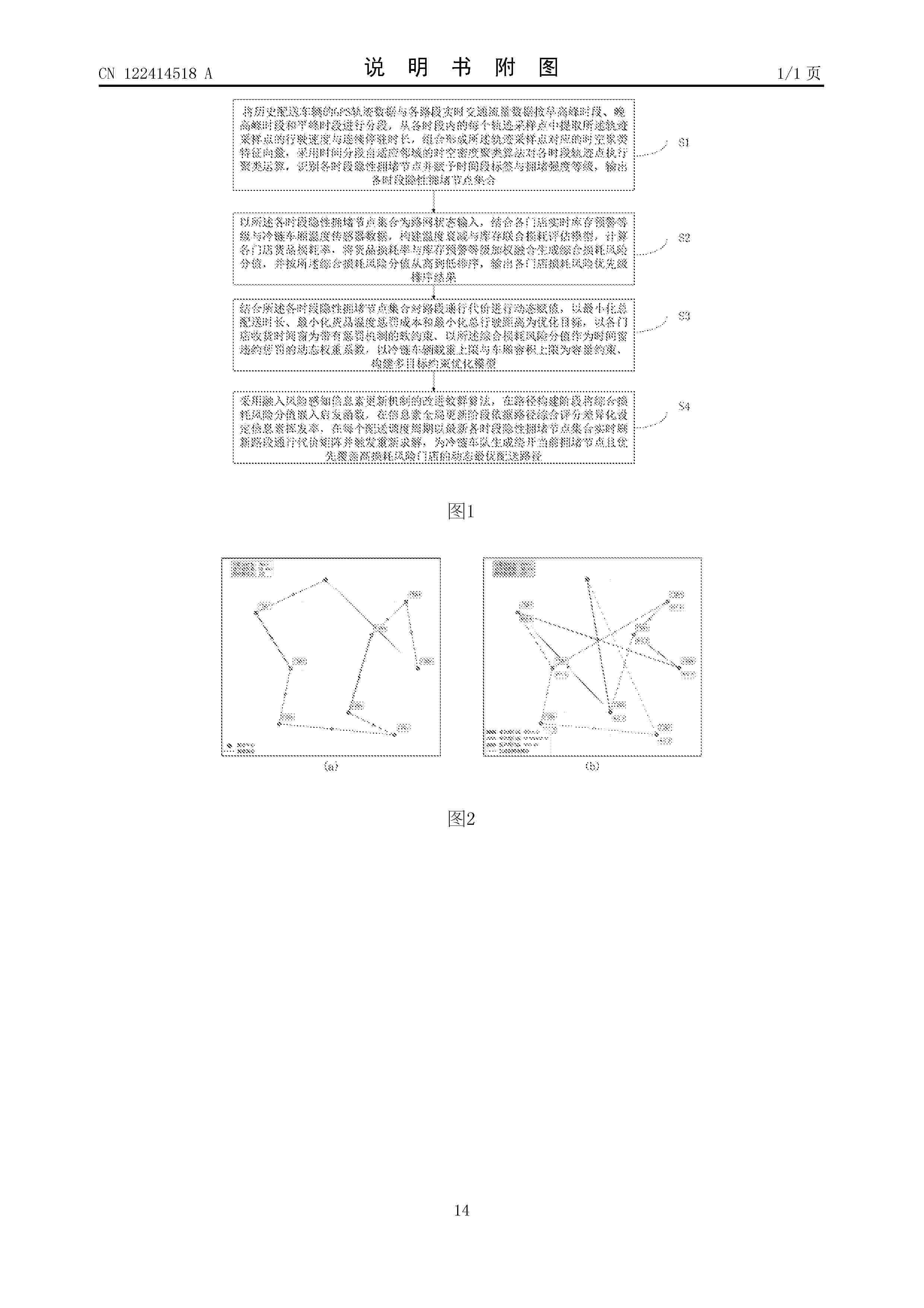
本发明公开了一种面向产品物流的空地协同多目标优化调度方法及系统,包括:定义空地协同中转交接节点,构建0‑1离散调度决策变量并对多源数据进行预处理;从降本、提效、保品质三个维度同步构建多目标联合优化函数;建立涵盖车机载重、无人机低空续航里程、空地衔接时序窗口及任务唯一性在内的全维度硬性约束方程组;利用极差标准化及组合赋权法进行多目标融合,采用面向0‑1离散决策且带惩罚函数的改进粒子群算法进行高效全局寻优迭代,输出最优空地接力协同调度方案。本发明能够同时降低物流运营成本和农产品品质损耗,在满足货车容量、无人机续航及动态载重功耗等异构约束的前提下,为低空配送提供兼顾经济性与时效性的最优调度方案。
Resumen de: CN122453282A
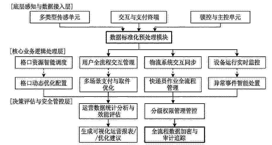
本发明公开了一种快递柜多维度数据采集与高效管理系统,涉及物流末端配送信息管理技术领域,包括多维度数据采集、数据标准化预处理、格口资源智能调度、用户全流程交互管理、物流系统数据交互同步、设备运行状态实时监控、运营数据统计分析、分级权限管理、异常事件智能处置、全流程数据加密存储模块,多维度数据采集模块实时采集快递柜运营全维度数据,其余模块依次完成数据标准化处理、格口智能调度、用户交互管理、物流数据同步、设备运行监控、运营数据分析、分级权限管控、异常事件处置与全流程数据加密存储。本发明可大幅提升快递柜格口资源利用效率与运营管理效率,优化用户寄取件服务体验,缩短设备故障处置周期,降低运维成本。
Resumen de: CN122453486A
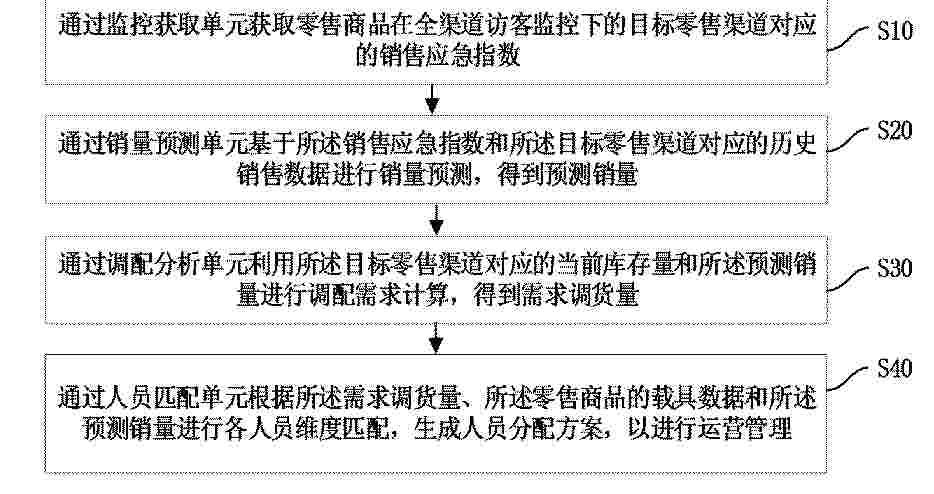
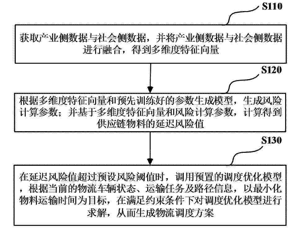
本发明提供一种电子商务全渠道运营管理系统及方法,涉及电商管理技术领域,所述电子商务全渠道运营管理系统,包括:监控获取单元,用于获取零售商品在全渠道访客监控下的目标零售渠道对应的销售应急指数;销量预测单元,用于基于销售应急指数和目标零售渠道对应的历史销售数据进行销量预测,得到预测销量;调配分析单元,用于利用目标零售渠道对应的当前库存量和预测销量进行调配需求计算,得到需求调货量;以及人员匹配单元,用于根据需求调货量、零售商品的载具数据和预测销量进行各人员维度匹配,生成人员分配方案,以进行运营管理。本发明提供的系统及方法,保证了零售商品的运营管理效率。
Resumen de: CN122453120A
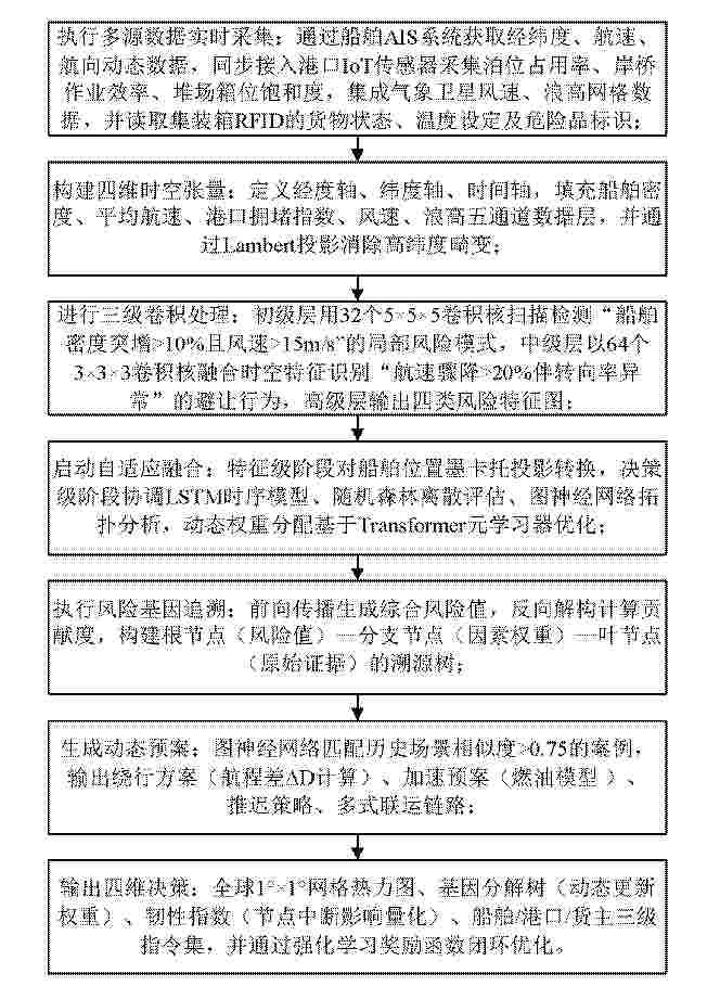
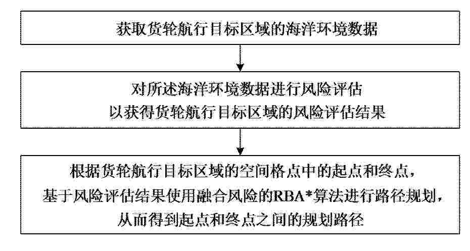
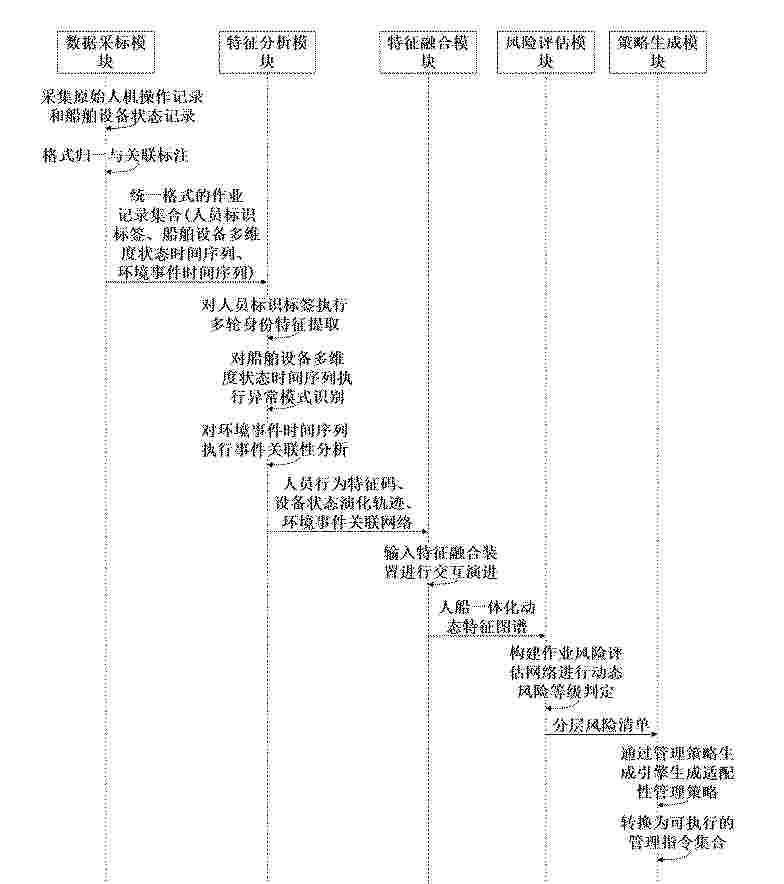
本发明公开了一种基于时空卷积与风险追溯的海运多源数据融合方法,包括以下步骤:利用多尺度三维卷积模型对船舶行驶过程中,实现多类风险特征的识别;引入元学习优化器与注意力机制驱动的自适应融合引擎,对异构数据源在不同场景下赋予动态权重,基于三级融合策略,实现对高风险场景的响应和识别;通过风险基因追溯机制,反向解析风险成因并生成结构化证据链,增强风险评估的可解释性与决策透明度;构建基于图神经网络的历史场景匹配与多方案联动推演模型,生成船舶海运过程中对风险的应对动态预案,并以风险热力图、贡献分解树与三级指令集构成四维决策输出,采用强化学习机制,实现从船舶海运风险识别到应对执行的闭环控制。
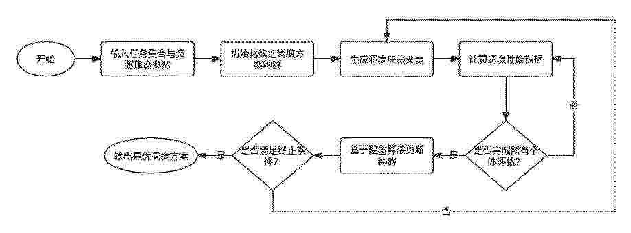
Resumen de: CN122453071A
本发明属于计算机仿真与优化算法领域,涉及一种基于黏菌算法的多任务协同调度与资源优化方法及系统。所述方法包括:构建多任务与多资源的协同调度模型,建立任务与资源之间的分配关系,并引入时间窗约束、资源容量约束及任务优先级约束;对调度方案进行编码表示,将其映射为可搜索的解空间;构建包含任务完成时间、运行成本及资源能耗的多目标优化模型,并通过动态权重实现多目标协调优化;采用黏菌算法进行迭代求解,通过适应度评估、权重更新及位置调整优化调度方案,并结合自适应参数调节与随机扰动提高求解性能;在满足终止条件后输出最优或近似最优调度方案。本发明可提高资源利用效率与调度性能,适用于复杂系统调度优化。
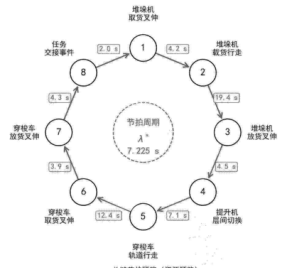
Resumen de: CN122453025A
本发明公开了一种面向WMS的高密度立体仓储动态货位分配方法,涉及人工智能技术领域,立体仓储沿巷道方向布置堆垛机、穿梭车与提升机,立体仓储边缘节点设有现场可编程门阵列加速核,加速核与WMS通过时间敏感网络互联,包括以下步骤:步骤1,加速核基于WMS当前下发的搬运指令构建以搬运动作为事件节点、以动作衔接关系为有向边的节拍依赖图;步骤2,加速核构建着色Petri网;步骤3,加速核构建图注意力强化学习决策模块并以异构图作为输入,由WMS驱动相应搬运设备执行入库、移库或补货动作。本发明能够在亚毫秒级端到端决策延迟下显著提升系统吞吐能力、降低设备空闲率与节拍抖动。
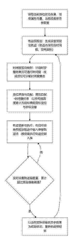
Resumen de: CN122453047A
本发明公开了一种立体库货位分配优化的方法、系统、设备及介质,涉及智能仓储与物流调度技术领域,包括:在设备执行入库作业的过程中,实时采集设备实际轨迹点与设备预规划轨迹之间的轨迹偏差量,当所述轨迹偏差量累计超过预设偏差阈值时,以当前实际设备状态参数集为初始状态,跳转至步骤S2重新进行轨迹预规划和货位分配。本发明通过实时采集设备实际轨迹点与预规划轨迹之间的轨迹偏差量,在累计偏差超阈值时以当前实际设备状态参数集为初始状态触发重规划,形成闭环偏差反馈机制,有效保障系统运行的鲁棒性与动态适应性。
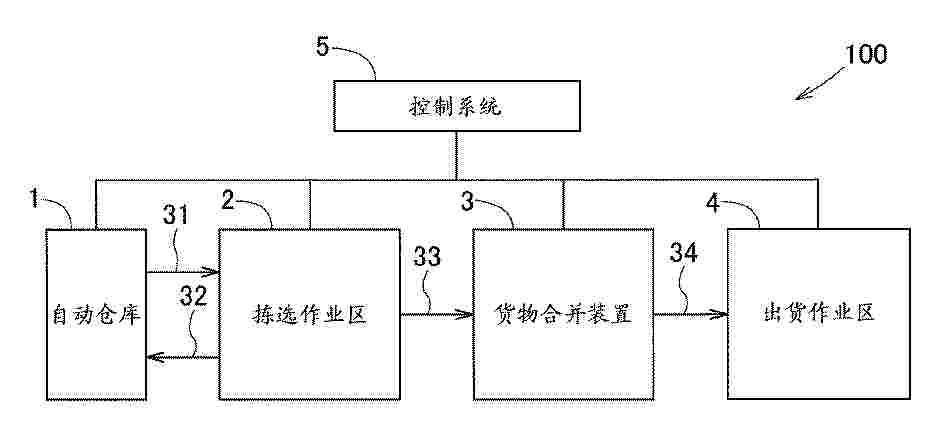
Resumen de: US20260208956A1
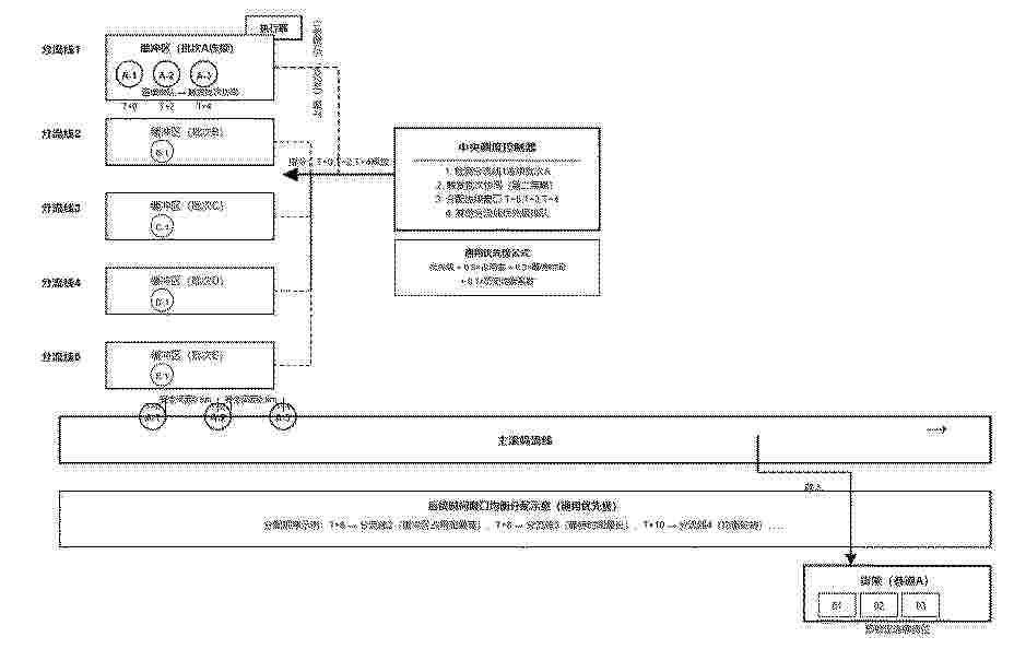
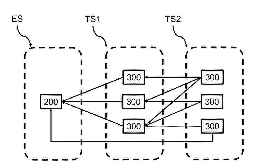
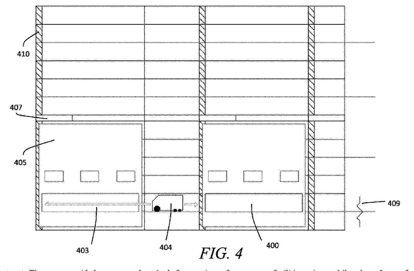
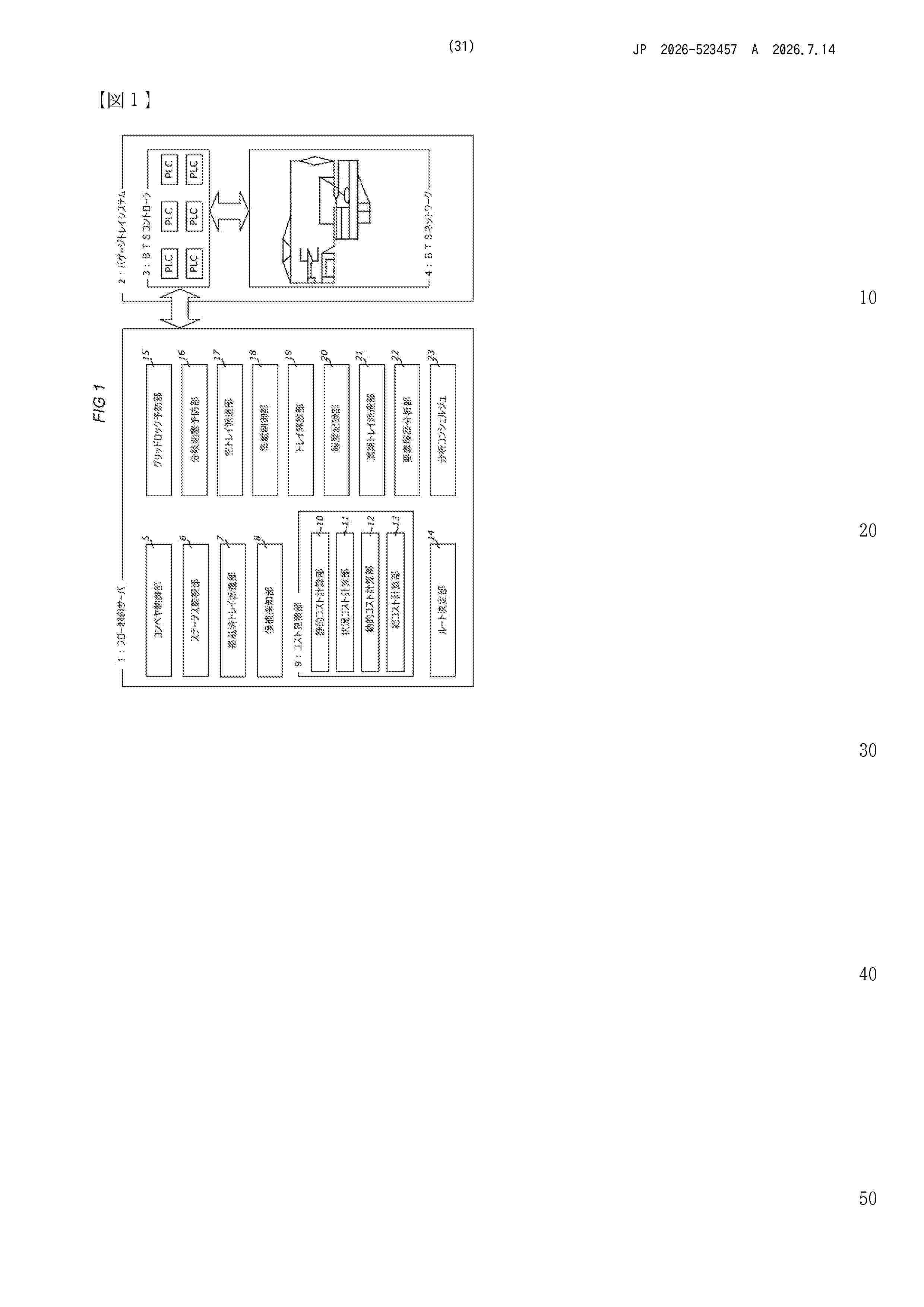
0000 An article shipment system includes an automated warehouse, a picking area, a consolidation area, and a control system. The control system alternately provides, to the automated warehouse, a transfer command to transfer a target mount with a higher picking workload from the automated warehouse and a transfer command to transfer a target mount with a lower picking workload from the automated warehouse to transport multiple first mounts to the picking area. The target mount is a first mount, among the first mounts, loaded with articles of a specified type included in a target article-specific order information group. The target article-specific order information group is a group of pieces of article-specific order information included in part of multiple pieces of order information among pieces of article-specific order information included in the multiple pieces of order information.
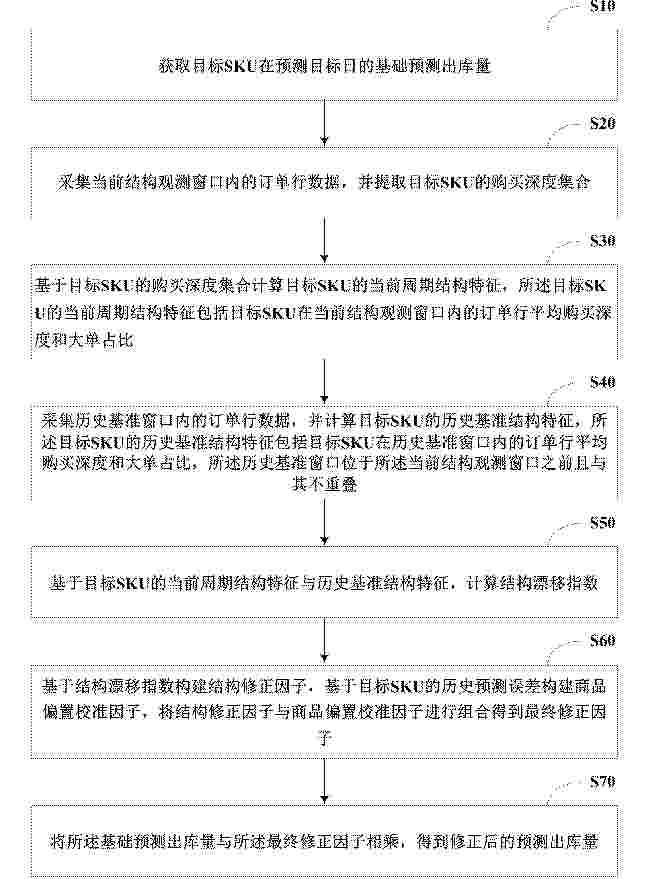
Resumen de: CN122453329A
本发明公开了一种基于漂移检测的出库量预测后处理修正方法及相关设备。本发明通过引入订单行级别的结构信号,弥补了现有预测模型在微观结构感知方面的盲区,解决了现有技术无法感知订单行购买结构变化的问题;通过检测订单行购买深度结构的漂移趋势,对基础预测偏差进行修正,显著降低因购买结构变化导致的系统性误差,提高了预测准确度;采用后处理修正的技术路线,无需改变现有预测模型的架构、训练过程和部署方式,具有良好的工程兼容性和低实施成本;兼顾短期结构变化与长期商品偏差,本发明不仅利用订单行购买深度结构漂移对短期波动进行修正,还通过目标SKU历史偏置校准因子补偿长期稳定高估或低估误差,从而提升预测结果的长期稳定性。
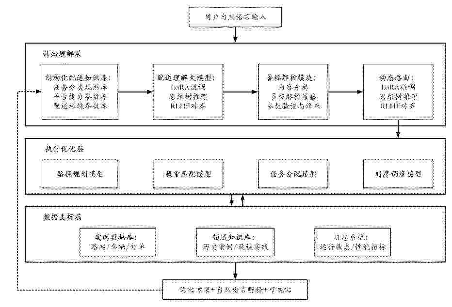
Resumen de: CN122452994A
本发明涉及一种基于大小模型协同的智能配送优化方法及系统,属于人工智能技术领域。本发明通过引入配送任务理解大模型的自然语言理解能力,使普通用户可以直接用自然语言描述配送需求,无需专业人员进行手工建模,大大降低了使用门槛,同时具有良好的泛化能力,能够处理之前未见过的新型配送场景。进一步,本发明不依赖大量标注数据进行端到端训练,而是通过大模型的预训练知识和RAG机制获取领域能力;同时利用大模型的自然语言生成能力为优化方案提供详细的解释说明,解决了深度学习方法可解释性差的问题。
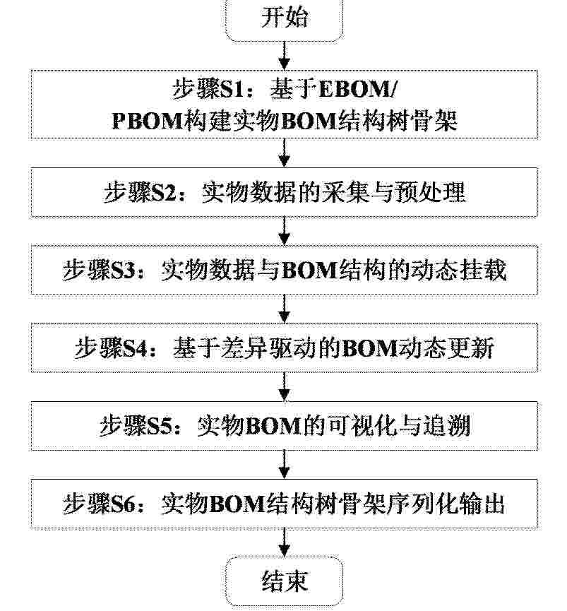
Resumen de: CN122453332A
本发明公开一种面向复杂装备的实物BOM构建方法及系统,涉及产品生命周期管理技术领域,包括:对EBOM结构树和PBOM结构树构建映射矩阵;以EBOM结构树为基础骨架,遍历EBOM节点,对每一EBOM节点,若在映射矩阵中存在对应的PBOM节点,则将对应的PBOM节点的属性附加到当前EBOM节点;若不存在,则保留当前EBOM节点,得到初始种子树;根据PBOM结构树的工艺装配顺序和节点类型,对初始种子树进行结构调整,执行冲突消解与去重,得到实物BOM结构树骨架;对实物BOM结构树骨架填充实物数据,得到实物BOM结构树,且采用树结构差异比对方法进行更新。实现从数字BOM到实物BOM的映射转换与动态同步。
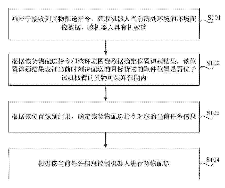
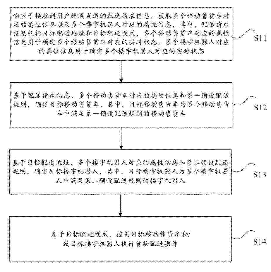
Resumen de: CN122453279A
本公开涉及一种货物配送方法及存储介质。响应于接收到货物配送指令,获取机器人当前所处环境的环境图像数据,所述机器人具有机械臂;根据所述环境图像数据和所述货物配送指令确定位置识别结果,所述位置识别结果表征当前时刻待配送的目标货物的取件位置是否位于所述机械臂的货物可装卸范围内,根据所述位置识别结果,确定所述货物配送指令对应的当前任务信息,根据所述当前任务信息控制所述机器人通过机械臂进行货物配送。这样,无需对电梯、闸机等进行物联网改造,即可通过机械臂模拟人手实现货物的跨楼层配送,节省成本。
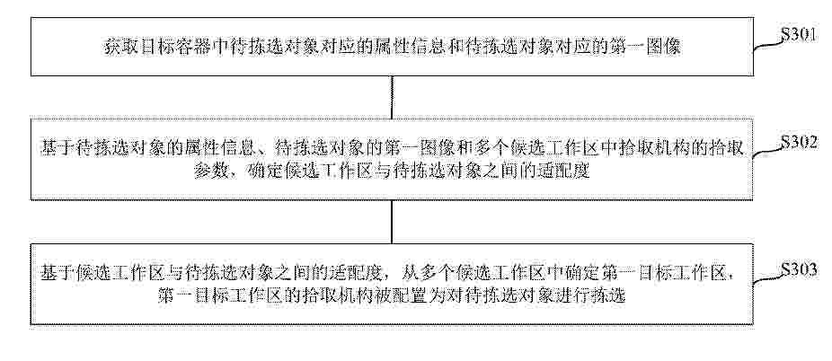
Resumen de: CN122453310A
本发明涉及智能仓储领域,公开了一种工作区确定方法、装置和仓储系统,通过获取目标容器中待拣选对象对应的属性信息和待拣选对象对应的第一图像,并基于待拣选对象的属性信息、待拣选对象的第一图像和多个候选工作区中拾取机构的拾取参数,确定候选工作区与待拣选对象之间的适配度;最后,基于候选工作区与待拣选对象之间的适配度,从多个候选工作区中确定第一目标工作区,通过第一目标工作区的拾取机构对待拣选对象进行拣选。如此确定的第一目标工作区,将更加符合待拣选对象的拣选要求,从而能够提高对待拣选对象的拣选准确性和拣选效率,提高拣选效率。
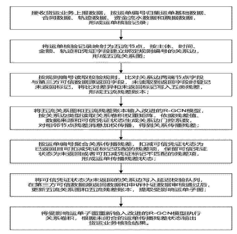
Resumen de: CN122453294A
本发明公开了一种基于大数据分析的货运业务核验方法及系统,包括如下步骤:归集运单、合同、轨迹、资金和票据数据,形成运单核验记录;映射五流节点并建关系边,形成五流关系图;按规则比对可信数据,形成五流残差账本;输入改进的R‑GCN模型,生成门控系数并传播残差;聚合残差并执行扣减或保留,形成传播残差状态;对未返回凭证入延迟队列,回写更新并提取子图;对子图重算关系卷积,输出核验结果。本发明涉及货运业务数据核验技术领域,提高了货运核验准确性和异常追溯效率,降低了人工复核成本。
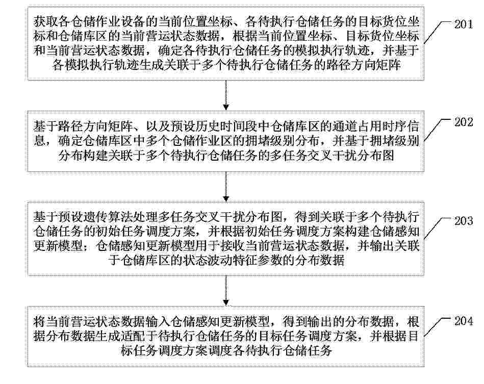
Resumen de: CN122453313A
本申请涉及一种仓储任务调度方法、装置、计算机设备和可读存储介质,涉及仓储调度技术领域,方法包括:获取仓储作业设备位置坐标、目标货位坐标及运营状态数据,用以生成路径方向矩阵;将路径方向矩阵融合仓储库区的通道占用时序信息构建多任务交叉干扰分布图;基于多任务交叉干扰分布图实现对于仓储感知更新模型的构建;将运营状态数据输入仓储感知更新模型,生成目标任务调度方案,依目标任务调度方案执行待执行仓储任务的调度,得到仓储作业的动态调度结果;能够实现仓储运营状态的实时感知、多任务冲突的精准规避及路径与资源的自适应优化,提升仓储任务调度的精准度与效率。
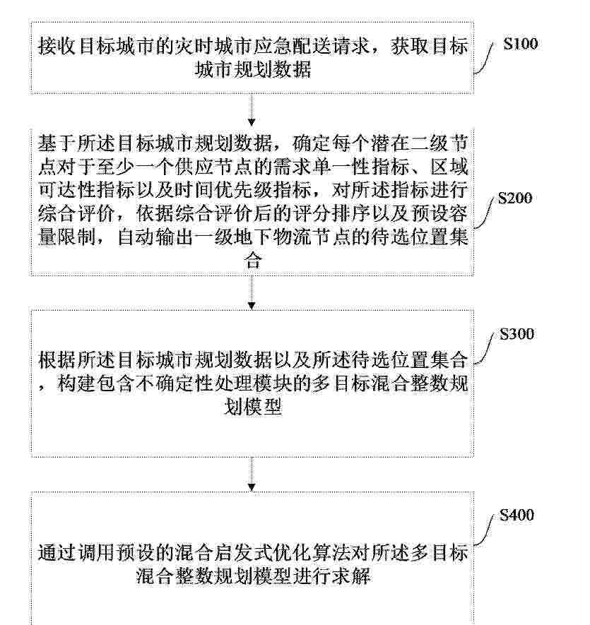
Resumen de: CN122453280A
本申请实施例提供一种地下物流系统布局方法、装置、计算机设备和存储介质,所述方法包括:接收目标城市的灾时城市应急配送请求,获取目标城市规划数据;基于目标城市规划数据,确定每个潜在二级节点对于至少一个供应节点的需求单一性指标、区域可达性指标以及时间优先级指标,对所述指标进行综合评价,依据综合评价后的排序以及预设容量限制,输出一级地下物流节点的待选位置集合;根据所述目标城市规划数据以及所述待选位置集合,构建多目标混合整数规划模型;通过调用预设的混合启发式优化算法对所述多目标混合整数规划模型进行求解,能够在参数不确定的条件下,协同优化节点选址、管道路径和货流分配方案,并兼顾系统效用、效率与公平性。
Resumen de: CN122447916A
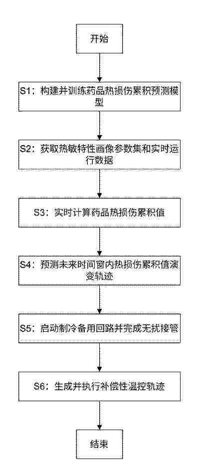
本发明公开了一种基于药品热敏特性的制冷温控安全冗余切换方法,包括以下步骤:S1、构建并训练药品热损伤累积预测模型,确定模型核心参数及各输入特征权重;S2、获取冷藏药品的热敏特性画像参数集和冷藏空间的实时运行数据;S3、通过所述预测模型、参数集及实时运行数据实时计算药品热损伤累积值,本发明涉及药品冷链储存技术领域。该一种基于药品热敏特性的制冷温控安全冗余切换方法,当热损伤演变轨迹逼近安全边界,提前启动备用回路并无扰接管,避免药品温度异常,保障冷藏连续稳定,切换中精准控制参数,将温度波动偏差控制在阈值内,减少对药品影响,提升制冷系统可靠安全。
Resumen de: CN122450998A
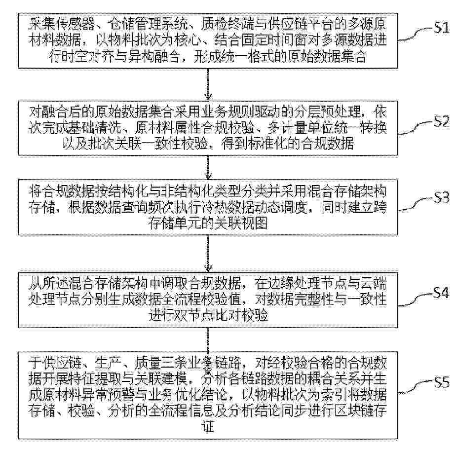
本发明公开了一种原材料数据的处理方法,包括采集多源原材料数据后,以物料批次与固定时间窗完成时空对齐与异构融合,对融合数据执行业务规则驱动的分层预处理,再通过混合存储架构结合冷热数据调度完成分类存储并构建跨存储关联视图,基于供应链、生产、质量三链路构建耦合模型完成关联分析与预警,最后通过边云双节点校验与区块链存证保障数据安全可追溯。有效解决了原材料多源数据融合精度低、预处理适配性差、存储分析低效及数据易篡改的问题,提升了数据处理效率与可用性,实现原材料数据全生命周期可追溯,适用于工业生产、供应链管理与质量监控场景。
Resumen de: CN122452978A
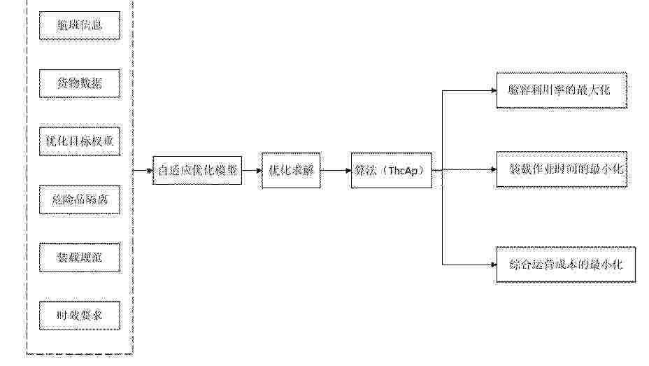
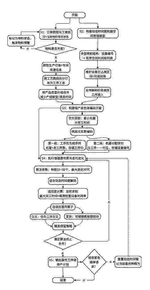
本发明公开一种基于自适应约束放松的民航物流智能配载系统,包括:数据输入与预处理模块、约束多目标建模模块、三种群协同进化优化模块以及方案输出与应用模块;所述数据输入与预处理模块,用于从航空公司运营数据库中提取配载任务所需的多源数据,对数据进行整理、转换为系统可读格式并载入系统缓存区,完成模型的数据准备;所述约束多目标建模模块,用于基于数据输入与预处理模块输出的数据,构建民航物流智能配载的约束多目标优化模型;所述三种群协同进化优化模块,采用三种群协同进化算法ThcAp为核心求解器。本发明约束处理更灵活智能多目标优化能力更强,算法鲁棒性更高,场景适应性,配载效率与综合效益显著提升。
Resumen de: CN122453321A
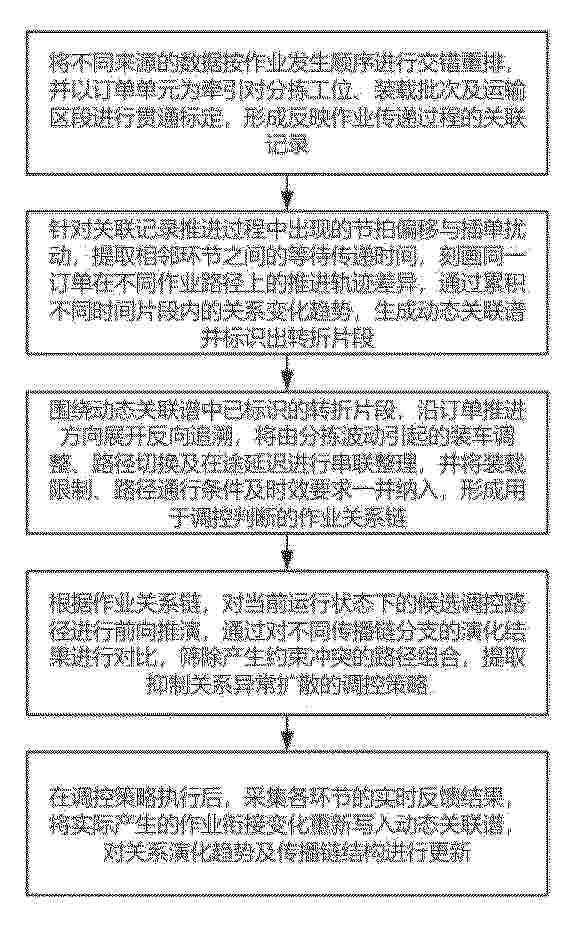
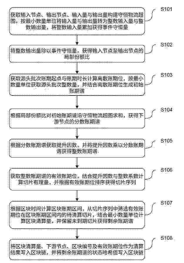
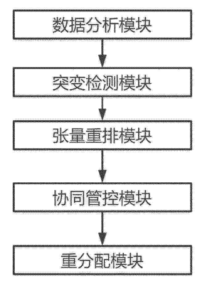
本发明涉及知识图谱领域,且公开了一种物流作业环节联动调控系统及方法,包括将不同来源的数据按作业发生顺序进行交错重排,并以订单单元为牵引对分拣工位、装载批次及运输区段进行贯通标定;针对关联记录推进过程中出现的节拍偏移与插单扰动,提取相邻环节之间的等待传递时间,刻画同一订单在不同作业路径上的推进轨迹差异;围绕动态关联谱中已标识的转折片段,将由分拣波动引起的装车调整、路径切换及在途延迟进行串联整理;对当前运行状态下的候选调控路径进行前向推演,筛除产生约束冲突的路径组合;采集各环节的实时反馈结果,将实际产生的作业衔接变化重新写入动态关联谱。本发明具备提升多环节联动调控准确性的优点。
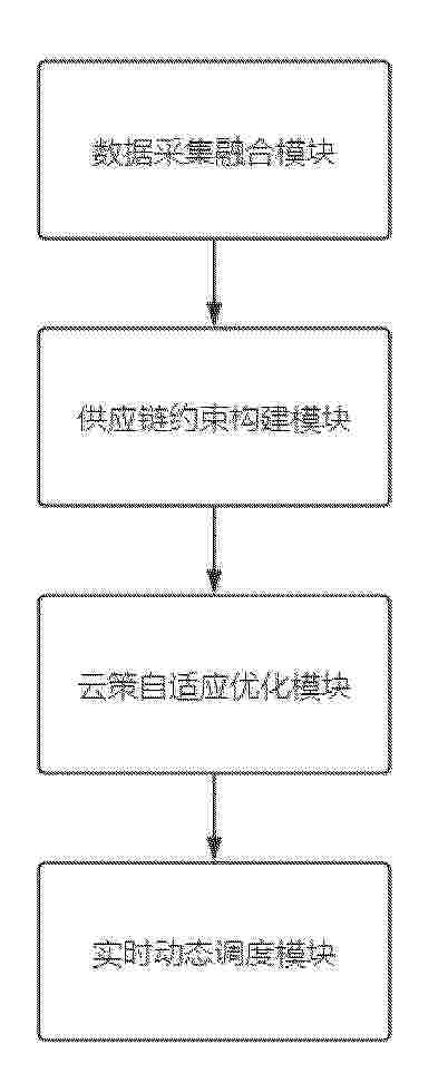
Resumen de: CN122453039A
本发明公开了一种基于云计算的煤炭运输调度方法和系统,涉及运输调度技术领域,该系统由若干功能模块组成,包括:数据采集融合模块,通过多源数据采集终端,采集煤炭生产、运输、仓储、需求及外部环境的全链条数据,通过预设的语义映射规则与动态适配器对不同数据源进行自适应解析与语义统一,生成标准化供应链时序数据集;供应链约束构建模块,通过云端数据融合引擎,对标准化供应链时序数据集进行多维度清洗、关联与特征提取,获得可用于建模的全局特征数据;云策自适应优化模块,基于优化供应链协同调度模型,将全局特征数据作为输入,输出最优协同调运计划。
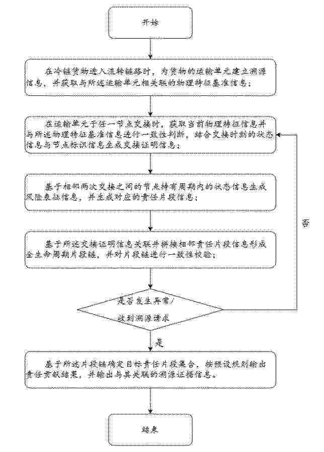
Resumen de: CN122453300A
本发明公开了一种冷链货物全生命周期溯源的物联网管理方法及管理系统,涉及冷链物流物联网管理技术领域,技术方案为,在冷链货物进入流转链路时建立运输单元溯源信息并获取物理特征基准信息;在各节点交接时获取当前物理特征并与基准进行一致性判断,结合状态信息与节点标识信息生成交接证明信息;基于节点持有周期状态信息生成风险表征信息及责任片段信息;基于交接证明信息拼接责任片段形成全生命周期片段链并进行一致性校验;在异常或溯源请求时输出责任贡献结果及溯源证据信息。本发明的有益效果是:提升运输单元同一性验证能力和交接证据不可否认性,实现节点持有周期风险量化与责任片段化管理,提高溯源链连续性、一致性及异常追责效率。
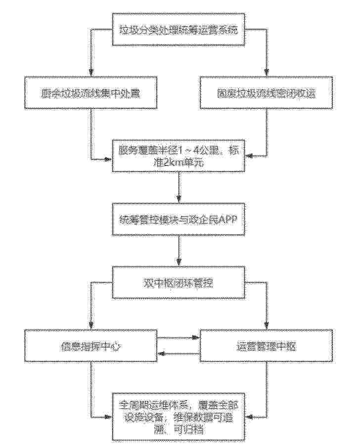
Resumen de: CN122453088A
本发明公开了一种垃圾分类处理区域统筹运营基本单元系统,属于垃圾分类处理区域统筹运营技术领域,包括按垃圾类型分为厨余垃圾、固废垃圾两条处理流线,两线独立运行且数据互通,基本单元覆盖半径为1~4公里,常用标准半径为2公里;厨余垃圾可单小区独立处理,多相邻小区经密闭管网汇流集中处置;固废垃圾可单小区独立收集,多相邻小区分类归集后密闭收运至收集站、处置场所;设有可整合分体设置的统筹管控模块,搭配政企民APP作为统一交互端口;本发明采用一心两线双中枢架构,搭配统一政企民APP交互端口,形成决策、执行、反馈、优化全闭环管理;多方主体数据互通,传输延迟≤2秒,物联网高频采集数据,系统运行稳定、业务联动高效。
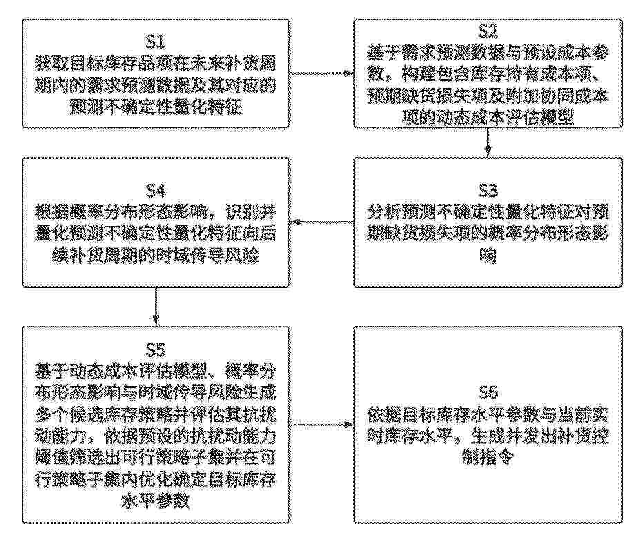
Resumen de: CN122453314A
本发明公开了物流仓储库存需求预测与智能补货管理方法,具体涉及工业控制系统技术领域,用于解决现有基于固定规则的补货控制策略在面对需求不确定性时存在的鲁棒性失衡缺陷,导致库存成本与服务水准难以稳定优化的问题;是通过获取需求预测数据及其不确定性量化特征,构建融合库存成本、缺货风险及仓储资源协同成本的动态评估模型,分析不确定性对缺货损失概率分布的影响并识别其时域传导风险,进而生成候选库存策略并评估其抗扰动能力,依据抗扰动能力阈值筛选出可行策略后优化确定目标库存水平,最终生成补货控制指令来实现的;使工业控制系统能够输出兼具经济性与鲁棒性的补货策略,实现库存成本的稳定控制。
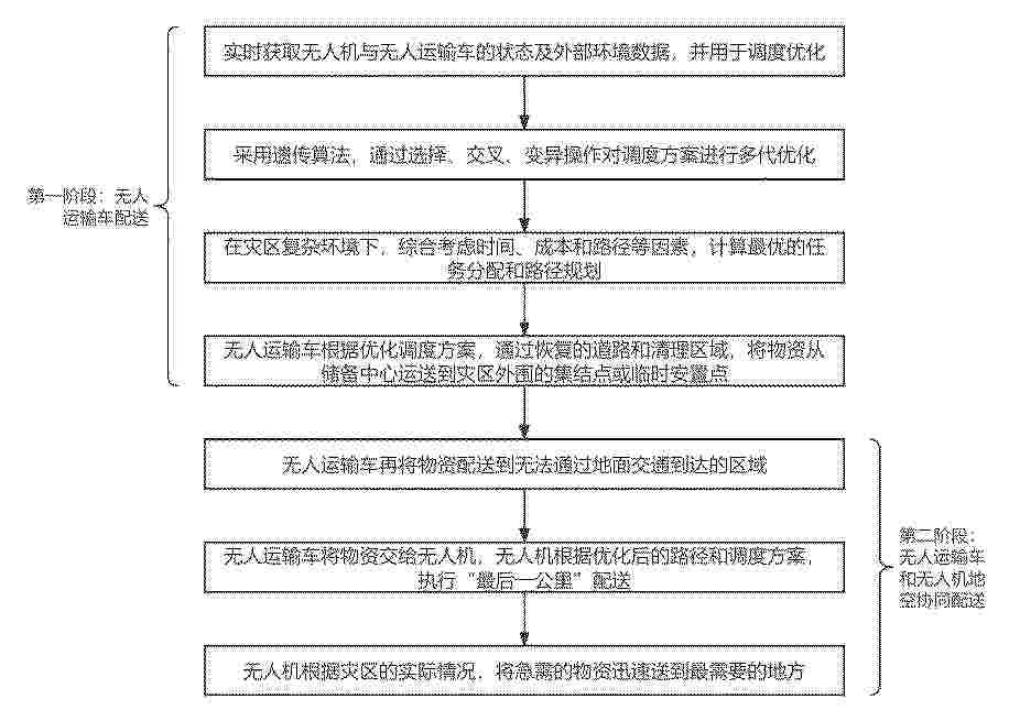
Resumen de: CN122453283A
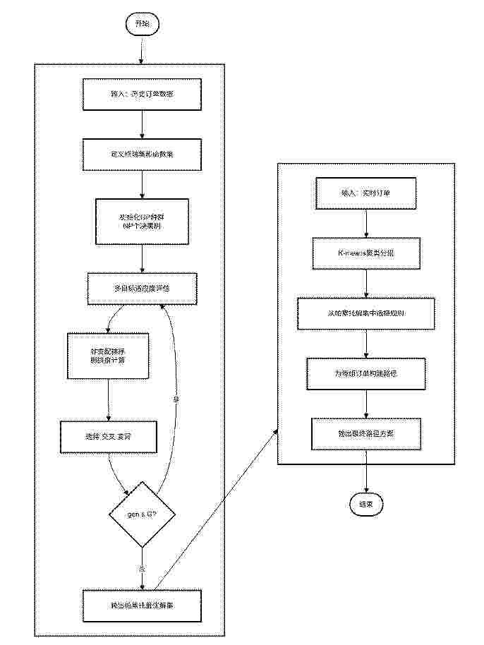
本发明公开了一种紧急物资的地空协同配送智能调度方法与系统,该方法首先实时获取无人机与无人运输车的状态信息及外部环境信息;利用获取的信息建立调度方案,采用遗传算法对调度方案进行多代优化;综合考虑配送时间、运输成本、路径长度多个性能指标,计算出最优的任务分配和路径长度规划;无人运输车根据优化后的调度方案,将物资从物资储备中心运送到灾区外围的集结点或临时安置点;无人机将物资从集结点或临时安置点精准投递到目标区域。通过采用“无人运输车配送+无人机末端投递”的两阶段模式执行配送任务,能够精准制定适配灾区环境的调度方案并高效执行,有效提升地震灾区紧急物资配送的及时性与精准度。
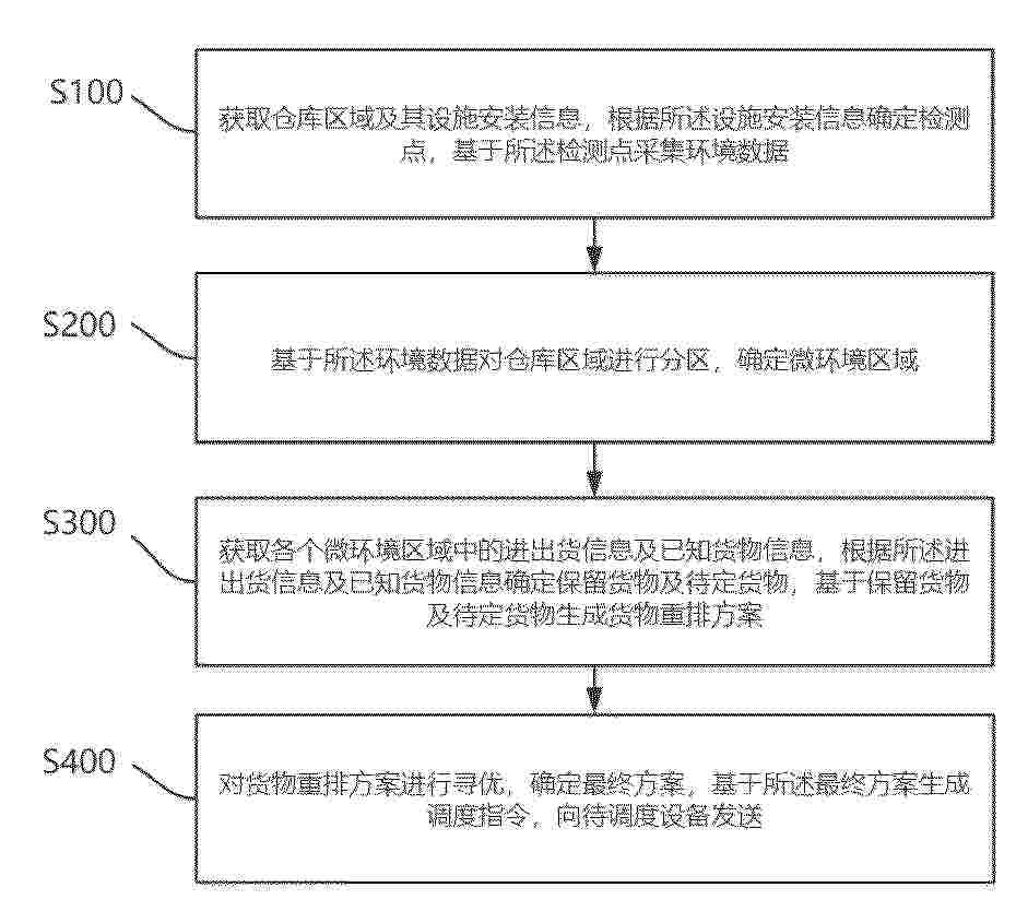
Resumen de: CN122453325A
本发明适用于仓库智能管理技术领域,尤其涉及基于物联网的智慧仓库全流程调度方法及系统,所述方法包括获取仓库区域及其设施安装信息,根据所述设施安装信息确定检测点,基于所述检测点采集环境数据;基于所述环境数据对仓库区域进行分区,确定微环境区域;获取各个微环境区域中的进出货信息及已知货物信息,根据所述进出货信息及已知货物信息确定保留货物及待定货物,基于保留货物及待定货物生成货物重排方案;对货物重排方案进行寻优,确定最终方案,基于所述最终方案生成调度指令,向待调度设备发送;本发明确定域内的重排路径以及域外的重排路径的过程可以应用多种现有规则,进行随机组合,最终通过寻优过程使方案收敛,灵活度极高。
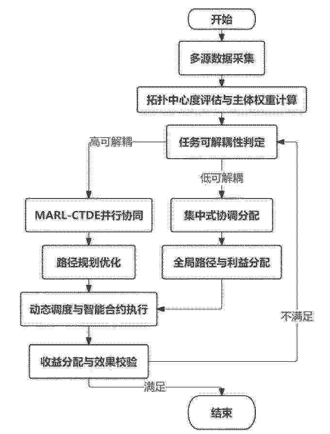
Resumen de: CN122453014A
本发明公开了基于多智能体博弈的山地丘陵生物质收储运协同调度方法及系统,涉及智慧农业与供应链协同技术领域,旨在解决现有技术中利益分配失衡、地形约束忽视及协同机制僵化的问题。本发明首先获取收储节点静态属性数据、动态运营数据及待收运的生物质的所有资源点的地理分布与资源量;确定所有资源点的地理分布的离散度、资源量的均衡度、利益相关方的诉求差异度;将离散度、均衡度、各收储节点的静态属性数据及诉求差异度作为判定指标,根据预设的判定机制确定利益相关方的协同模式,并执行协同规划,完成收集路径及其对应资源的动态规划;最终实现资源动态分配。
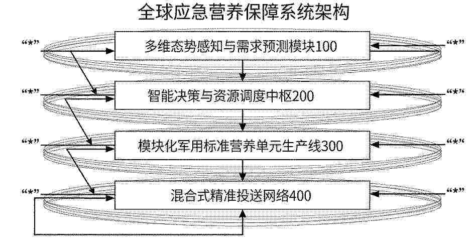
Resumen de: CN122453579A
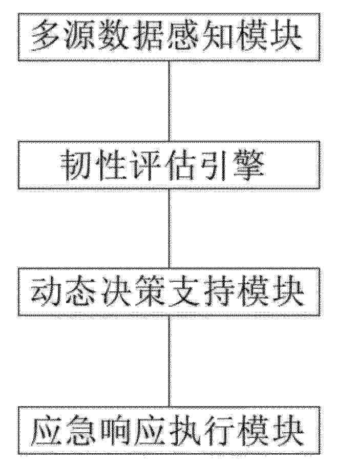
本发明公开了基于军事后勤与态势感知技术的全球应急营养保障系统及方法,该系统由集成军事级战役态势分析模型的多维感知模块、采用平战转换军事后勤架构的智能决策中枢、按国家军用标准(GJB)配置的模块化生产线、以及具备抗干扰能力的混合式精准投送网络构成;所述方法实现了从军事预警模型识别风险,到战役推演生成方案,再到依军用标准生产并依法动员投送的全流程闭环。本发明通过将军事后勤体系进行深度系统性转化,解决了传统粮食援助响应慢、效率低、“最后一公里”覆盖难的问题,提供了响应更快、投送更准、可靠性更高的军民融合创新方案。
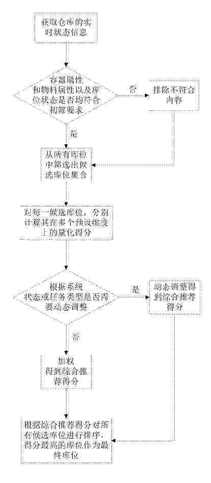
Resumen de: CN122453327A
本发明涉及仓储物流技术领域,公开了一种基于多维度的动态倒库库位确定方法,获取仓库的实时状态信息;基于容器属性和物料属性以及库位状态,从所有库位中筛选出候选库位集合;对每一候选库位,分别计算其在多个预设维度上的量化得分,并将各维度得分根据系统状态或任务类型动态调整得到综合推荐得分;所述预设维度至少包括基于库位两侧邻位占用状态和深位填充优先系数,及操作安全与难度维度;根据综合推荐得分对所有候选库位进行排序,并将得分最高的库位作为最终库位输出。解决了现有技术中策略单一、静态分配、安全性不足、易形成系统瓶颈的问题,达成了全局效率最优、动态自适应、操作安全可靠、系统负载均衡的目的。
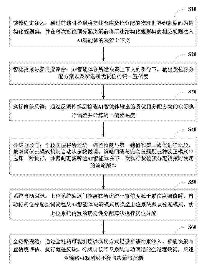
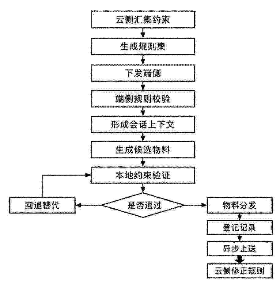
Resumen de: CN122453330A
本发明公开了一种基于四层闭环治理架构的智能货位预分配方法及系统。该智能货位预分配方法包括:前馈引导层将物理世界约束编码为刚性/柔性分离的结构化规则集并注入AI智能体决策上下文;AI智能体输出带统一置信度的货位预分配方案;反馈传感层采集实际执行偏差;自校正层按双阈值三模式机制从参数微调、策略回滚与完全重规划中自动选择校正模式;上位系统回退门控层在统一置信度低于阈值时自动切换至上位系统默认算法;全链路可观测层横切贯穿全程记录数据供审计。本发明通过四层闭环治理架构,解决了AI智能体直接应用于货位分配时缺乏物理约束保障、闭环校正能力及全自动运行安全性的技术问题,适配纯单深、纯双深及混合三种货架构型。
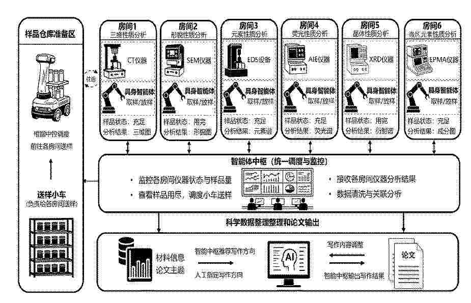
Resumen de: CN122452928A
本发明公开了一种基于智能体驱动的材料分析表征全自动化实验室管理系统,方案包括:各分析房间配置有材料分析仪器及具身智能体,具身智能体执行样品取放操作。智能体中枢统一调度AGV小车在各房间自动运输样品,实时监控仪器状态与样品余量,并整合分析结果执行数据清洗与关联分析。智能体中枢内置智能调度优化模块、异常自检与修复模块、分析依赖管理模块及属性关联推理模块,实现仪器完成时间预测、异常自动重测与故障溯源、依赖属性自动传递及材料属性间潜在关联挖掘。论文写作模块根据整合后的材料数据及用户指定方向自动生成学术论文。本发明实现了材料分析全流程自动化与智能化,适用于高通量材料研发与无人值守实验室场景。
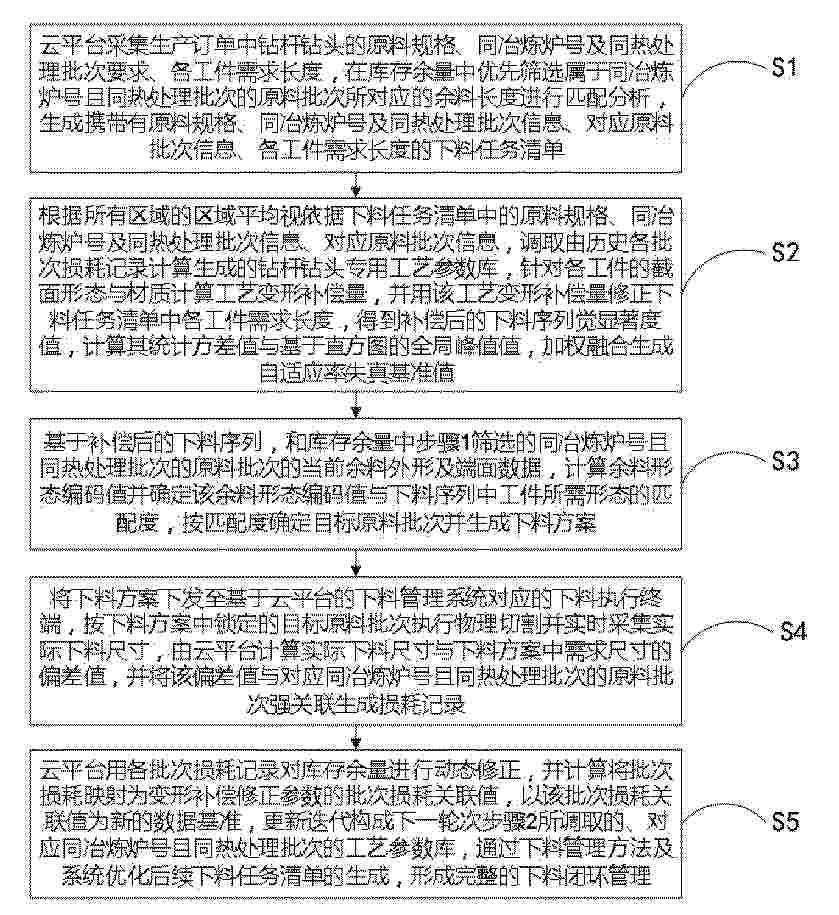
Resumen de: CN122453059A
本发明公开一种基于云平台的下料管理方法及系统,涉及生产管理技术领域。所述方法包括:云平台采集生产订单中钻杆钻头的原料规格、同批号及同热处理批次要求、各工件需求长度,优先筛选同批次余料生成下料任务清单;调取历史损耗生成的工艺参数库计算工艺变形补偿量,修正需求长度得到补偿后序列;基于余料外形数据计算形态编码值,匹配确定目标原料批次生成下料方案;下发方案至执行终端切割并采集实际尺寸,计算偏差生成损耗记录;使用损耗记录动态修正库存并更新工艺参数库,形成闭环管理。本发明能够有效利用同批号原料,通过变形补偿与闭环反馈,显著提高下料精度与原料利用率。
Resumen de: CN122452891A
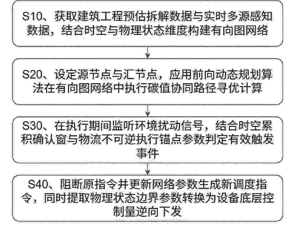
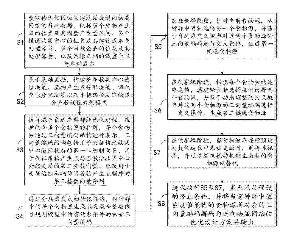
本发明涉及建筑废弃物处理技术领域,公开了一种建筑废弃物资源化路径动态规划方法,包括获取物料清单数据设定基准成分,结合多源异构数据构建有向图网络,节点为包含地理空间坐标、时间窗口和物理状态的三维扩展节点;将废弃物与再生建材应用位置对应节点分作源、汇节点,获取初始最优路径指令;监听包含物料实际成分偏差信号的环境扰动信号,在该信号于时空累积确认窗内超出容忍边界范围且运输车辆未驶过不可逆执行锚点时确认有效触发事件;据此阻断初始指令,将当前地理空间坐标对应的三维扩展节点作为起始计算节点更新网络并生成新调度指令,提取最大物料粒径临界值转换为排矿口设定间隙控制量,下发调整移动破碎设备的初始破碎粒径。
Resumen de: CN122451075A
本公开的实施例公开了应用于智慧物流仓库的信息检索查询方法、装置。该方法的一具体实施方式包括:获取与智慧物流仓库系统进行沟通交互的历史物流交互信息,并对历史物流交互信息进行问答压缩;对压缩物流交互信息进行问答分解,得到分解物流交互信息;对分解物流交互信息进行检索图谱映射,得到物流交互检索图谱;根据物流交互检索图谱进行检索路径聚合,得到检索路径集;根据目标物流问题信息和目标检索路径进行答复检索,得到针对目标物流问题信息的目标物流检索信息;对目标物流问题信息和目标物流检索信息进行持久化存储。该实施方式实现了自然语言意图与智慧物流知识库的精准耦合,提升了智慧物流系统的整体运维智能化水平。
Resumen de: CN122457277A
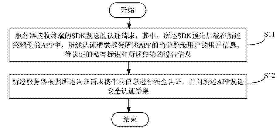
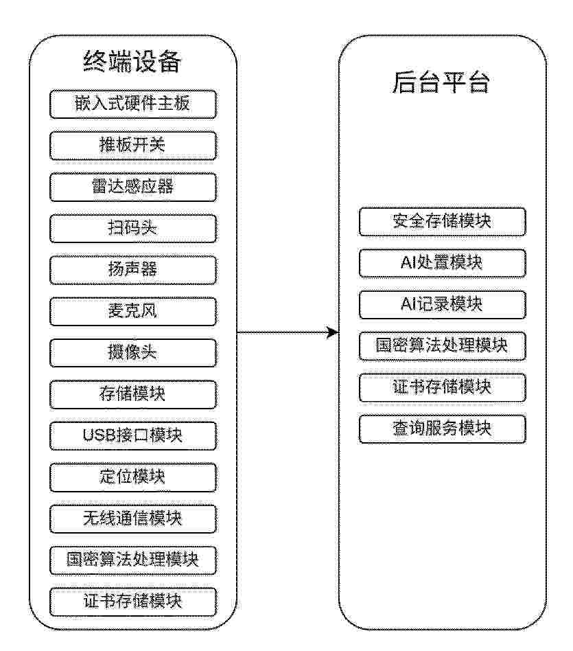
本申请提供了一种安全认证方法、服务器及终端。所述方法在应用于服务器侧时包括以下步骤:服务器接收终端的SDK发送的认证请求,其中,所述SDK预先加载在所述终端侧的APP中,所述认证请求携带所述APP的当前登录用户的用户信息、待认证的私有标识和所述终端的设备信息;所述服务器根据所述认证请求携带的信息进行安全认证,并向所述SDK发送安全认证结果。本申请实施例提供了一种硬件级别的,可以与用户信息及物流信息绑定认证的供应链物流安全认证机制,提高了物流信息的安全性与隐私性。
Resumen de: CN122453005A
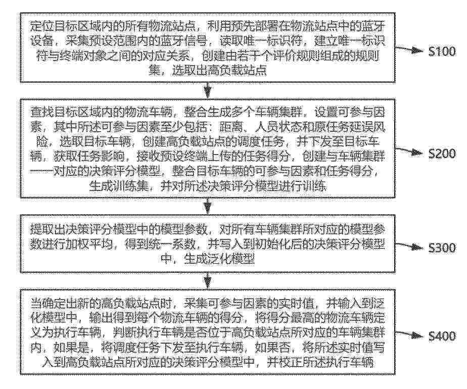
本发明适用于车辆调度技术领域,尤其涉及基于时空数据挖掘的物流车辆集群调度优化方法及系统,所述方法包括:定位目标区域内的所有物流站点,利用预先部署在物流站点中的蓝牙设备,采集预设范围内的蓝牙信号,读取唯一标识符,建立唯一标识符与终端对象之间的对应关系,创建由若干个评价规则组成的规则集,选取高负载站点;查找目标区域内的物流车辆,整合生成多个车辆集群,设置可参与因素。本发明通过统一量化多源数据,消除主观偏差,有效保障调度结果趋于局部最优,通过创建泛化模型,能够实现在不同车辆集群间的车辆调度,实现整个物流网络的协同最优运行,显著提升物流站点的整体运作效率与运行可靠性。
Resumen de: TW202345058A
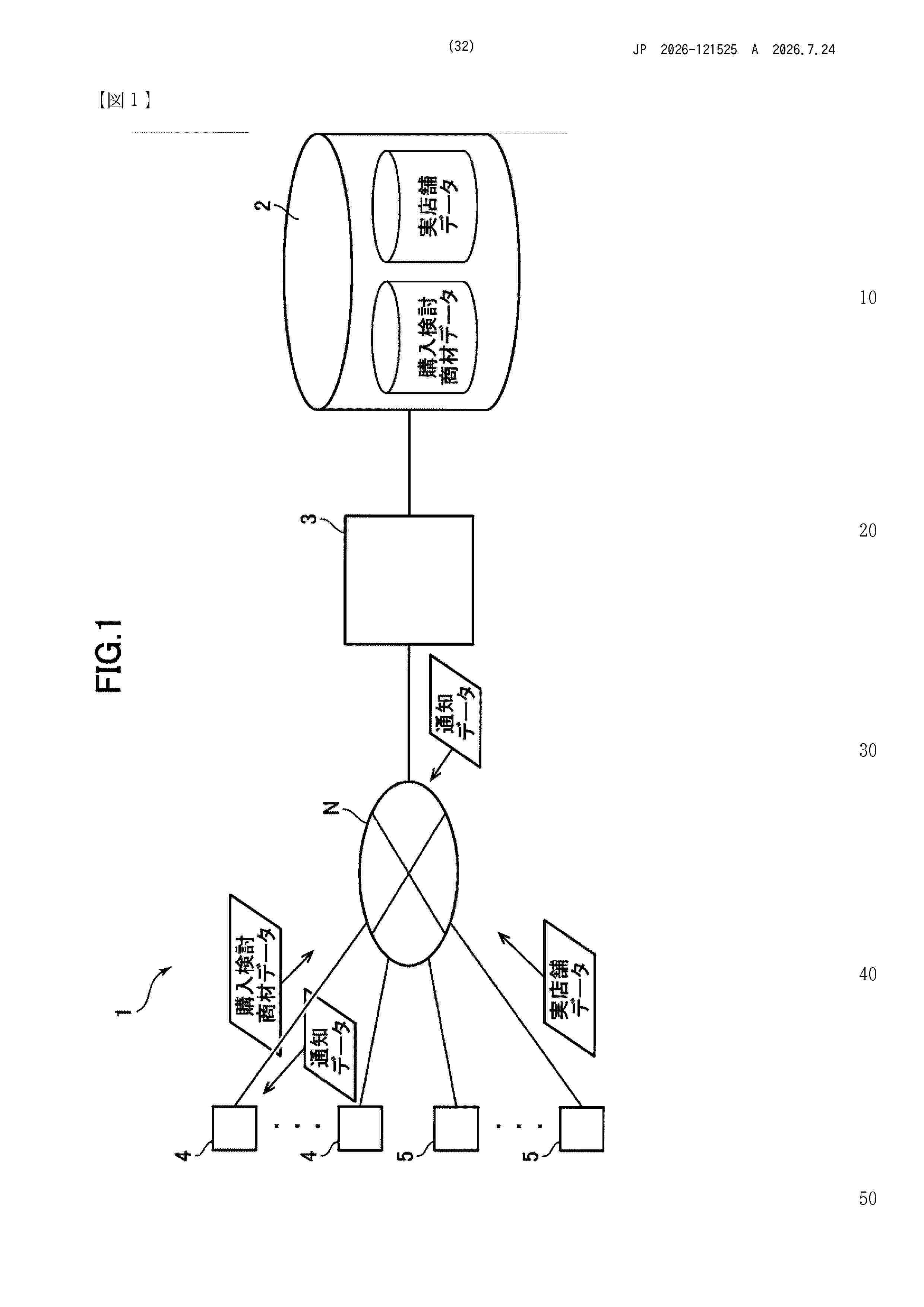
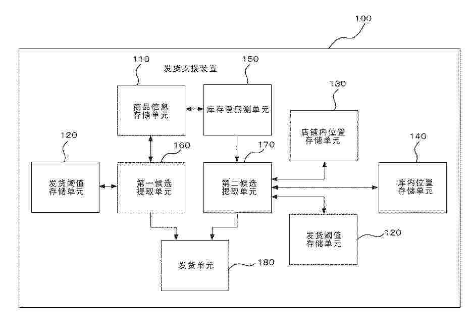
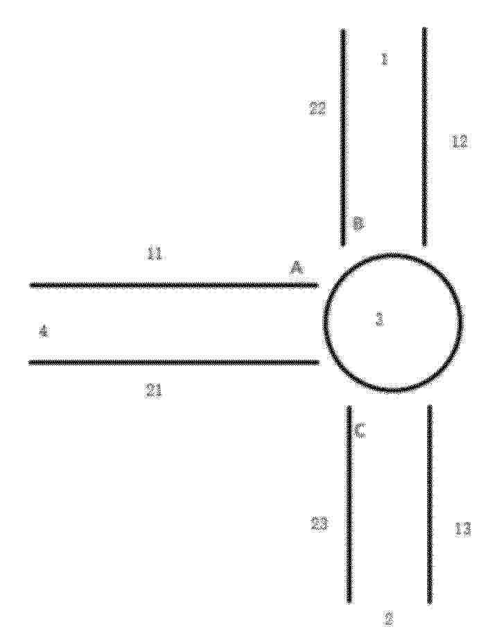
A system, a user terminal program and a server capable of providing a location of a physical store where a user can purchase a purchase consideration merchandise desired by the user among a plurality of physical stores. A server 3 comprises: a determination unit 31a configured to determine whether a merchandise ID of a purchase consideration merchandise and a physical store merchandise ID match; a physical store identification unit 31b configured to identify a physical store that handles the merchandise when the determination unit 31a determines that the merchandise ID of the purchase consideration merchandise and the physical store merchandise ID match; and a transmission unit 35 configured to transmit image data of the merchandise and location information of the physical store to a user terminal 4 when the determination unit 31a determines that the merchandise ID of the purchase consideration merchandise and the physical store merchandise ID match, the physical store identification unit 31b identifies the physical store, and inventory information of the merchandise indicates that the merchandise is in stock; wherein the user terminal 4 includes a display unit 44 that displays a map, and the display unit 44 is configured to display an image of the merchandise based on the image data at a location identified by the location information of the physical store on the map.
Resumen de: JP7317406B1
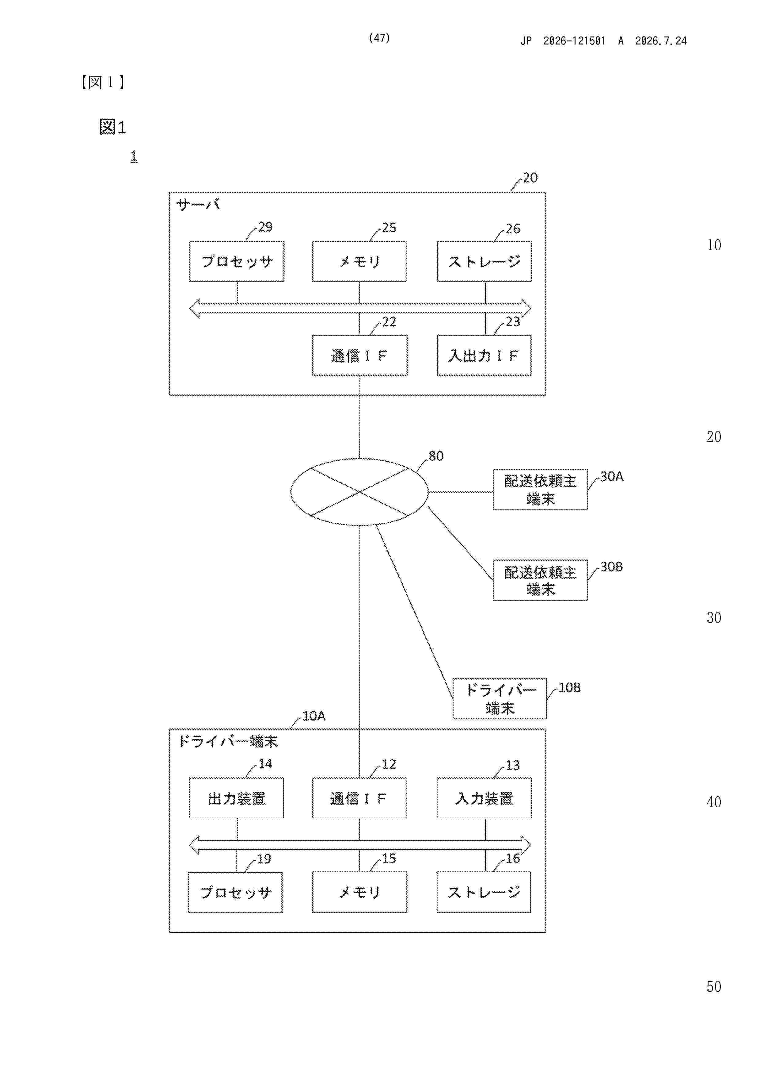
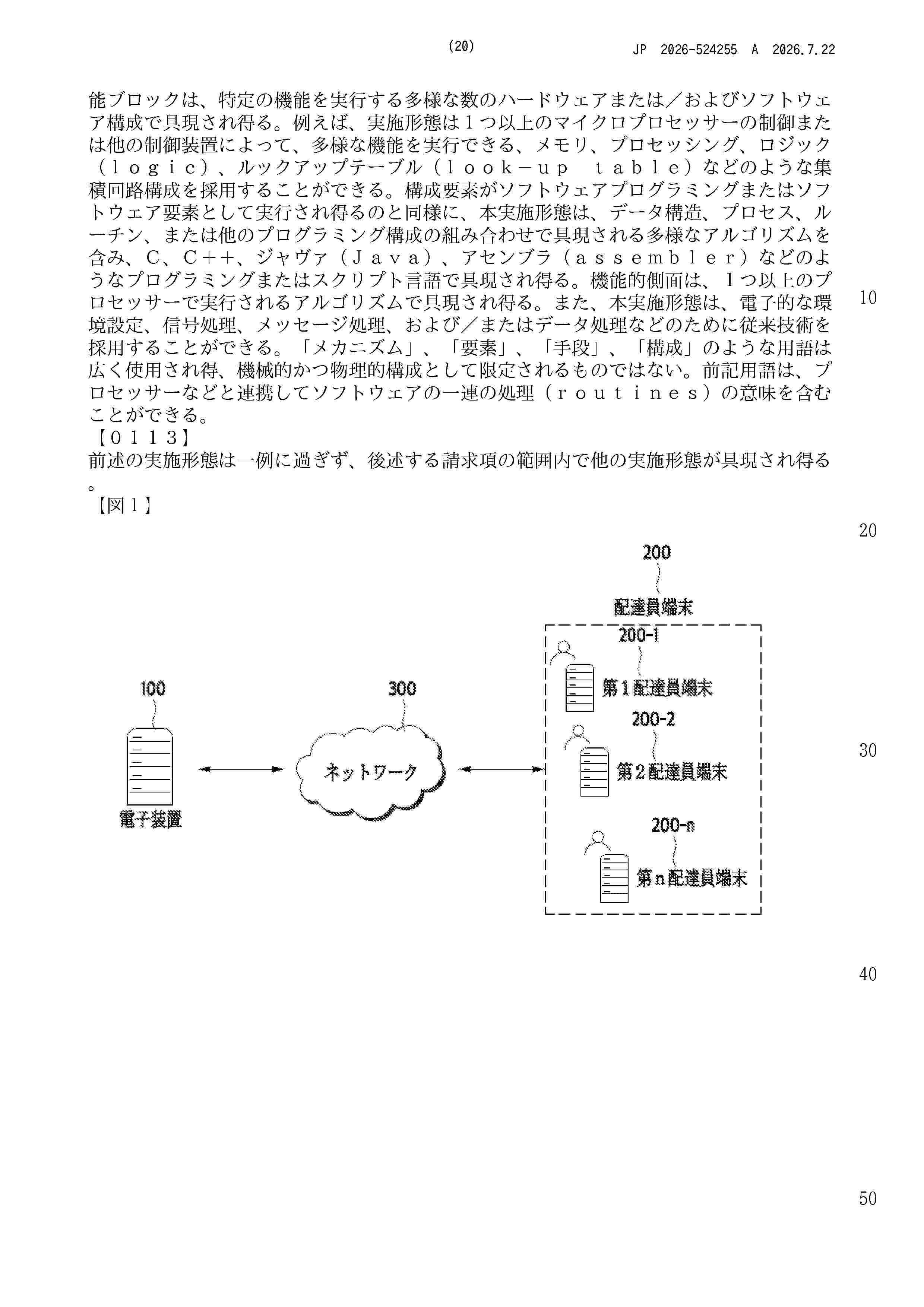
To provide another technique of evaluating a driver for encouraging growth of the driver.SOLUTION: There is provided with a program activating a computer that provides a service of matching a package owner requesting delivery of a package with a driver in charge of delivering the package. The program causes a processor of the computer to execute the steps of: providing each driver with information of a package that a package owner requests for delivery; disclosing to the package owner, driver candidates to whom the package owner may request to deliver the package; recording by the driver, performance of deliveries based on the delivery request; identifying a history of deliveries based on the driver's delivery performance; and determining a first evaluation parameter in the service of matching the driver based on the identified result, where the first evaluation parameter for every driver candidate is disclosed to the package owner.SELECTED DRAWING: Figure 21
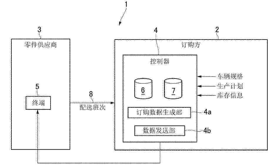
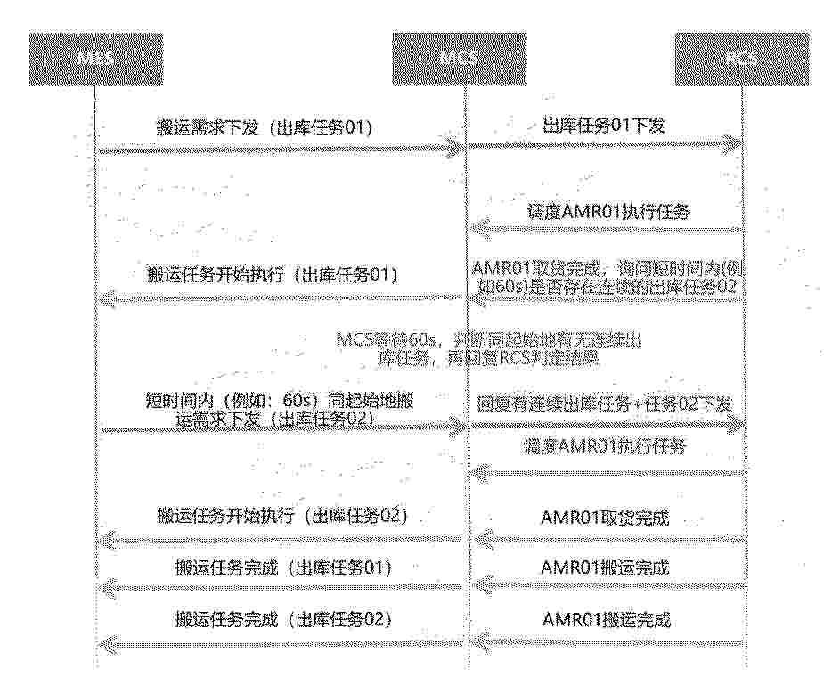
Resumen de: WO2025140801A1
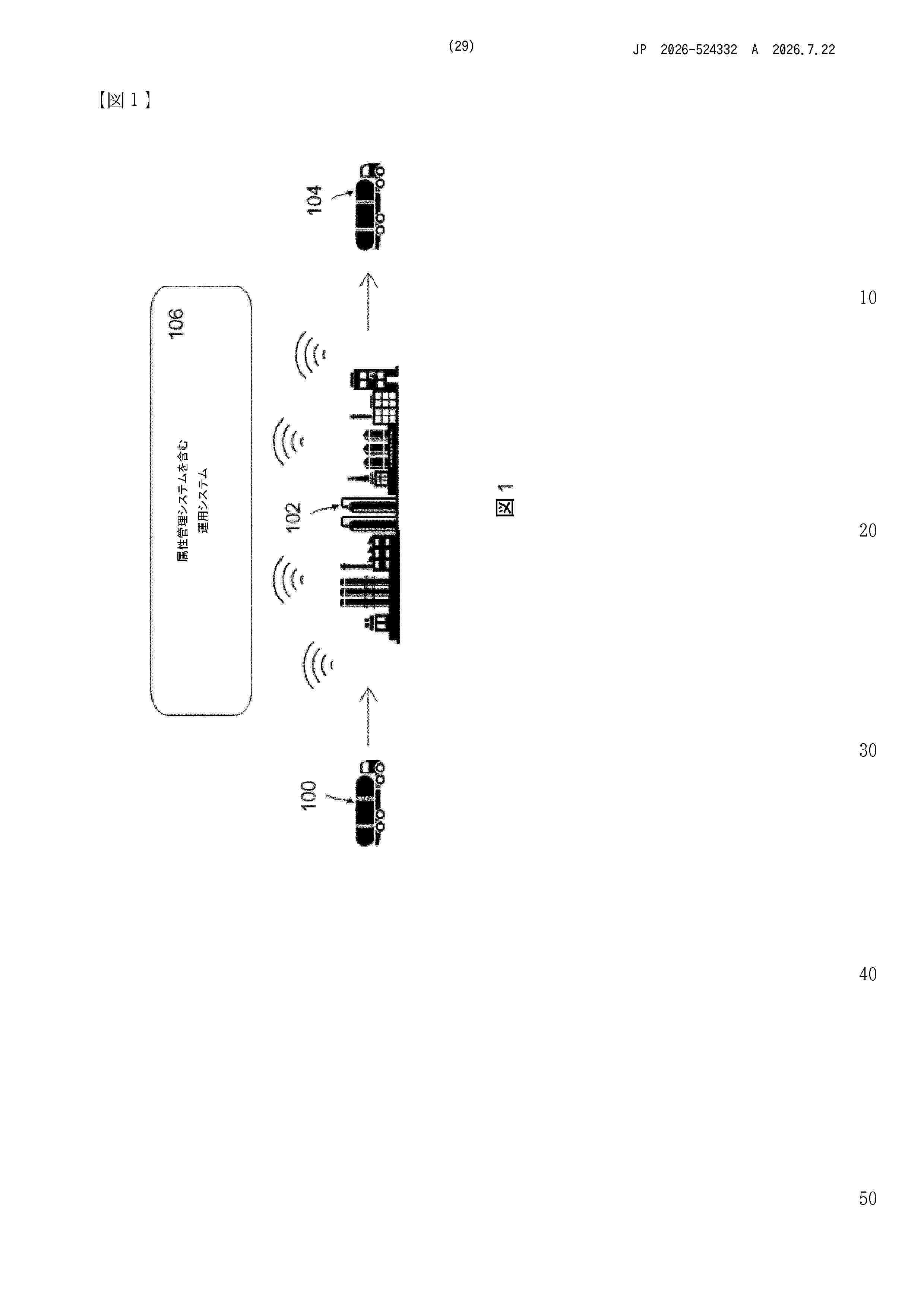
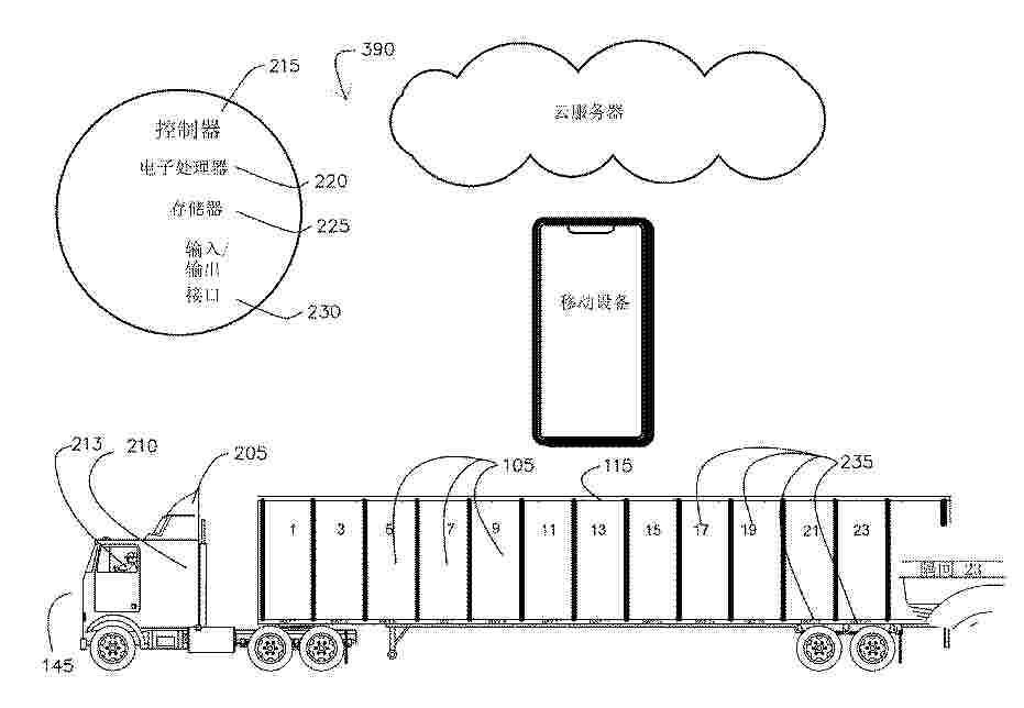
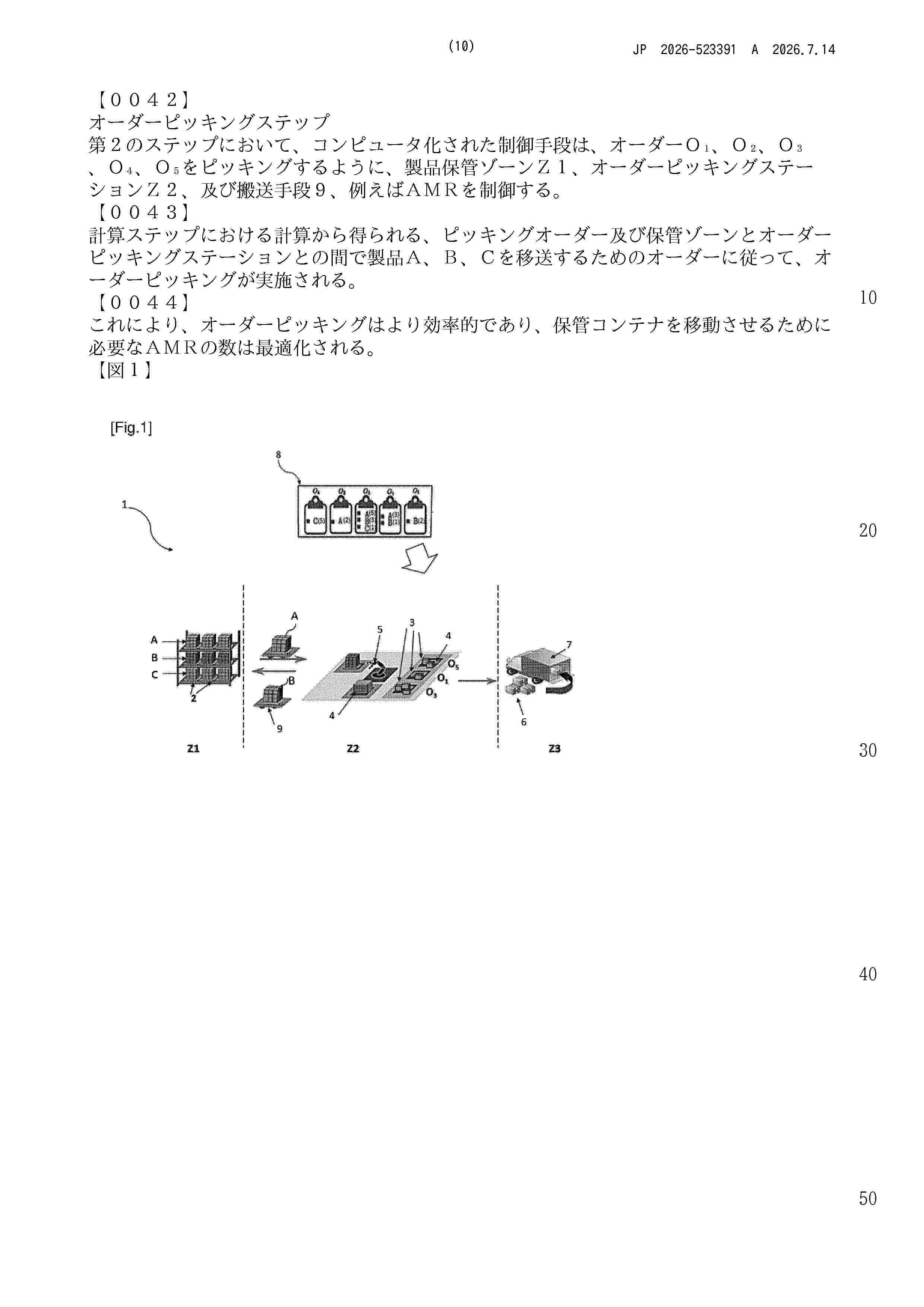
The present disclosure discloses a method and a system for processing an order according to vehicle capacity. The method includes the steps of receiving information of an order proposal from a first remote terminal; determining, based on the information of the order proposal, whether a vehicle utilization of the order proposal meets a preset full-vehicle requirement associated with vehicle capacity; if not, determining a list of recommended products based on the information of the order proposal and sending the list of recommended products to the first remote terminal; and if so, the order proposal is accepted as a full-vehicle order and organizing transportation according to the information of the order. The method can save time and logistic complexity of placing a full-vehicle order for the customer and reduce carbon dioxide emission.
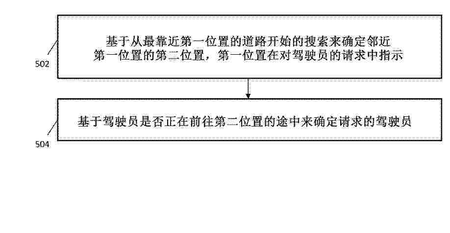
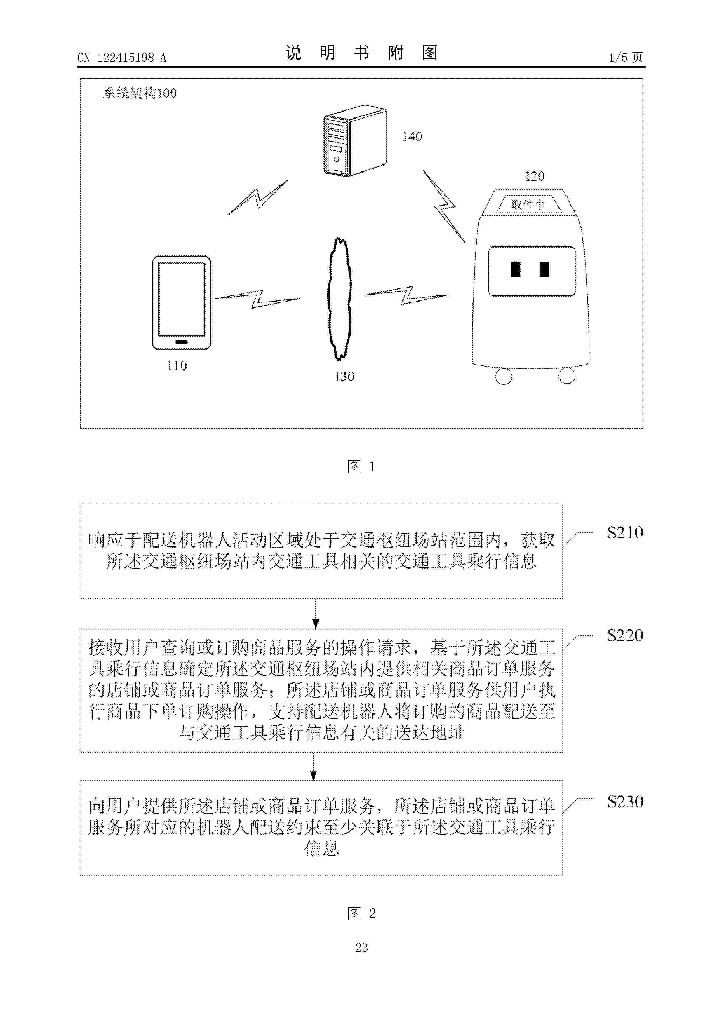
Resumen de: WO2025142168A1
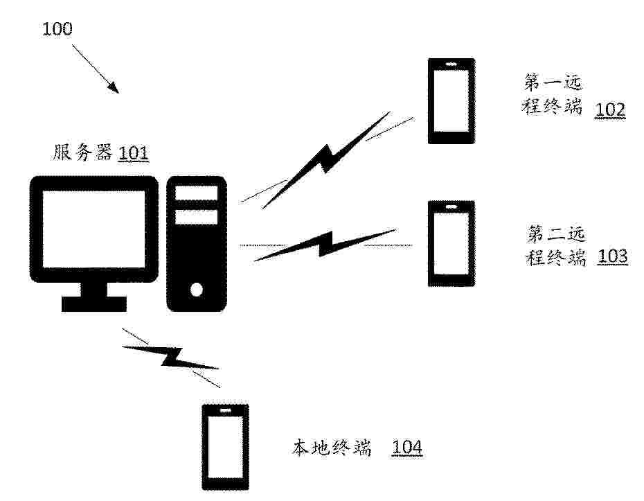
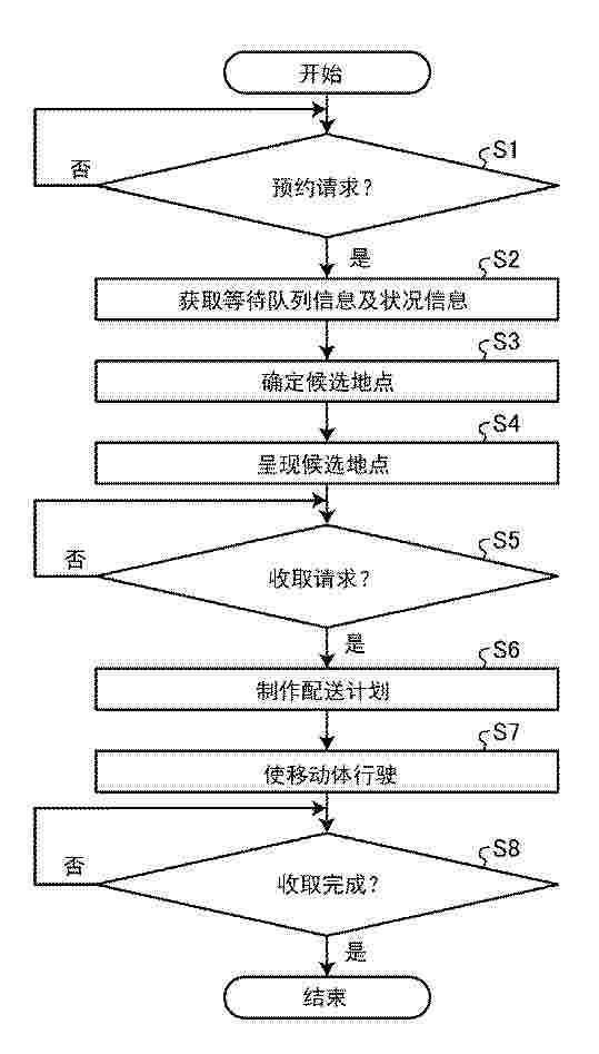
A product delivery method according to the present disclosure includes acquiring waiting line information. The waiting line information is information about a waiting line. The waiting line includes a user. The product delivery method includes acquiring situation information. The situation information is information about the situation of the user. The product delivery method includes identifying, on the basis of the waiting line information and the situation information, one or more candidate locations where a product can be picked up in the waiting line. The product delivery method includes creating a delivery plan for delivering a product to a pickup location in response to a pickup request. The pickup request specifies, as the pickup location, a candidate location selected from among one or more candidate locations through the user's terminal. The product delivery method includes causing a mobile body carrying the product to travel in accordance with the delivery plan.
Resumen de: WO2025136216A1
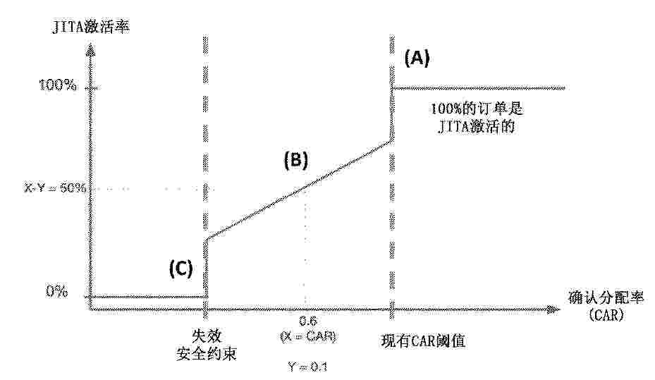
Aspects concern a server for facilitating processing a plurality of orders for an on- demand service, the server comprising: a memory configured to store instructions; a communication interface configured to receive the plurality of orders for the on-demand service from a plurality of computing devices; and a processor for executing the stored instructions and configured to: obtain a first indicator relating to an allocation rate for orders geographically relevant to the plurality of orders and received within a certain time slot; obtain a second indicator for each order of the plurality of orders, the second indicator relates to a likelihood that each order will get allocated to a delivery service provider; select at least one order from the plurality of orders based on the first indicator and the second indicator; and delaying allocating the selected order to the delivery service provider for a predetermined time.
Resumen de: WO2025131610A1
Disclosed is a computer-implemented method of determining, for a berthed vessel at a terminal comprising a plurality of cranes disposed along a crane conveyance system, a proposed allocation of the plurality of cranes to the berthed vessel to perform a plurality of vessel operations on the vessel within a time window. The determining is based at least in part on first data indicative of a status of the berthed vessel at the terminal within the time window, second data indicative of cargo associated with the plurality of vessel operations to be performed within the time window, third data indicative of a number of the plurality of cranes required to perform the plurality of vessel operations within the time window on the berthed vessel, fourth data indicative of a status of the plurality of cranes within the time window, and fifth data indicative of a relative positioning of at least one of the plurality of cranes to the berthed vessel within the time window.
Resumen de: WO2025131611A1
A computer-implemented method of allocating a vessel to a berth at a terminal includes obtaining first data indicative of at least one of a departure time of the vessel from a previously scheduled terminal and an arrival time of the vessel at a next scheduled terminal. The computer-implemented method includes obtaining second data indicative of a fuel operation of the vessel associated with a possible allocation of the vessel to the berth. The computer-implemented method includes determining, based at least in part on the first and second data, a proposed allocation of the vessel to the berth.
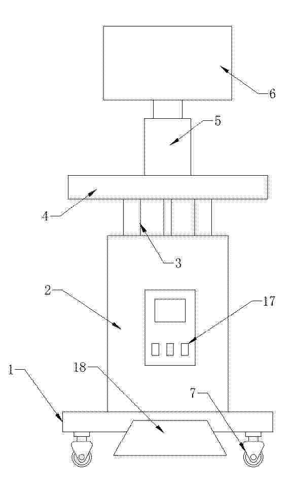
Resumen de: CN120089338A
The invention discloses an AI doctor auxiliary management device and system based on a large model.The AI doctor auxiliary management device comprises a fixed base, a lifting machine shell is fixedly installed at the top end of the fixed base, and a lifting assembly is installed in the lifting machine shell. Rapid medical records, prescription filling and intelligent intervention of auxiliary diagnosis and treatment are provided, so that the diagnosis time of doctors is greatly shortened, and the diagnosis and treatment efficiency of clinics is improved; the pharmacy management function is perfected, the warehouse-in and warehouse-out management function, the inventory checking function, the medicine price adjustment function and the supplier management pharmacy management function are newly added, and the medicine inventory is better managed; perfect financial management is achieved, the functions of charging, refund, arrearage and financial query are provided, and clinic managers are helped to conveniently and rapidly grasp clinic financial conditions; a service platform for clinic transformation is customized by using WeChat, and meanwhile, a membership service function is opened, so that the platform popularization capability of a clinic is improved on the basis of original WeChat popularization.
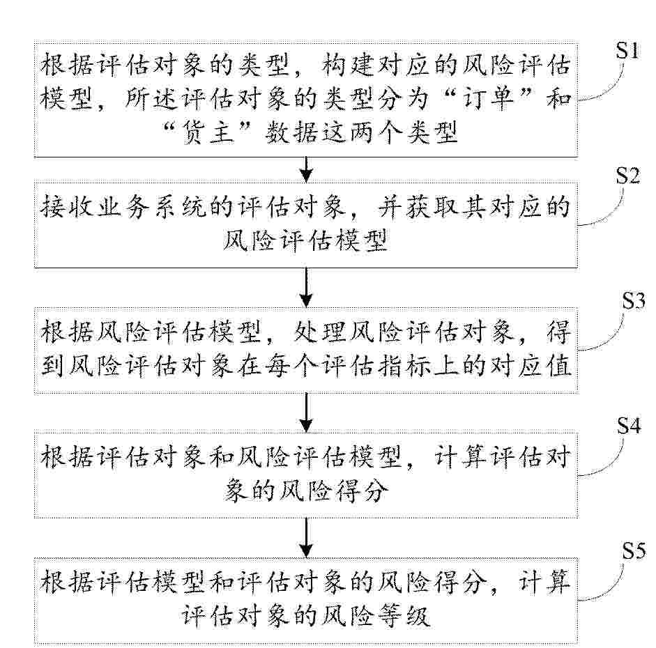
Resumen de: CN122453179A
本发明公开了一种网络货运数字化风险管理方法及系统、电子设备,包括:根据评估对象的类型,构建对应的风险评估模型,所述评估对象的类型分为“订单”和“货主”数据这两个类型;接收业务系统的评估对象;分析所述评估对象,计算出评估对象对应指标维度上的指标数值;根据所述指标数值,分析所述指标数值对应的评估对象的类型;根据所述评估对象的类型,获取对应的风险评估模型;根据评估对象的指标数值与评估对象的风险评估模型,计算评估对象的风险等级。实现对网络货运中“订单”和“货主”风险评估策略的快速调整,提升风险评估的效率及准确度,降低风险评估的成本。
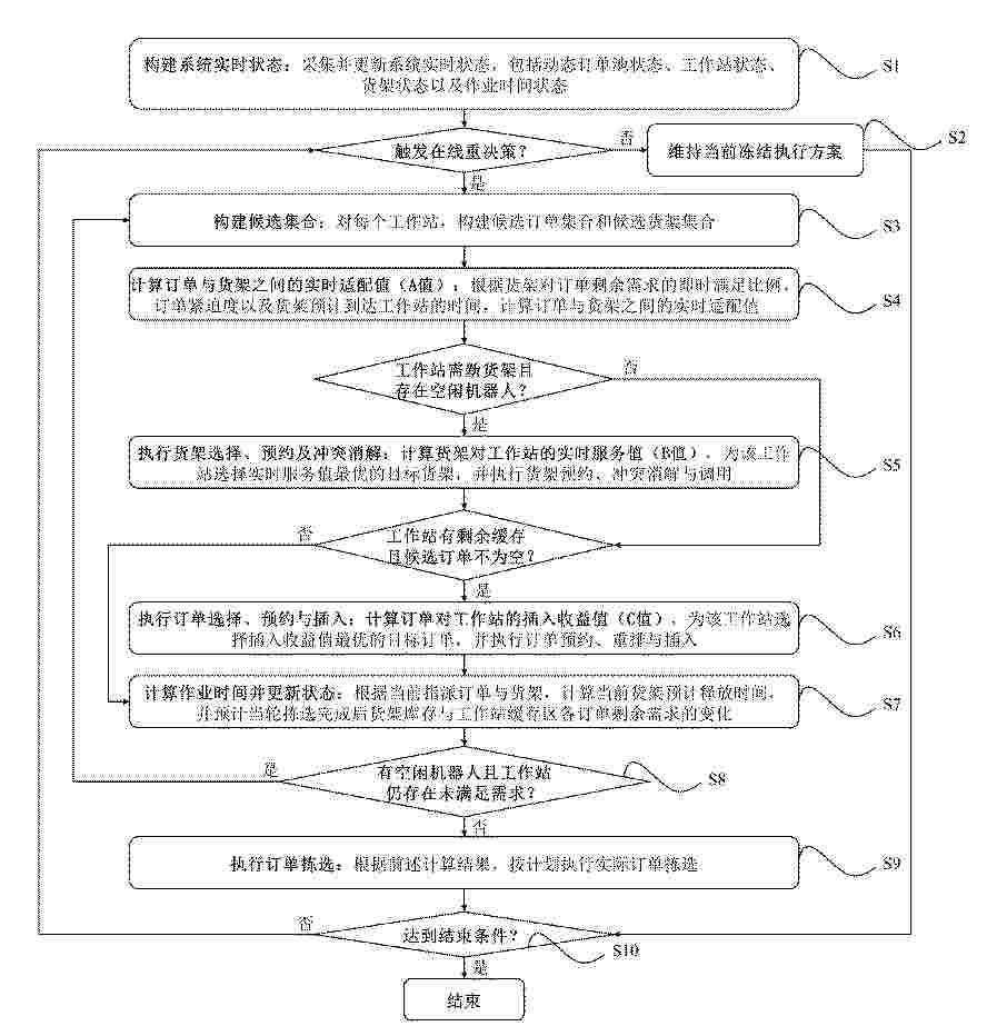
Resumen de: CN122453331A
本发明公开了一种机器人移动货架系统订单与货架在线协同选择及排序方法,属于智能仓储技术领域。所述方法面向订单持续到达和货架动态调用的在线运行场景,在订单到达、订单完成、货架释放或达到滚动决策时点时触发在线重决策;对各工作站构建候选订单集合和候选货架集合;根据货架对订单剩余需求的满足比例、订单紧迫度、货架预计到站时间及工作站负载情况,动态评估订单与货架的实时适配值、货架对工作站的实时服务值和订单对工作站的插入收益值;据此实时选择目标货架并执行冲突消解与调用,选择目标订单并执行订单重排与插入;根据实时拣选进度更新系统状态。本方法可减少货架搬运次数,缩短订单响应时间,提高多工作站协同拣选效率。
Resumen de: CN122452150A
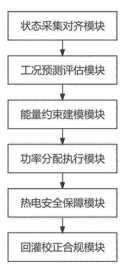
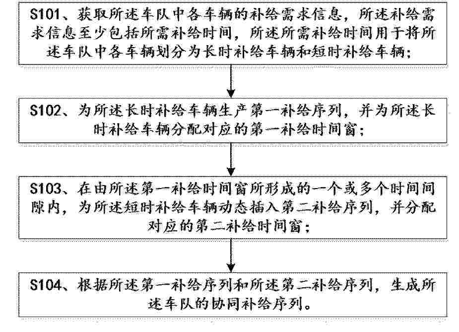
本发明公开了一种新能源汽车分布式能量协同管理系统及方法,涉及新能源汽车管理技术领域,采集车队对齐状态数据集进行预测,依据预测结果与补能节点可用功率构建车队整体功率分配与补能约束模型,生成牵引功率分配策略、再生吸收策略与补能指令,本发明通过多源数据融合与闭环反馈,实现车队级能量统一调度和路段级预测驱动,构建协同能量约束模型,采用分布式最优功率分配与热负荷滞后补偿机制,实现牵引、再生和冷却的动态平衡,通过回灌校正与补能优先级自适应调整,可持续优化能量分配策略,显著提升车队能效、热安全性与受限路段通行稳定性,适用于在封闭和受控道路环境下运行的新能源汽车车队。
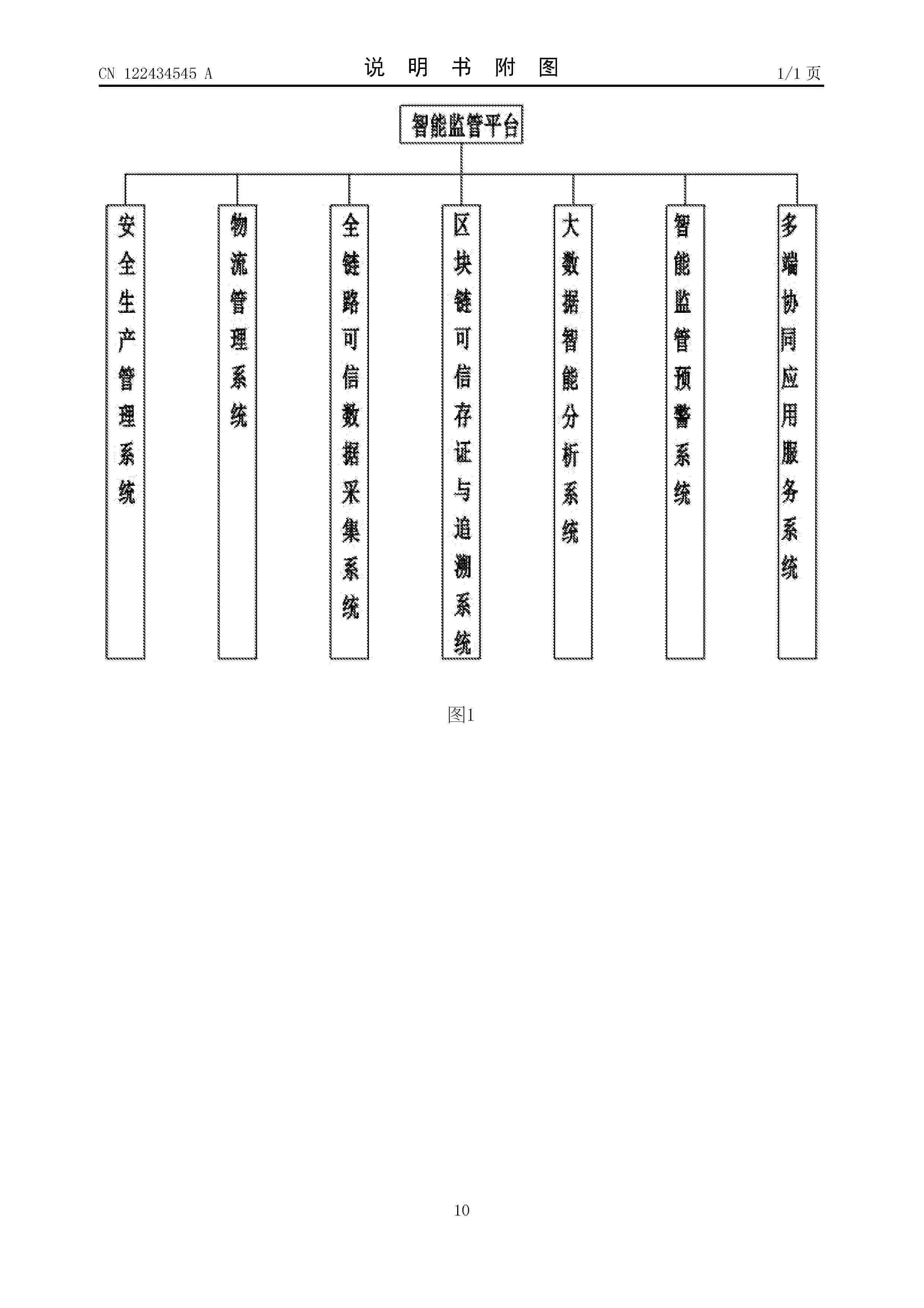
Resumen de: CN122453545A
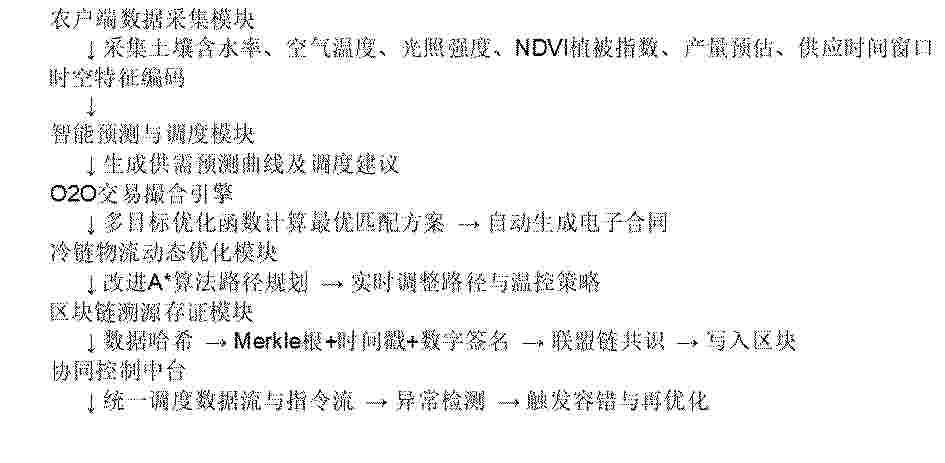
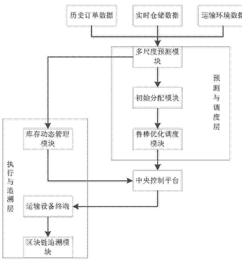
本发明公开了农业产业O2O智能供应链协同管理平台及其构建方法,平台包括农户端数据采集模块、智能预测与调度模块、O2O交易撮合引擎、冷链物流动态优化模块、区块链溯源存证模块及协同控制中台。构建方法包括:采集多维农业数据并进行时空特征编码;采用混合深度学习与自适应优化算法生成产销匹配策略;结合冷链运输能耗模型与路径实时调整机制实现物流最优化;利用区块链不可篡改特性记录全链路数据,实现农产品溯源与交易可信保障。本发明可有效提高农业供应链的响应速度、降低损耗率、提升交易透明度,适用于多种农业产业模式。
Resumen de: CN122443908A
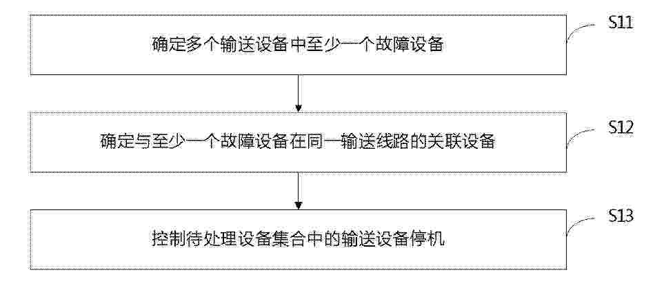
本公开涉及一种控制方法、装置、存储介质和程序产品,涉及控制技术领域。该控制方法,包括:确定多个输送设备中至少一个故障设备;根据多个输送设备之间的关联信息,确定与至少一个故障设备在同一输送线路的关联设备,以创建待处理设备集合,待处理设备集合包括与至少一个故障设备处于不同的通信通道的输送设备;控制待处理设备集合中的输送设备停机。本公开的技术方案能够降低停机指令下发过程中的响应延迟,从而提高对输送设备的控制效果。
Resumen de: CN122457386A
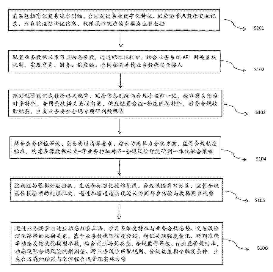
本发明提供了一种基于多模态融合的智能数据安全态势感知与管理方法及装置,应用于数据处理领域。本申请通过采集商业交易、合同、供应链、财务及权限操作多模态业务数据,配置采集节点参数并依托标准化接口与API网关鉴权实现异构数据安全接入;经格式规整、冗余剔除与归一化预处理,提取多维度业务特征并生成专项研判数据集;结合业务价值、实时性、算力分配与合规标准构建一体化融合策略,按场景完成数据集批次拆分与加密边云传输;采用自适应动态权重算法学习特征映射关系,优化模型参数并动态适配研判规则,最终输出合规感知结果与全流程管理方案。
Resumen de: CN122452841A
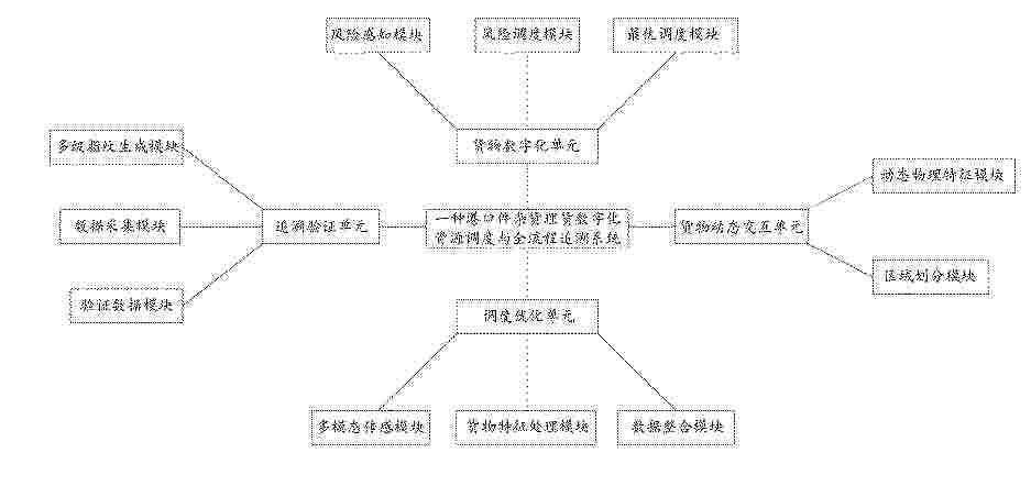
本发明涉及货物调度技术领域,具体为一种港口件杂货理货数字化资源调度与全流程追溯系统,包括货物数字化单元、货物动态交互单元、调度优化单元以及追溯验证单元。本发明以货物与环境的物理交互特征为核心驱动要素,通过多模态传感器进行大数据采集实时捕捉货物状态与环境扰动,实现从静态属性到动态行为的全维度数字化映射,这种物理特征闭环驱动机制不仅提升了调度决策的精准度,更通过不可逆的环境扰动指纹技术,构建了具备混沌特性的追溯体系,有效解决了传统追溯系统易篡改、难复现的问题;其次,创新性地设计三级风险感知调度体系,将风险评估与资源调度深度耦合,这种分层响应策略既保障了作业安全,又避免了资源浪费。
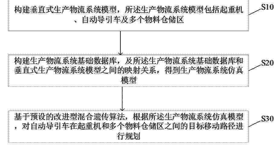
Resumen de: CN122453296A
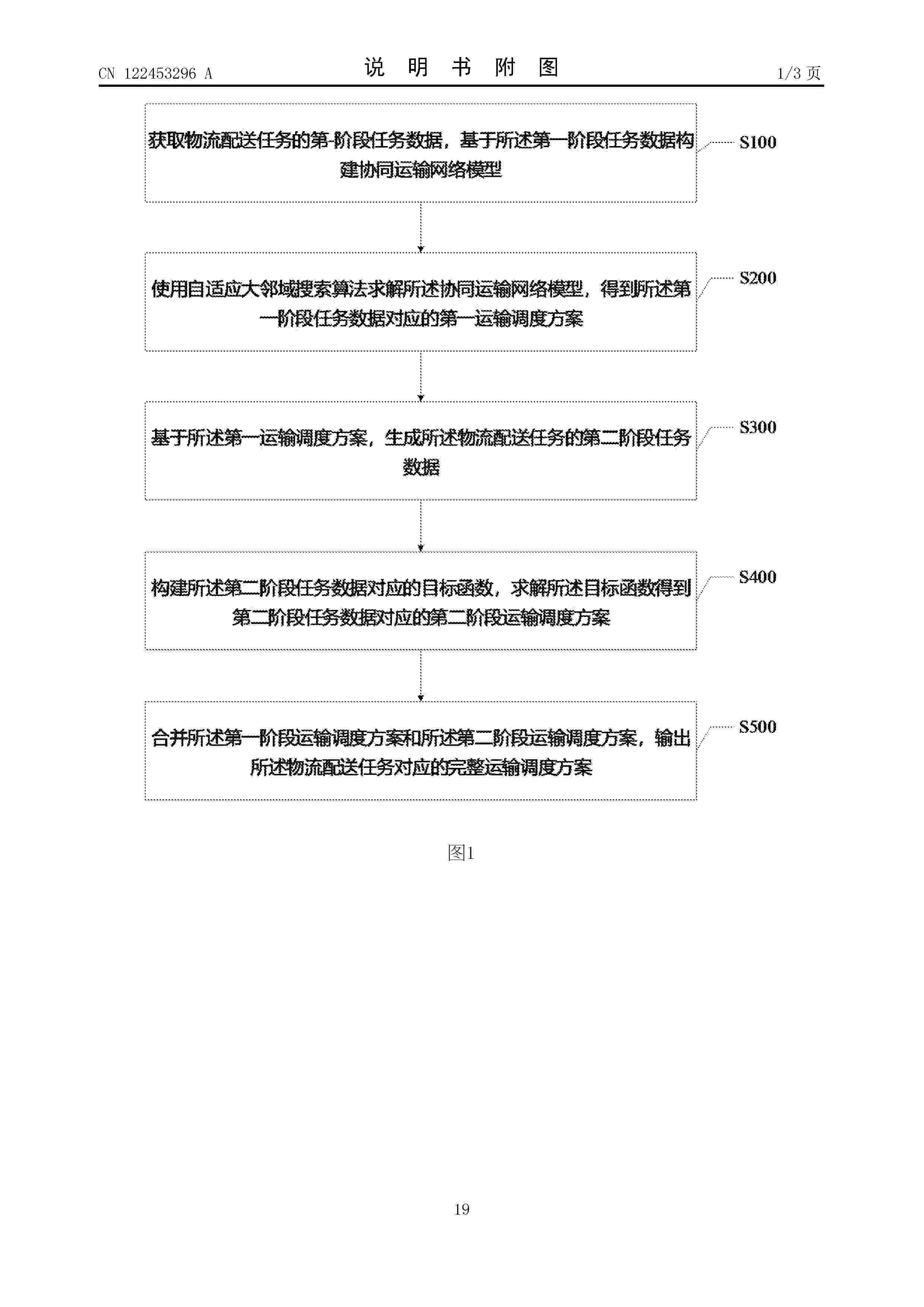
本发明涉及智慧物流技术领域,公开了一种基于多载具协同的运输调度方法、系统、终端及存储介质,包括:获取物流配送任务的第一阶段任务数据,基于第一阶段任务数据构建协同运输网络模型;使用自适应大邻域搜索算法求解协同运输网络模型,得到第一阶段任务数据对应的第一运输调度方案;基于第一运输调度方案,生成物流配送任务的第二阶段任务数据;构建第二阶段任务数据对应的目标函数,求解目标函数得到第二阶段任务数据对应的第二阶段运输调度方案;合并第一阶段运输调度方案和第二阶段运输调度方案,输出物流配送任务对应的完整运输调度方案。本发明能够解决运输调度方案多阶段转运的时空同步问题,并提高末端配送的灵活性。
Resumen de: CN122453430A
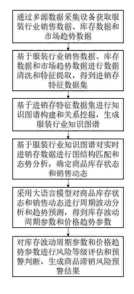
本发明涉及服装进销存管理技术领域,公开了基于大数据分析的进销存智能管理系统及方法。该方法包括通过多源设备采集销售、库存及市场趋势数据,经清洗与特征提取形成进销存特征数据集;基于数据集构建知识图谱并挖掘关系,生成含商品属性、销售关联及市场趋势演化网络的行业知识图谱;依托知识图谱对实时进销存数据做图结构匹配与态势分析,明确商品库存状态及销售动态;采用大语言模型对上述状态与动态进行周期波动分析及趋势预测,得到库存波动周期与价格趋势参数;评估参数风险等级并判断预警,生成商品滞销风险预警结果,助力提升服装企业进销存管理智能化程度。
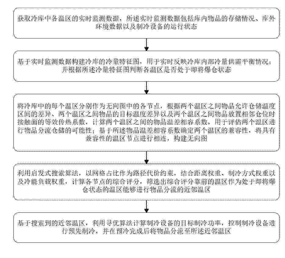
Resumen de: CN122453320A
本申请涉及温度控制技术领域,具体涉及基于多温区实时监控的冷链仓储温度调控方法及系统,该方法包括:获取冷库中各温区的实时监测数据;构建冷库的冷量特征图,并根据所述冷量特征图判断各温区是否处于即将爆仓状态;计算两个温区之间的物品温差相容系数,以确定两个温区的兼容性,构建无向图;利用启发式搜索算法,筛选出综合评分靠前的温区作为处于即将爆仓状态的温区能够进行物品分流的近邻温区;基于搜索到的近邻温区,利用寻优算法计算制冷设备的目标制冷功率,控制制冷设备进行预先制冷,并在预冷完成后将物品分流至所述近邻温区。本申请旨在避免爆仓发生后的滞后响应问题,提高物品分流的效率。
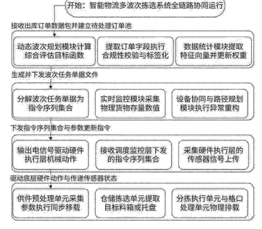
Resumen de: CN122453318A
本发明涉及自动化分拣技术领域,公开了一种智能物流多候选波次拣选系统及方法,系统设业务管理层、调度监控层、电控控制层和硬件执行层,业务管理层对订单合规校验与标签化,结合时效、空间及设备负载计算目标函数生成候选波次任务,调度监控层将任务分解为指令序列,并执行调节与路由重构。硬件执行层完成物料提取、输送、预处理及分拣,系统比对缓存区存量与阈值以调节作业节奏;供件环节基于特征向量执行比对与速度同步移载,故障时,重构节点拓扑图矩阵执行路径规划;满载时,利用备用映射表执行地址覆写,系统基于执行数据计算损失函数的偏导数,实现权重参数的自学习更新。本发明实现了全链路精准协同与动态容错,提升了作业效率与稳定性。
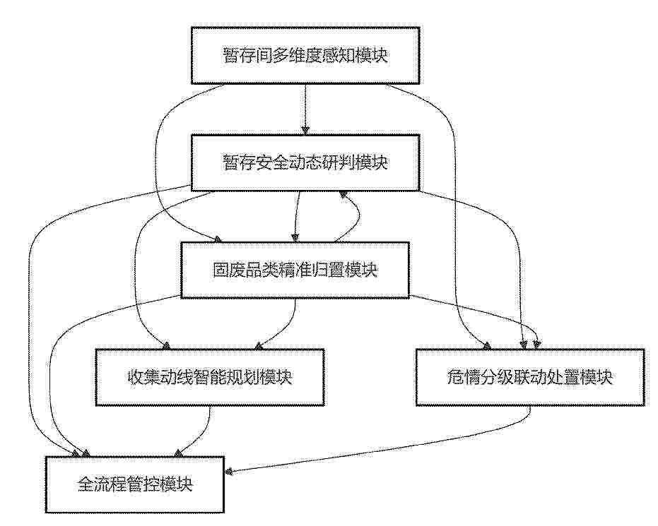
Resumen de: CN122452906A
本发明属于固体危废物管理技术领域,具体是基于危废暂存间的固体危废物暂存收集管理方法及系统,具体包括暂存间多维度感知模块、暂存安全动态研判模块、固废品类精准归置模块、收集动线智能规划模块、危情分级联动处置模块和全流程管控模块;本发明是通过动态核算安全容量并判定超容风险,按相容性标准实现危废精准归置并排查混放隐患,保障暂存合规性,且结合多目标优化生成最优路径与标准化指令,提升收运效率并降低作业风险,以及整合多维度风险数据,量化判定各贮存点与整体危情等级,触发差异化处置指令以避免处置不当,实现固体危废物从入库到转运的智能化和精细化管控,有效的降低危废暂存过程中的环境风险与安全事故发生率。
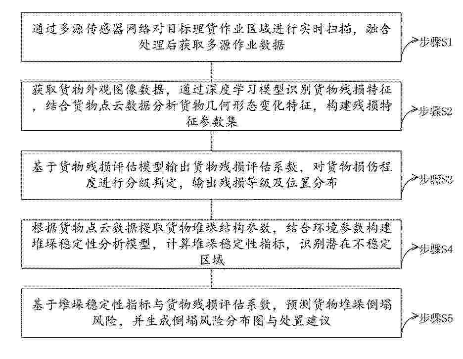
Resumen de: CN122453126A
本发明涉及港口数据分析技术领域,具体公开了一种港口智慧理货车的控制方法、系统及装置,本发明通过多源传感器网络获取多源作业数据,通过深度学习模型识别货物残损特征,结合货物点云数据分析货物几何形态变化特征,构建残损特征参数集,基于货物残损评估模型输出货物残损评估系数,对货物损伤程度进行分级判定,输出残损等级及位置分布,根据货物点云数据提取货物堆垛结构参数,结合环境参数构建堆垛稳定性分析模型,计算堆垛稳定性指标,识别潜在不稳定区域,基于堆垛稳定性指标与货物残损评估系数,预测货物堆垛倒塌风险,并生成倒塌风险分布图与处置建议,本发明实现了理货作业的智能化、可视化与精细化管理。
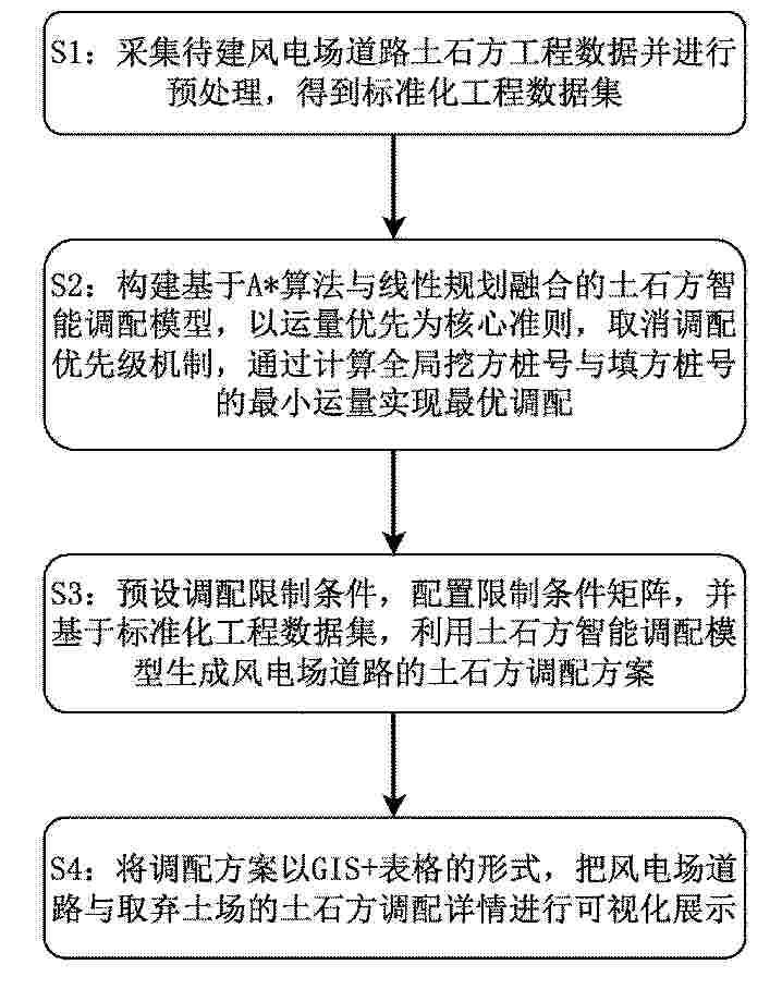
Resumen de: CN122453281A
本发明涉及风力发电场建设技术领域,尤其涉及一种风电场道路施工土石方智能调配方法、系统及设备。调配方法包括:采集待建风电场道路土石方工程数据并进行预处理,得到标准化工程数据集;构建基于A*算法与线性规划融合的土石方智能调配模型,所述模型以运量优先为核心准则,取消调配优先级机制,通过计算全局挖方桩号与填方桩号的最小运量实现最优调配;预设调配限制条件,配置限制条件矩阵,并基于标准化工程数据集,利用土石方智能调配模型生成风电场道路的土石方调配方案。本发明适配风电场道路拓扑特性,通过全局运量优先实现了风电场道路土石方的高效合理调配,有效控制了施工成本。
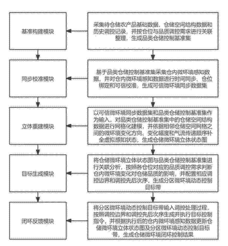
Resumen de: CN122450237A
本发明公开了基于多源大数据的仓储微环境自动控制系统,涉及自动控制技术领域,包括,立体重建模块,以可信微环境同步数据集和品类仓储控制基准集作为输入,对品类仓储控制基准集中的仓储空间结构数据进行网格化建模,并依据相邻仓储空间网格之间的微环境变化方向、变化幅度和气流传递顺序补全虚拟感知状态,生成仓储微环境立体状态图;目标生成模块,将仓储微环境立体状态图与品类仓储控制基准集进行关联分析,按照各仓位对应的品质调控需求判断仓内微环境变化对仓储品质的影响,并配置相应调控边界和调控先后次序,生成分区微环境动态控制目标带。本发明能够提高仓储微环境状态表达的完整性和分区调控依据的准确性。
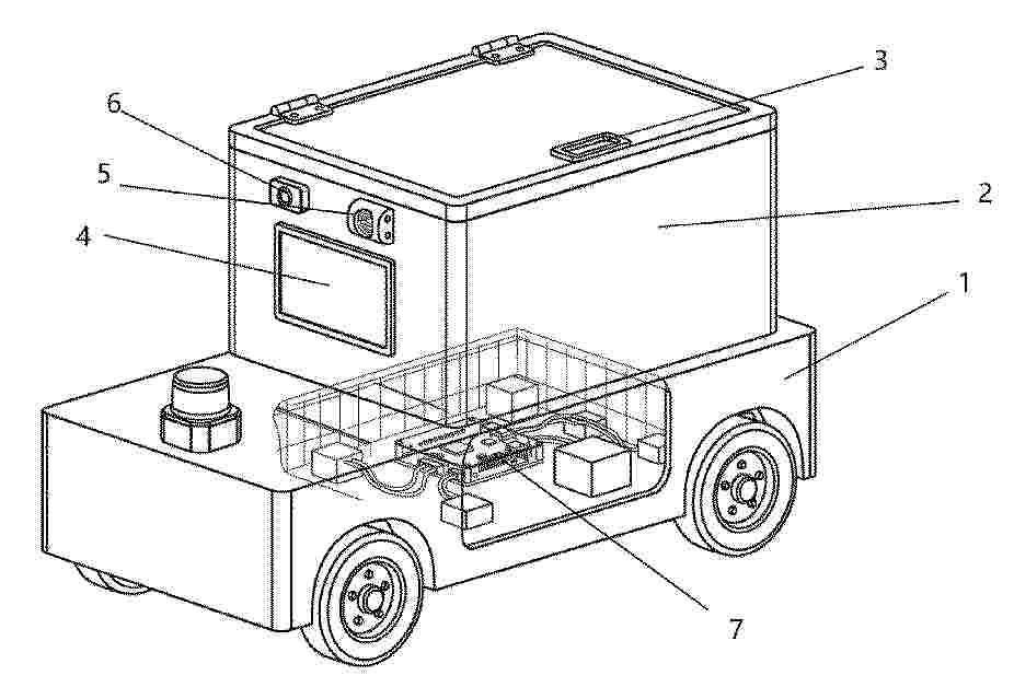
Resumen de: CN122453287A
本发明公开了一种行李配送机器人及其控制方法,属于机器人技术领域。所述机器人包括移动模块、行李放置模块、锁控模块、视觉采集模块及中央处理模块等。中央处理模块涵盖异步消息通信框架及视觉解析、配送顺序规划、导航等多个单元。所述控制方法通过视觉解析单元解码二维码快速创建任务;在配送规划阶段,通过提取多维度任务特征构建特征矩阵,并融合主成分分析降维与神经网络模型进行综合优先级评分,以生成最优任务执行序列;最后通过导航单元依次行驶,并在到站后自动解锁舱门。本发明简化了任务触发流程,显著提升了多任务场景下配送顺序规划的智能化程度与整体效率,并有效降低了交付环节的人工参与度。
Resumen de: CN122453027A
本发明属于物料配送技术领域,且公开了一种AMR线边物料配送协同管理系统,采用激光SLAM无轨自主导航与视觉‑激光亚像素级融合定位技术,系统可基于激光雷达实时采集车间环境点云数据自主构建并动态更新地图,产线布局调整、工位迁移时无需停产改造,缩短了产线换型周期;视觉‑激光融合定位可有效抵消车间粉尘、光线变化、设备移动等环境干扰,实现复杂场景下毫米级精准定位,配合地图分区管理功能,按物料类型、工位区域划分导航权限,进一步提升配送秩序与安全性;搭建跨系统深度协同与全流程数据闭环管理体系,系统通过标准化API接口与OPCUA工业通信协议,实现与核心生产仓储系统的加密对接与数据实时互通。
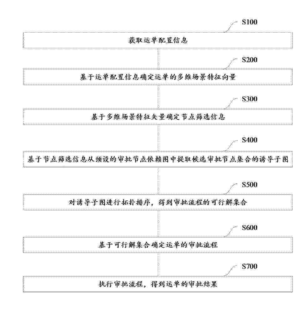
Resumen de: CN122453362A
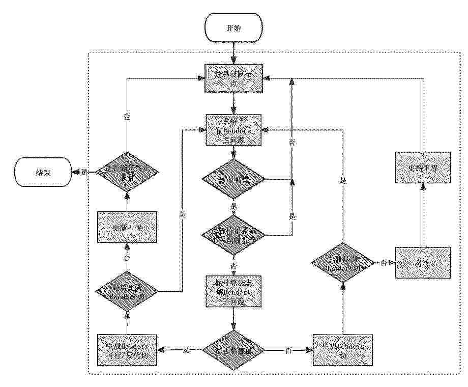
本申请公开了一种基于运单多维特征的智能审批方法、系统、电子设备及存储介质,该方法包括获取运单配置信息;基于运单配置信息确定运单的多维场景特征向量;基于多维场景特征向量确定运单的场景类型;基于多维场景特征向量和历史运单数据确定运单的场景稀有度;基于场景稀有度确定节点筛选阈值;基于场景类型和节点筛选阈值确定节点筛选信息;基于节点筛选信息从预设的审批节点依赖图中提取候选审批节点集合的诱导子图;对诱导子图进行拓扑排序,得到审批流程的可行解集合;基于可行解集合确定运单的审批流程;执行审批流程,得到运单的审批结果。本申请通过基于多维场景特征向量确定节点筛选信息,审批流程能够自适应地匹配运单的多维特征。
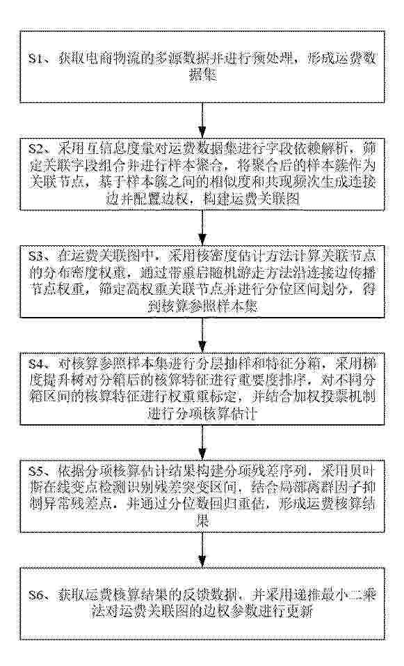
Resumen de: CN122453304A
本发明公开了一种基于大数据分析的电商物流运费智能核算系统及方法,包括如下步骤:S1、获取多源数据并进行预处理;S2、进行字段依赖解析,筛定关联字段组合并进行样本聚合,构建运费关联图;S3、计算关联节点的分布密度权重,沿连接边传播节点权重,筛定高权重关联节点并进行分位区间划分;S4、进行分层抽样和特征分箱,进行重要度排序,对不同分箱区间的核算特征进行权重重标定,并进行分项核算估计;S5、识别残差突变区间,抑制异常残差点并通过分位数回归重估,形成运费核算结果;S6、获取反馈数据,并对边权参数进行更新。本发明能够实现电商物流运费的关联化建模,提升运费核算准确性和异常费用识别能力。
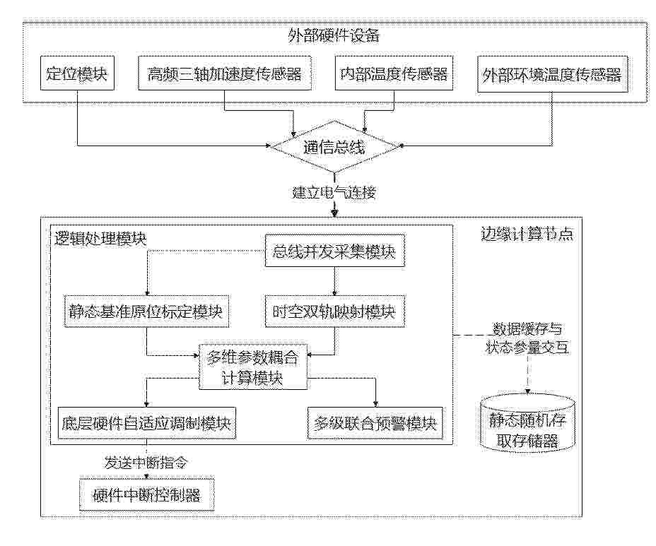
Resumen de: CN122453299A
本申请涉及物流监测与数据分析技术领域,公开了一种基于大数据分析的物流异常预警方法及系统,方法包括:接收多传感器输出的底层异构数据流;基于车辆运动学约束条件进行状态判定,在满足静态基准条件时提取温度差值,计算并更新热力学归一化参数;对振动数据进行时间域特征提取并结合运动位移进行空间域对齐聚合,生成空间切片特征数据;结合热力学归一化参数计算频域与空间梯度耦合劣化风险指数;计算劣化加速梯度,达到触发设定值时发送中断指令,调整通信总线时钟频率与物理采样率并重置步进长度参数;基于滑动窗口对风险指数进行累加积分计算,达到预警阈值时输出异常追溯数据包。本发明实现了数据的有效空间对齐,兼顾了功耗与监测精度。
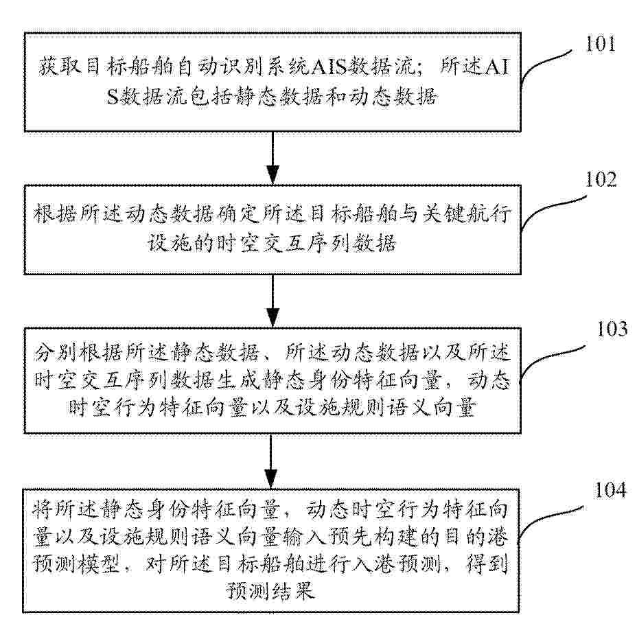
Resumen de: CN122453291A
本发明公开了一种船舶目的港行为预测方法及装置,该方法包括:获取目标船舶自动识别系统AIS数据流;AIS数据流包括静态数据和动态数据;根据动态数据确定目标船舶与关键航行设施的时空交互序列数据;分别根据静态数据、动态数据以及时空交互序列数据生成目标船舶的静态身份特征向量,动态时空行为特征向量以及设施规则语义向量;将静态身份特征向量,动态时空行为特征向量以及设施规则语义向量输入预先构建的目的港预测模型,对目标船舶进行入港预测,得到预测结果。利用本发明方案,可以实现端到端的预测,而且能够得到准确的预测结果。
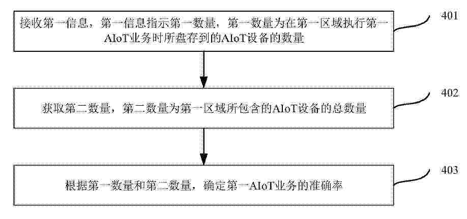
Resumen de: CN122457979A
一种通信方法及装置,用于确定盘存业务的准确率。该方法包括:接收第一信息,第一信息指示第一数量,第一数量为在第一区域执行第一AIoT业务时所盘存到的AIoT设备的数量。根据第一数量和第二数量,确定第一AIoT业务的准确率,第二数量为第一区域所包含的AIoT设备的总数量。可以理解为,本申请实施例提供了一种确定盘存业务的准确率的方式,实现了盘存业务的准确率的确定。盘存业务的准确率的评估可帮助更好的了解盘存业务的实际执行情况,及时发现盘存业务的问题和潜在风险,从而针对盘存业务做出更有针对性的决策。
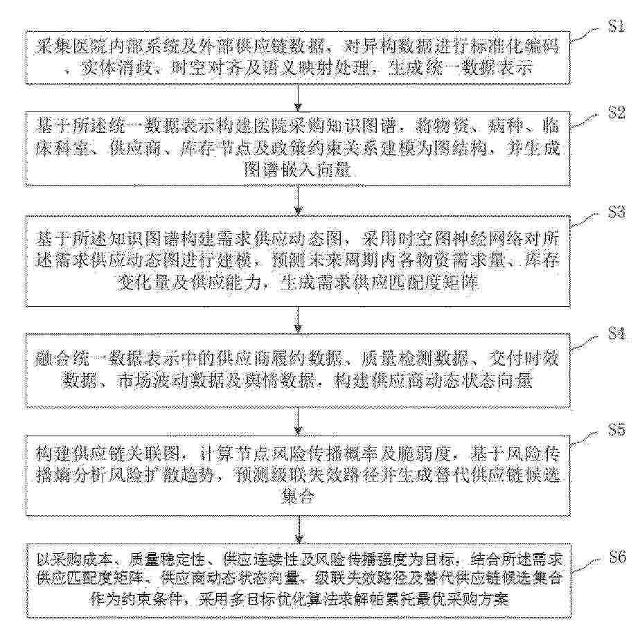
Resumen de: CN122455286A
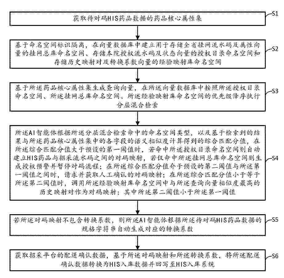
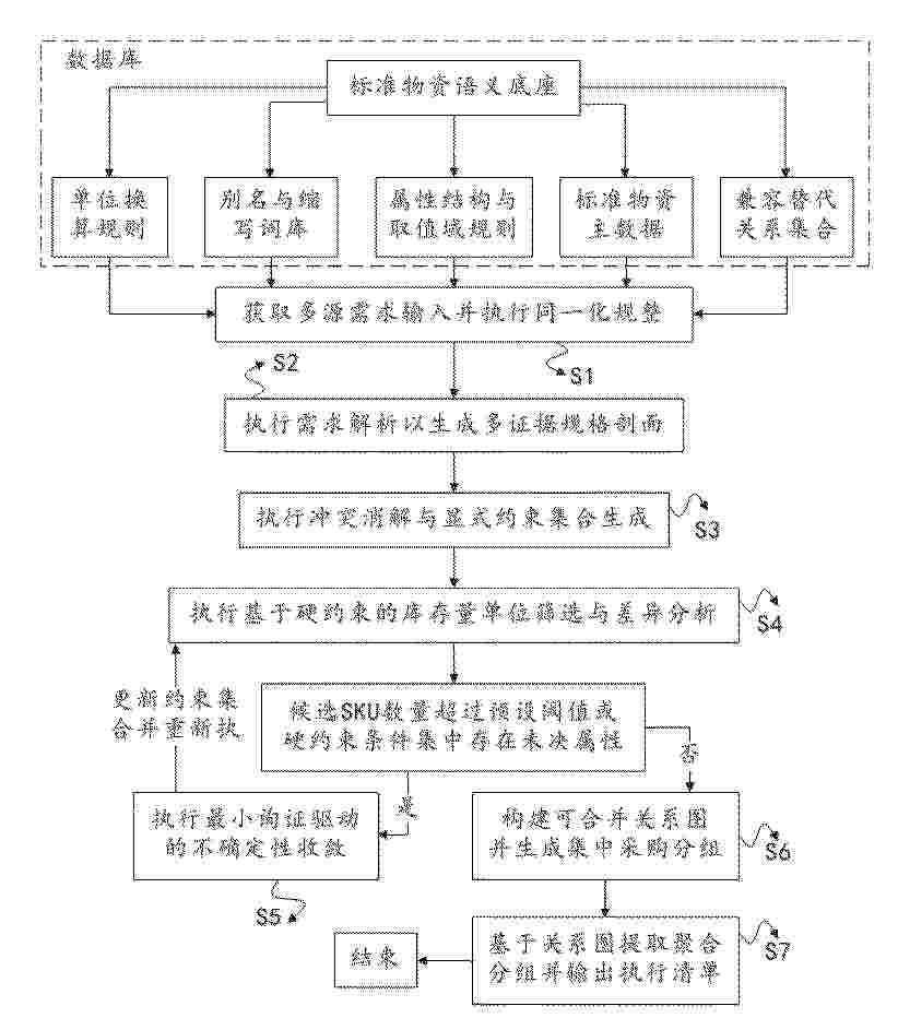
本发明提供了一种医院智慧招采多源融合智能决策方法及系统,涉及医疗物资供应链管理与智能决策技术领域。该方法通过医院内部系统及外部供应的多源异构数据,经标准化编码、实体消歧与时空对齐生成统一数据表示;基于知识图谱构建物资、病种、供应商及政策约束的关联模型,并利用时空图神经网络预测需求与供应变化,形成需求供应匹配度矩阵;结合多模态特征融合构建供应商动态状态向量,并通过供应链风险传播分析预测级联失效路径;在此基础上采用多目标优化算法求解帕累托最优采购方案;并通过执行反馈实现模型在线更新与闭环优化。本发明提高了采购预测精度与供应链风险控制能力。
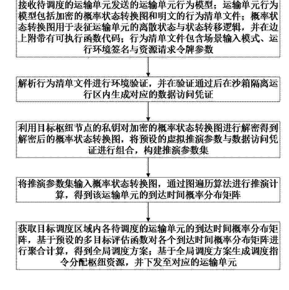
Resumen de: CN122453295A
本发明属于物流调度与供应链管理的技术领域,涉及了一种跨模态运输时空节拍协同调度方法及系统,包括:接收待调度运输单元的行为模型,其含加密的概率状态转换图与明文行为清单文件;解析清单文件进行环境验证,在沙箱隔离区内生成数据访问凭证;利用枢纽节点私钥对加密转换图进行解密,并将虚拟推演参数与凭证组合构建推演参数集;将参数集输入转换图,通过图遍历算法推演得到该单元的到达时间概率分布矩阵;获取区域内各单元的概率分布矩阵,基于多目标评估函数聚合计算得到全局调度方案,并据此生成下发分配资源的调度指令。本发明解决了如何在保障各运输主体数据安全的同时,实现跨模态运输资源深度协同与动态调度的问题。
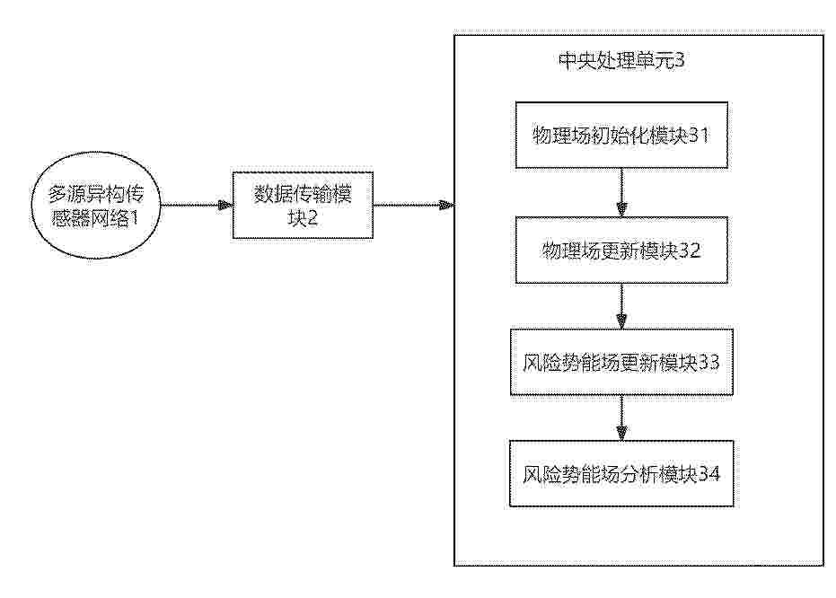
Resumen de: CN122453178A
本发明公开一种仓储环境风险实时监测与智能防控系统,涉及仓储安全技术领域,包括部署在仓储区域内的多源异构传感器网络、数据传输模块和中央处理单元;多源异构传感器网络与中央处理单元通过数据传输模块实现数据交互;所述中央处理单元通过归一化通用势传导插值算法生成所有物理场的初始连续分布。本发明通过归一化通用势传导插值算法,融合空间各向异性与多物理场耦合效应,将离散传感器数据精准重建为全空间连续物理场,消除了监测盲区;基于物理场量化风险演化,实现早期隐患识别与分级智能防控,显著提升仓储环境风险监测的准确性与防控的及时性。
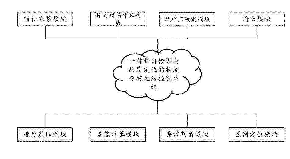
Resumen de: CN122453324A
本发明公开了一种带自检测与故障定位的物流分拣主线控制系统,属于物流分拣自动化控制技术领域。速度获取模块采集各分拣工位的实时分拣速度,差值计算模块生成相邻工位的速度差序列;异常判断模块检测速度差序列将对应工位区间标记为疑似故障区间;特征采集模块读取分拣产品的标识及通过各工位的时间戳,时间间隔计算模块追踪同一产品并计算相邻工位间的实际时间间隔,故障点确定模块将实际时间间隔与标准时间间隔进行比较,将偏差起始工位确定为故障点;输出模块将故障点位置信息发送至监控终端。本发明通过速度差传导分析与产品通过时间特征追踪相结合,实现了分拣主线上故障区间的自动定位与故障点的精确识别。
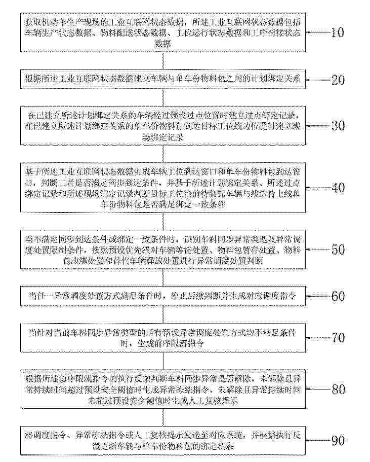
Resumen de: CN122453100A
本发明公开了一种工业互联网机动车生产协同调度方法及系统,方法包括获取车辆生产、物料配送、工位运行和工序衔接状态数据,建立车辆与单车份物料包的计划绑定关系,并在车辆过点和物料包到达线边时分别建立过点绑定记录和现场绑定记录;基于车辆工位到达窗口和单车份物料包到达窗口判断同步到达条件,并结合计划绑定关系、过点绑定记录和现场绑定记录判断绑定一致条件;当出现车料同步异常时,依次进行车辆等待处置、物料包暂存处置、物料包改绑处置和替代车辆释放处置判断,不能完成调度处置时生成前序限流指令,并依据执行反馈生成异常冻结指令或人工复核提示,更新绑定状态。该方法可降低车料错配和局部异常扩散风险。
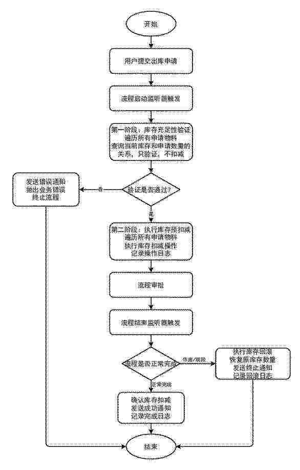
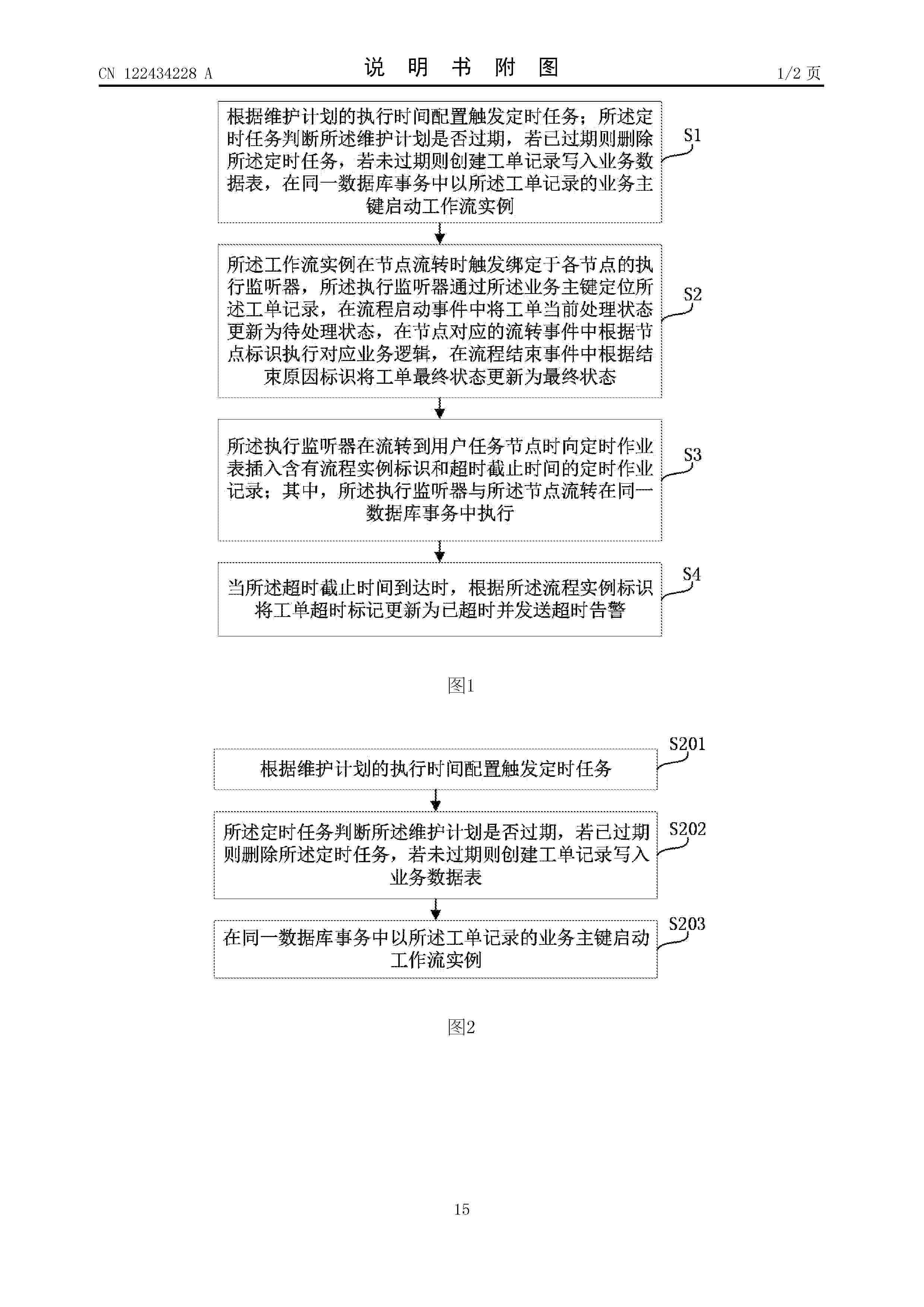
Resumen de: CN122453312A
本发明公开了一种基于时间序列预测的灌区智能库存管理系统及方法。系统包括库存管理子系统和预测预警子系统。库存管理子系统采用工作流引擎实现物料出入库的事务性管理,通过流程启动监听器执行两阶段库存验证和预扣减,通过流程结束监听器根据审批结果执行库存确认或回滚,保证库存数据一致性。预测预警子系统采用ARIMA时间序列模型预测未来7天的物料需求,根据预测结果和当前库存进行智能预警,提前为采购决策提供依据。本发明解决了传统库存管理被动响应、缺乏事务性保障、未充分利用历史数据的问题,实现了预测性库存管理,提高了库存周转率,降低了缺货风险和库存成本,特别适用于具有季节性特征的灌区物料管理场景。
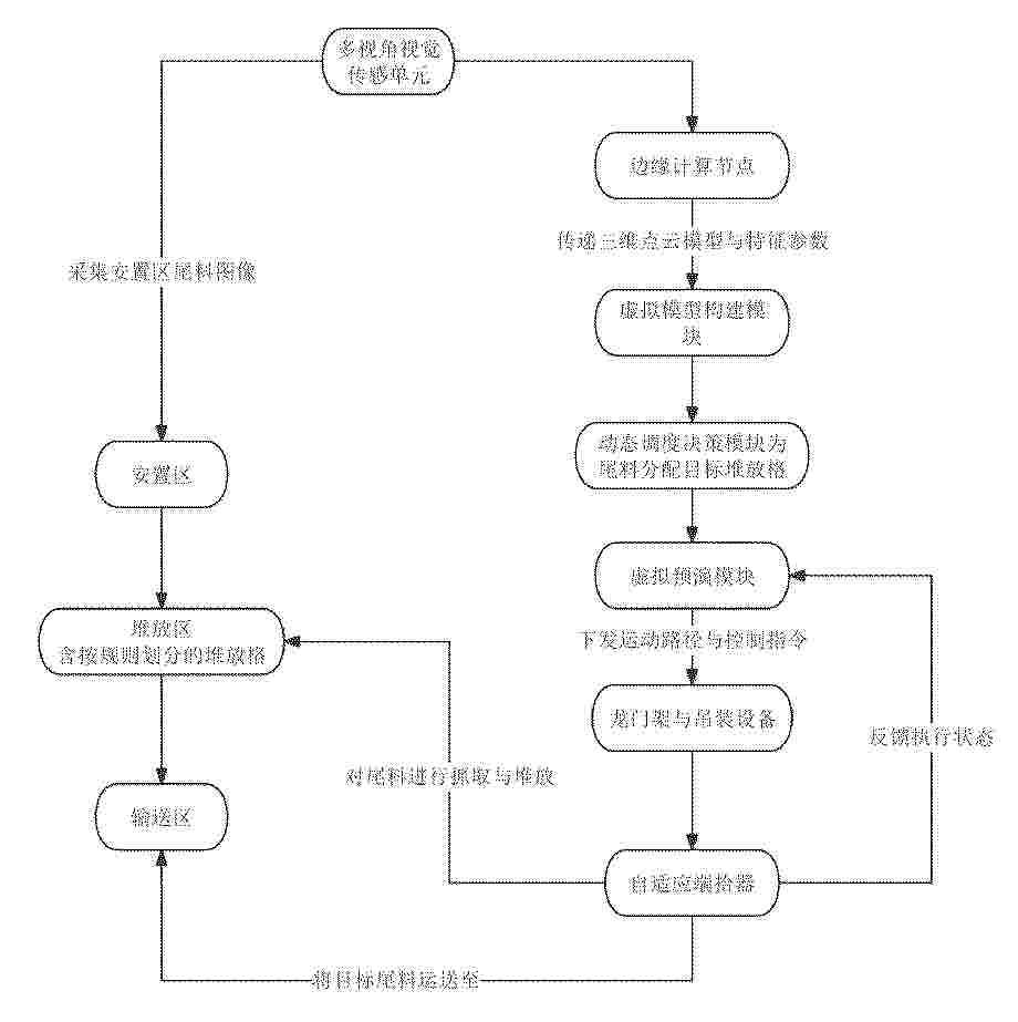
Resumen de: CN122441648A
本发明提供了一种基于视觉引导的板材尾料智能化分级设备及方法,其核心在于通过集成多视角视觉感知、自适应抓取、数字孪生和云边协同控制技术,实现板材尾料从入库、分级存储到按需取用的全流程智能化管理;利用相机阵列采集尾料多视角图像,通过立体匹配算法重建三维点云,提取尾料的形态特征参数;借助数字孪生技术,为每块尾料生成并同步其虚拟模型,基于遗传算法优化堆放策略,最大化空间利用率;当接收到取用请求时,系统可在数字孪生环境中进行虚拟切割预演,精准匹配需求,并通过暂存‑回填机制取用被堆叠的尾料;最终,通过云边协同平台实现对库存、设备状态的可视化监控及全局调度优化,显著提升尾料管理效率和材料利用率。
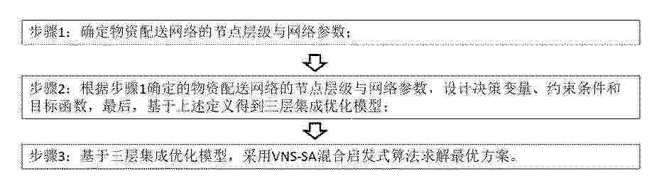
Resumen de: CN122452882A
应急物流枢纽选址、车辆分配与任务调度的集成优化方法,属于应急物流运筹优化技术领域。首先,针对应急物流网络,确定物资配送节点的一级、二级、三级层级划分与基础参数;其次,设计枢纽选址、车辆分配与任务调度三层决策的决策变量、约束条件与目标函数,建立三层集成优化模型;再次,设计一体式编码策略,将三层决策变量统一表征在同一编码结构中;最后,基于三层集成优化模型,采用VNS‑SA混合启发式算法,求解最优的枢纽选址、车辆分配与任务调度方案。本发明适用于大规模突发事件下的应急物资配送场景,在保障物资配送效率的同时,实现运力资源的均衡配置,为应急物流体系提供合理的集成优化方案。
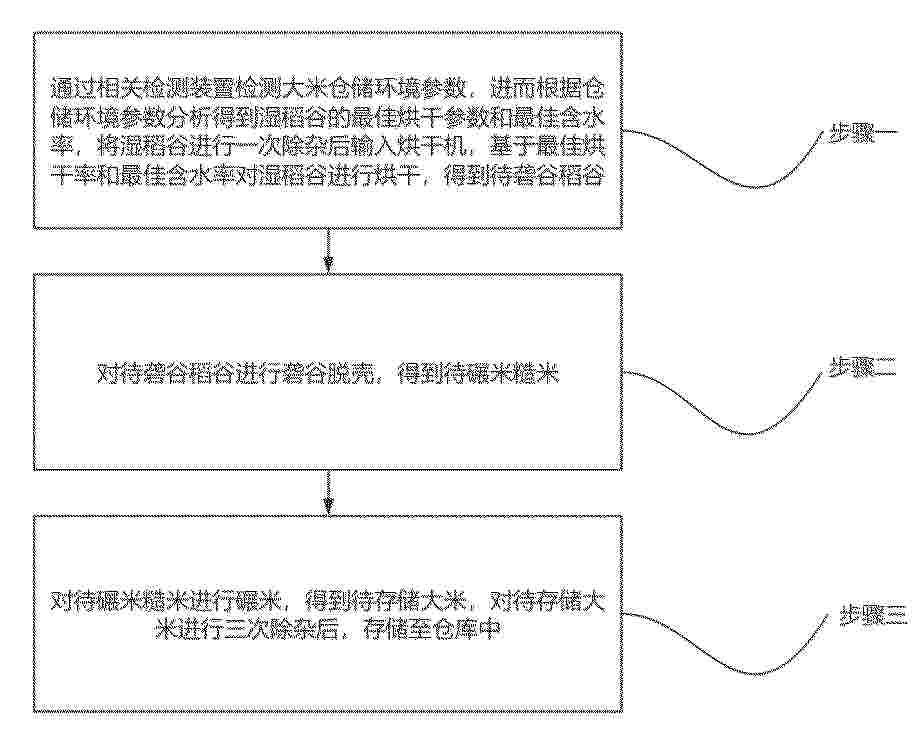
Resumen de: CN122453252A
本发明公开了一种大米加工全流程智能化提质管控方法,涉及大米加工技术领域,本发明通过相关检测装置检测大米仓储环境参数,进而根据仓储环境参数分析得到湿稻谷的最佳烘干参数和最佳含水率,将湿稻谷进行一次除杂后输入烘干机,基于最佳烘干率和最佳含水率对湿稻谷进行烘干,得到待砻谷稻谷;再分析得到最佳砻谷和最佳碾米参数,对砻谷稻谷进行砻谷和碾米。本发明通过大米加工决策模型,以仓储变质率最小为优化目标反向推演输出最优烘干参数与最佳含水率,将仓储霉变风险、虫害风险前置融入烘干管控,既能避免烘干过度造成碎米率上升,又能杜绝烘干不足导致稻谷入库后的变质问题。
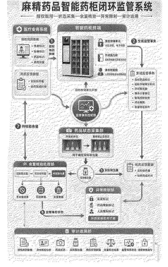
Resumen de: CN122455280A
本发明属于医疗信息化设备管理技术领域,且公开了一种麻精药品智能药柜闭环监管系统,应用于医疗机构对麻醉药品和精神药品的取用流转监管,包括医疗业务数据接口、智能药柜终端、监管事务控制部、药品状态采集部、余量核验处理部、异常限制部和审计追溯部。医疗业务数据接口接收授权用药数据,监管事务控制部生成监管事务并控制目标存储单元开放;药品状态采集部采集开放前后药品状态以确定实际取出量;医疗业务数据接口接收用药反馈数据;余量核验处理部根据实际取出量和实际给药量确定待核验余量,并形成无余量结果、回柜数据或处置数据;监管事务控制部据此更新监管事务状态,异常限制部在异常待处理状态下生成流转限制指令。
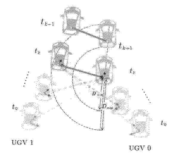
Resumen de: CN122448242A
在双无人地面车辆(UGV)协同运输细长刚体的任务中,生成可执行的参考轨迹是实现自主协同运动的关键。为此,本专利提出了一种无人地面车辆协同运输的拓扑一致性轨迹规划方法,以在不同环境下有效完成轨迹规划。全面分析了双UGVs相对位置与路径协调的关系,表明在整个运动过程中保持轨迹拓扑一致性的重要性。在此基础上,设计了拓扑一致性约束并引入轨迹重规划,为后端优化提供可行的初始值。构造时空优化模型,在综合考虑距离、方向以及避碰等因素的前提下,生成高效的协同运动轨迹。仿真结果对比证明了本专利方法的性能。
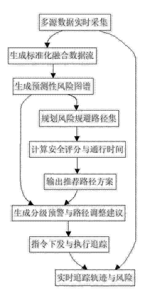
Resumen de: CN122453301A
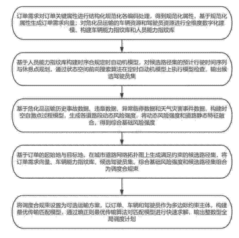
本发明公开了一种危险品道路运输远程电子押运智能监管系统及方法,属于物联网操作系统技术领域,该系统包括数据采集与融合模块,实时采集危险品运输车辆的多源数据,生成标准化融合数据流;运输风险预测评估模块,根据标准化融合数据流,生成预测性风险图谱;路径规划模块,基于预测性风险图谱,生成风险规避路径集,输出推荐路径方案;执行模块,根据预测性风险图谱与推荐路径方案,生成分级预警指令与路径调整建议,同时实时追踪危险品运输车辆的实际行驶轨迹与风险变化,该方法包括步骤T1‑步骤T4。本发明通过运输风险预测评估模块融合历史与实时数据,构建预测性风险图谱,实现了对路段未来事故风险的定量预测与可视化预警。
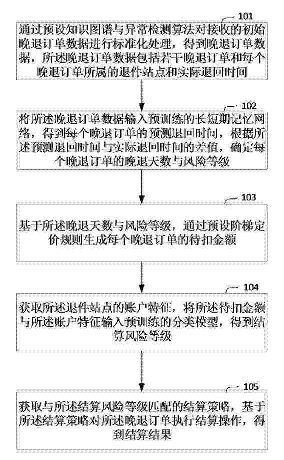
Resumen de: CN122453309A
本发明涉及快递数据处理技术领域,尤其涉及一种晚退快递订单智能结算方法、装置、设备及存储介质,所述方法摆脱了传统晚退考核依赖固定规则与人工处理的主观局限性,通过预设知识图谱与异常检测算法对多源异构晚退数据进行标准化处理,结合长短期记忆网络对退回时效进行动态预测与晚退天数智能计算,实现晚退考核的客观量化与主动防控;借助阶梯定价规则与分类模型的结算风险预判机制,确保待扣金额的精准核算与结算执行的差异化适配;所述方法解决了现有晚退考核中数据治理缺失、结算失败频发等问题,降低了晚退考核的人力成本与时间成本,提高了考核结果的准确性与公正性,为快递行业晚退管理提供了系统性的技术支撑。
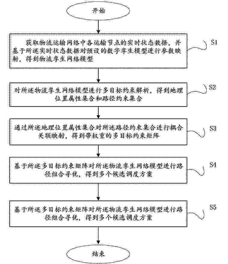
Resumen de: CN122453290A
本发明涉及一种基于数字孪生的物流网络动态优化方法及系统,包括以下步骤,获取运输节点实时状态并映射至数字孪生模型,构建物流孪生网络模型;解析该场景得到多目标约束矩阵;据此进行路径组合寻优,生成多个候选调度方案;量化计算各方案调度指标得出评分,依据评分选定目标调度方案,实现复杂约束下的物流精准调度,解决了传统方案中往往根据静态模型和周期性更新的技术方案无法实时响应运输节点状态的瞬时变化,导致生成的调度方案与实际运行场景存在显著的时间滞后和偏差的技术问题。
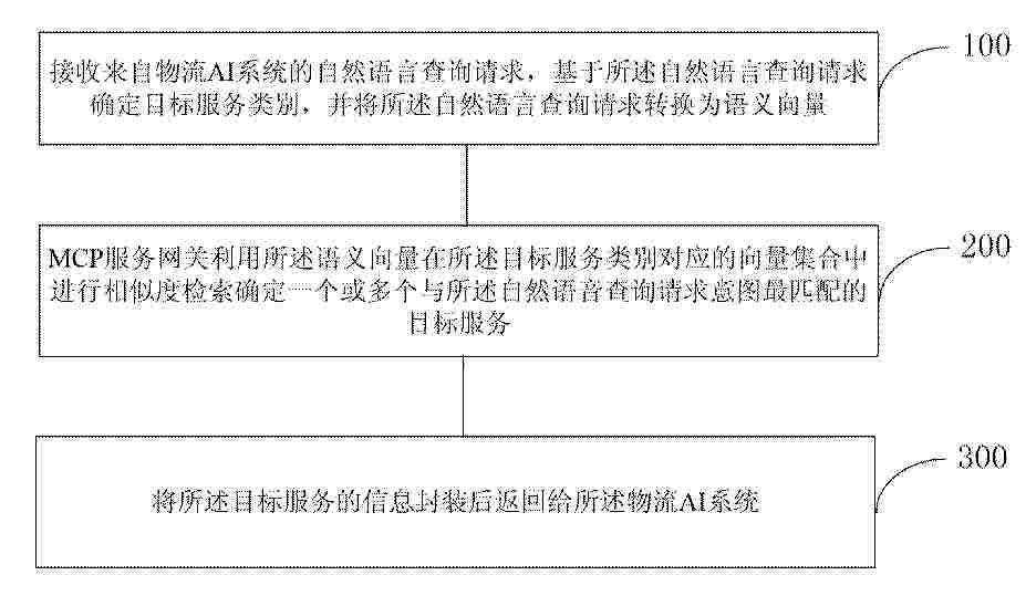
Resumen de: CN122453297A
本发明公开了基于物流AI系统与机器人协同的调度方法、装置,其中方法包括:接收来自物流AI系统的自然语言查询请求,基于所述自然语言查询请求确定目标服务类别,并将所述自然语言查询请求转换为语义向量;MCP服务网关利用所述语义向量在所述目标服务类别对应的向量集合中进行相似度检索确定一个或多个与所述自然语音查询请求意图最匹配的目标服务;将所述目标服务的信息封装后返回给所述物流AI系统。本发明能够提高决策准确率以及提升响应速度;实现了业务事件到物理执行的端到端自动化,上下文处理成本得到了大幅下降。
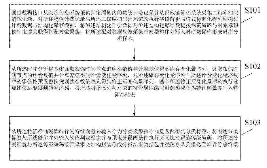
Resumen de: CN122453311A
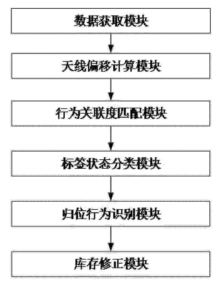
本申请实施例提供一种基于数据分析模型的三级库使用行为分析方法及装置,通过多源数据采集、字段标准化与主键关联构建时序分析样本,结合库存与计费变化量序列提取、零值修正填充与逐点斜率比值运算构建行为特征向量,并通过行为分类模型向量匹配、分段阈值区间比对得到分类标签与等级编码后封装为分析结果数据包经消息队列推送至库存管理终端,有效解决了传统技术在多源异构数据融合构建、使用行为特征量化建模以及分类判级与结构化结果推送等方面的不足,为医院三级库物资使用行为的智能化分析与精准库存管理提供了技术保障。
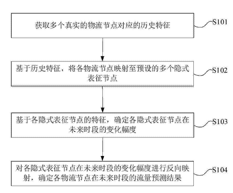
Resumen de: CN122453292A
本申请涉及城市物流预测技术领域,提供一种物流节点的流量预测方法和装置。该方法包括:获取多个真实的物流节点对应的历史特征;基于历史特征,将各物流节点映射至预设的多个隐式表征节点,隐式表征节点的数量小于物流节点的数量;基于各隐式表征节点的特征,确定各隐式表征节点在未来时段的变化幅度;对各隐式表征节点在未来时段的变化幅度进行反向映射,确定各物流节点在未来时段的流量预测结果。本申请提供的物流节点的流量预测方法可以提升动态物流网络预测的泛化性、精准性与高效性,从而更好地满足即时配送、共享出行和城市物流调度等场景中的在线部署需求。
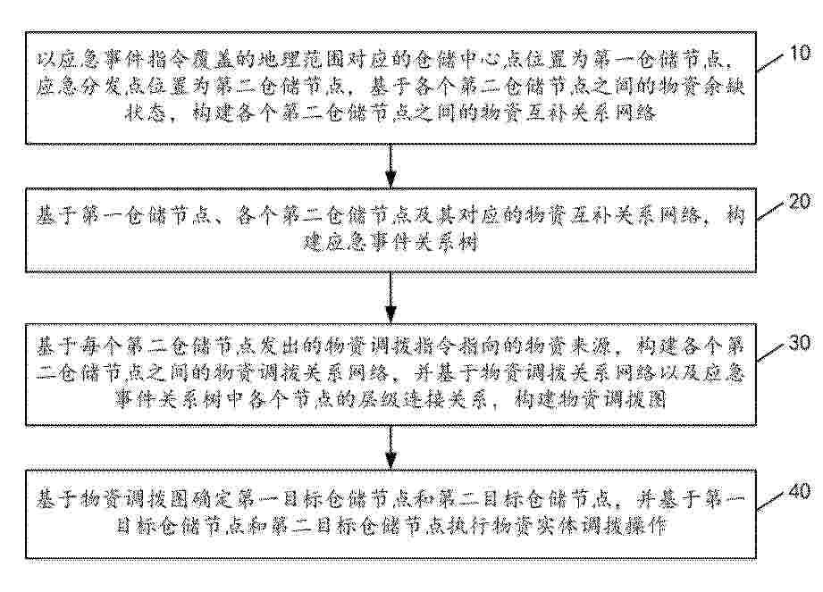
Resumen de: CN122453317A
本发明提供一种面向应急事件的仓储虚拟节点生成方法及装置,该方法包括:以应急事件指令对应的仓储中心点位置为第一仓储节点,应急分发点位置为第二仓储节点,基于各个第二仓储节点之间的物资余缺状态,构建物资互补关系网络;基于第一仓储节点、各个第二仓储节点及其对应的物资互补关系网络,构建应急事件关系树;基于每个第二仓储节点发出的物资调拨指令指向的物资来源,构建物资调拨关系网络,并基于物资调拨关系网络以及应急事件关系树中各个节点的层级连接关系,构建物资调拨图;基于物资调拨图确定第一目标仓储节点和第二目标仓储节点,并基于第一目标仓储节点和第二目标仓储节点执行物资实体调拨操作。本发明提升了应急响应效率。
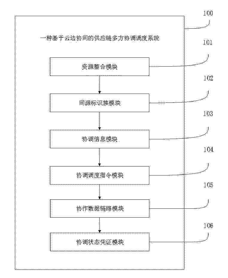
Resumen de: CN122453094A
本发明涉及物流管理技术领域,揭露了一种基于云边协同的供应链多方协调调度系统,该系统中包括资源整合模块、同源标识族模块、协调信息模块、协调调度指令模块、协作数据链路模块及协调状态凭证模块;资源整合模块将供应端本地运行数据封装为实时运行快照,并与本地协调标识组合为协同感知信息集。同源标识族模块对自协商标记溯源得到同源标识族。协调信息模块将异构运行数据映射至全局信息,得到全局协调信息集。协调调度指令模块构建冲突关系图谱并生成协调调度指令集。协作数据链路模块将指令拆解为协作执行指令并建立协作数据链路。协调状态凭证模块同步状态并生成协调状态凭证。本发明可以提高基于云边协同的供应链多方协调调度的效率。
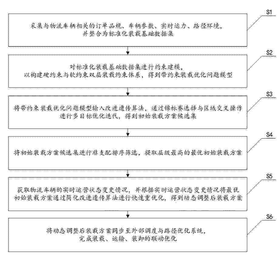
Resumen de: CN122443980A
本申请公开了一种物流车辆的装载率优化方法及系统,涉及物流技术领域,方法针对物流车辆装载率偏低、装载方案依赖人工规划、方案与实时运营脱节等问题,采用标准化数据融合、双层约束建模、改进遗传算法相结合的多目标优化方法,实现装载率的精准优化与动态适配,有效提升物流装载的科学性与协同效率。方法依次通过构建标准化数据底座;建立双层装载约束体系;通过改进遗传算法实现多目标全局搜索;以非支配排序筛选最优平衡解;根据实时变更触发快速重优化;将方案同步至调度与路径系统实现协同联动。方法以数据驱动替代人工经验,多目标优化平衡装载率、货损风险与装卸效率,实时响应机制适应运营场景变化,提升物流装载的科学性与协同效率。
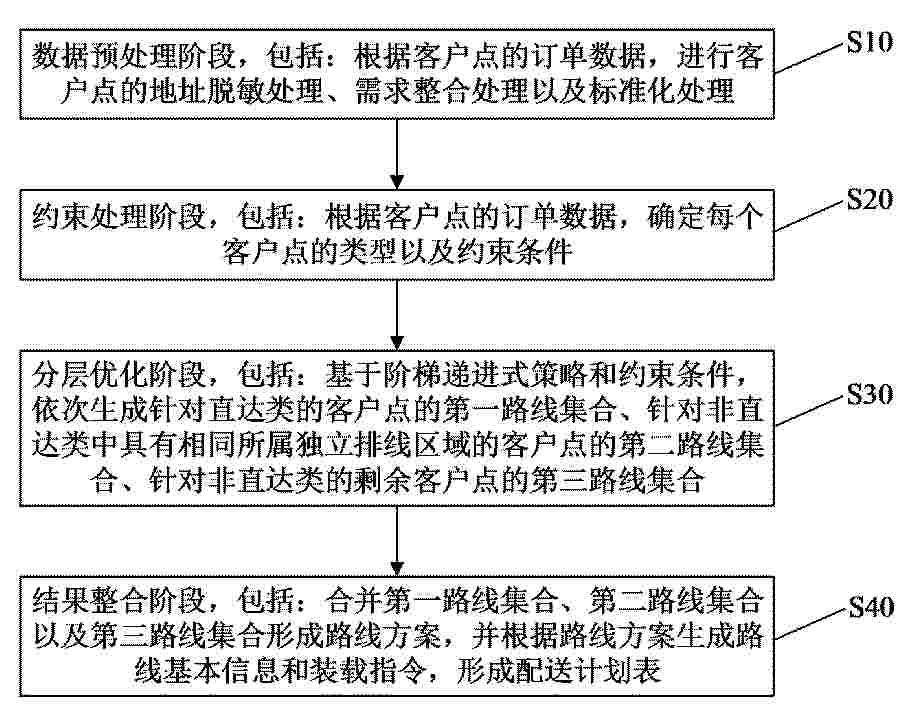
Resumen de: CN122453308A
本公开提供了一种基于多约束的智能装车与排线方法和装置,该方法包括:数据预处理阶段、约束处理阶段、分层优化阶段以及结果整合阶段。本公开通过数据预处理阶段的地址脱敏与托盘化体积估算、约束处理阶段的多类型客户点分类与多约束条件构建、以及分层优化阶段的三阶段递进式求解,实现了复杂业务约束条件下的秒级智能排线,在保护地址隐私的同时保证路径规划精度,并通过直达类专车专送、独立排线区域隔离优化与行政区域分组优化的阶梯处理策略兼顾高优先级客户服务与运营经济性,从而有效降低运输车辆需求、节约运营成本并提升配送准时率与业务安全性。
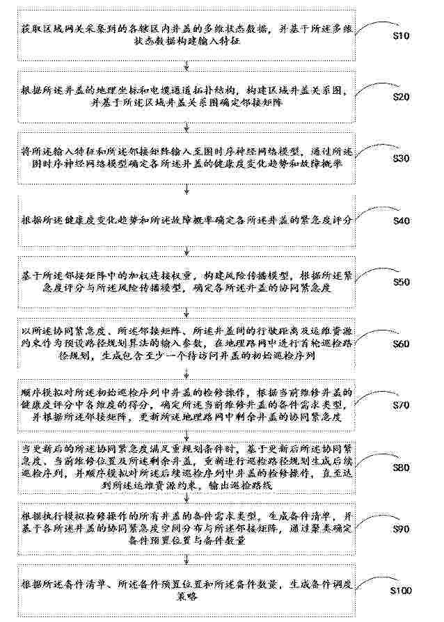
Resumen de: CN122453109A
本申请公开了一种电力井盖的运维方案生成方法、设备及存储介质,涉及电力设备智能运维技术领域。上述方法通过各辖区井盖多维状态数据构建输入特征;再根据井盖地理坐标与电缆通道拓扑结构,构建区域井盖关系图并确定对应邻接矩阵;进而将输入特征与邻接矩阵输入图时序神经网络模型,预测各井盖健康度变化趋势及故障概率,据此计算得到各井盖紧急度评分。然后,结合邻接矩阵构建风险传播模型,更新得到井盖协同紧急度,再基于协同紧急度、地理路网及运维资源约束,动态规划生成最优巡检路线,同时结合模拟检修结果生成备件清单,通过聚类分析确定备件预置位置与数量,最终适配运维场景生成精准的备件调度策略,提升了运维方案的可靠性。
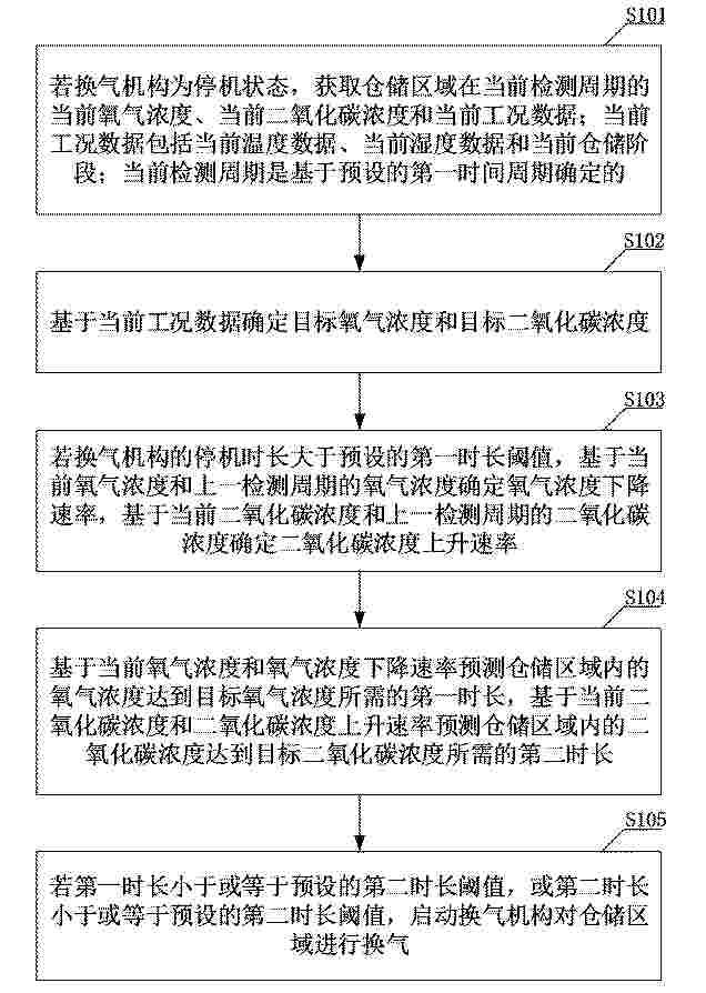
Resumen de: CN122453319A
本申请提供了一种仓储管理方法及装置、电子设备、存储介质,属于智能仓储技术领域,该方法包括:基于当前工况数据确定目标氧气浓度和目标二氧化碳浓度;基于当前氧气浓度和上一检测周期的氧气浓度确定氧气浓度下降速率,基于当前二氧化碳浓度和上一检测周期的二氧化碳浓度确定二氧化碳浓度上升速率;基于当前氧气浓度和氧气浓度下降速率预测仓储区域内的氧气浓度达到目标氧气浓度所需的第一时长,基于当前二氧化碳浓度和二氧化碳浓度上升速率预测第二时长;若第一时长小于或等于预设的第二时长阈值,或第二时长小于或等于预设的第二时长阈值,启动换气机构对仓储区域进行换气。本申请可以实现精准、高效的仓储管理。
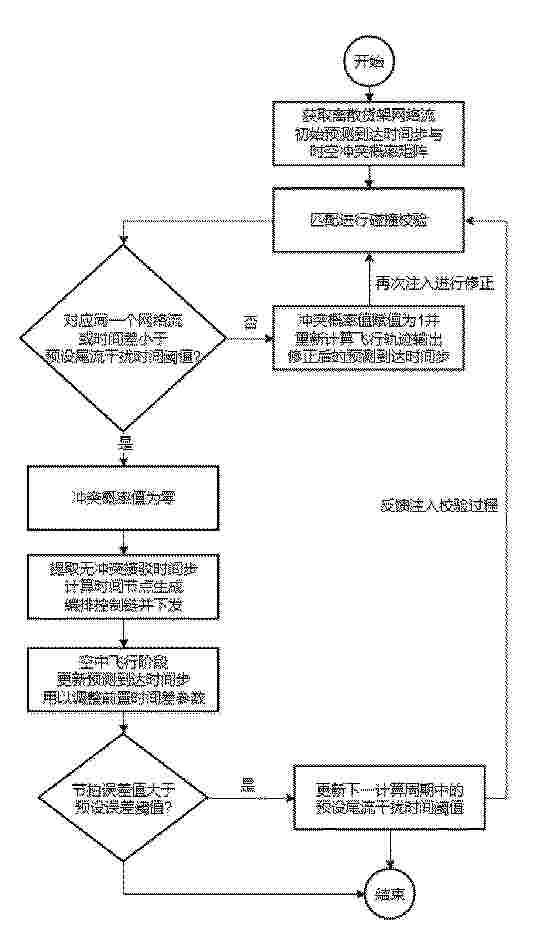
Resumen de: CN122450172A
用于物流配送的无人机与地面车辆协同调度方法及系统,涉及物流运输管理领域;获取离散货架网络流、无人机初始预测到达时间步与时空冲突概率矩阵;将初始预测到达时间步与离散货架网络流匹配进行碰撞校验,当存在车厢抢占或小于预设尾流干扰时间阈值时,将冲突概率值赋值为1并重新规划飞行轨迹,直至冲突概率值收敛为零;基于冲突概率值为零的矩阵生成包含前置时间差参数的编排控制链并下发至地面车辆以分时释放无人机;在飞行阶段动态微调尚未释放车辆的前置时间差参数;在挂载阶段根据挂载节拍误差值自适应更新下一周期的预设尾流干扰时间阈值。本发明消除了时间滑移与尾流干扰对空域安全的非线性干扰,提升了配送资源调度的可靠性。
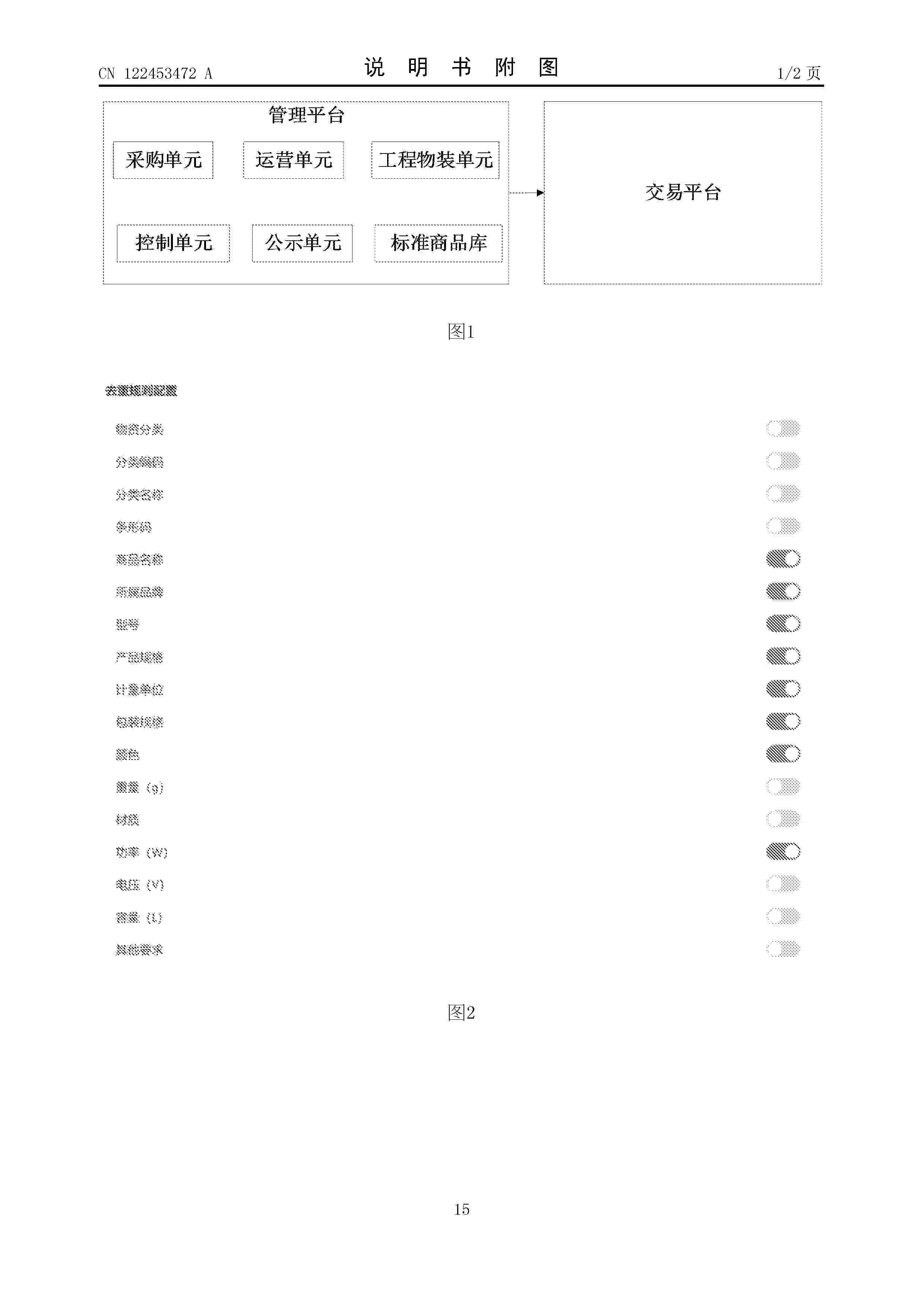
Resumen de: CN122453472A
本发明公开了一种电商业务管理系统,包括管理平台和交易平台,管理平台设置有控制单元、运营单元和标准商品库;控制单元用于,监控到标准商品库中的商品满足基准价更新条件时,生成基准价更新的任务并发送给运营单元;基于从运营单元接收到的商品的多个参考链接的参考价格,结合各参考链接对应电商的权重,确定主流电商价格;根据商品当前各购买链接对应电商的权重和原始竞价,确定历史价格;确定商品的更新后基准价,发送给交易平台,使其基于更新后基准价更新商品的购买链接。该系统综合商品的当前主流电商价格和历史竞价,对商品基准价进行合理更新,使得最终上架的购买链接售价更为合理,性价比更高。
Resumen de: CN122453021A
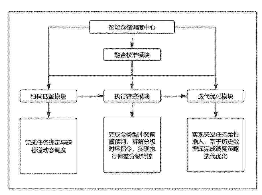
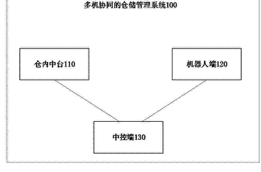
本发明涉及工业数据管理技术领域,公开了一种智能仓储管理的叉车协同调度管理方法及系统,包括:采集仓储空间、设备档案、环境工况全维度基础数据,纳入叠加全局时间基准轴的三维空间坐标系,构建三维时空数字孪生底座,通过五类终端采集动态数据,完成主数据与辅数据融合校准;对接多系统接收全类型作业任务并完成前置校验,构建三类可调度资源子池,完成任务绑定与跨巷道动态调度;构建以全局时间轴为横轴、三维空间节点为纵轴的时空冲突矩阵,完成全类型冲突前置预判,拆解分级时序指令,实现执行偏差分级管控;完成全场景异常三级分类与分级自适应处置,设置窄巷道故障专项应急方案,基于历史数据库完成调度策略迭代优化。
Resumen de: CN122453286A
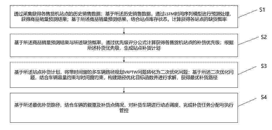
本发明公开一种基于人工智能的智能售货机补货路径优化调度方法及系统,本方法先采集各售货机站点历史销售数据,通过LSTM时间序列模型开展预测处理,得到商品销量预测结果,结合站点库存状态计算获得缺货概率。依据销量预测结果与缺货概率,利用优先级评分公式确定各站点补货优先级并生成补货计划。基于补货计划将带时间窗的多车辆路径规划VRPTW问题转为二次优化问题,结合车辆容量与时间窗约束构建目标函数并求解,得到最优补货路径。依据最优补货路径,结合车辆载重与补货点情况对补货车辆进行动态调度,完成任务分配与执行管控。本发明解决了现有技术存在的销量预测精度不足、补货优先级判定缺乏量化依据、路径优化未兼顾服务可靠性等问题。
Resumen de: CN122453421A
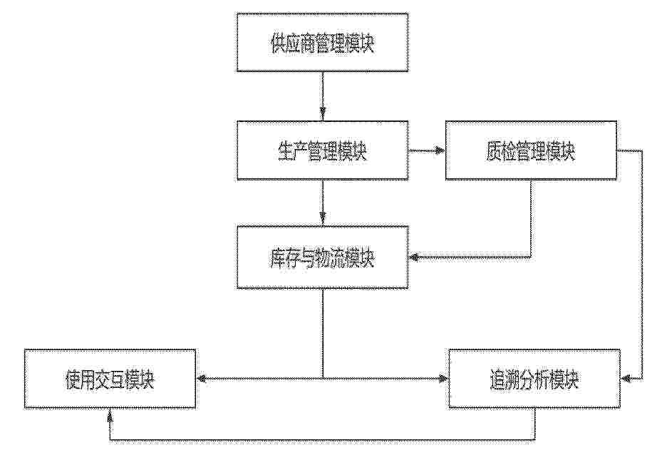
本发明涉及全流程追溯技术领域,具体公开了一种面向GMP合规的培养基全流程追溯系统。本发明基于供应商对己方的历史供货数据计算动态绩效评分,检测到供应商资质临期或供应商动态绩效评分警告超时则由智能合约自动冻结新订单并触发采购任务,实现了供应商质量的前置管控;本发明基于质检管理模块的缺陷分布图、生产管理模块的设备报警记录以及供应商管理模块的供应商动态绩效评分进行比对,应用贝叶斯网络计算各环节的责任概率并输出可量化的定责报告,一定程度上消除了人工经验误差;本发明构建图数据库正向追溯链和反向追溯链,可快速查询所有使用该原材料的成品批次及客户清单,召回响应快。
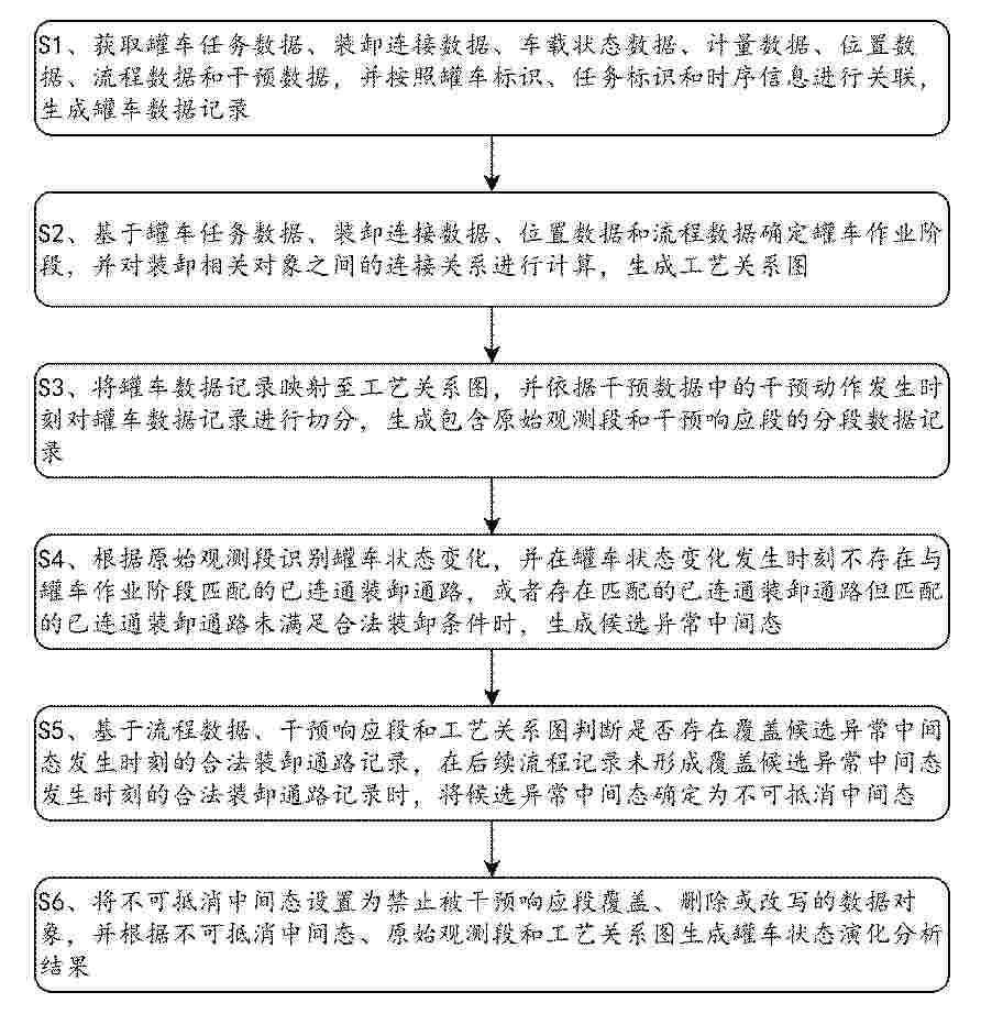
Resumen de: CN122453298A
本发明公开了罐车多源异构数据集成管理与智能分析方法及系统,涉及罐车运输过程数据分析技术领域,方法获取罐车任务数据、装卸连接数据、车载状态数据、计量数据、位置数据、流程数据和干预数据,生成罐车数据记录;根据装卸相关对象连接关系生成工艺关系图,并依据干预动作发生时刻划分原始观测段和干预响应段;从原始观测段识别液位、压力、阀门、铅封、计量和驻停状态变化,结合已连通装卸通路、任务激活状态和作业阶段许可状态生成候选异常中间态;再根据时点覆盖结果和后续解释结果确定不可抵消中间态,并通过中间态锁定记录和只读关联记录生成罐车状态演化分析结果;减少后续流程或干预响应数据对异常中间态的反向覆盖。
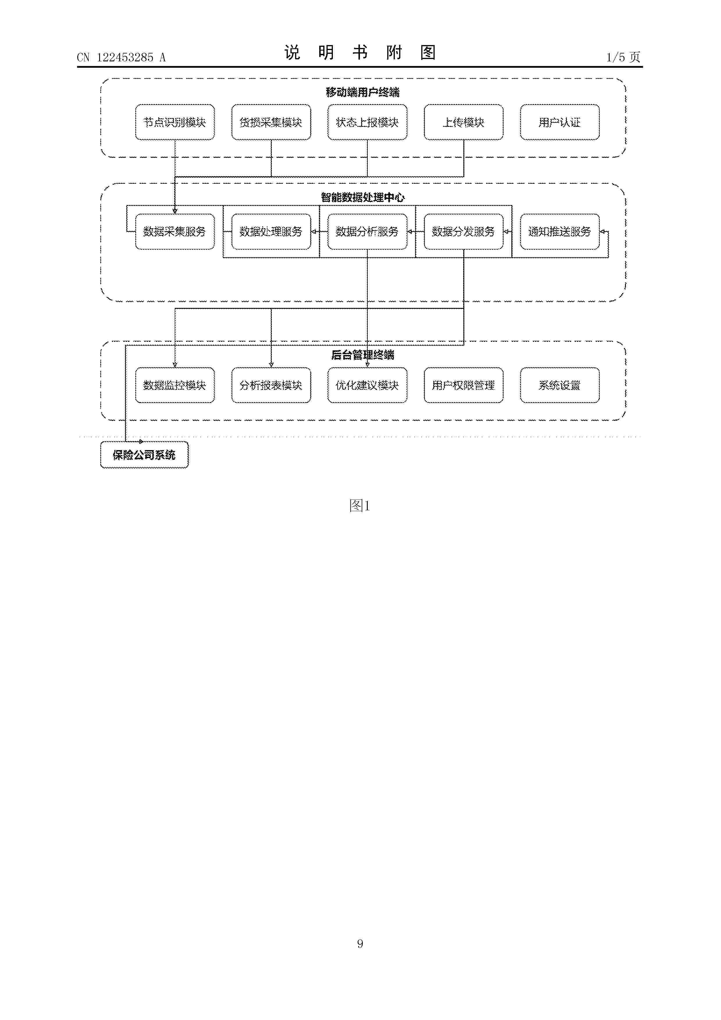
Resumen de: CN122453285A
本发明公开了一种全链路物流智能协同管理系统,包括:移动端用户终端,配置为供各物流节点的操作人员上传货损信息和到货状态;后台管理终端,配置为供管理员查看全量物流数据并进行分析;智能数据处理中心,配置为接收移动端用户终端上传的物流信息;系统被配置为覆盖库房接卸、仓储、汽运、码头接卸、海运发运、目的港汽运、过驳、仓储八个物流节点,并被配置为支持海运环境和陆运环境的适配。本发明通过全链路覆盖与多环境适配,系统覆盖库房接卸、仓储、汽运、码头接卸、海运发运、目的港汽运、过驳、仓储八个物流节点,并支持海运环境和陆运环境的无缝切换,适应复杂多样的运输场景需求。
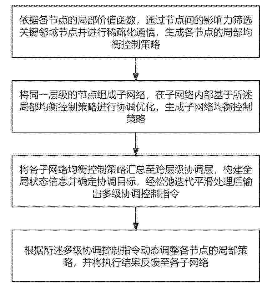
Resumen de: CN122453092A
本发明公开了基于价值函数的电力物资供应链网络均衡控制方法及装置,涉及供应链网络均衡控制技术领域,包括:依据各节点的局部价值函数,通过节点间的影响力筛选关键邻域节点并进行稀疏化通信,生成局部均衡控制策略;将同一层级的节点组成子网络,在子网络内部基于局部均衡控制策略进行协调优化,生成子网络均衡控制策略;并汇总至跨层级协调层,构建全局状态信息并确定协调目标,经松弛迭代平滑处理后输出多级协调控制指令;动态调整各节点的局部策略,并将执行结果反馈至各子网络;本发明解决了现有电力物资供应链管理中局部优化导致全局失衡、层级间协同不足以及面对供需波动和突发扰动时实时响应能力差、控制稳定性低的问题。
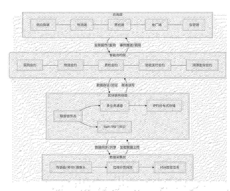
Resumen de: CN122452987A
本申请公开了基于区块链的电厂物资采购溯源与协同管理系统,包括:数据采集层,实时采集物资生产、物流、质检及验收环节的原始数据;区块链网络层,用于存储各环节数据及其哈希摘要,并实现跨组织的数据共享与权限控制;智能合约层,所述智能合约之间通过事件监听机制实现协同,根据业务状态变化自动触发关联合约执行;应用层,用于数据可视化、业务操作与风险预警。本申请通过在供应商车间、物流车辆、质检实验室及电厂仓库部署异构物联网终端与边缘计算单元,结合硬件安全模块与国密算法对数据进行加密签名,并在区块链网络层验证设备身份与数据完整性,确保上链数据源自可信设备且不可抵赖,解决了数据源头可信问题。
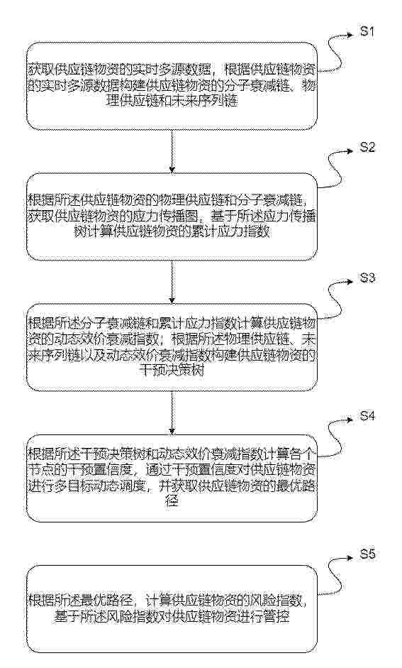
Resumen de: CN122453284A
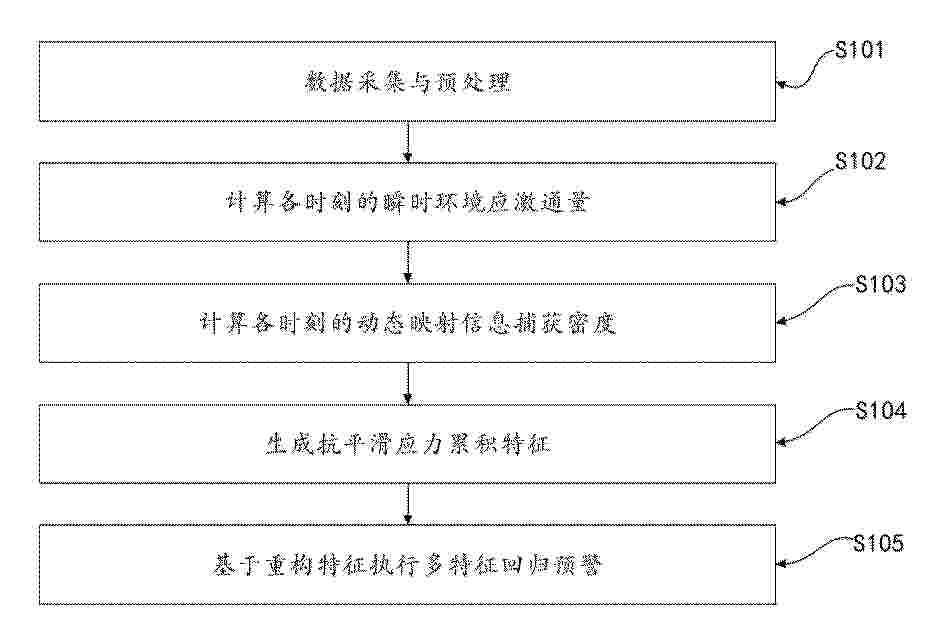
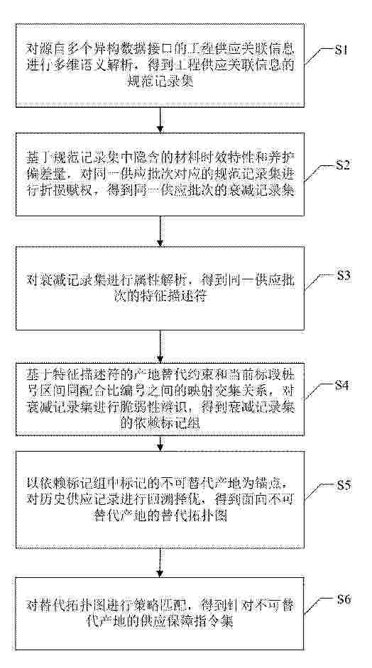
本发明涉及供应链管理技术领域,尤其涉及一种用于一体化供应链物资的动态管控方法及系统。包括以下步骤:S1:获取供应链物资的实时多源数据,根据供应链物资的实时多源数据构建供应链物资的分子衰减链、物理供应链和未来序列链;S2:根据所述供应链物资的物理供应链和分子衰减链,获取供应链物资的应力传播图,基于所述应力传播树计算供应链物资的累积应力指数;S3:根据所述累积应力指数计算供应链物资的动态效价衰减指数;根据所述物理供应链、未来序列链以及动态效价衰减指数构建供应链物资的干预决策树。本发明通过计算供应链物资在运输中的效果指标和干预调度,对供应链物资进行动态管控。
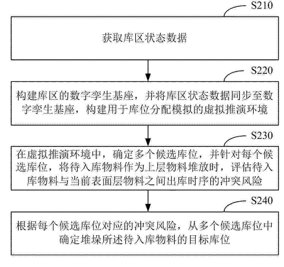
Resumen de: CN122453328A
本申请提供一种物料堆垛库位分配方法及系统,其中,该方法包括:获取库区状态数据;将库区状态数据同步至数字孪生基座,构建用于库位分配模拟的虚拟推演环境;在虚拟推演环境中,确定多个候选库位,并针对每个候选库位,将待入库物料作为上层物料堆放时,评估待入库物料与当前表面层物料之间出库时序的冲突风险;根据每个候选库位对应的冲突风险,从多个候选库位中确定目标库位。通过构建库区的数字孪生基座和虚拟推演环境,能够实时反映库区实际情况,并在虚拟推演环境中,预演不同候选库位的堆垛情况,具备基于出库时序冲突风险的前瞻性预演能力,能够有效规避物料压埋情况,减少不必要的翻堆作业。
Resumen de: CN122453288A
本发明涉及一种考虑配送距离约束的生鲜物流网络可靠性评估方法,属于物流技术领域。该方法有效克服了传统评估手段的局限。首先,该方法能够直接处理各边容量为多状态的网络模型,从而更真实地反映实际生鲜物流网络中运力受多重因素影响而随机波动的特性,提升了评估模型的准确性与实用性。本发明通过集成距离约束的网络最大流算法与分解技术,避免了基于枚举所有极小路的间接算法所带来的计算组合爆炸问题,从而显著提升了在评估较大规模网络时的计算效率。最后,该方法定义并求解的可靠性指标R(d,D)同时兼顾了流量需求与配送距离这两大核心约束,为生鲜物流网络的规划、优化与管理提供了直接、量化的决策依据。
Resumen de: CN122453322A
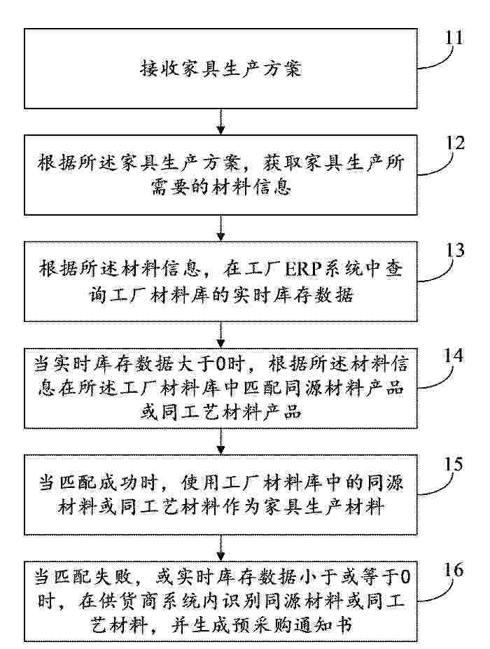
本发明公开了一种家具生产材料信息的处理方法、装置及设备,涉及家具生产制造技术领域,包括:接收家具生产方案;根据所述家具生产方案,获取家具生产所需要的材料信息;根据所述材料信息,在工厂ERP系统中查询工厂材料库的实时库存数据;当实时库存数据大于0时,根据所述材料信息在所述工厂材料库中匹配同源材料产品或同工艺材料产品;当匹配成功时,使用工厂材料库中的同源材料或同工艺材料作为家具生产材料;当匹配失败,或实时库存数据小于或等于0时,在供货商系统内识别同源材料或同工艺材料,并生成预采购通知书。本发明可以实现前端设计与工厂库存及供货商的自动无缝对接,提升材料信息处理效率,降低库存积压,优化资源配置。
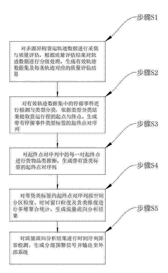
Resumen de: CN122453302A
本发明公开了基于轨迹大数据的货物流量流向分析方法及系统。该方法包括:对多源异构货运轨迹数据进行多维质量评估与分级清洗,生成有效轨迹数据集;对有效轨迹数据集中的停留事件进行多类型识别与分类,提取货运行程起终点,生成带停留事件类型标签的起终点对序列;对起终点对序列进行货物品类推断,生成带货类标签的起终点对序列;对带货类标签的起终点对序列进行多维聚合统计,构建流量流向分析结果;对流量流向分析结果进行时间序列异常检测与分级预警。本发明还公开了实现上述方法的系统。
Resumen de: CN122453323A
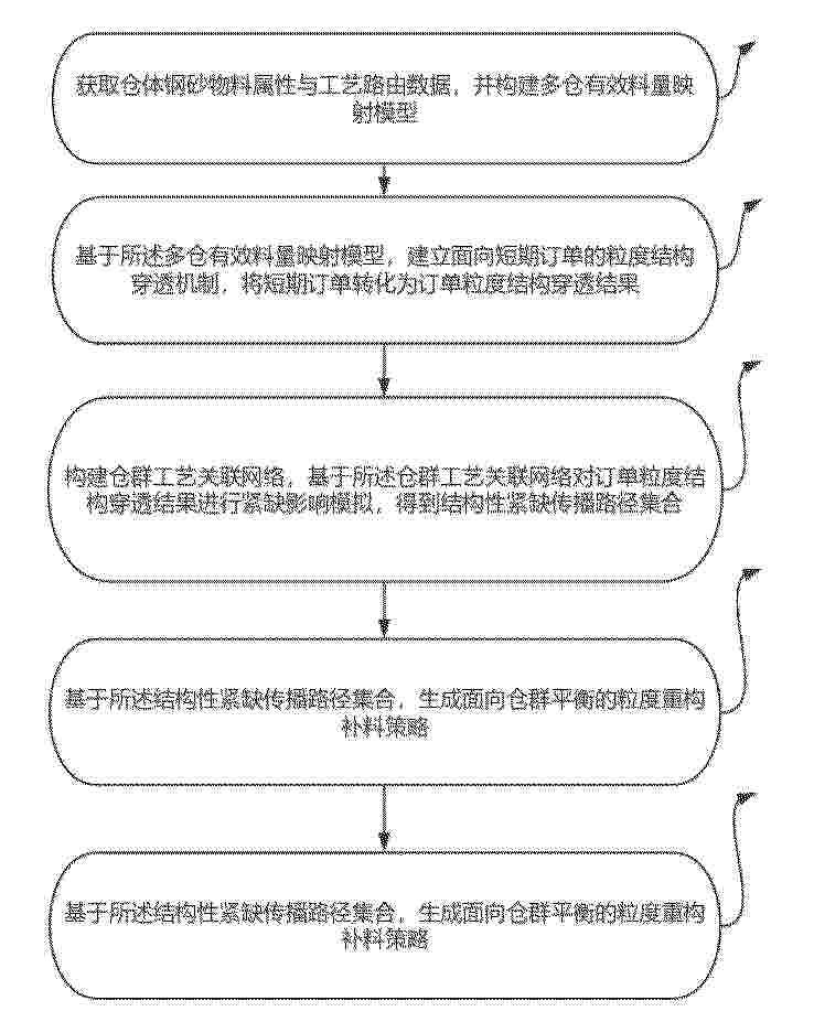
本发明公开了基于RFID和二维码双标识的库位动态管理方法及系统,涉及库位管理技术领域。方法包括:调取历史订单序列和实时订单序列;基于存取便利性的弹性库位分配,得到多个弹性库位单元;部署多个RFID库位标识标签;响应实时订单序列进行储料跨库位动态调仓过程中,进行板材单体身份过程数据写入,并进行多个RFID库位标识标签的写入;执行实时订单序列的加工过程中,对入库余料多视角图像执行空间匹配校验,以进行耐磨损二维码标签更新和多个RFID库位标识标签的关联存储信息刷新。解决了现有技术中库位管理难以根据订单情况进行动态调整,导致仓储调度效率较低的技术问题,达到了提高仓储调度效率的技术效果。
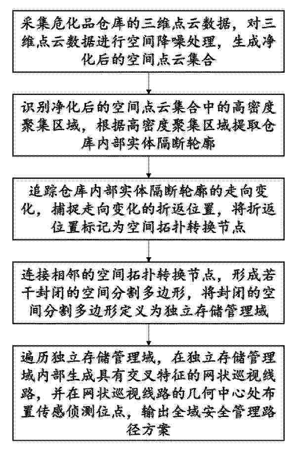
Resumen de: CN122453315A
本发明公开了一种基于危化品仓库存储安全管理系统及方法,涉及危化品仓储安全管理技术领域,包括采集危化品仓库三维点云数据并进行空间降噪,生成净化后的空间点云集合;识别点云中高密度聚集区域提取仓库内部实体隔断轮廓,追踪轮廓走向变化捕捉折返位置并标记为空间拓扑转换节点,连接相邻节点形成封闭空间分割多边形,界定为独立存储管理域;遍历各管理域生成带交叉特征的网状巡视线路,在网状线路几何中心布设传感侦测位点,输出全域安全管理路径方案。本发明通过三维点云处理与空间拓扑分割实现存储域自动划分,结合网状巡视线路与中心传感布设优化管理路径,适配危化品仓库空间安全管理需求。
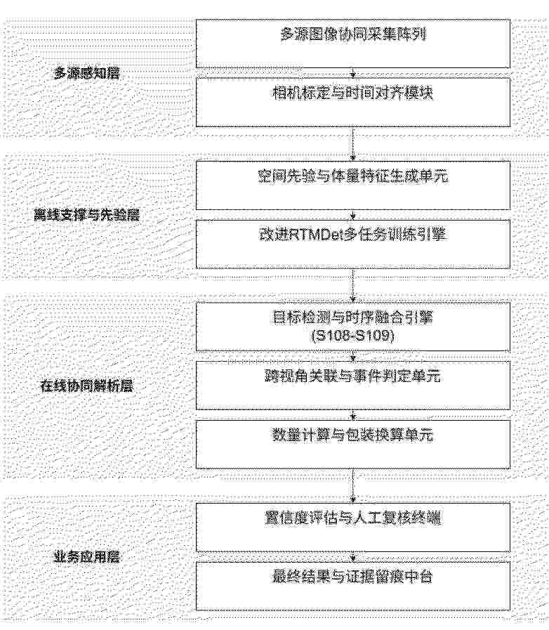
Resumen de: CN122454289A
本发明涉及一种物资出入库视觉统计方法,包括:采集目标物资图像,将所述目标物资图像输入RTMDet检测模型,获取目标物资检测结果;RTMDet检测模型利用训练集通过多任务学习优化改进后的RTMDet网络模型的类别预测与尺度回归获得;训练集包括:原始目标物资检测结果及对应的体量特征;改进后的RTMDet网络模型通过改进RTMDet网络模型的基本构建单元获得;将目标物资检测结果与固定堆区边界信息进行时序融合,获取最终检测结果;固定堆区边界信息利用深度图提取的目标点云数据计算获得。
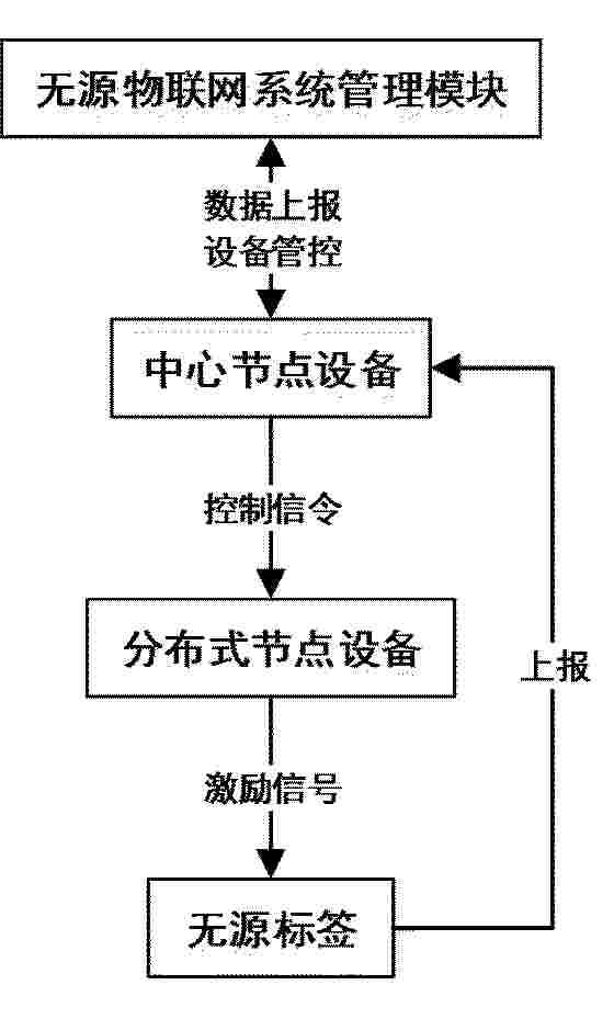
Resumen de: CN122453326A
本发明实施例提供一种基于RFID的智能盘点方法,属于物资管理技术领域。所述基于RFID的智能盘点方法包括:对物资进行赋码贴签管理;针对室内普通货架区域范围小于500m2的仓库,采用单点式无源RFID进行盘点;针对室内普通货架区域范围大于等于500m2的仓库,采用组网式无源RFID进行盘点;针对室内平库区域范围小于500m2的仓库,采用单点式无源RFID进行盘点;针对室内平库区域范围大于等于500m2的仓库,采用组网式无源RFID进行盘点;针对室外堆场的仓库,采用单点式无源RFID、组网式无源RFID或有源RFID进行盘点。该基于RFID的智能盘点方法能够实现物资的自动化高效盘点,快速、准确地掌握库存情况,有效解决登高作业难、盘点效率低的问题,显著提升仓库管理效率。
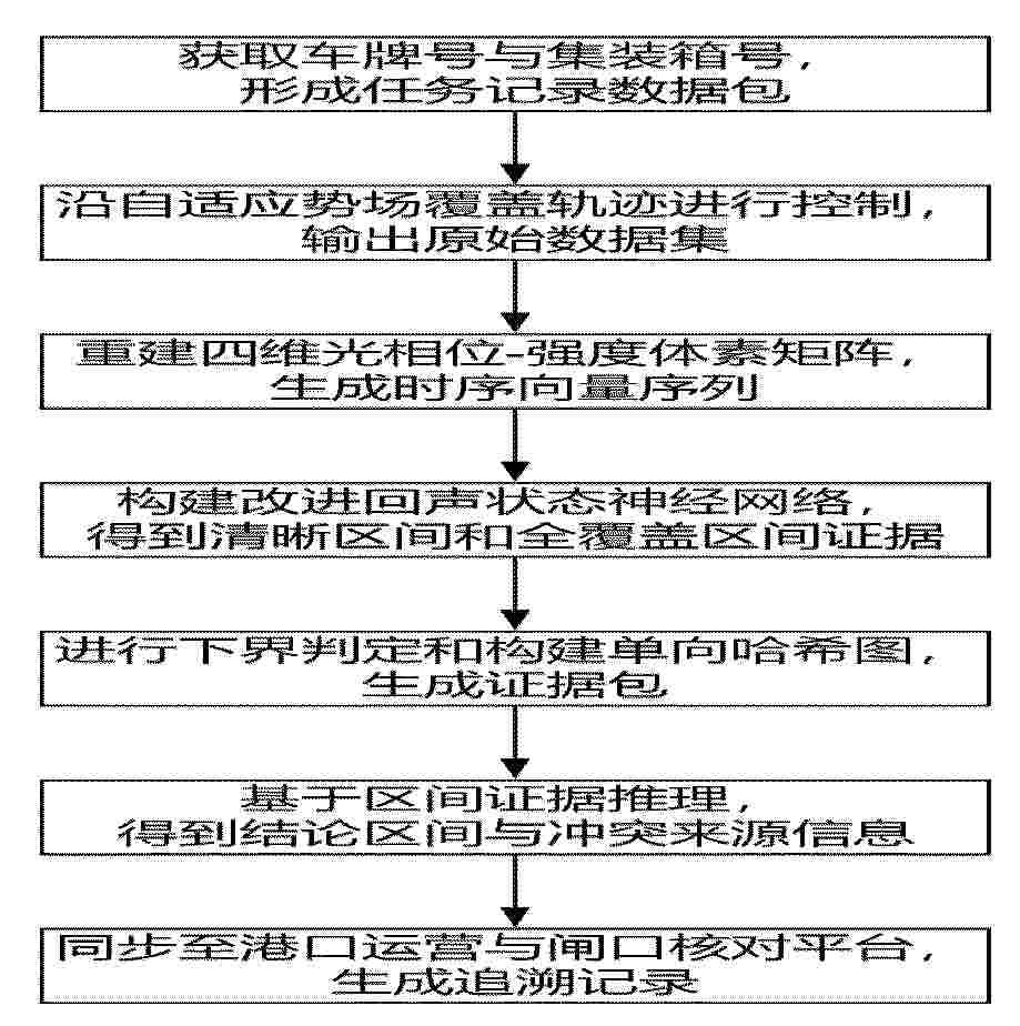
Resumen de: CN122453303A
本发明公开了一种基于多源融合的查验证据智能追溯方法,涉及智能自动化技术领域,包括:获取车牌号与集装箱号,形成任务记录数据包;沿自适应势场覆盖轨迹进行控制,输出原始数据集;重建四维光相位‑强度体素矩阵,生成时序向量序列;构建改进回声状态神经网络,得到清晰区间和全覆盖区间证据;进行下界判定和构建单向哈希图,生成证据包;基于区间证据推理,得到结论区间与冲突来源信息;同步至港口运营与闸口核对平台,生成追溯记录。本发明通过引入改进回声状态神经网络生成区间证据并结合区间证据推理输出结论区间,实现了港口空箱查验的快速核验放行与全链路可追溯。
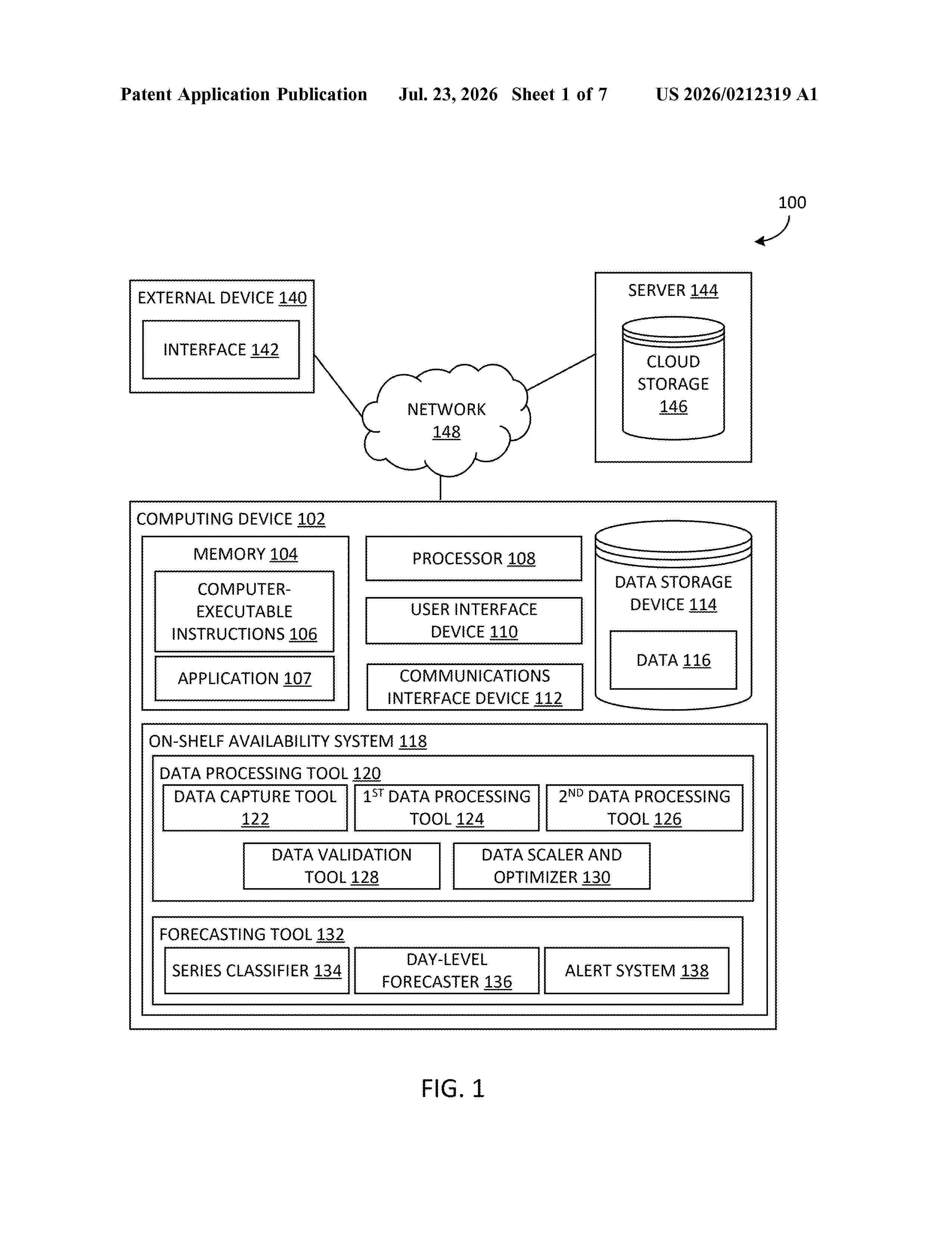
Resumen de: US20260212319A1
Systems and methods for managing on-shelf availability (OSA) and phantom inventory. The method includes determining a classification for one or more products, generating, based on the determined classification, a day-level forecast for the one or more products, generating, based on the generated day-level forecast, an alert associated with the one or more products, the generated alert indicating an on-shelf availability (OSA) issue with the one or more products, and outputting the generated alert.
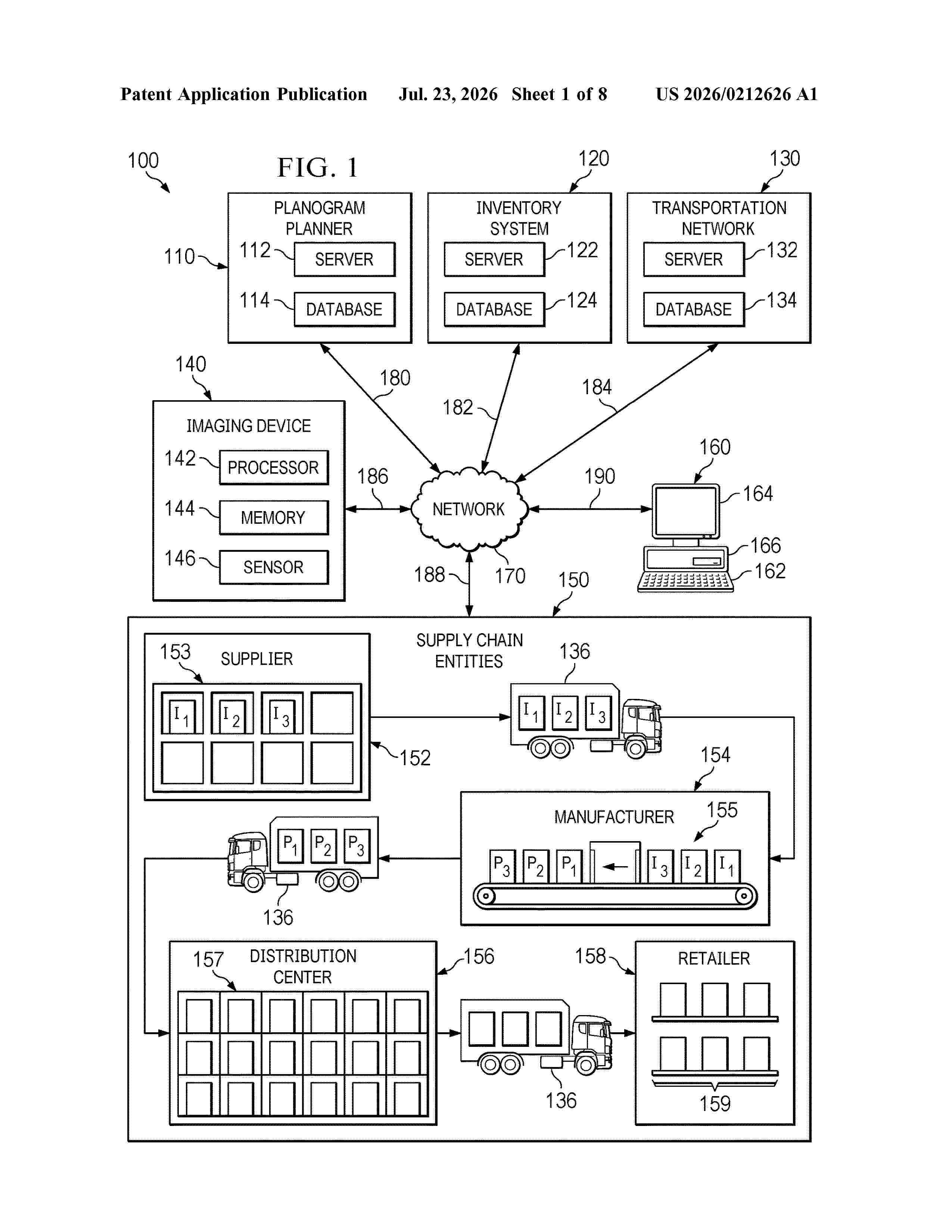
Resumen de: US20260212626A1
0000 A system and method are disclosed for virtual planogram automation comprising receiving, by a planogram planner comprising a server, image data from imaging devices of products prior to the display of the products in a product display area at a retail entity, detecting changes in a product based on the received image data, performing simulated annealing to generate new planogram options by generating a planogram option in response to received image data and one or more received KPI's, incrementing the planogram option according to neighboring states of the planogram parameters, calculating an objective function measuring optimality of the incremented planogram option, repeating the generating, incrementing and calculating steps until a stopping criterion is met according to the objective function, and determining a final planogram based on the stopping criterion being met.
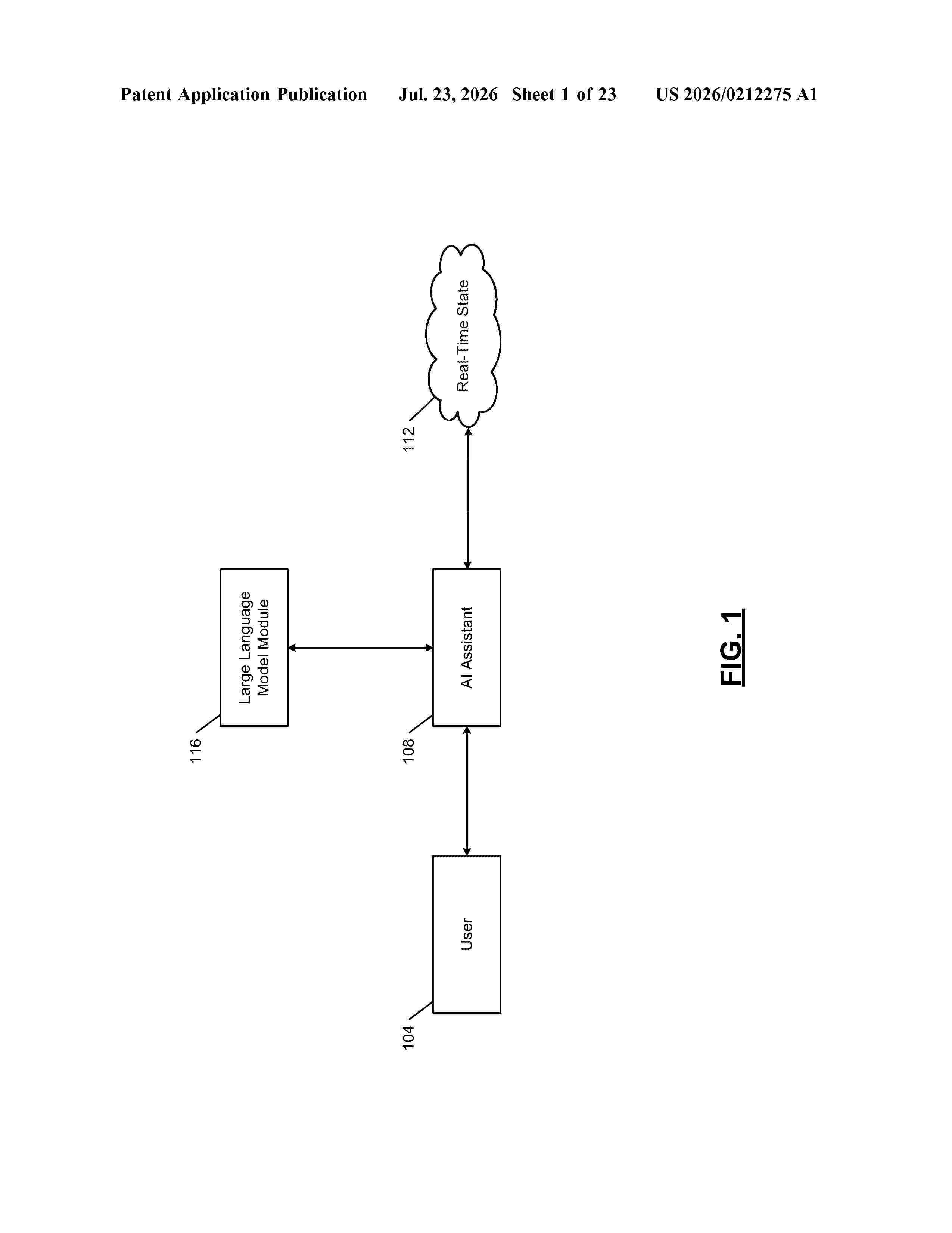
Resumen de: US20260212275A1
A system includes memory hardware storing a defined data structure that specifies a plurality of groups associated with a set of users, schedule data, and relationship data. The system includes a context module configured to determine a default context associated with a first user. The first user is included in a respective set of users of a first group of a plurality of groups. The default context is associated with a subset of the schedule data, a subset of the plurality of groups, and the respective set of users. The system includes a real-time state module configured to determine a first real-time state of the defined data structure. The system includes an action generation module configured to, in response to a determination that an issue exists in the first real-time state of the defined data structure, generate and execute a set of solutions for the issue.
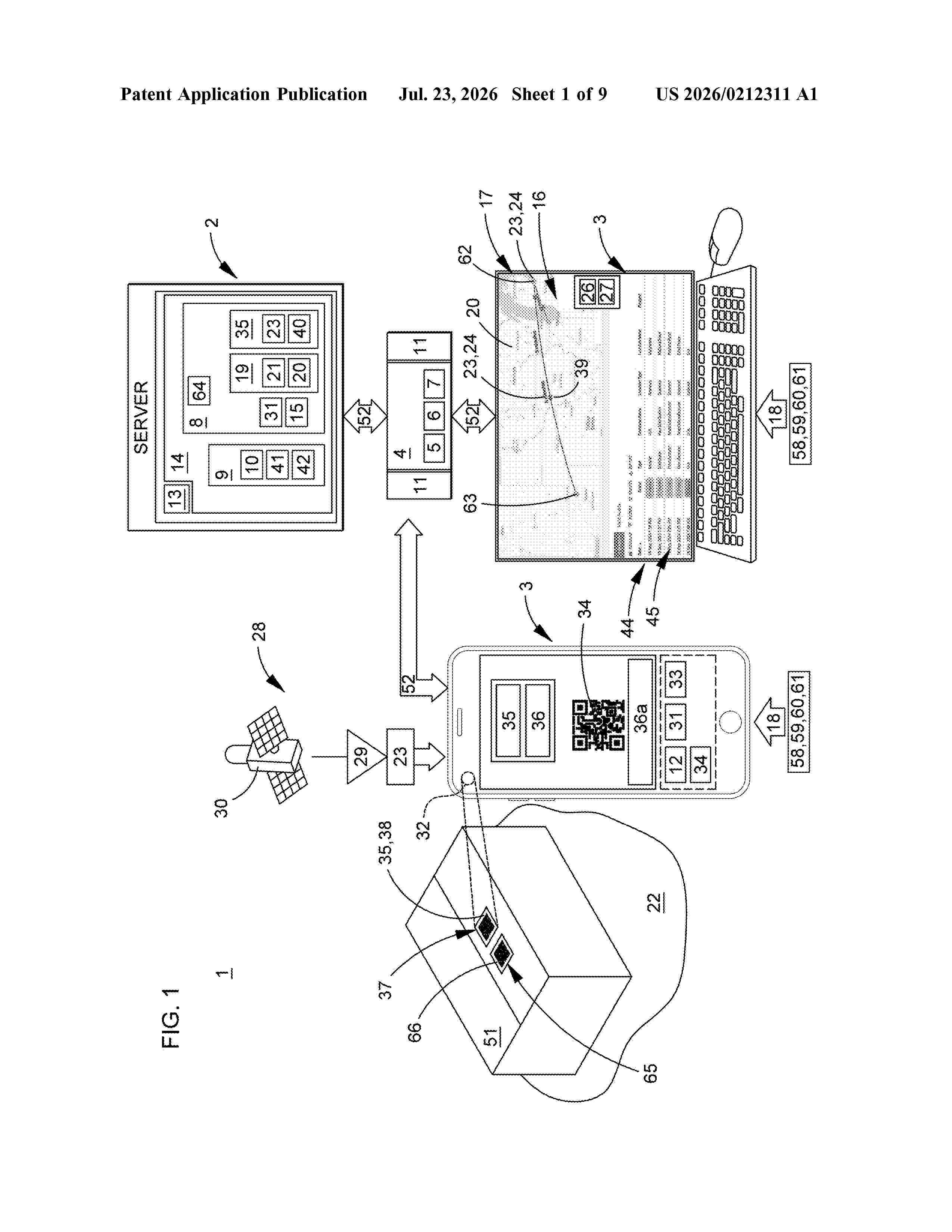
Resumen de: US20260212311A1
A computer implemented supply chain asset tracking system and methods of making and using the computer implemented supply chain asset tracking system to increase asset information flow associated with one or more assets in or between a plurality of tiers in a supply chain.
Resumen de: US20260212316A1
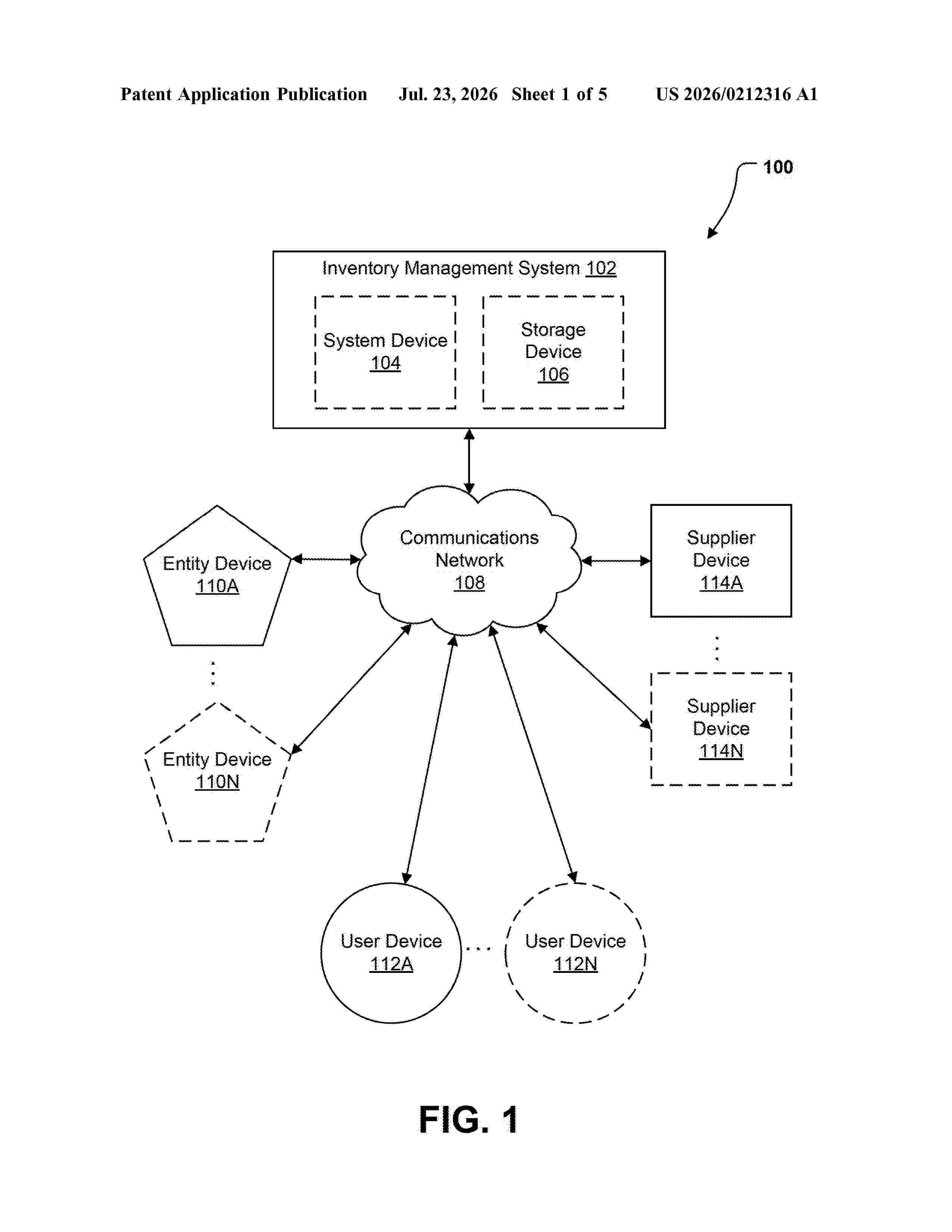
Systems, apparatuses, methods, and computer program products are disclosed for automation of an inventory management system. An example method includes detecting a transaction associated with a configured entity account. The example method further includes identifying a product identifier associated with the transaction. The example method further includes determining, based on the product identifier, a new stock quantity for an offering associated with the configured entity account, wherein the offering is at least one of a product category, a product, and a product component. The example method further includes causing an inventory management database to be updated to reflect the new stock quantity for the offering, wherein the configured entity account is linked to the inventory management database.
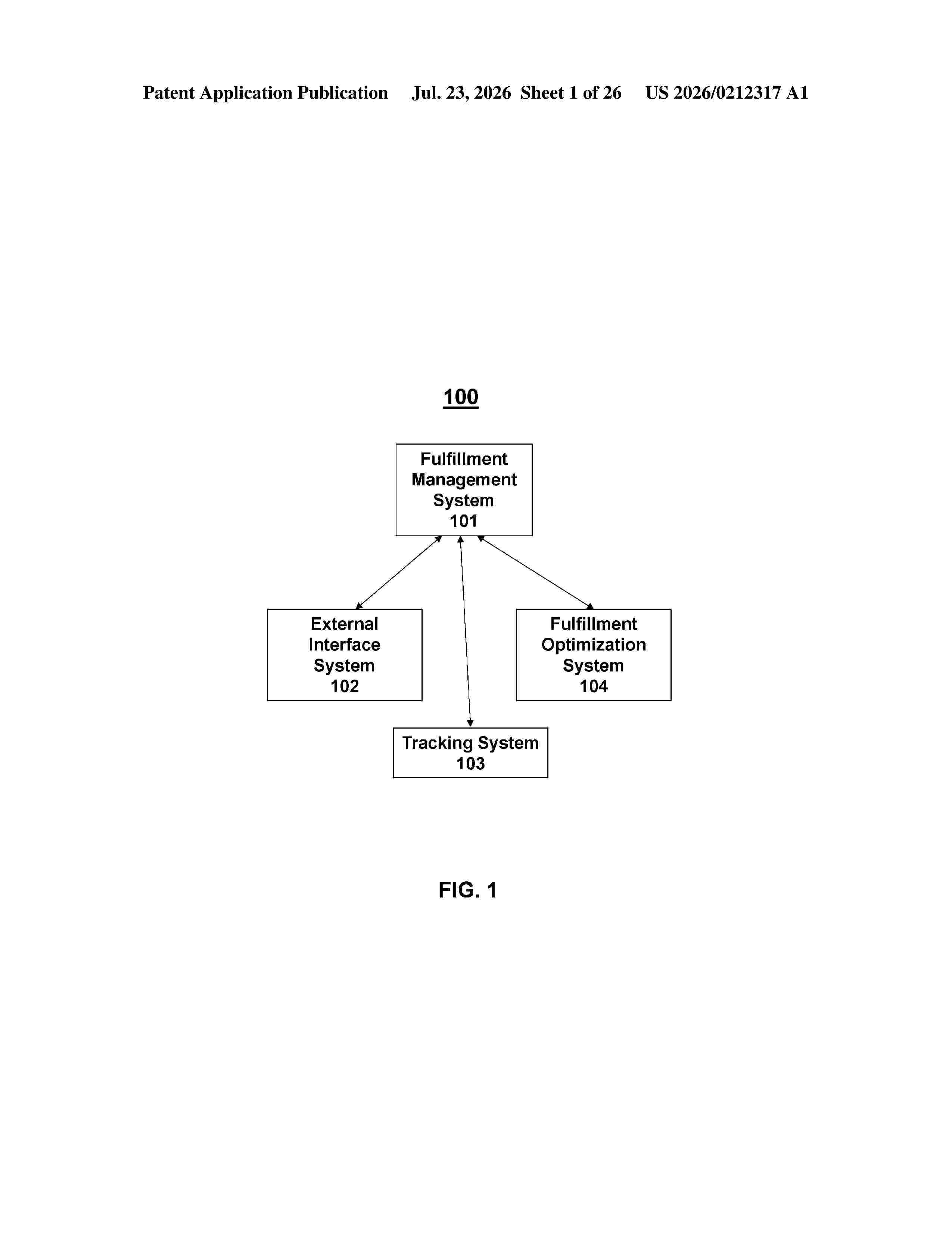
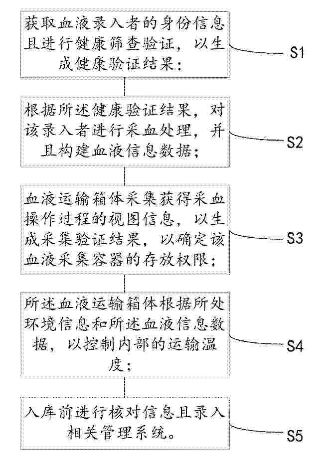
Resumen de: US20260212317A1
A computer-implemented method comprising: providing, on a display associated with a collection device, a request to obtain identifier information associated with each of a plurality of collection containers; receiving the identifier information; updating, on the display, a corresponding graphical element with the identifier information associated with each of the plurality of collection containers; retrieving location information for a particular item on a list of unfulfilled orders and providing the location information for presentation on the display; receiving information indicative of the collection device being at a location corresponding to the location information; transmitting, to the collection device for presentation on the display, information regarding the item and a quantity of the item to be allocated to each collection container; transmitting, to the collection device for presentation on the display, a control configured to indicate a quantity of the particular item allocated in each collection container.
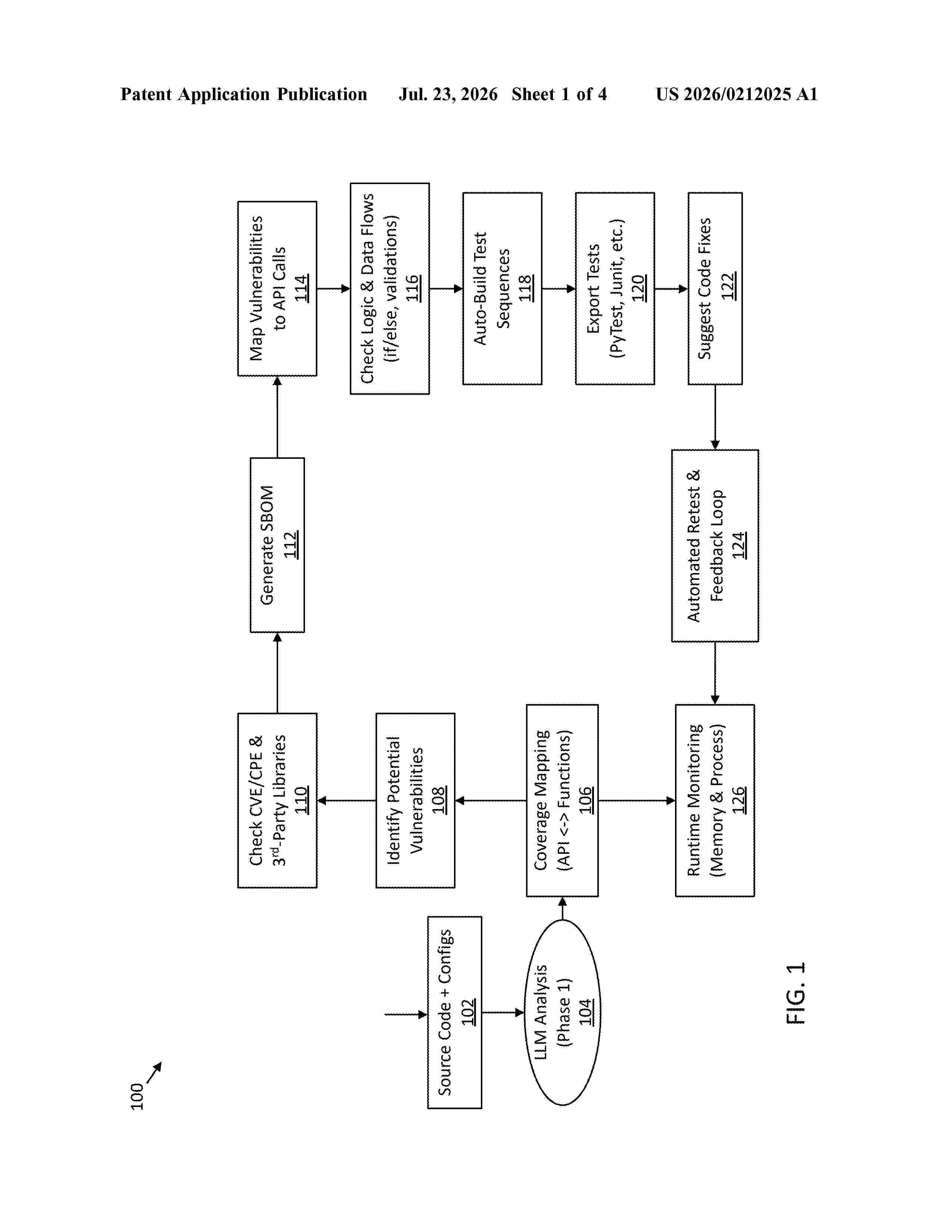
Resumen de: US20260212025A1
0000 A computer-implemented method for application security analysis includes ingesting application data including source code and configuration information, processing the data with a large language model to derive a contextual mapping between external interfaces and internal code portions, identifying security vulnerabilities based on the mapping, associating each vulnerability with at least one mapped code portion and an external interface capable of reaching that portion, automatically generating executable security tests from those associations, executing the tests to produce validation outcomes, and updating at least a portion of the contextual mapping responsive to the outcomes. In certain embodiments, the method accepts user input to refine the mapping and supports export of tests to multiple frameworks, enabling repeatable validation and remediation across evolving deployments.
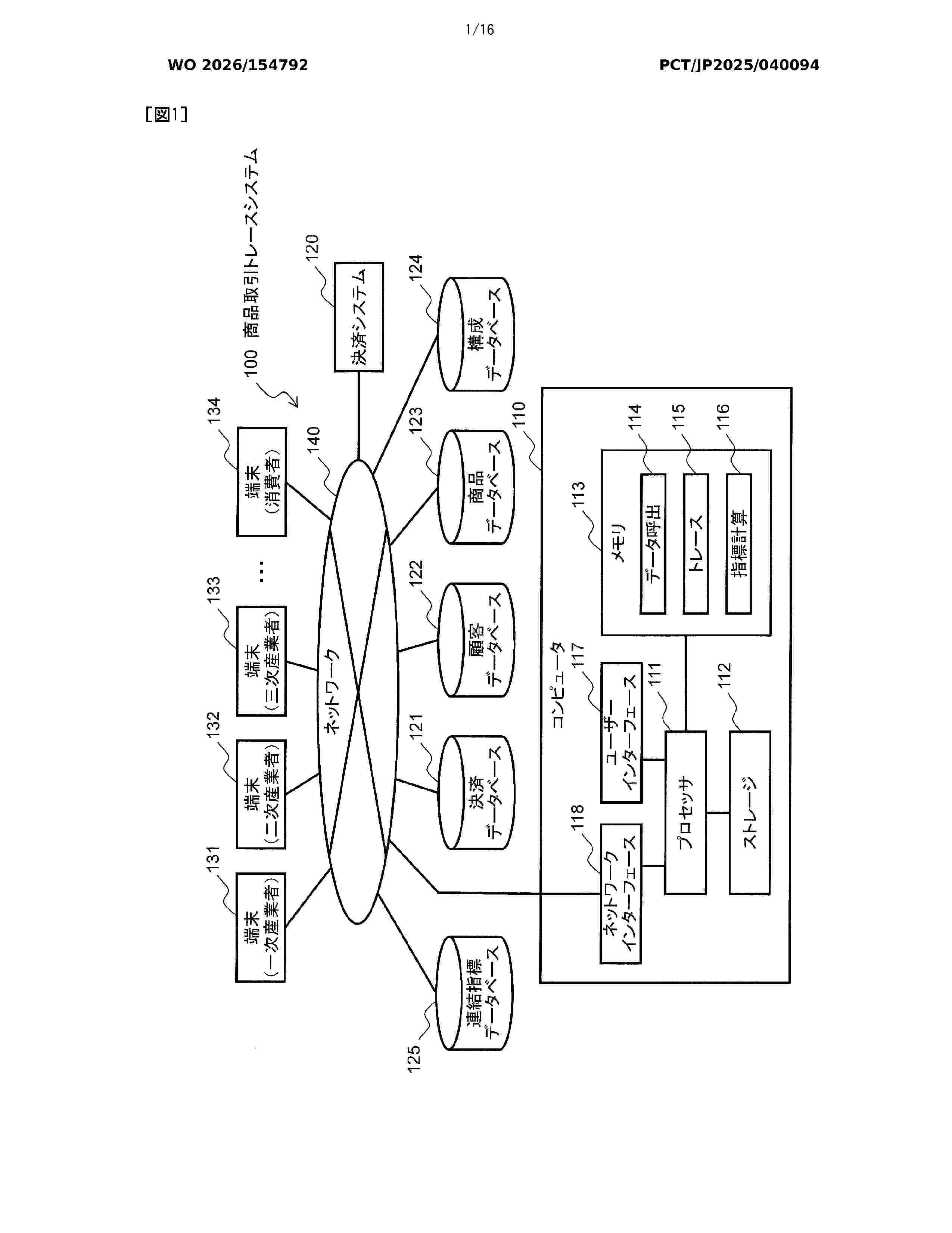
Resumen de: WO2026154792A1
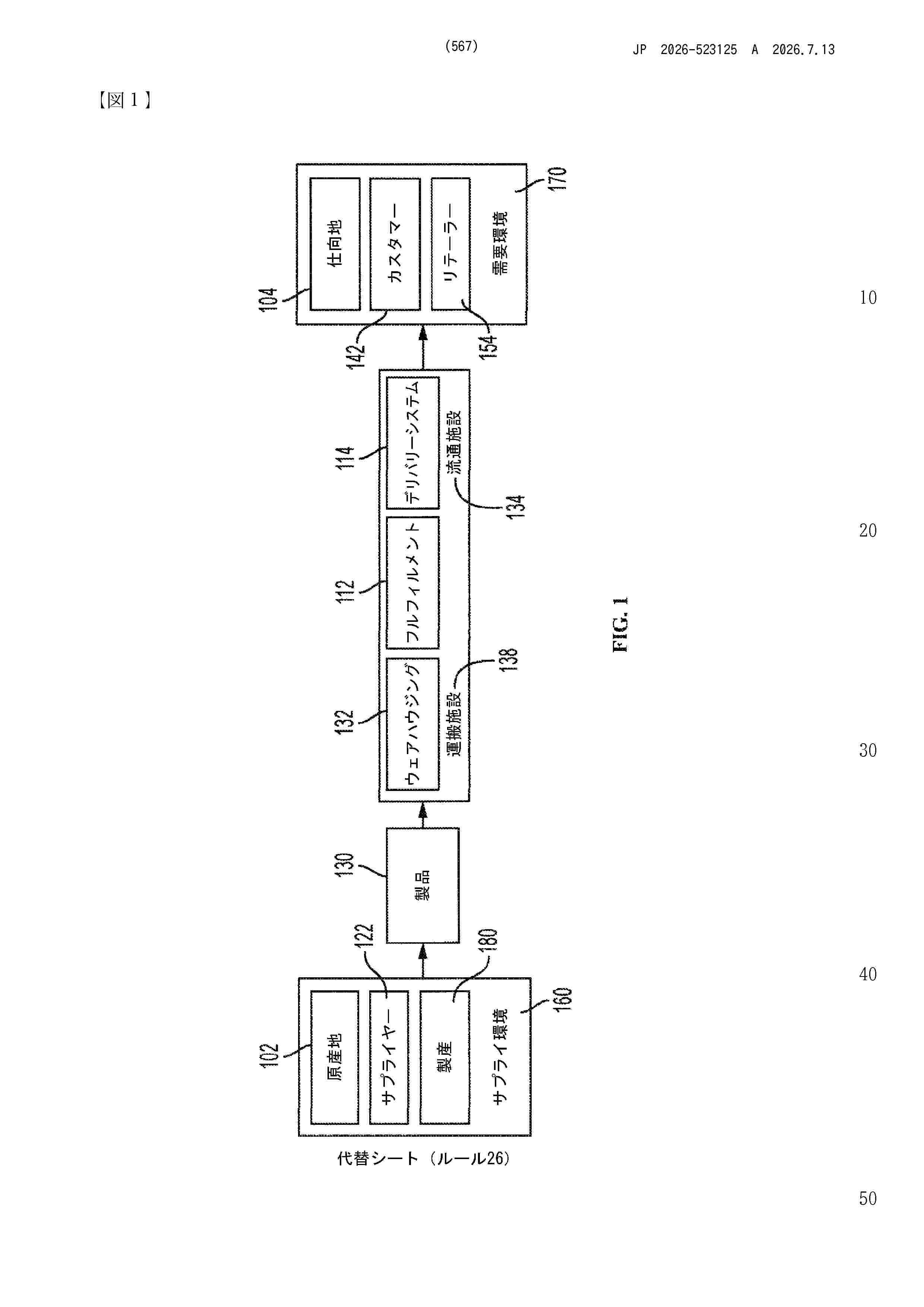
This computer system for presenting an index relating to at least one of environmental, economic, and social aspects of commodity trading performs: generating a commodity trading network constituted by nodes representing business operators or consumers, and edges indicating commodity flows between business operators or between a business operator and a consumer corresponding to the nodes; reading, for a given business operator in the commodity trading network, an index of a shipped commodity shipped by the business operator and an index of a purchased commodity purchased for manufacturing or producing the shipped commodity; executing correction processing that repeatedly performs processing for correcting the index of the shipped commodity along a commercial flow in the commodity trading network by using a mathematical expression including the index of the shipped commodity and the index of the purchased commodity as variables; and generating and outputting information for displaying the indexes in the commodity trading network.
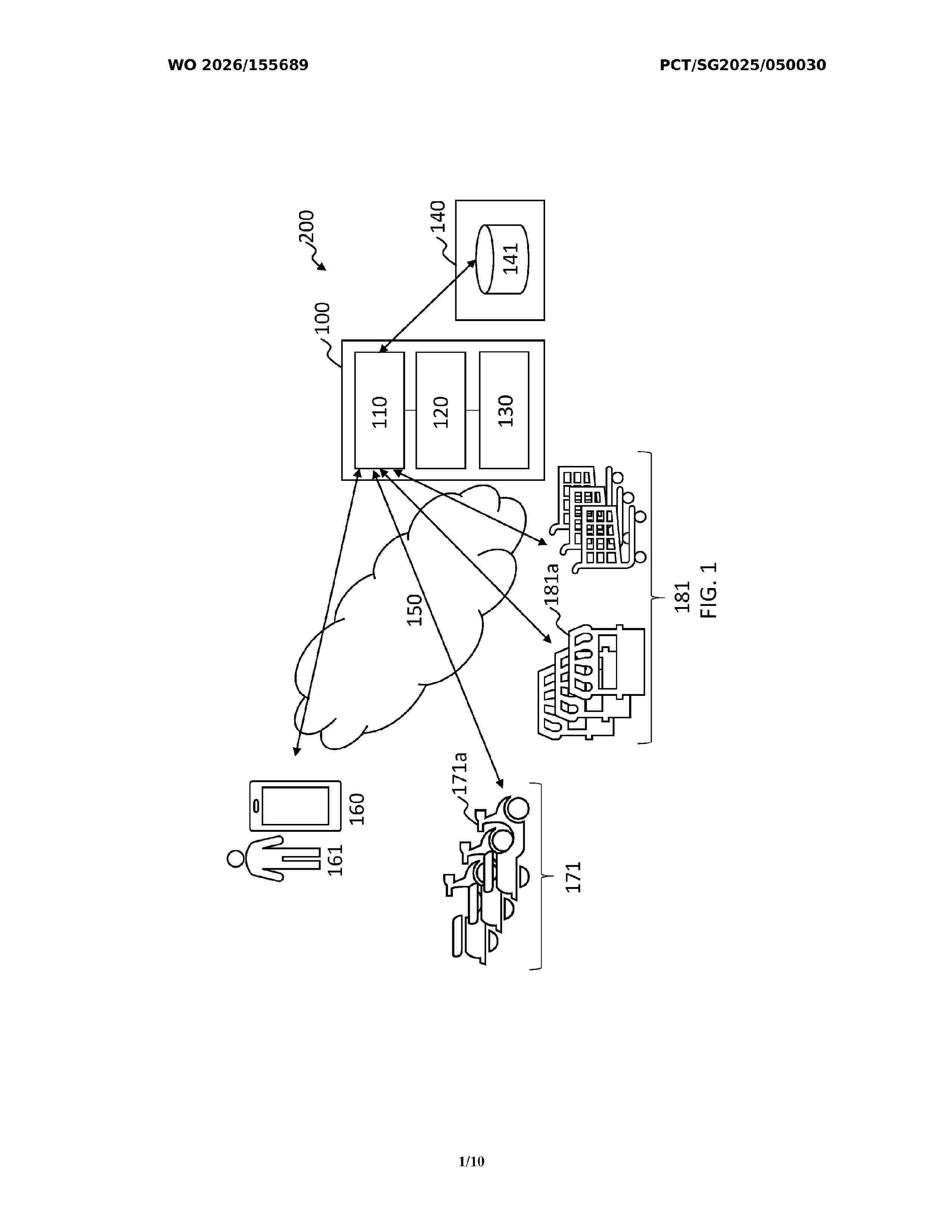
Resumen de: WO2026155689A1
A processor is configured to: compute a first distance between a first pick-up location of a first order and a second pick-up location of each order of a plurality of orders, a second distance between a first drop-off location of the first order and a second drop-off location of the order, and a creation time difference between a first creation time of the first order and a second creation time of the order; and determine whether the order can be batched with the first order, based on a first distance value computed based on the first distance, the second distance and the creation time difference The processor is further configured to determine whether the order can be batched with the first order without sequential limitations, based on a second distance value computed based on the first distance, the second distance, the creation time difference, and additional distances and time differences.
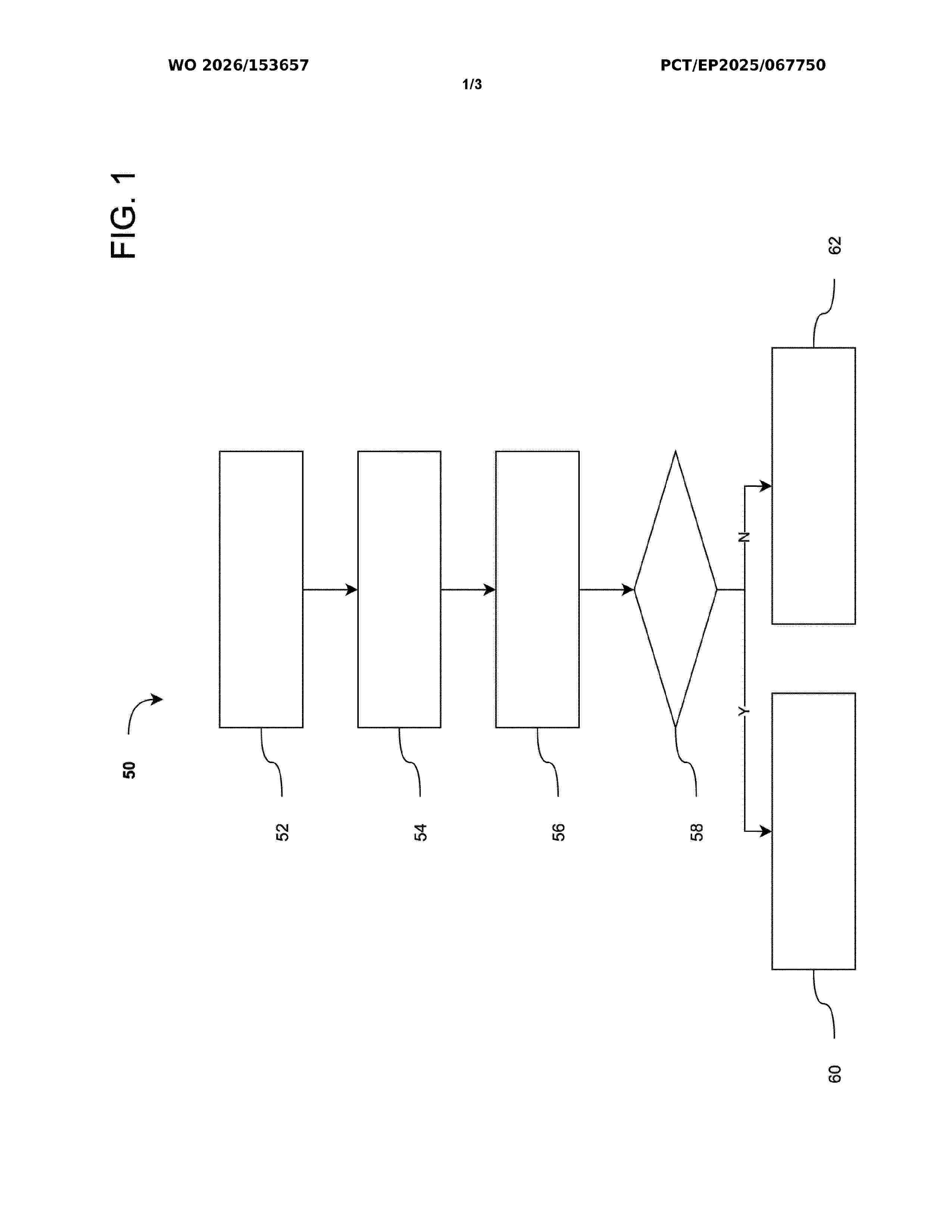
Resumen de: WO2026153657A1
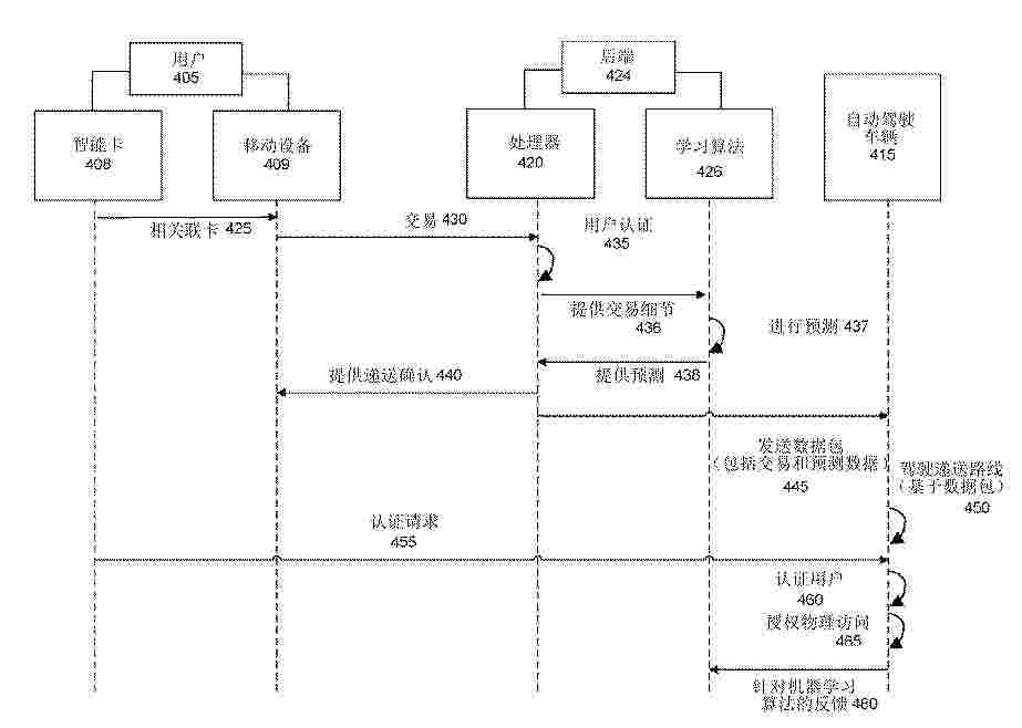
The present invention relates to a computer-implemented method (50) for enabling an automated action, comprising: providing a rule data set having enabling rules in at least one block of a blockchain (52), and retrieving the rule data set by means of a blockchain read-out device (54), characterized by evaluation of the rule data set by means of an agent device (56), the enabling rules and a machine learning method being taken into account for an enabling decision (58) for the automated action. The present invention further relates to a corresponding data processing arrangement and to a corresponding computer program product.
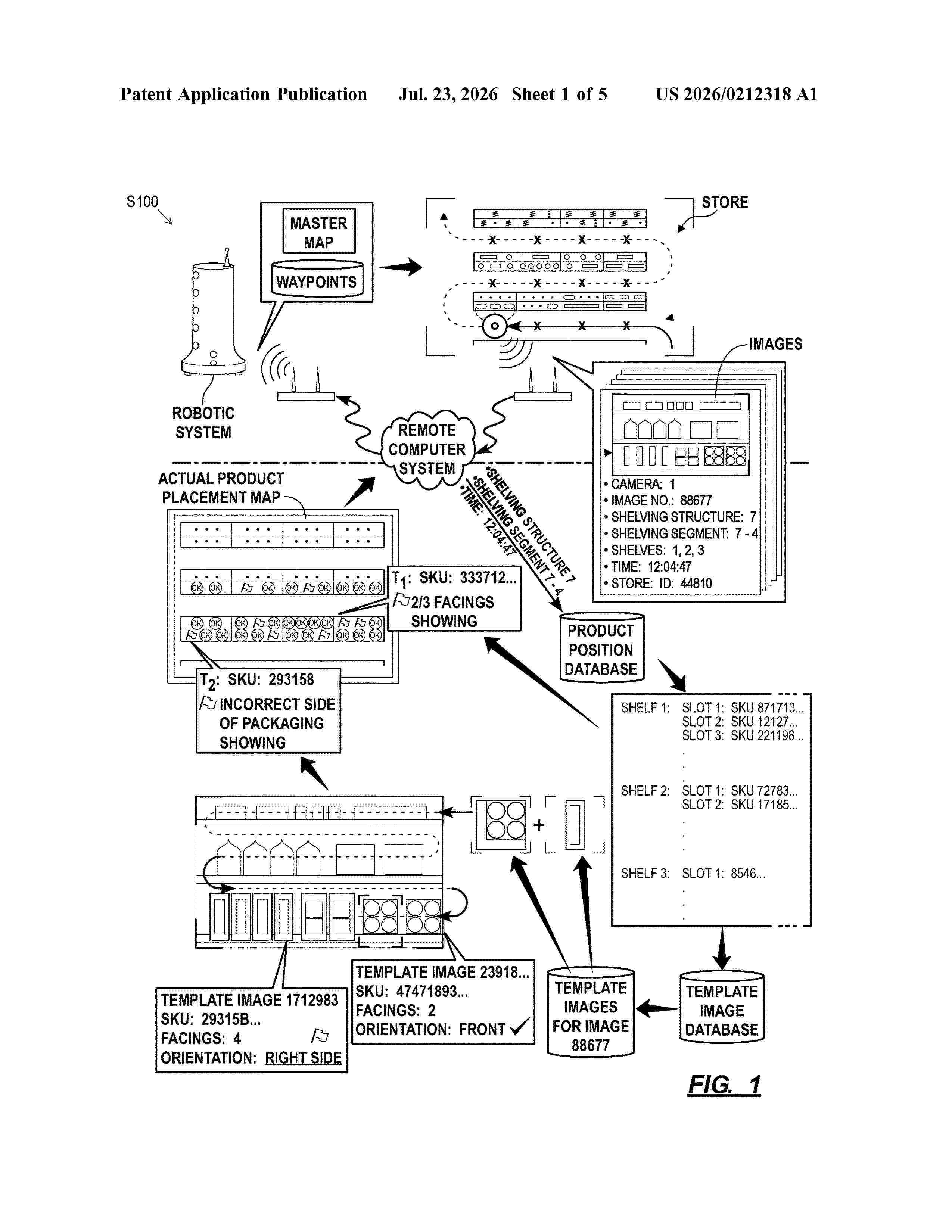
Resumen de: US20260212318A1
0000 A method includes: locating a first slot boundary around a first product unit, in an image of an inventory structure in a store, identifies as a first product type based on features detected in the image; extracting a first product identifier, from a first slot tag, detected in the image; based on correspondence between the first product identifier and product type, associating the first slot boundary with the first slot tag and extracting a first relative tag-boundary position of the first slot boundary and slot tag from the image; extracting a second product identifier from a second slot tag detected in the image; predicting a second slot boundary, assigned to a second product type corresponding to the second product identifier, in the image based on a second position of the second tag in the image and the first relative tag-boundary position.
Resumen de: US20260212640A1
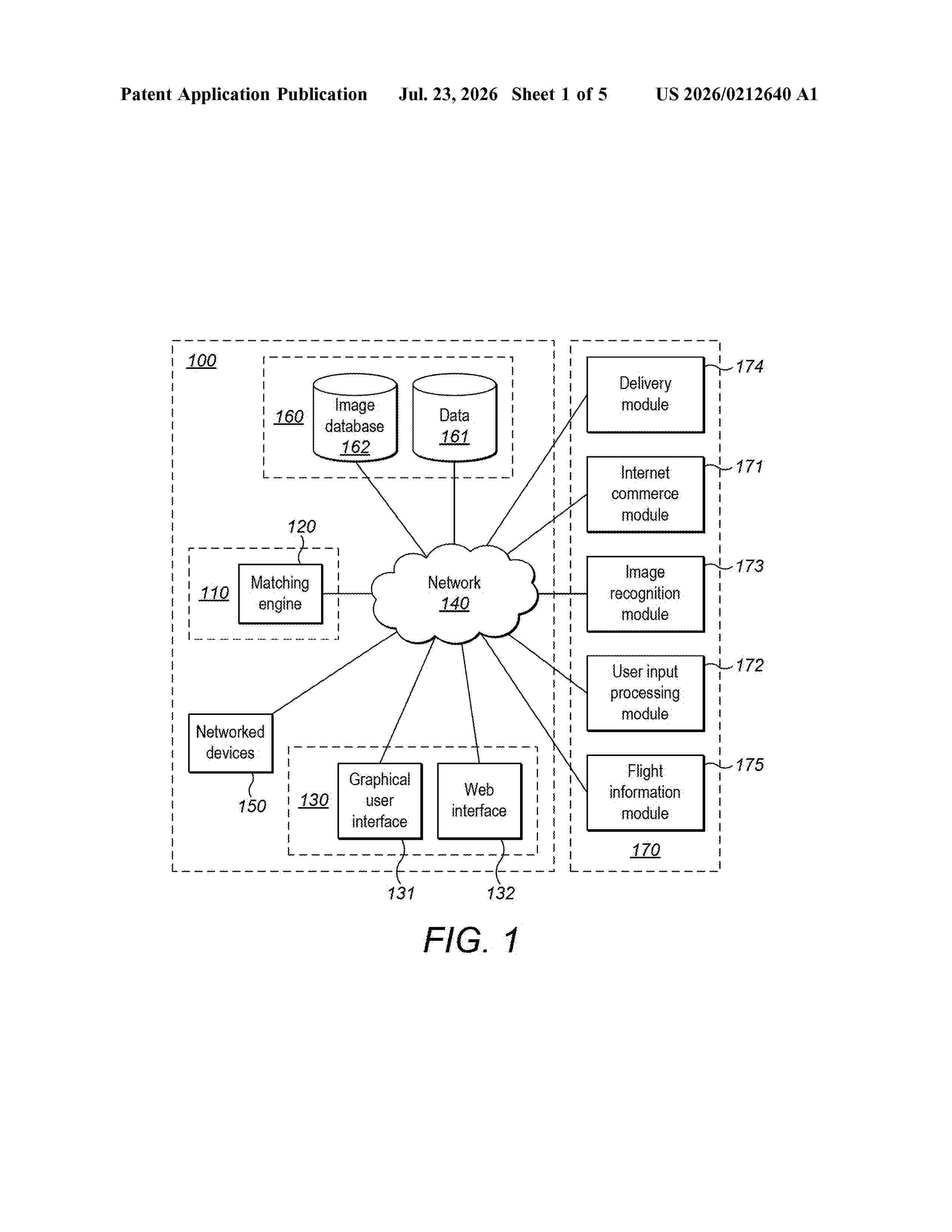
A system and method for managing lost items is described. The system comprises an application that receives information associated with one or more found items, which includes an image of each found item, and item-related information associated with a lost item. An image processing module identifies metadata associated with each found item based on the image of each found item and the received information associated with each found item. A matching engine determines a score for each found item based on a comparison between the item-related information for the lost item and the metadata associated with each found item.
Resumen de: US20260213959A1
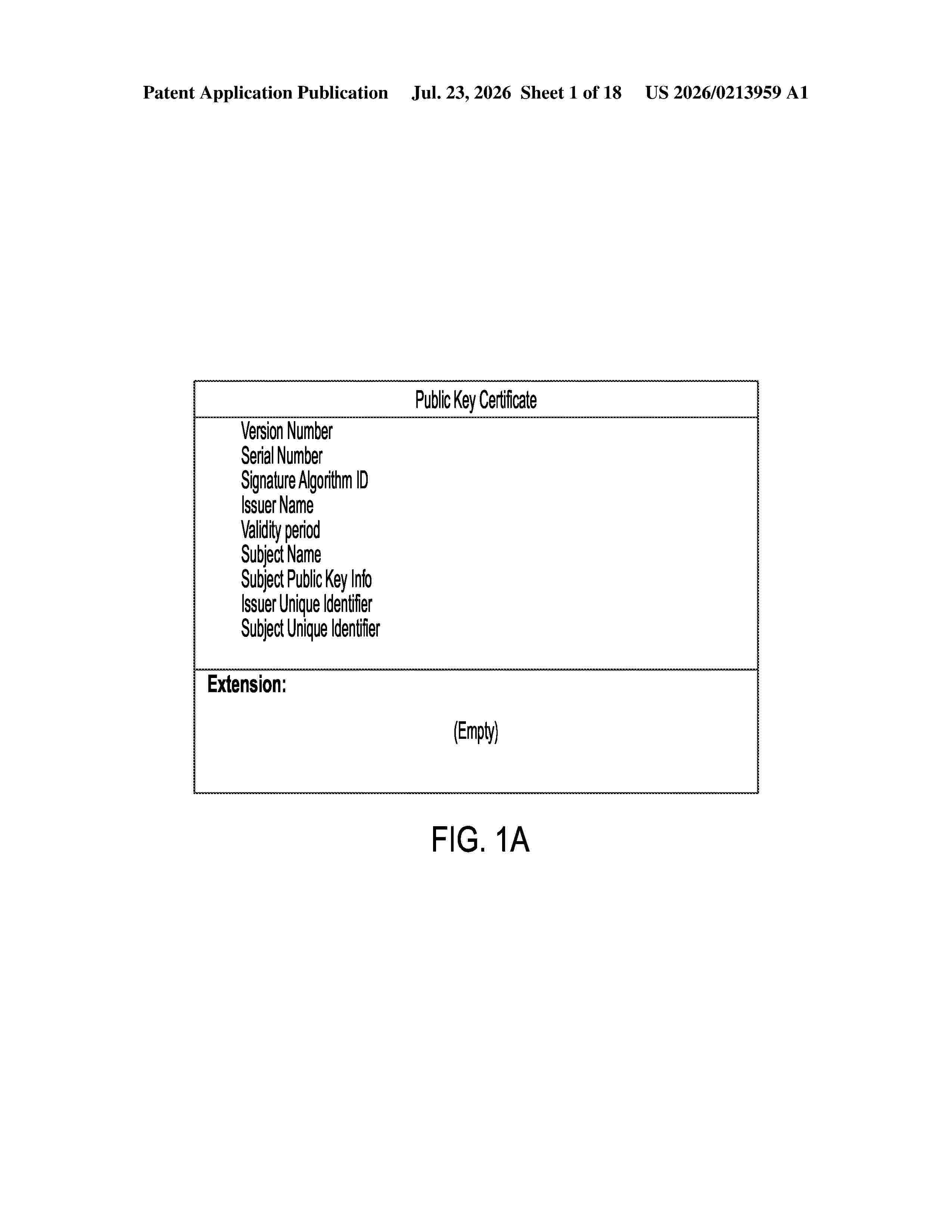
A method for sequential authentication based on chain of authentication using public key infrastructure (PKI) is provided. The method includes generating, by a user, a first private key and a first public key corresponding to each other; generating, by an nth service provider, an nth private key and an nth public key corresponding to each other; transmitting, from the user to the nth service provider, a level n key; verifying, by the nth service provider, the level n key; generating, by the nth service provider, a level (n+1) key by concatenating the level n key and the nth public key signed with the nth private key; and transmitting, by the nth service provider, the level (n+1) key to the user, where n is a natural number, and when n=1, the level 1 key is the first public key signed with the first private key.
Resumen de: AU2026205279A1
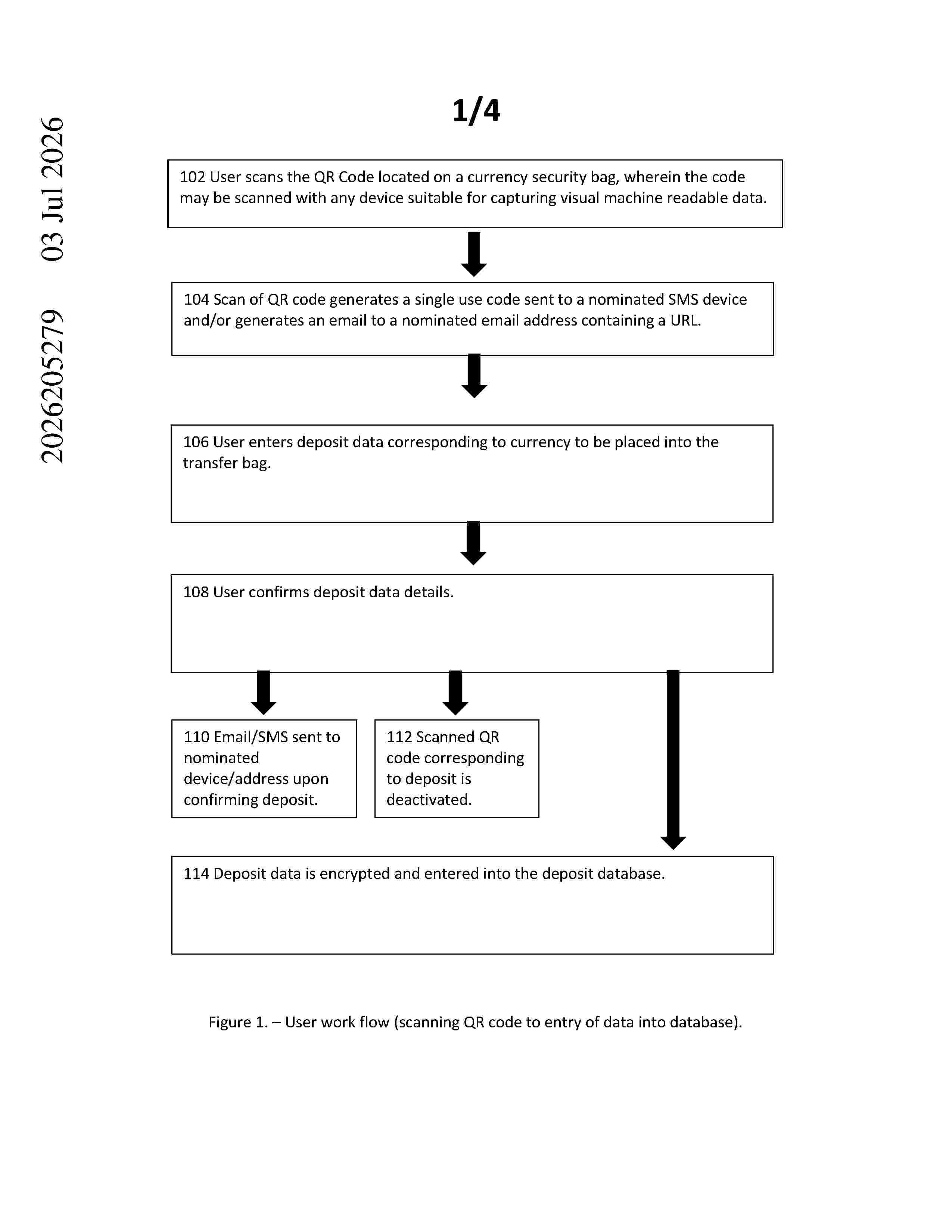
Abstract Described herein is a method, product and system for tracking currency transfer, said method comprising use of a currency security bag containing currency and a series of steps to securely monitor information corresponding to the security bag. The security bag allows for 5 a user to track the currency from a point of deposit until reaching a destination. Abstract ul b s t r a c t u l
Resumen de: AU2026205394A1
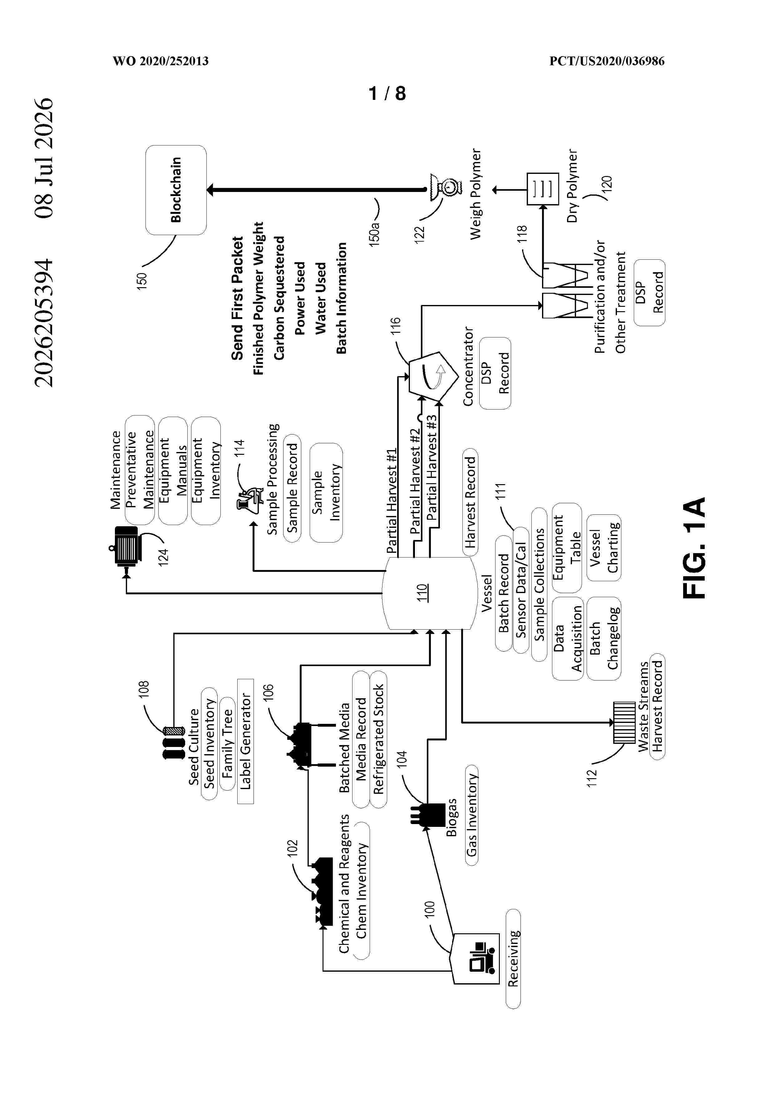
MARKED-UP COPY MARKED-UP COPY Systems and methods are disclosed for tracking, via a blockchain registry, carbon credits in goods produced from materials with sequestered carbon. Materials with sequestered carbon may be produced by reacting greenhouse gases with air and other reagents and catalysts (including biological organisms). Following production of a batch of material with sequestered carbon, a blockchain entry may be recorded with production details and details of carbon-credits earned during production. The carbon-sequestering material may later be converted into products, each of which may have a unique product identifier. A blockchain entry may be recorded with the unique product identifiers such that an owner of a unit of product can obtain, from the blockchain registry, a verified amount of carbon-credit associated with that unit. associated with that unit. ul u l
Resumen de: US20260212290A1
A system and method are disclosed for displaying a visualization of tasks to be performed across one or more time intervals. Embodiments include receiving two or more tasks from a task database comprising one or more attributes in a table format, the table having two or more rows and two or more columns, adding a column to each of the two or more tasks comprising the volume of tasks to be cumulatively performed during a time interval and adding a column to each of the two or more tasks comprising the cumulative volume due during the time interval. Embodiments also include displaying, on a graphical user interface, a visualization of the cumulative volume due and the cumulative planned curve representing the volume of tasks to be performed across one or more time intervals.
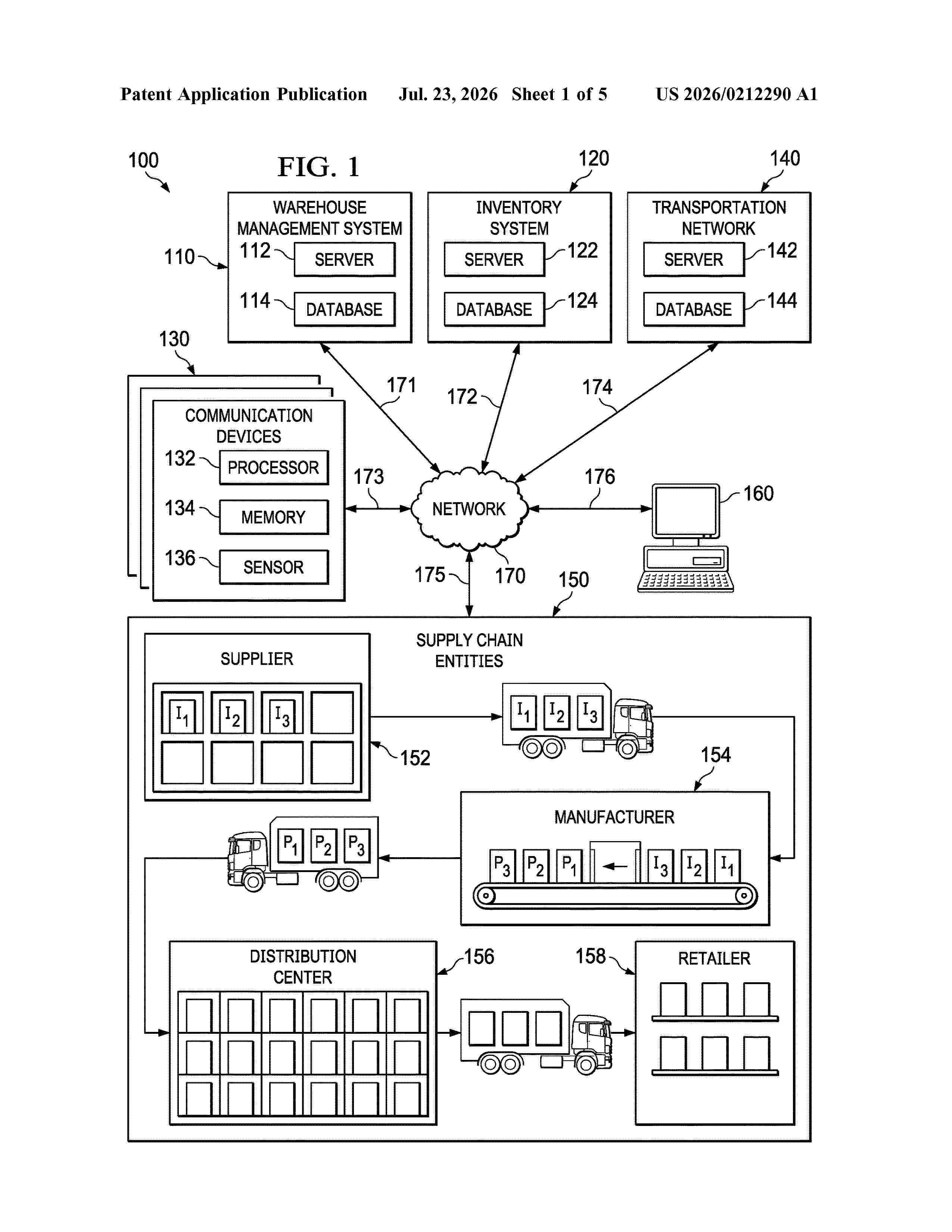
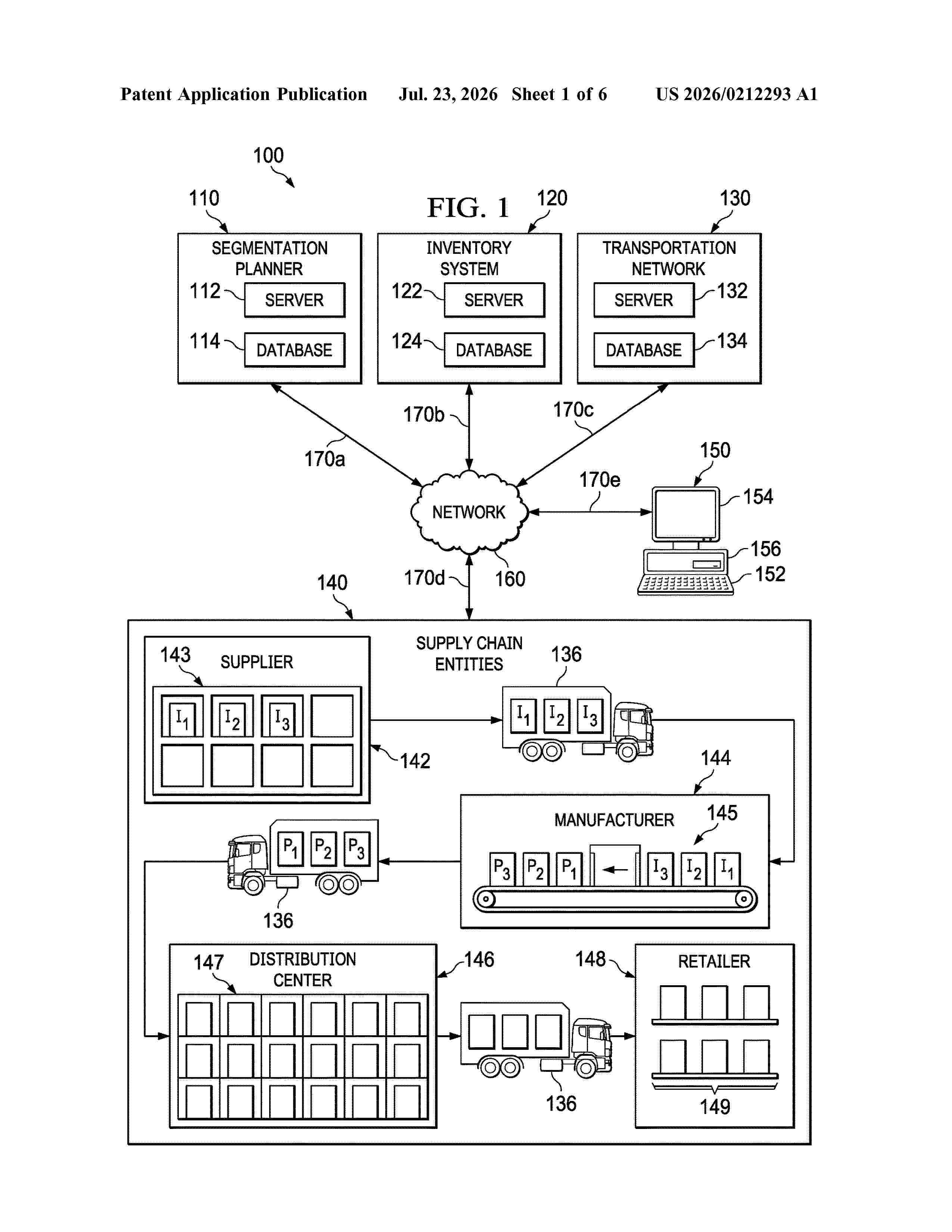
Resumen de: US20260212293A1
A system and method of autonomous multi-dimensional segmentation for a supply chain network. Embodiments include a supply chain network of one or more supply chain entities, a segmentation planner having a computer and memory, the segmentation planner configured to access input data relating to one or more supply chain entities, discover one or more features related to the input data, pre-process the input data and features, perform multi-dimension segmentation on the input data, compute the importance of the one or more features, generate a multi-dimension segmentation visualization, assign policy parameters to the multi-dimension segmentation performed on the input data.
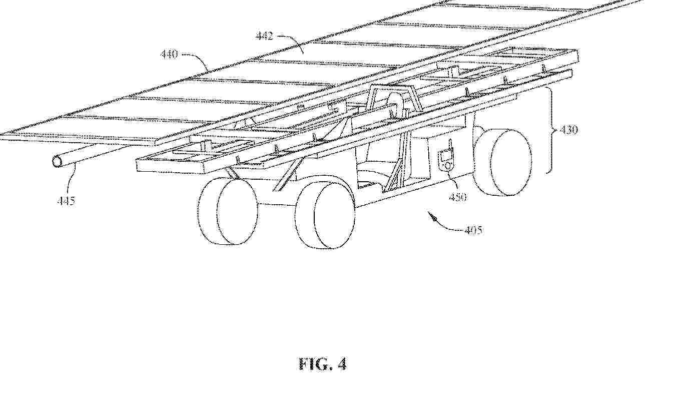
Resumen de: AU2024415851A1
Solar panels may have manufacturing defects that warrant a recall by solar panel manufacturers. Given the large quantity of solar panels in a solar farm, it is challenging to identify and track those panels affected by the recall. The present invention describes system and method embodiments for solar panel tracking for the convenience of solar panel service or replacement. Panel identifiers of solar panels in a solar table installed on an installation site of a solar farm are scanned such that the panel identifiers of the solar panels may be associated with the geographical information at the installation site. A geographical database for solar panels may be created and updated, with each panel having an entry of panel information and geographical information. When a recall is issued, involved solar panels in the solar farm may be quickly and accurately identified using the geographical database.
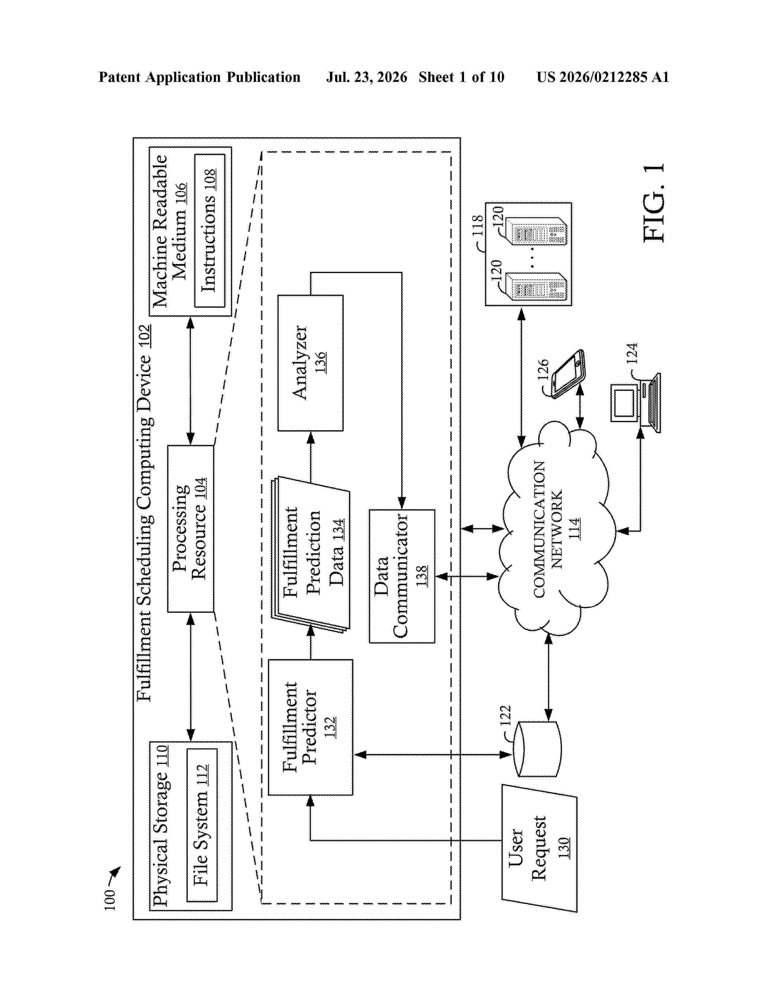
Resumen de: US20260212285A1
0000 Example implementations relate to predicting fulfillment times for user requests. In an example, a user request including item data, a fulfillment location, and a provisional fulfillment time is received by a system. The system requests, via a fulfillment predictor, fulfillment data for the fulfillment location. The fulfillment data including at least a fulfillment order for the user request and ongoing fulfillment orders for the user request. The system, in response to receiving the fulfillment data, determines, by the fulfillment predictor, a predicted fulfillment time for the user request. The system determines whether a difference between the provisional fulfillment time and the predicted fulfillment time is within a fulfillment time threshold and, in accordance with a determination that the difference between the provisional fulfillment time and the predicted fulfillment time is outside the fulfillment time threshold, transmits the predicted fulfillment time to at least one computing device.
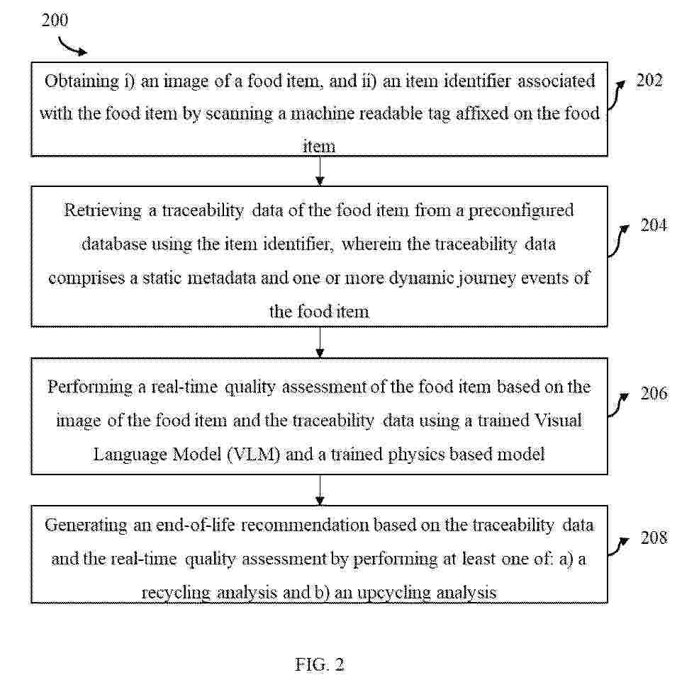
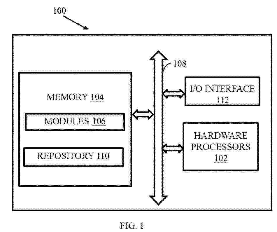
Resumen de: EP4779541A1
Global food systems face a paradox: rising demand and widespread hunger coexist with massive food waste, especially fresh produce. Short shelf life, poor forecasting, and lack of transparency lead to unnecessary disposal, contributing to greenhouse gas emissions and sustainability challenges. Consumers also lack reliable information on freshness and nutritional value, further worsening waste. Hence, embodiments of present disclosure provide a method and system for traceability, quality assessment and end of life recommendations of a food item. Initially an image of the food item is captured and a machine-readable tag on the food item is scanned to retrieve traceability data. Then, using trained Visual Language and physics-based models, visual and biochemical features are analyzed to compute ripeness, shelf life, and freshness scores. Further, usage recommendations and end-of-life options are recommended, including recycling guidance for packaging and upcycling opportunities for leftovers. This integrated approach ensures transparency, optimizes consumption, and supports sustainability.
Resumen de: EP4779543A1
A purchase order is a commercial document issued by a buyer. Conventional methods fails to categorize the purchase orders accurately by using item description alone. The present disclosure receives purchase orders associated with an organization and normalizes by expanding a plurality of acronyms using a large language model. A first category pertaining to normalized purchase orders is determined. A second category of normalized item descriptions are further obtained by selecting a local guided categorizer or a global guided categorizer based on the categorizer selection flag. Further, a final category is obtained based on the first category and the second category and a dynamic threshold value. Finally, the plurality of item descriptions of the plurality purchase orders are grouped based on an associated final category and vector embeddings using a grouping technique. The grouped plurality of item descriptions are updated in training dataset pertaining to a local categorizer.
Resumen de: EP4779539A1
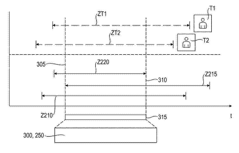
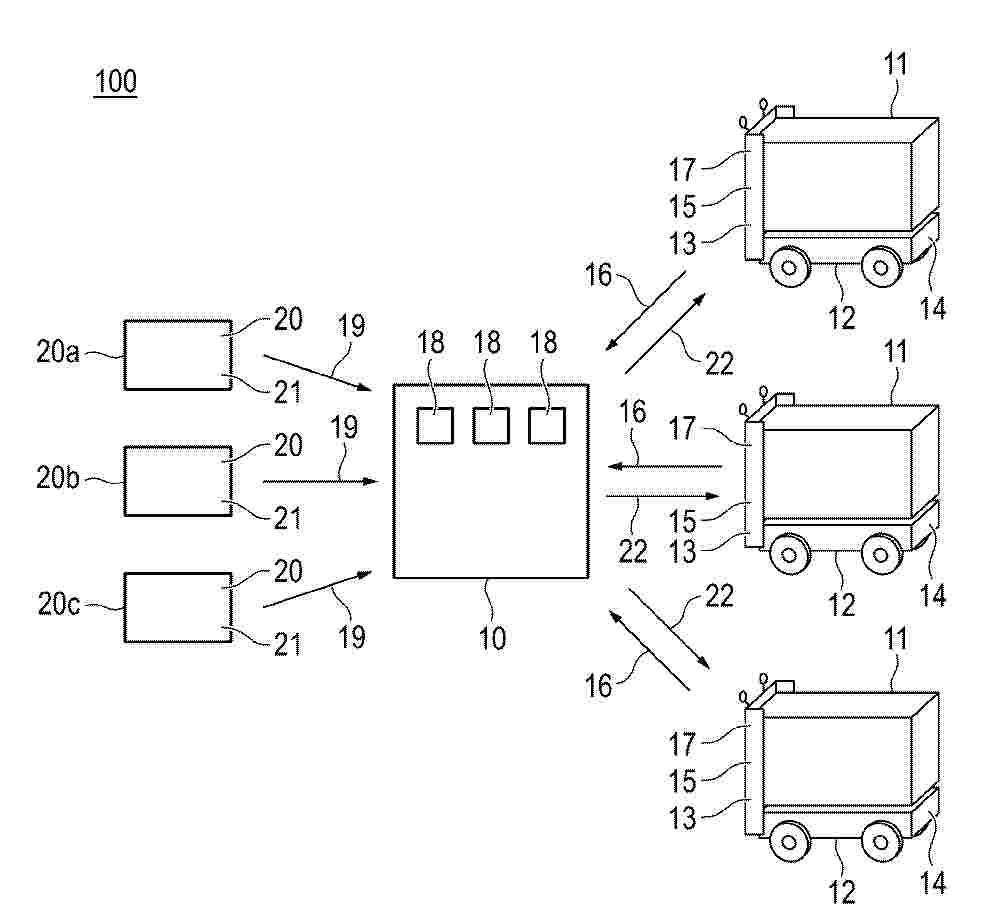
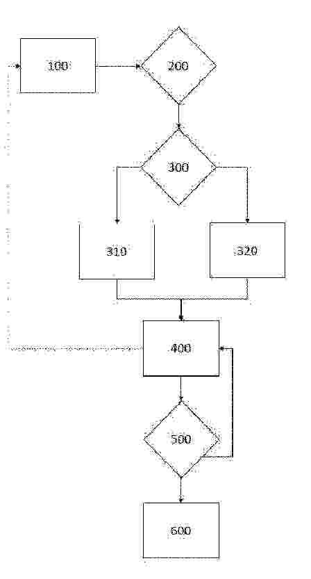
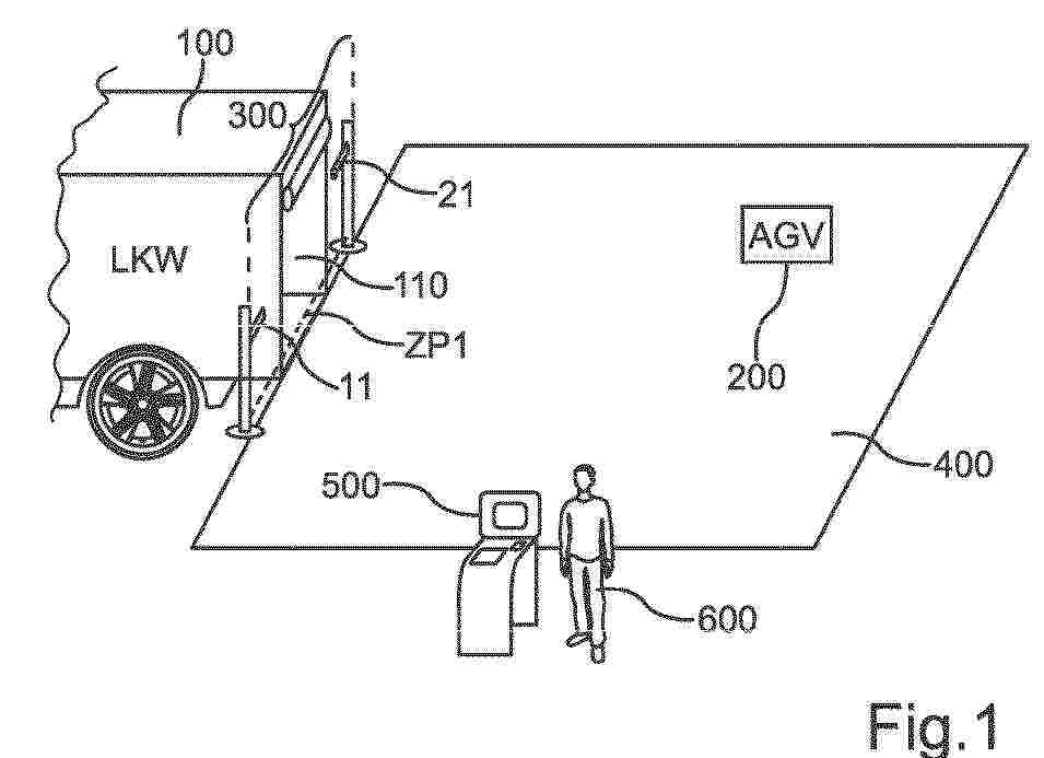
0001 Die vorliegende Erfindung betrifft ein computer-implementiertes Verfahren (100) zum Erstellen eines Wartungsablaufs (240) für eine landwirtschaftliche Arbeitsmaschine (200), wobei eine Servicestation (S) zur Durchführung von Wartungsschritten an der landwirtschaftlichen Arbeitsmaschine (200) bereitsteht, das Verfahren (100) umfassend: Erfassen einer Wartungsmeldung (235) der landwirtschaftlichen Arbeitsmaschine (200), wobei die Wartungsmeldung (235) eine Maschinenkonfiguration umfasst; Ermitteln einer Teileliste (245) basierend auf der Wartungsmeldung (235), wobei die Teileliste (245) die für die Wartung benötigten Teile (250) umfasst; und Erstellen eines Wartungsablaufs (240), indem ein Wartungszeitfenster (300) der Servicestation (S) basierend auf einem Abgleich der benötigten Teile (250) mit in der Servicestation (S) vorhandenen Teilen (210, 215, 220) bestimmt wird.
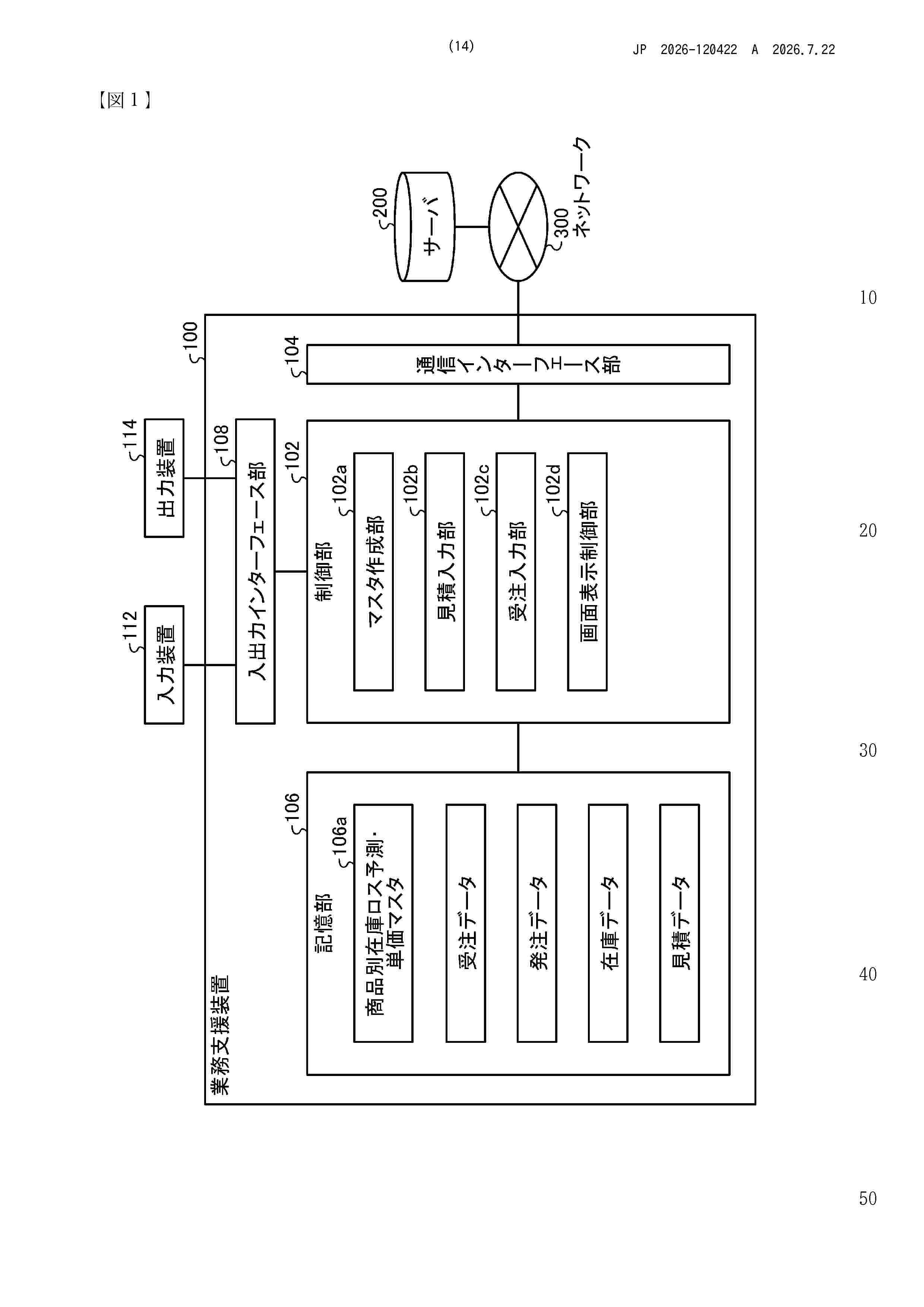
Resumen de: JP2026120422A
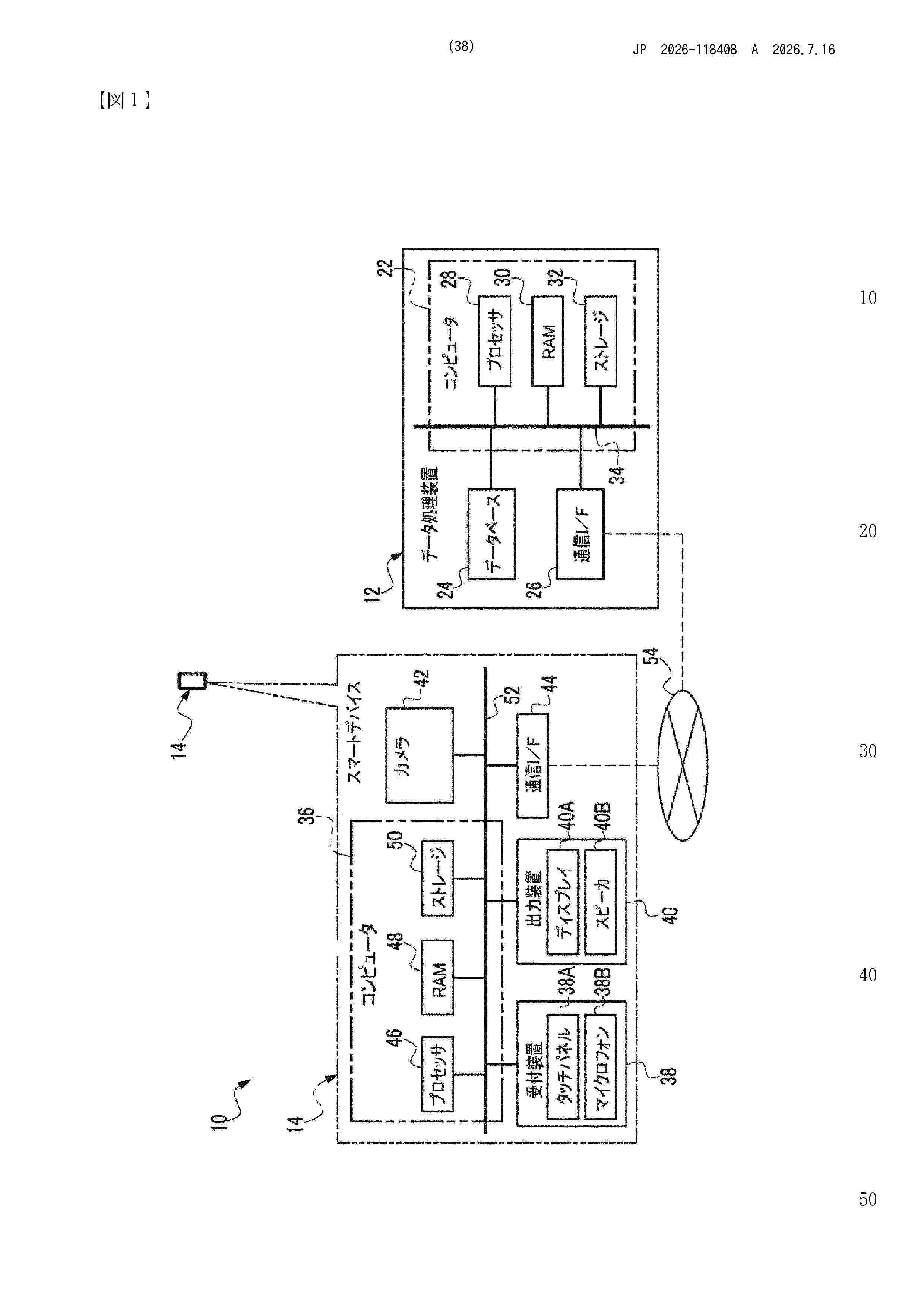
【課題】在庫ロスを防ぐための単価マスタを作成することで、在庫ロスを防止すること。【解決手段】マスタ作成部102aは、例えば、モニタ114に表示される単価マスタ設定画面上でのオペレータの操作に応じて、指定される基準日、出荷期限到来日、有効期限到来日の抽出条件に基づいて、前記在庫データ、前記受注データ、及び発注データを参照して、商品を抽出し、在庫データの現在庫数に対する受払予定を加減算して、在庫数を算出し、商品候補として、抽出した商品、出荷期限、有効期限、算出した在庫数のレコードを表示し、商品候補からオペレータにより商品が選択され、オペレータにより適用開始日、適用終了日、単価が指定されると、選択された商品、指定された、適用開始日、適用終了日、単価のレコードを、単価マスタ106aに追加して更新する。【選択図】図1
Resumen de: JP2024131458A
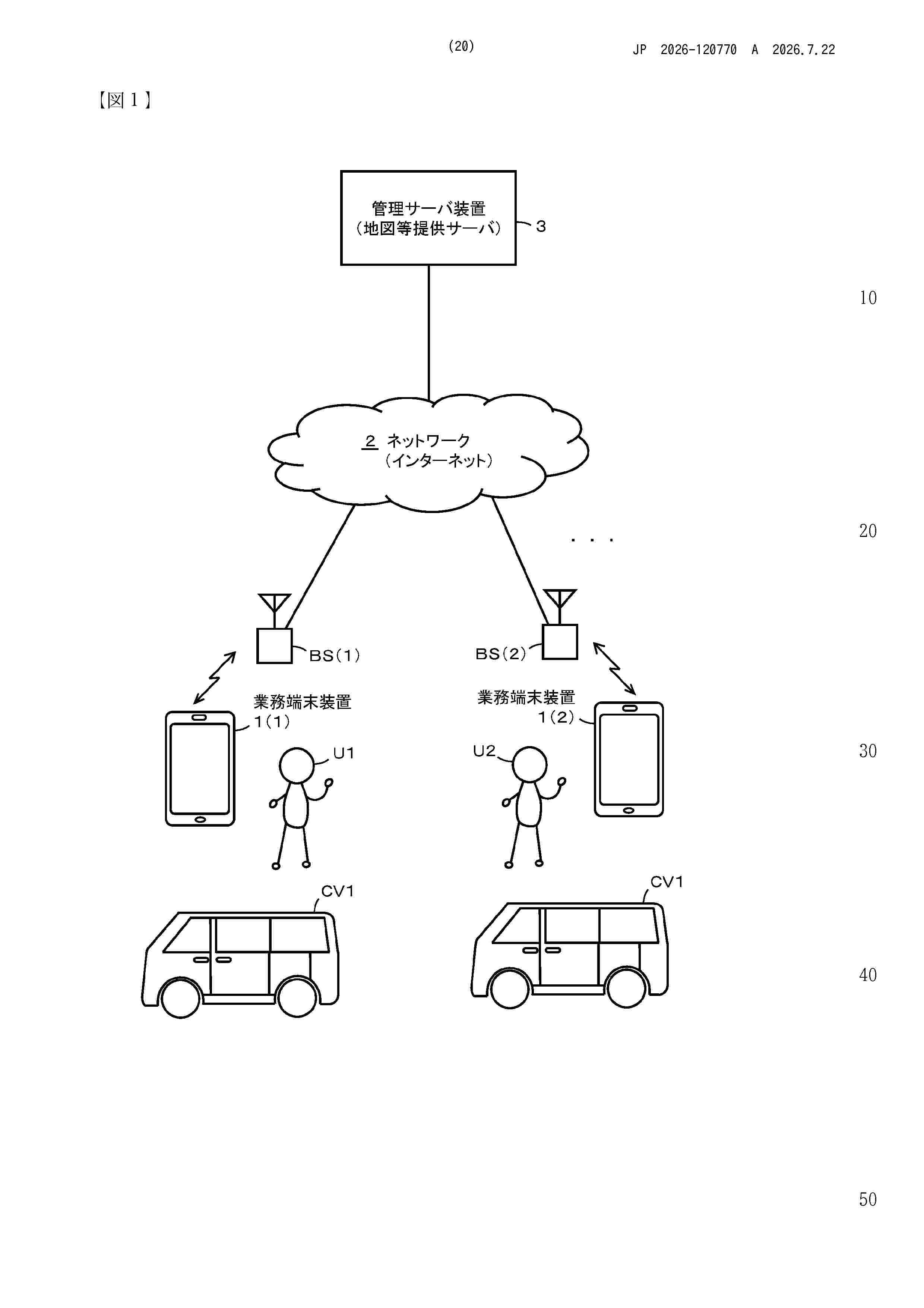
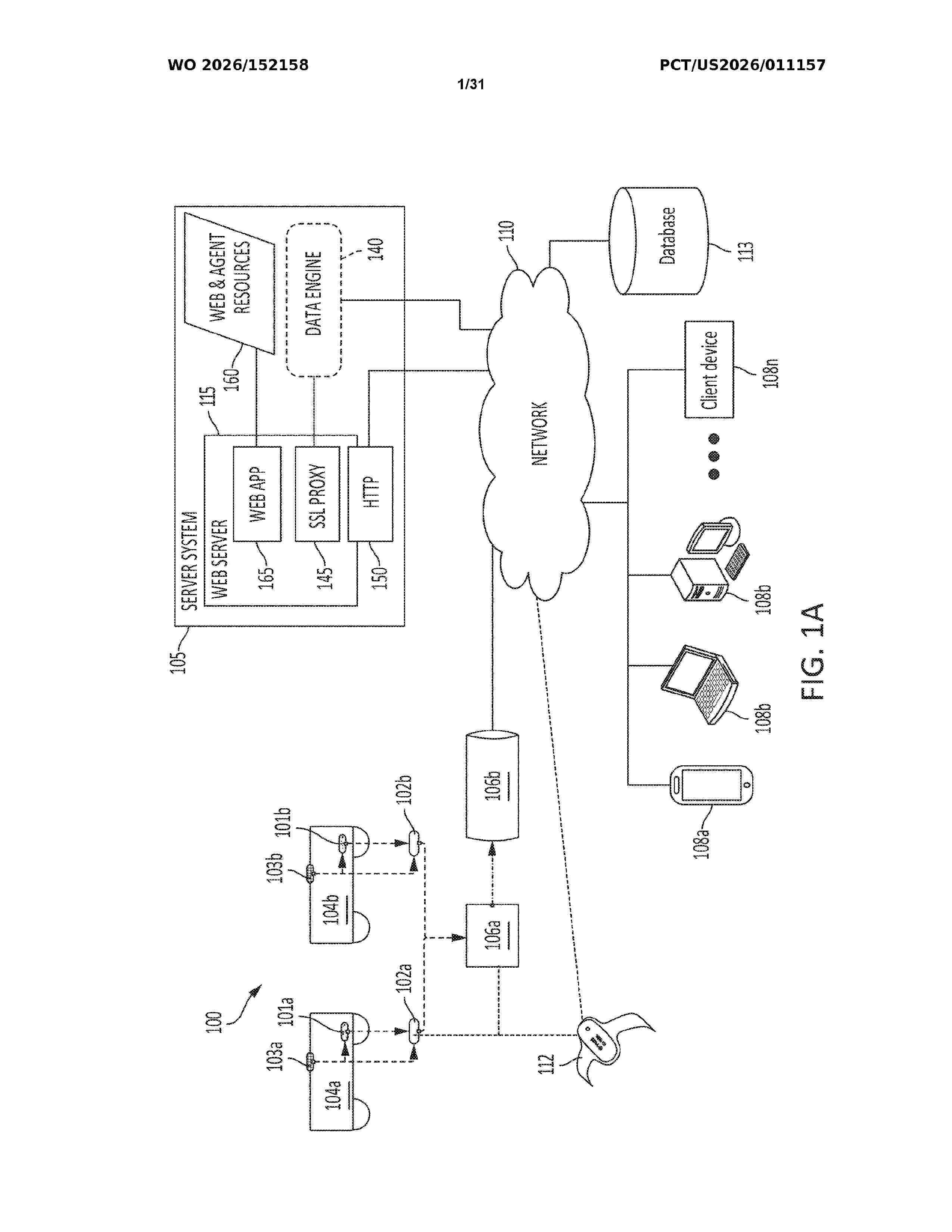
To provide a business terminal device, a health checking program before starting a work and a delivery business system which allow a person who performs a transport business to implement a health check for himself/herself in appropriate timing without being conscious before start-up, and record its result to be accumulated.SOLUTION: In a delivery business system, a business terminal device 1 held by a user who performs a delivery business during a work, mutually communicates with a management server device through a network, and comprises a health check unit 151 which discriminates, when the business application software is started, whether it is a start of the work, accepts input of health management information before the start of the work of the user through a closes range radio communication antenna 110A, a close range radio communication unit 110, and a touch panel 120 when it is discriminated that it is a start of the work, and records the accepted health management information in a health check file 107.SELECTED DRAWING: Figure 2
Resumen de: EP4779933A1
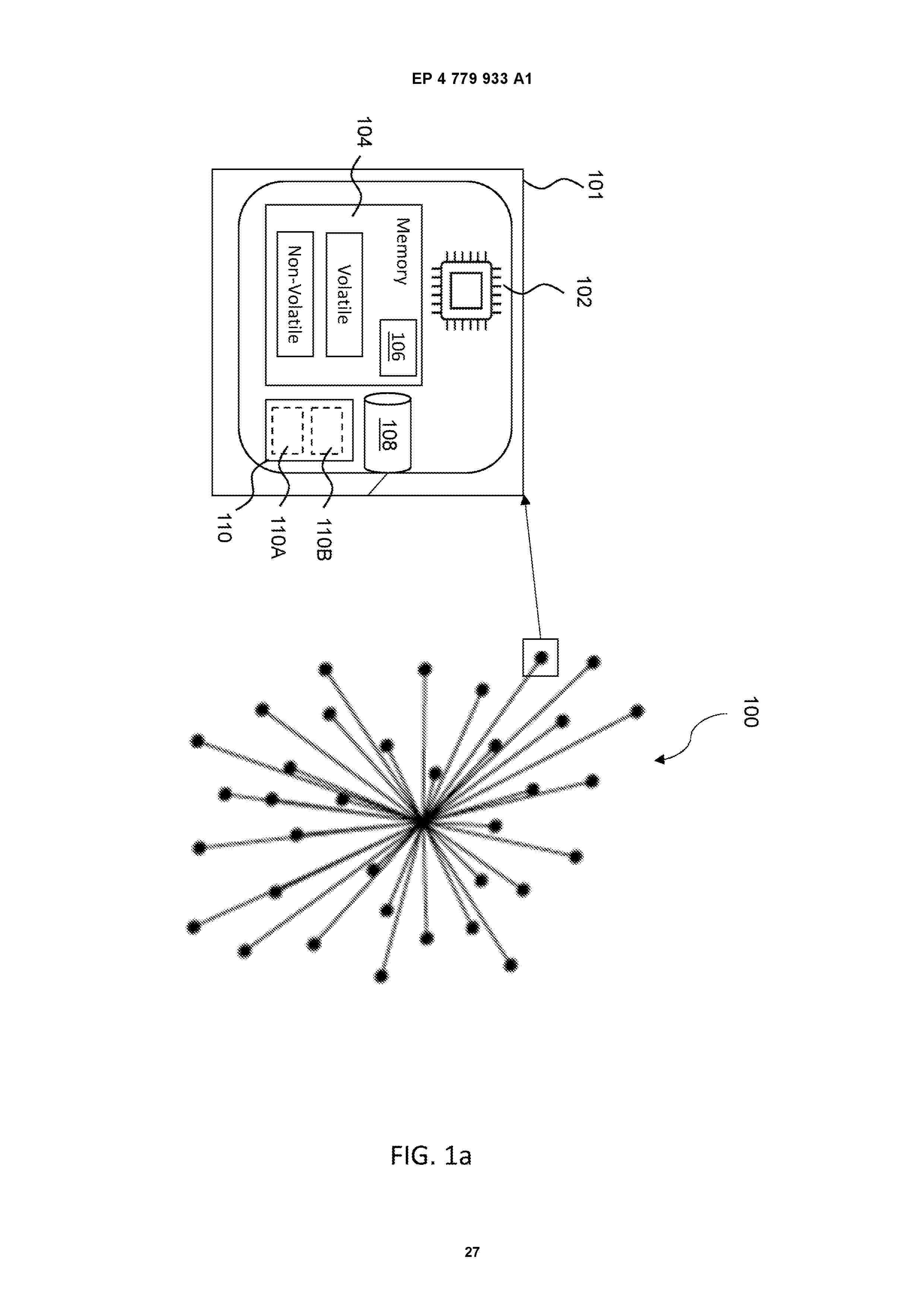
An apparatus for producing a chemical product associated with a chemical product passport, the apparatus comprising:a collector configured to collect recyclate content data and/or bio-based content data associated with the chemical product, wherein the chemical product comprises a physical identifier;an assignor configured to assign the physical identifier to a decentral identifier for generating the chemical product passport associated with the produced chemical product;a chemical product passport generator configured to generate the chemical product passport by receiving a request to provide at least the decentral identifier associated with recyclate content data and/or bio-based content data of at least the chemical product and in response to the request, generating the chemical product passport including the decentral identifier and data related to the recyclate content data and/or bio-based content data of the chemical product.
Resumen de: EP4482077A1
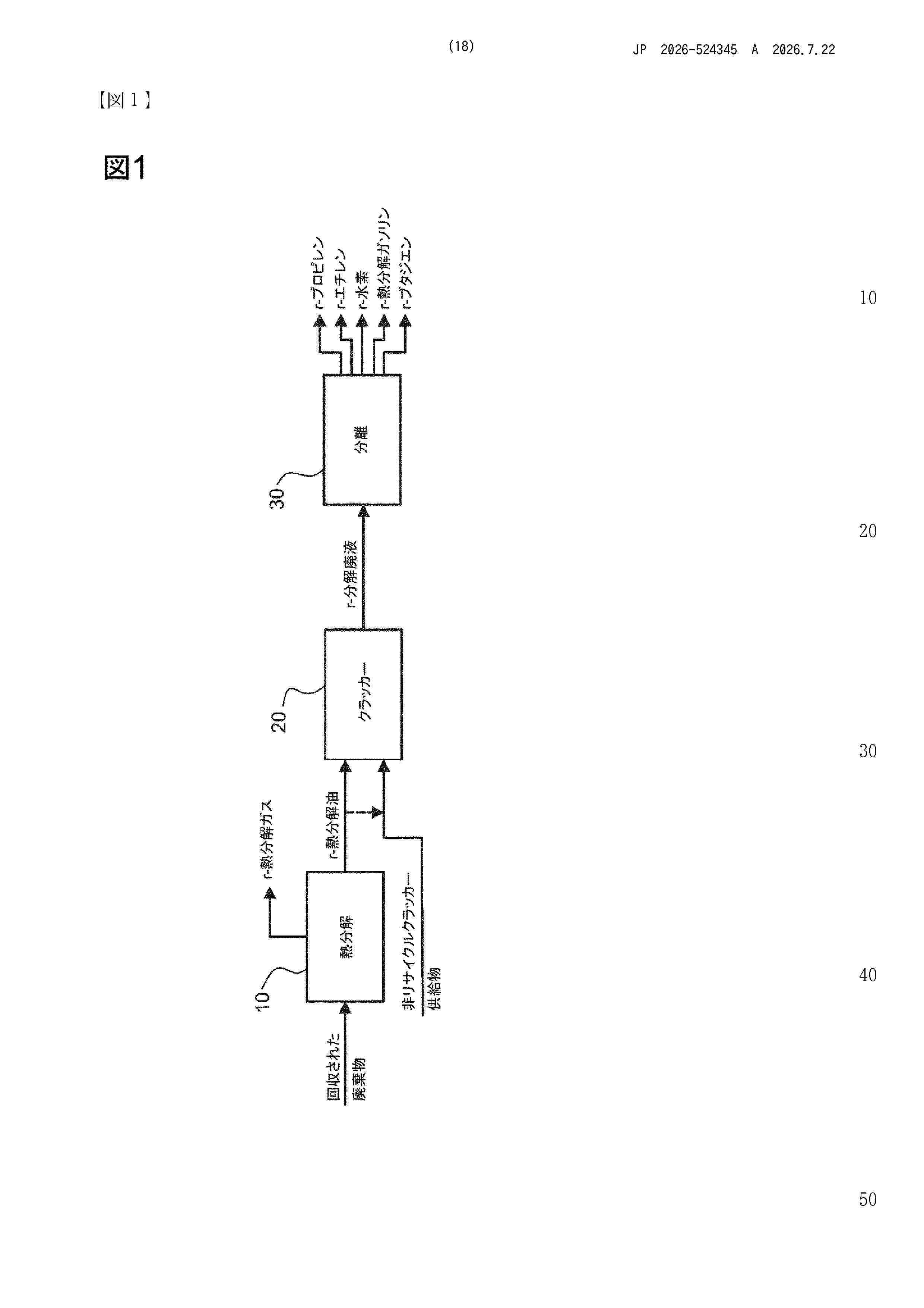
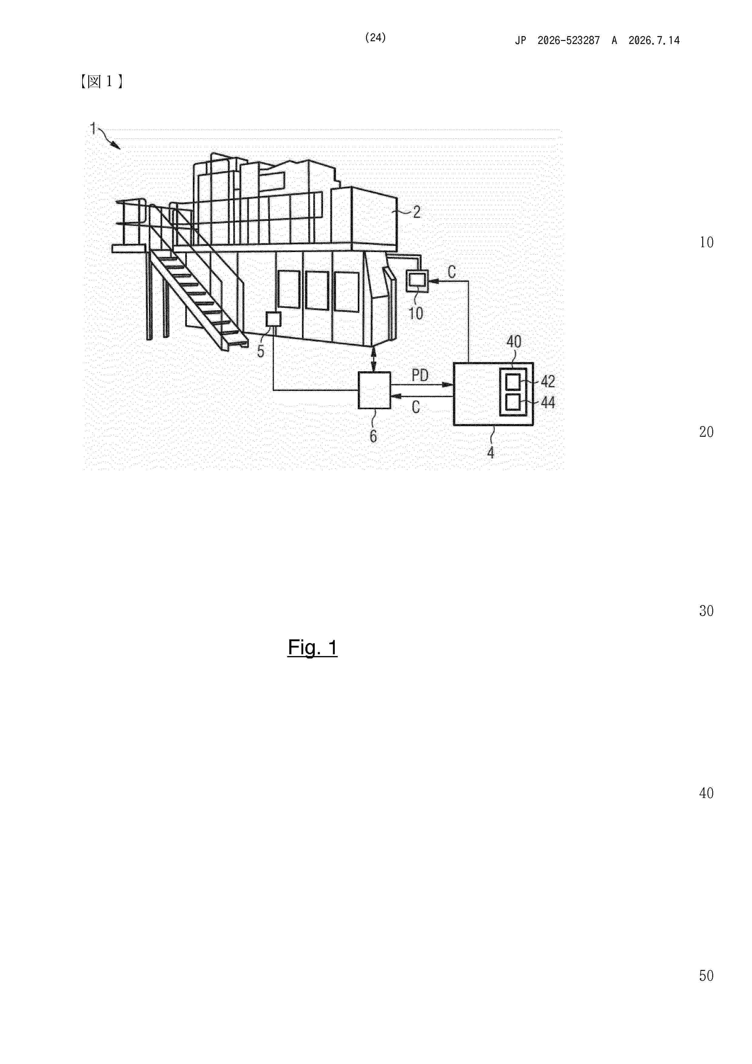
0001 Disclosed is a computer-implemented method for controlling production of a product in a production facility using one or more input materials, in particular for the production of a chemical product, wherein at least one of the input materials is a waste-derived material which may be provided from a source location to a target location of the production facility and wherein the source location and the target location may comprise two different waste-related technical requirements for the use of waste-derived materials for the production of a product, and wherein the method comprises the following steps: - providing a digital representation of the waste-related technical requirements for different source locations and target locations, wherein the digital representation includes the waste-related technical requirements as a rule-based model or set of rules, based on waste material categories being processed using material attributes for classifying a waste-derived material into at least one waste material category, and wherein it is distinguished between attested material attributes and associated material attributes; - evaluating at least one rule of the set of rules or the rule-based model relating to at least one waste material category for an underlying source location and for the target location, in particular regarding an attested material attribute for the waste-derived material; - generating control data for the production of the product, dependent on the result
Resumen de: US2025315882A1
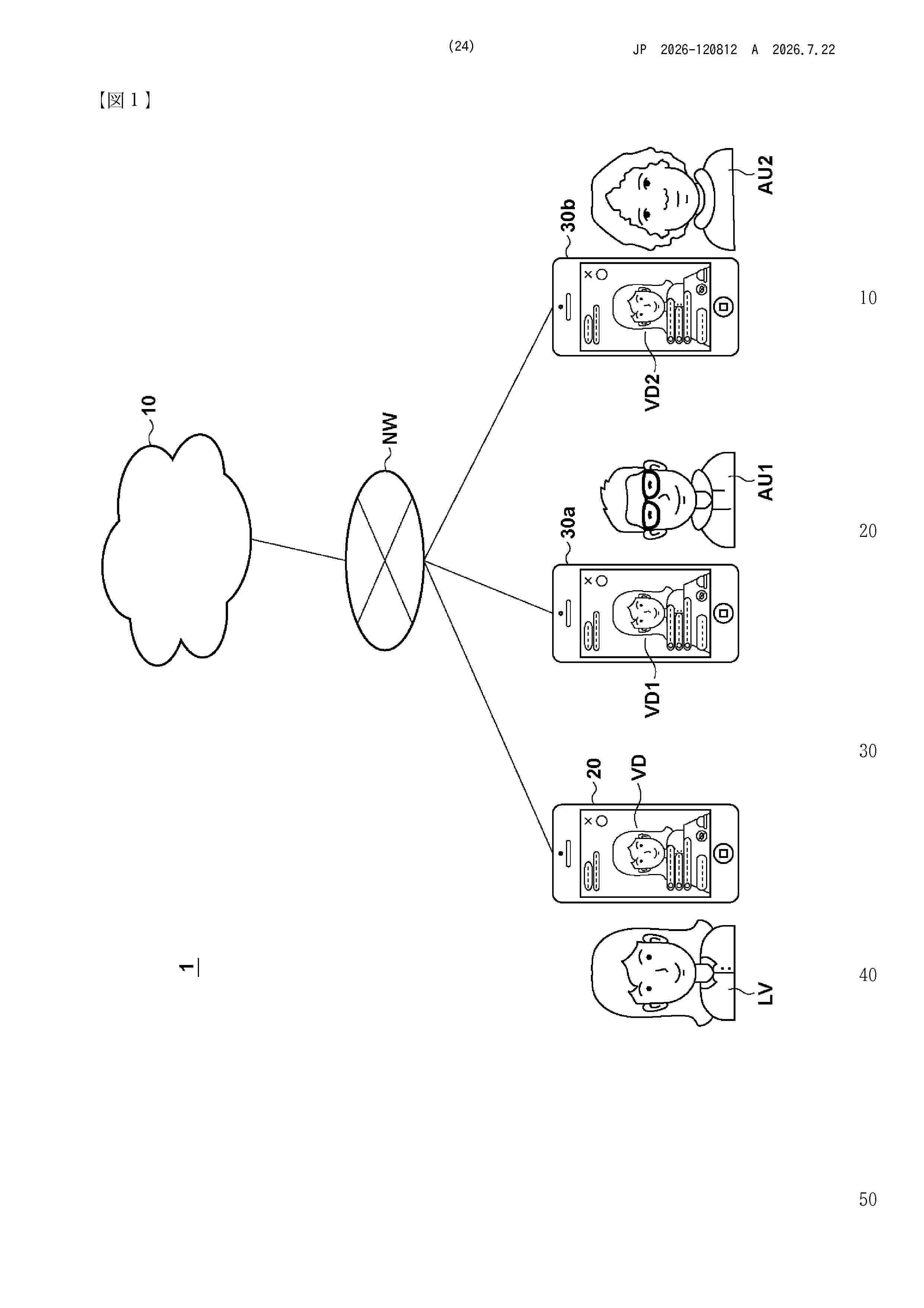
0000 The present disclosure relates to a terminal and a method for order management. The method includes: displaying an object associated with a post on a website supported by a first server on a user terminal of a first user; detecting the first user to have selected the object; transmitting a purchase comment from a second user and related to the post to a second server, wherein the first server is different from the second server.
Resumen de: EP4779515A1
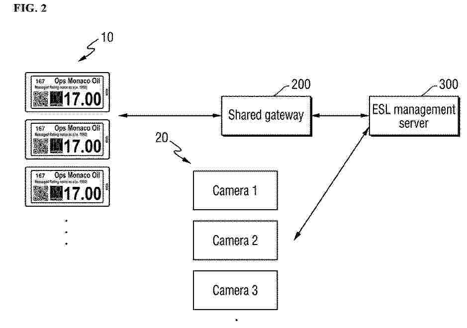
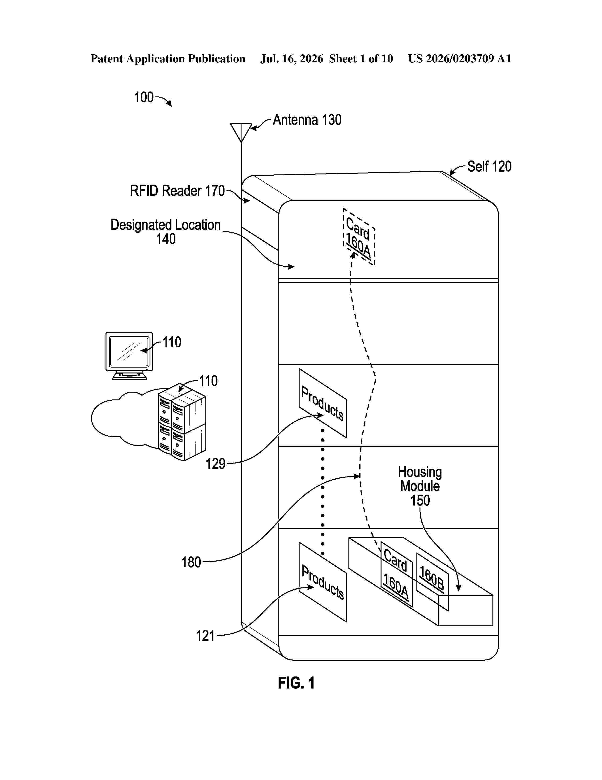
0001 According to one embodiment, an electronic shelf label recognition system includes a plurality of electronic shelf labels disposed on a shelf on which a plurality of products are displayed and corresponding respectively to the plurality of products, a plurality of cameras configured to capture the plurality of electronic shelf labels, and an electronic shelf label management server configured to manage the plurality of electronic shelf labels, recognize the plurality of electronic shelf labels captured by the plurality of cameras, and manage location information corresponding to the recognized plurality of electronic shelf labels.
Resumen de: US2025086584A1
An inventory management device, system, and method that can be configured to increase radio frequency identification (RFID) read accuracy and diversity in warehouse-based applications and in other inventory management scenarios. In one implementation, the inventory management device comprises a transportable frame that at least partially surrounds a housing, the transportable frame having a motor attachment surface. The housing includes a radio frequency identification (RFID) interrogator and an RFID antenna. In some implementations, there is a second RFID antenna located in the housing, and the first RFID antenna is orthogonally offset from the second RFID antenna.
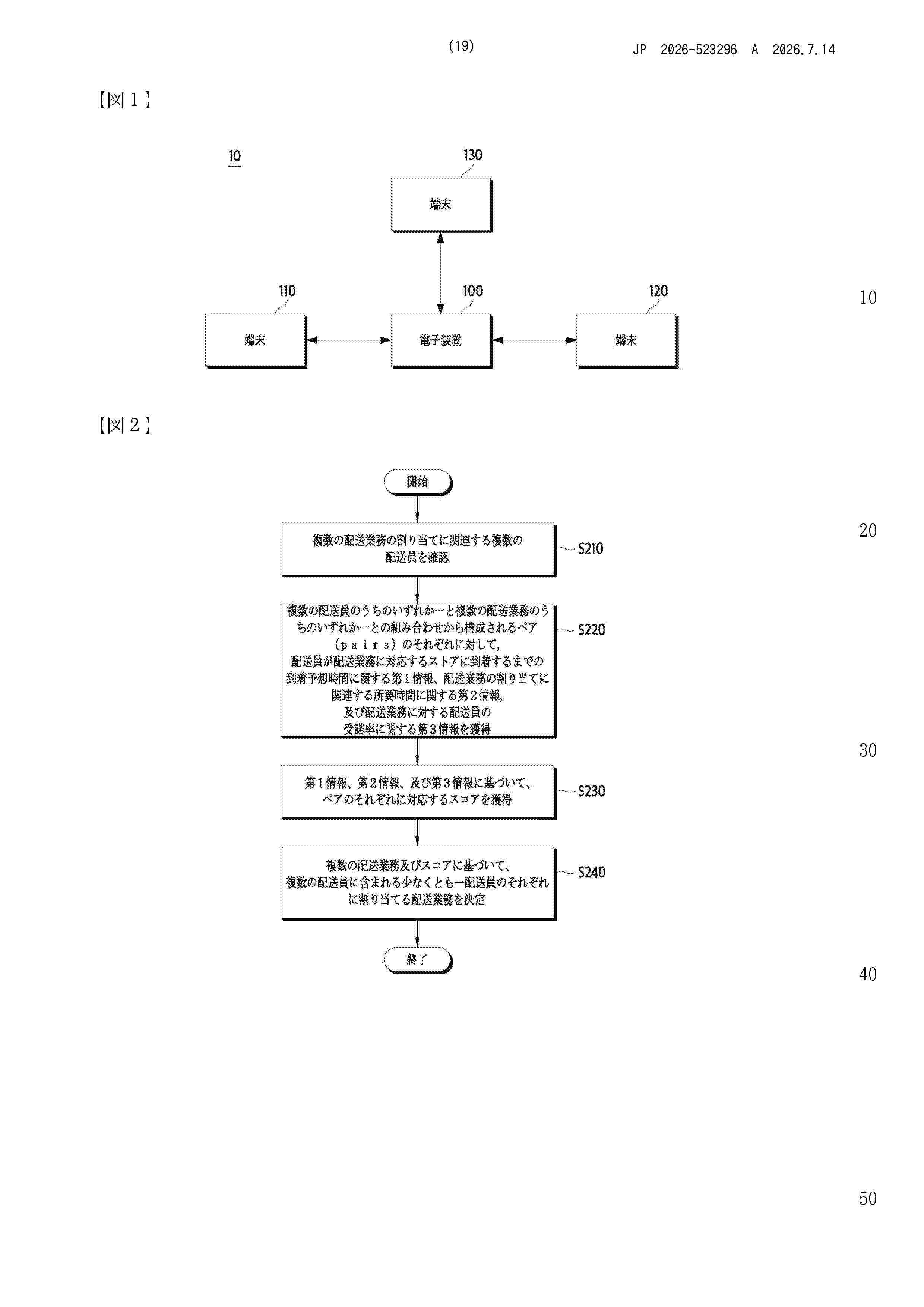
Resumen de: WO2025037665A1
An electronic device for optimizing allocation of a delivery order, and a method therefor are disclosed. The delivery order allocation optimization method according to the present disclosure may comprise the steps of: identifying a first delivery order that is unallocated; identifying a plurality of delivery workers that can process a delivery order; acquiring information about an additional delivery order; generating, on the basis of information about the first delivery order, the information about the additional delivery order, and information about the plurality of delivery workers, a plurality of allocation plans for allocating a target delivery order set that should be processed to the plurality of delivery workers; calculating a predicted cost and/or a predicted gain according to each of the plurality of allocation plans; and selecting an optimal allocation plan on the basis of the predicted cost and/or the predicted gain.
Resumen de: EP4482081A1
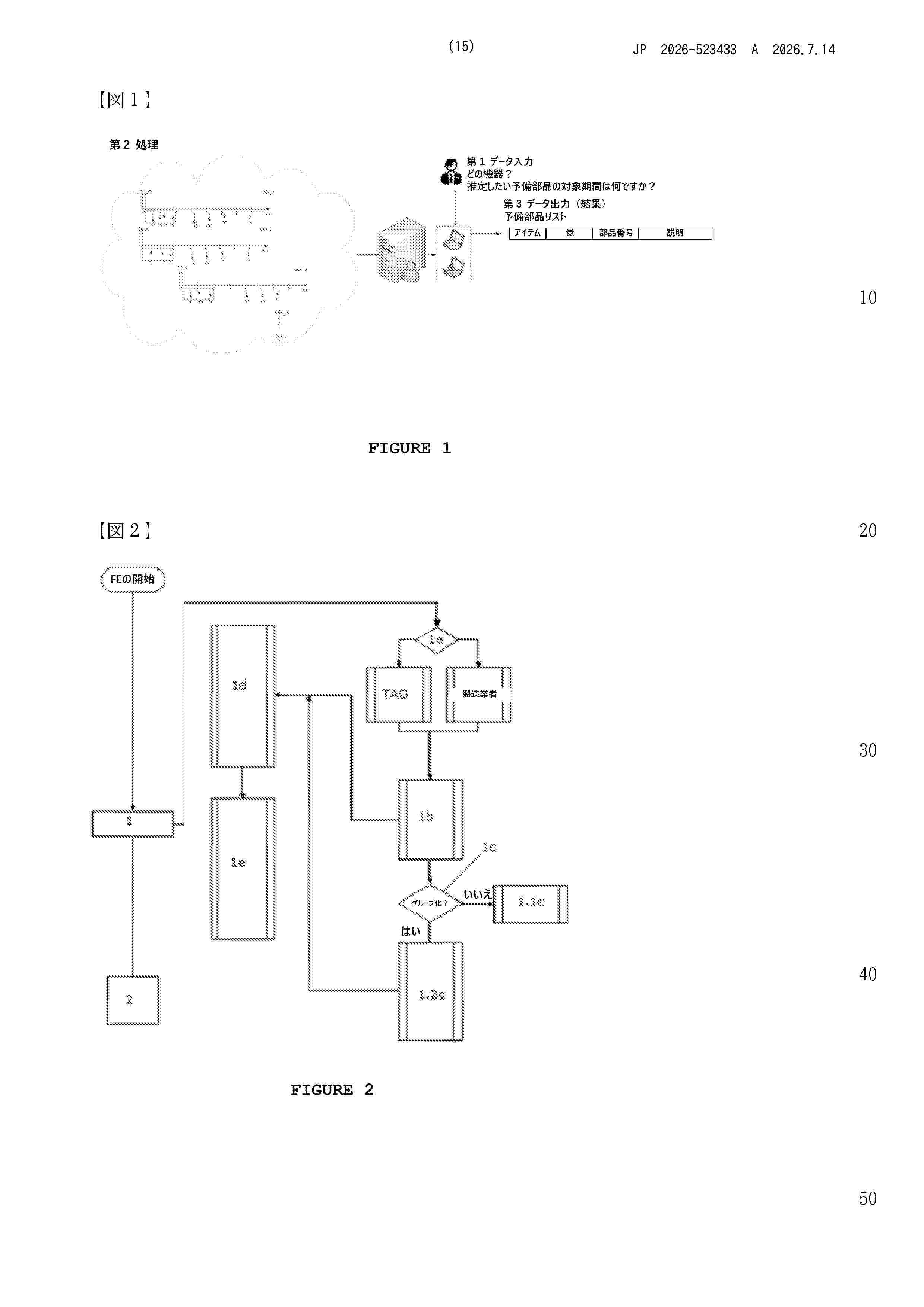
0001 Disclosed are systems for producing a pharmaceutical excipient associated with a digital asset, methods for producing a pharmaceutical excipient associated with a digital asset, apparatuses for generating a digital asset, computer-implemented methods for generating a chemical passport, computer program elements for generating a digital asset, uses of a pharmaceutical excipient associated with a digital asset, uses of a digital asset, products produced from the pharmaceutical excipient and associated with a digital asset, a digital asset including one or more decentral identifier(s) and data related to the environmental impact data, apparatuses for producing a product associated with the digital asset and methods for producing a product associated with the digital asset.
Resumen de: EP4279429A1
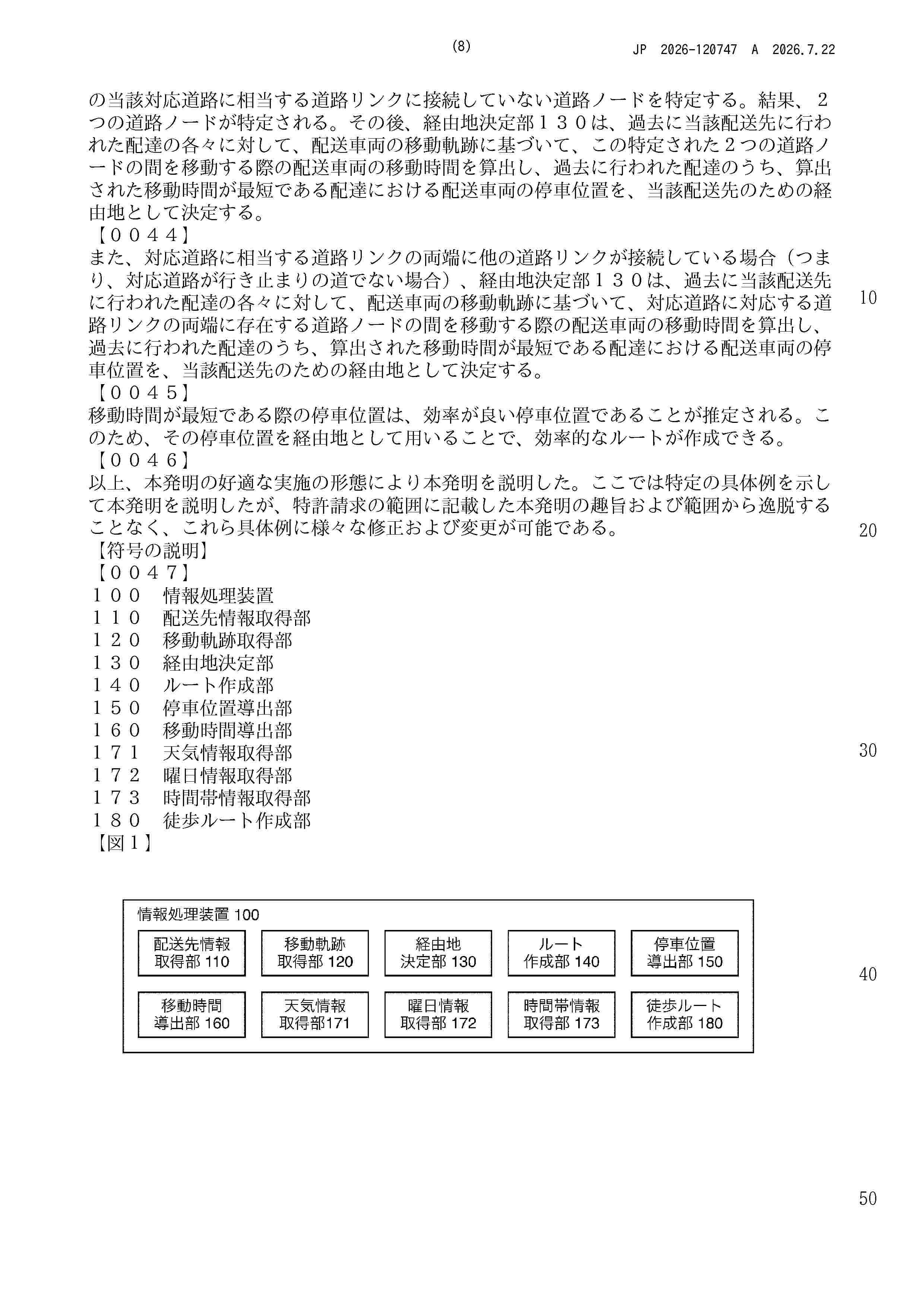
A route in which a stop position of a delivery vehicle is taken into account is created. When creating a route, for each of one or more delivery destinations, a travel trajectory of a delivery person and a travel trajectory of a delivery vehicle in one or more deliveries made to the delivery destination is acquired, and, for each of the one or more delivery destinations, a transit point for the delivery destination is determined based on a travel trajectory of a delivery person and a travel trajectory of a delivery vehicle in each of one or more deliveries made to the delivery destination.
Resumen de: CN122434405A
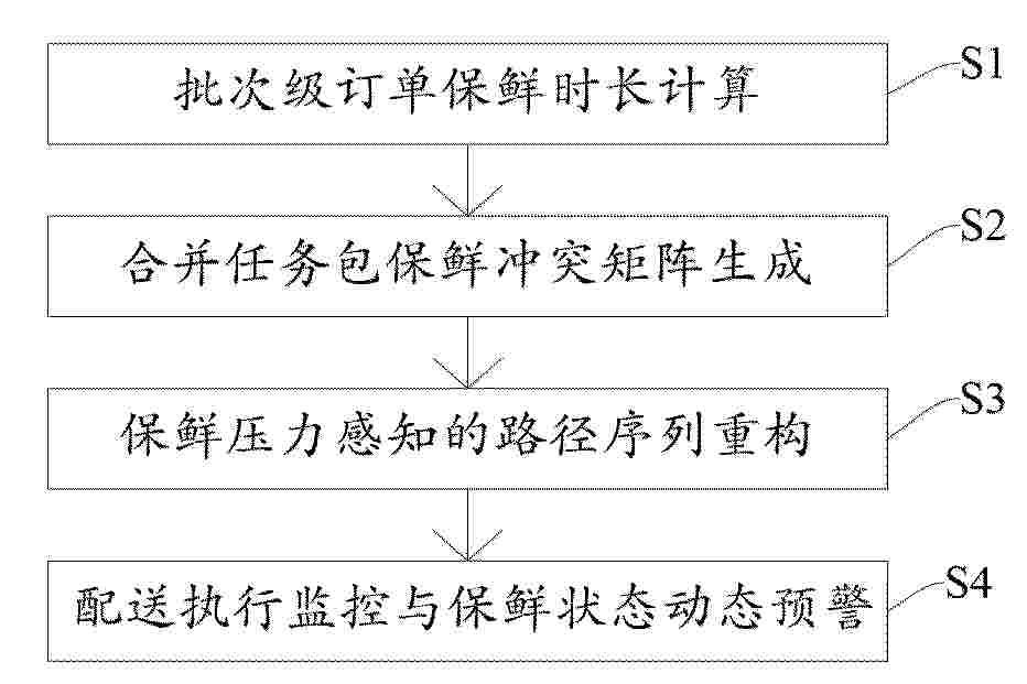
本发明属于物流调度技术领域,涉及基于多维数据的农产品物流路径规划方法及系统。其方法包括:提取待配送订单的原始记录并关联产品品类标识与采收时间戳,实时计算每笔订单的批次剩余保鲜时长,将保鲜不可达订单从合并配送队列中剔除;为合并配送队列内各订单计算保鲜压力系数,构建冲突矩阵并识别出保鲜冲突对集合;将冲突对转化为路径序列的强制前置约束注入车辆路径问题求解器的约束层,在可行解空间内以总里程最短为目标函数进行路径搜索输出路径方案;将路径方案下发至配送端并在配送执行阶段持续维护实时保鲜状态监控链路。本发明有效降低了合并配送任务包中因排序不当引发的末端货损概率。
Resumen de: CN122434392A
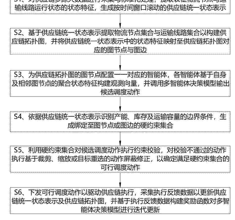
本发明提供了一种基于人工智能的供应链管理方法,包括:首先通过大数据采集链路获取供应链各物流节点与运输线路的业务数据和运行数据,构建统一的供应链状态表示;在此基础上构建带状态特征的供应链拓扑图,并为各物流节点配置对应的智能体,形成多智能体增强学习决策模型。各智能体基于供应链拓扑图输出候选调度动作,并结合产能约束、库存上下限约束、运输容量约束及服务时限约束生成硬约束集合,对候选调度动作进行动作屏蔽与修正,确定满足硬约束集合的可行调度动作。随后将可行调度动作下发执行,并采集执行反馈数据以更新供应链状态表示和拓扑结构,构造训练样本对多智能体增强学习模型进行迭代更新。
Resumen de: CN122434415A
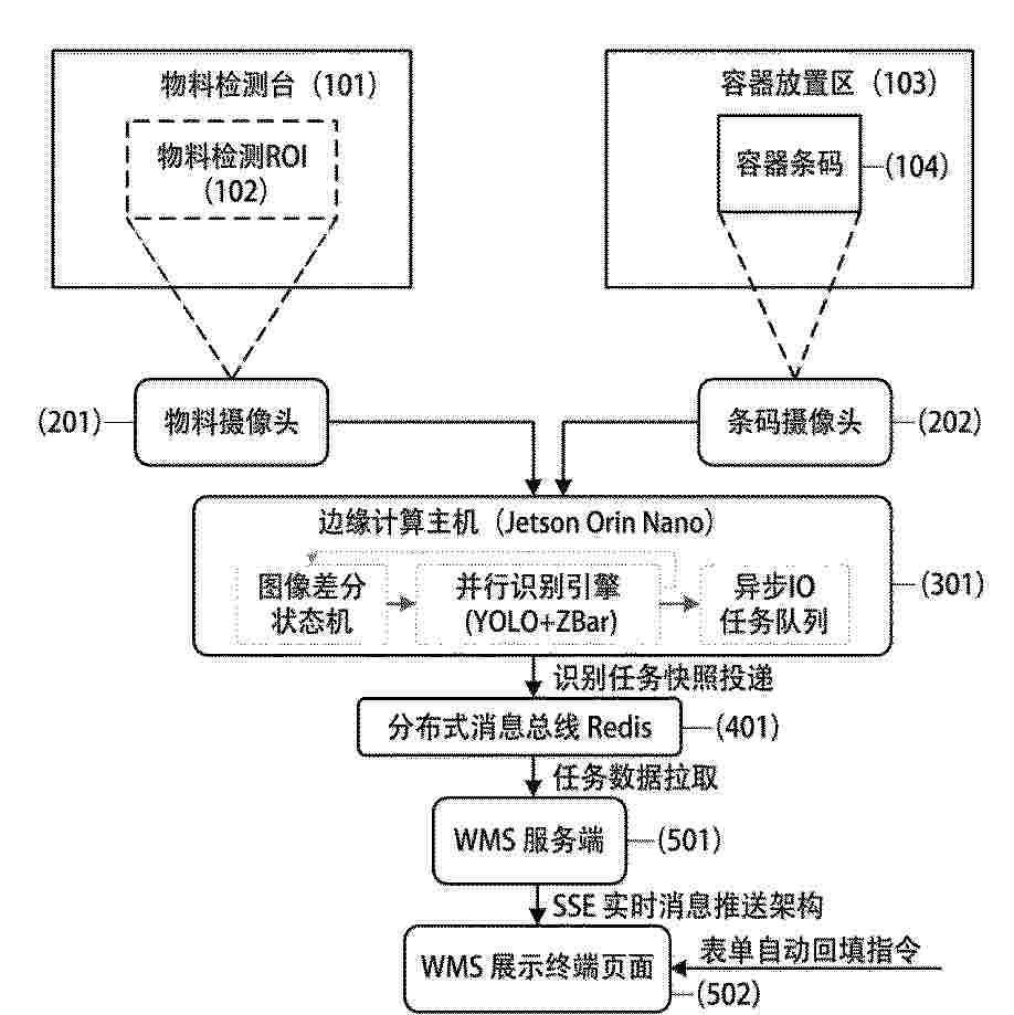
本发明公开了一种基于边缘视觉感应的仓储智控系统,包括:感知模块、边缘算力模块、消息总线模块、WMS服务模块与交互模块,其作业方法包括以下步骤:系统镜像化部署;进行入库作业和出库作业的配置模式设置与交互式校准;入库作业;出库作业;异常纠偏与样本归档;自动复位。本发明采用边缘视觉与图像差分无感触发,替代物理传感器与人工扫码录入,大幅减少非生产操作,显著提升仓储作业流畅度与效率,入库出库双模式自适应,通过异构视觉并行识别与实时消息推送,实现系统主动驱动物流,亚秒级响应并实时拦截错拣,搭载双链路纠偏与样本自进化闭环,数据可全程追溯,支持远程可视化运维,识别准确率随使用持续提升。
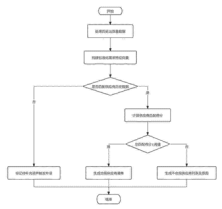
Resumen de: CN122434427A
本发明公开了一种检修服务的采购计划报表的处理方法及系统,首先处理供应商历史出货量数据,构建多级标签体系及历史采购项目服务表现数据库;然后基于调整后的NLP模型提取需求实体,生成标准化特征向量;并将需求特征与出货量标签映射,未匹配则补录;最后计算四维度得分,结合历史服务数据动态分配权重,得总匹配得分;设场景化阈值筛选合规供应商;标注不合规原因;本方法有效提升了供应商筛选精准性,解决现有技术依赖模糊或单一维度匹配、未关联历史出货量关键属性与采购需求导致不合规供应商混入的问题,增强了匹配结果与供应商实际服务能力的关联性,解决了现有技术维度权重主观固定且与实际服务质量脱节的问题。
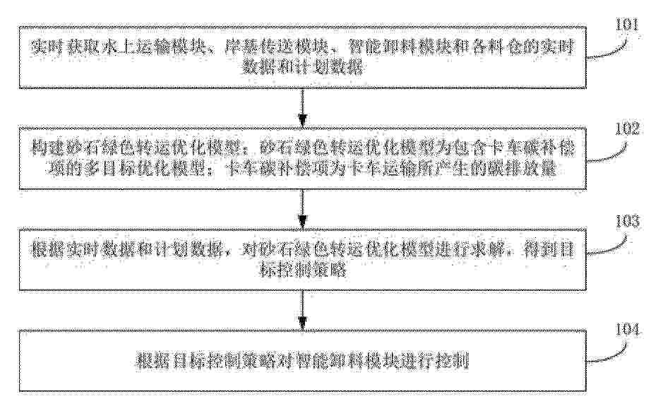
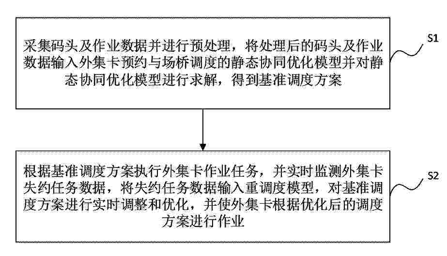
Resumen de: CN122433983A
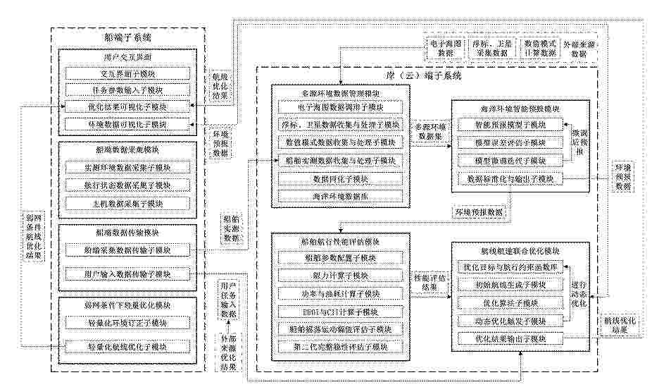
本申请涉及越江跨海桥梁、隧道等大型交通工程的施工物流与绿色建造技术领域,具体涉及一种船岸协同的砂石绿色智能融合转运控制系统及方法,方法包括:实时获取水上运输模块、岸基传送模块、智能卸料模块和各料仓的实时数据和计划数据;构建砂石绿色转运优化模型;砂石绿色转运优化模型为包含卡车碳补偿项的多目标优化模型;卡车碳补偿项为卡车运输所产生的碳排放量;根据实时数据和计划数据,对砂石绿色转运优化模型进行求解,得到目标控制策略;根据目标控制策略对智能卸料模块进行控制。
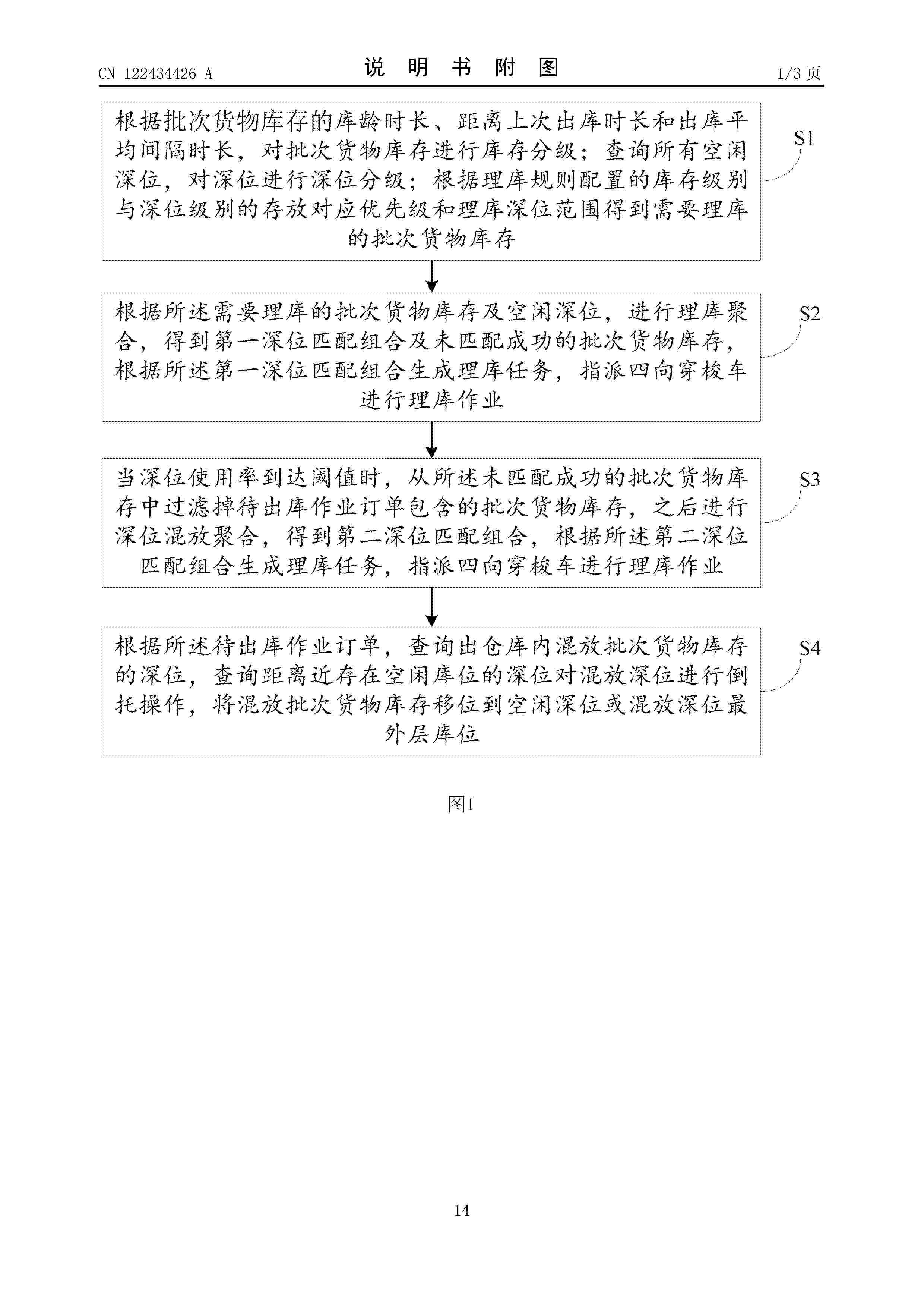
Resumen de: CN122434426A
本发明公开了一种自动化立体库多深位理库的方法及装置、电子设备、介质,包括:对批次货物库存进行库存分级和对深位进行深位分级;根据理库规则配置的库存级别与深位级别的存放对应优先级和理库深位范围得到需要理库的批次货物库存;根据需要理库的批次货物库存及空闲深位,进行理库聚合,得到第一深位匹配组合及未匹配成功的批次货物库存;当深位使用率到达阈值时,从未匹配成功的批次货物库存中过滤掉待出库作业订单包含的批次货物库存,之后进行深位混放聚合,得到第二深位匹配组合;查询待出库的混放批次货物库存的深位,查询存在空闲库位的深位及空闲深位对混放深位进行倒托操作,将混放批次货物库存移位到空闲深位或混放深位最外层库位。
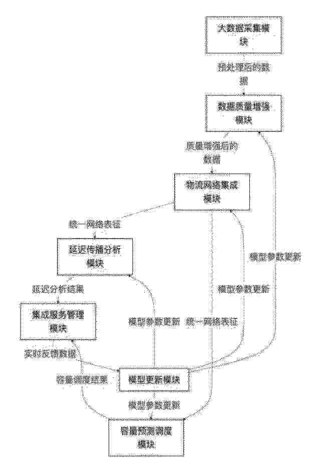
Resumen de: CN122434384A
本发明公开了一种基于大数据的物流信息集成服务管理系统,包括大数据采集模块、数据质量增强模块、物流网络集成模块、延迟传播分析模块、容量预测调度模块、集成服务管理模块和模型更新模块。系统通过条件生成对抗网络修复缺失数据,通过分层图嵌入算法构建统一的多层级物流网络表征,通过因果森林模型挖掘延迟传播链并提供精准干预策略,通过多尺度时序卷积网络预测容量需求并实现弹性调度。本发明有效解决了物流信息集成度低、延迟分析能力弱、数据质量差、资源调度效率低的技术问题,为物流企业提供智能化的信息集成服务和决策支持。
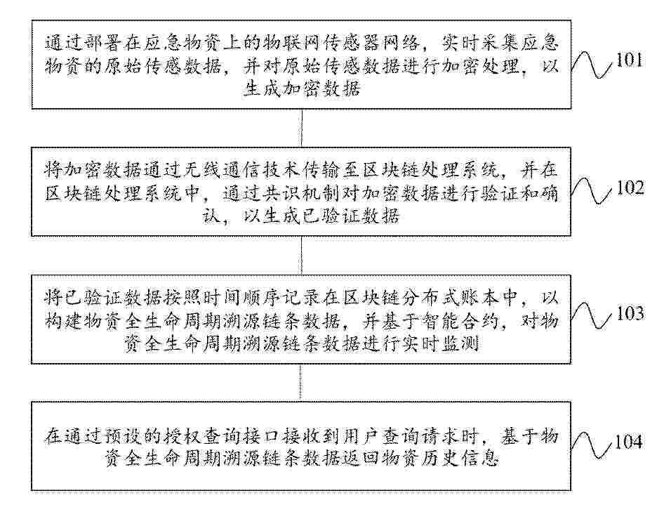
Resumen de: CN122434383A
本申请公开了一种基于物联网与区块链的应急物资管理方法、设备及介质,涉及应急物资管理技术领域。方法包括:通过部署在应急物资上的物联网传感器网络,实时采集应急物资的原始传感数据,并对原始传感数据进行加密处理,以生成加密数据;将加密数据通过无线通信技术传输至区块链处理系统,并在区块链处理系统中,通过共识机制对加密数据进行验证和确认,以生成已验证数据;将已验证数据按照时间顺序记录在区块链分布式账本中,以构建物资全生命周期溯源链条数据,并基于智能合约,对物资全生命周期溯源链条数据进行实时监测;在通过预设的授权查询接口接收到用户查询请求时,基于物资全生命周期溯源链条数据返回物资历史信息。
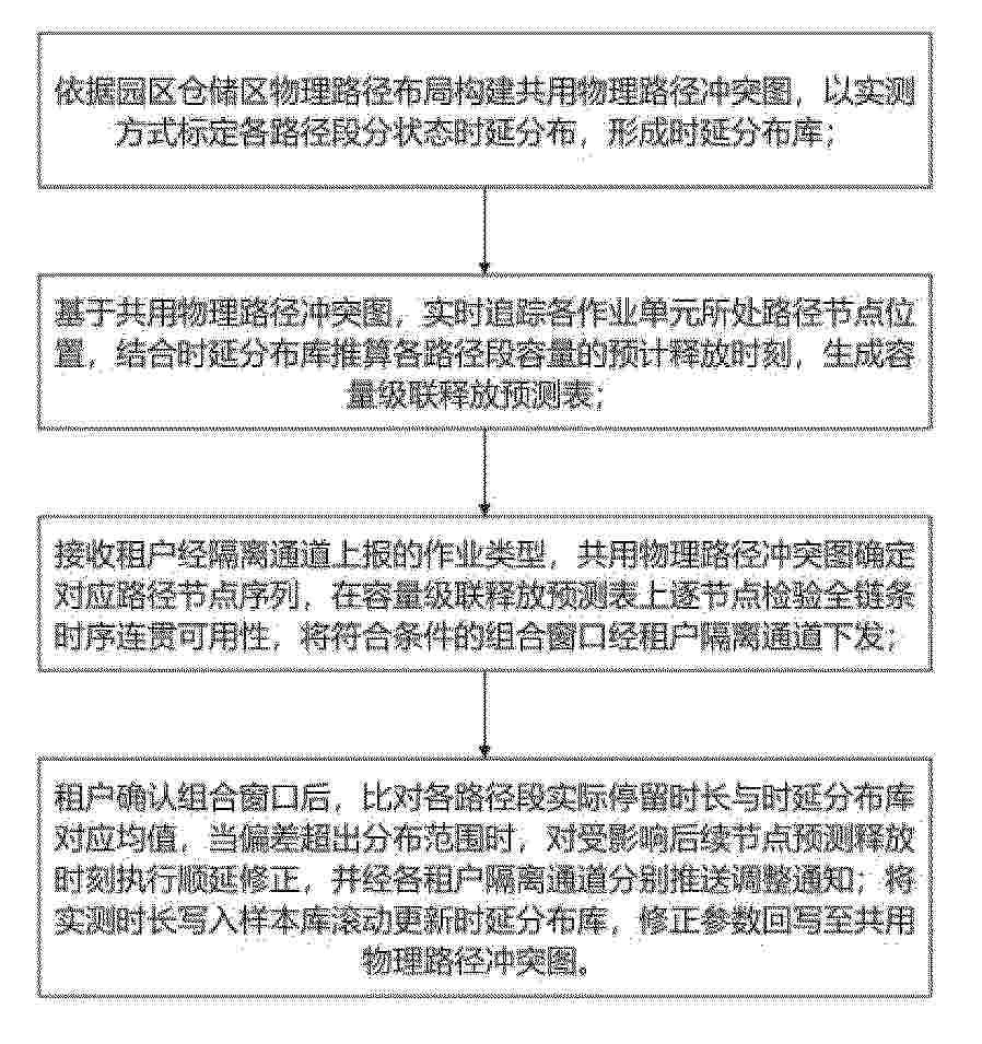
Resumen de: CN122434181A
本发明涉及智慧园区管理技术领域,具体为一种基于大数据的智慧园区信息管理系统,本发明通过构建共用物理路径冲突图,对园区内各类作业路径关系及容量约束进行统一建模,并通过实测数据标定形成时延分布库。在此基础上,实时跟踪作业单元位置,结合时延分布参数生成容量级联释放预测表,并依据作业类型路径链逐节点校验时序连贯性,生成有效组合窗口供租户选择。进一步引入偏差触发判定与级联修正机制,对实际运行偏差进行动态修正,同时通过样本库滚动更新时延分布参数并回写冲突图,实现模型自适应优化。该方法能够提高路径资源利用率,降低冲突概率,增强多租户环境下调度的准确性与稳定性。
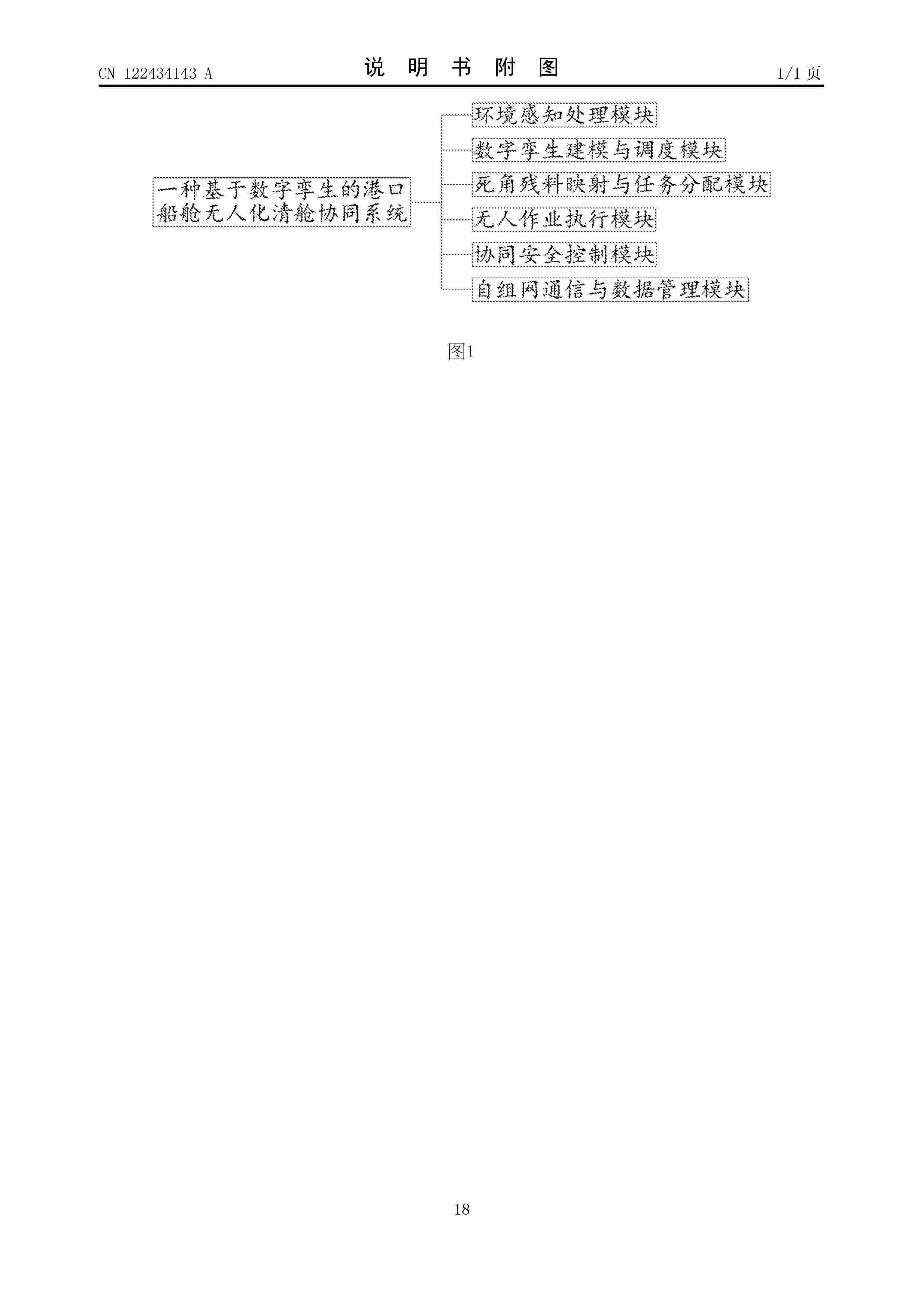
Resumen de: CN122434143A
本发明涉及港口船舱清舱技术领域,尤其涉及一种基于数字孪生的港口船舱无人化清舱协同系统,该系统包括:环境感知处理模块对舱内原始感知数据进行高粉尘场景精度补偿处理;数字孪生建模与调度模块构建船舱三维网格模型并生成清舱调度指令;死角残料映射与任务分配模块生成残料分布更新数据及任务分配指令;无人作业执行模块执行清舱作业并输出设备状态数据;协同安全控制模块生成联动控制指令;自组网通信与数据管理模块构建双链路通信拓扑并执行数据传输与存储。本发明中,通过多模块协同构建无人化清舱闭环体系,实现数据互通与流程自动衔接,解决传统人工分步作业难以连续运行的问题。
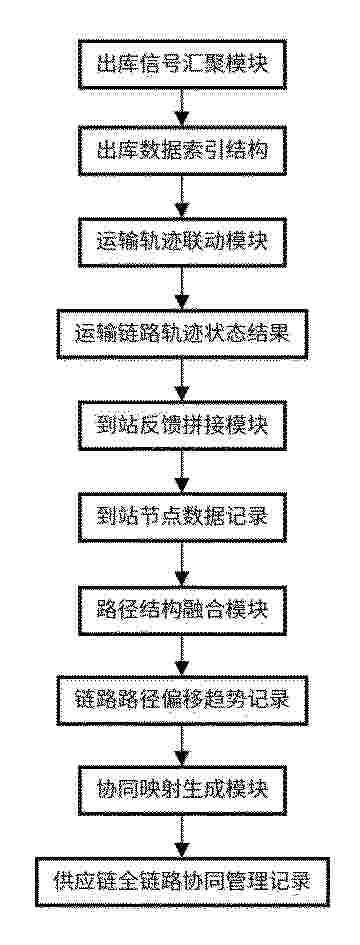
Resumen de: CN122434412A
本发明涉及供应链协同技术领域,具体为基于多源异构数据融合的供应链全链路协同管理系统及方法,包括出库信号汇聚模块、运输轨迹联动模块、到站反馈拼接模块、路径结构融合模块、协同映射生成模块。本发明中,通过对家居出库、运输、到站等节点数据的结构化汇聚、时间戳标定及索引映射,建立起条码与轨迹之间的双向联动关系,通过轨迹编号与时间窗口的动态匹配实现路径状态识别与链路中断分析,通过收发过程的双重校验机制提取路径偏移趋势并构建偏移记录,通过节点时序与路径结构的融合整合各节点数据流向与状态流转,实现装配出库至接收签收过程的全过程映射整合,实现家居供应链全链路的动态优化与精准管控。
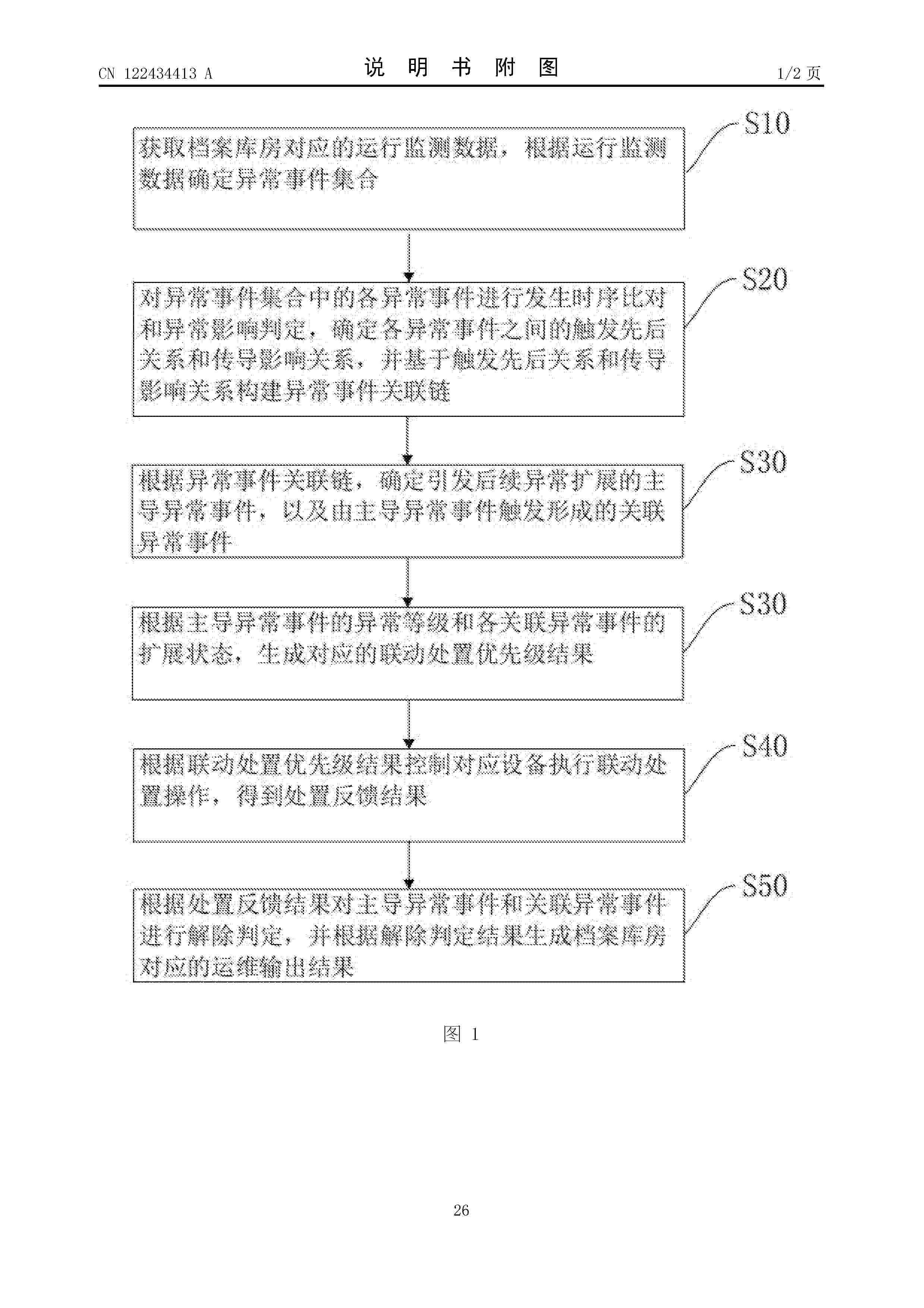
Resumen de: CN122434413A
本发明涉及智能运维的技术领域,尤其是涉及一种档案库房智能运维与AI防控方法、装置、设备及介质,其方法包括对异常事件集合中的各异常事件进行发生时序比对和异常影响判定,确定各异常事件之间的触发先后关系和传导影响关系,并基于触发先后关系和传导影响关系构建异常事件关联链,根据异常事件关联链,确定引发后续异常扩展的主导异常事件,根据主导异常事件的异常等级和各关联异常事件的扩展状态,生成对应的联动处置优先级结果,根据联动处置优先级结果控制对应设备执行联动处置操作,得到处置反馈结果,根据处置反馈结果对主导异常事件和关联异常事件进行解除判定,并根据解除判定结果生成档案库房对应的运维输出结果。
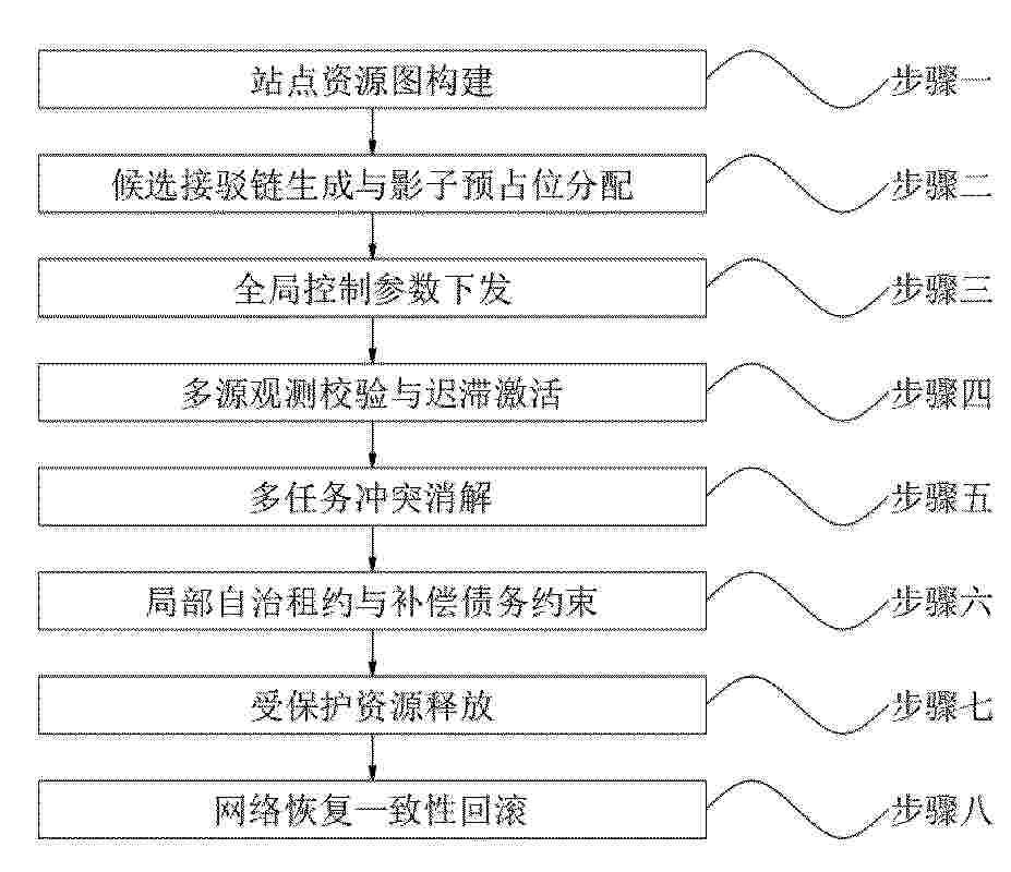
Resumen de: CN122434175A
本发明公开了一种平台侧低空物流地空接驳资源控制系统及方法,方法包括:步骤一,站点资源图构建;步骤二,候选接驳链生成与影子预占位分配;步骤三,全局控制参数下发;步骤四,多源观测校验与迟滞激活;步骤五,多任务冲突消解;步骤六,局部自治租约与补偿债务约束;步骤七,受保护资源释放;步骤八,网络恢复一致性回滚;本发明将平台资源控制与真实物理资源图深度绑定,避免资源管理停留在抽象数据库层,通过影子预占位与激活纪元管控提升站点资源利用率,结合动态迟滞激活抑制各类扰动引发的状态误切换,通过租约式自治与受保护释放平衡执行效率与稳定性,依托代理签封与一致性回滚增强弱链路、低算力终端场景的系统鲁棒性。
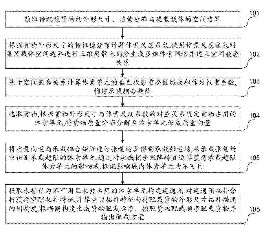
Resumen de: CN122433409A
本发明公开了一种件杂货配载三维空间离散化仿真方法,属于物流仿真与智能配载技术领域,包括:根据货物外形尺寸特征值分布计算体素尺度系数,对集装载体空间进行三维离散化剖分生成体素网格并建立空间嵌套关系,构建承载耦合矩阵;将货物质量分布分解至体素单元形成质量向量,与承载耦合矩阵进行张量运算得到承载张量场,识别承载超限体素单元并标记其影响域为不可用;提取未标记为不可用且未被占用的体素单元构建连通图,对连通图拓扑分析获得空隙拓扑特征,计算空隙拓扑特征与待配载货物外形尺寸拓扑描述的同构度,根据同构度生成货物配载顺序并输出配载方案。本发明提高了配载空间利用率和承载安全性。
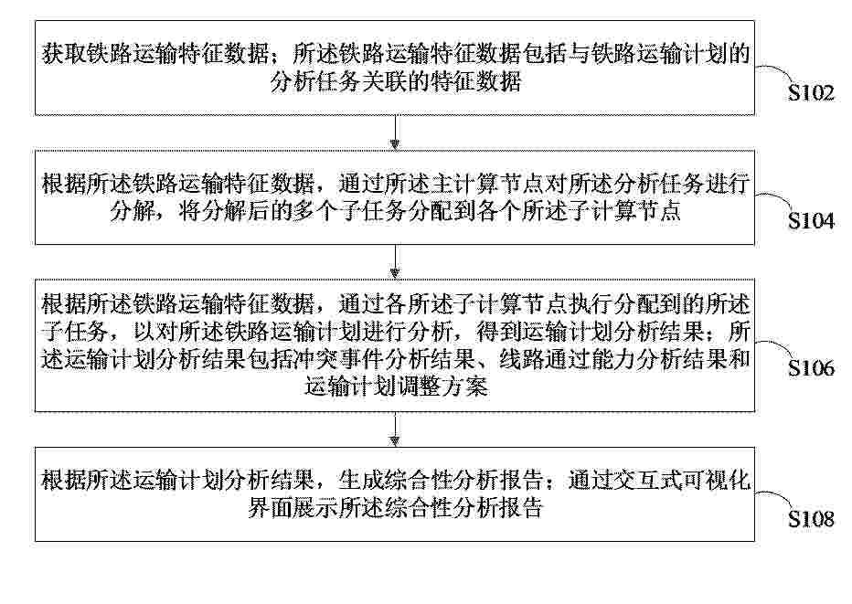
Resumen de: CN122434389A
本申请涉及一种基于分布式计算的铁路运输计划分析方法、装置、计算机设备、可读存储介质和计算机程序产品。所述方法包括:获取与铁路运输计划的分析任务关联的铁路运输特征数据;根据铁路运输特征数据,通过主计算节点对分析任务进行分解,将分解后的多个子任务分配到各个子计算节点;根据铁路运输特征数据,通过各子计算节点执行分配到的子任务,以对铁路运输计划进行分析,得到包括冲突事件分析结果、线路通过能力分析结果和运输计划调整方案的运输计划分析结果;根据运输计划分析结果,生成综合性分析报告;通过交互式可视化界面展示综合性分析报告。采用本方法可以能够在运输计划分析中提高铁路运输数据处理效率。
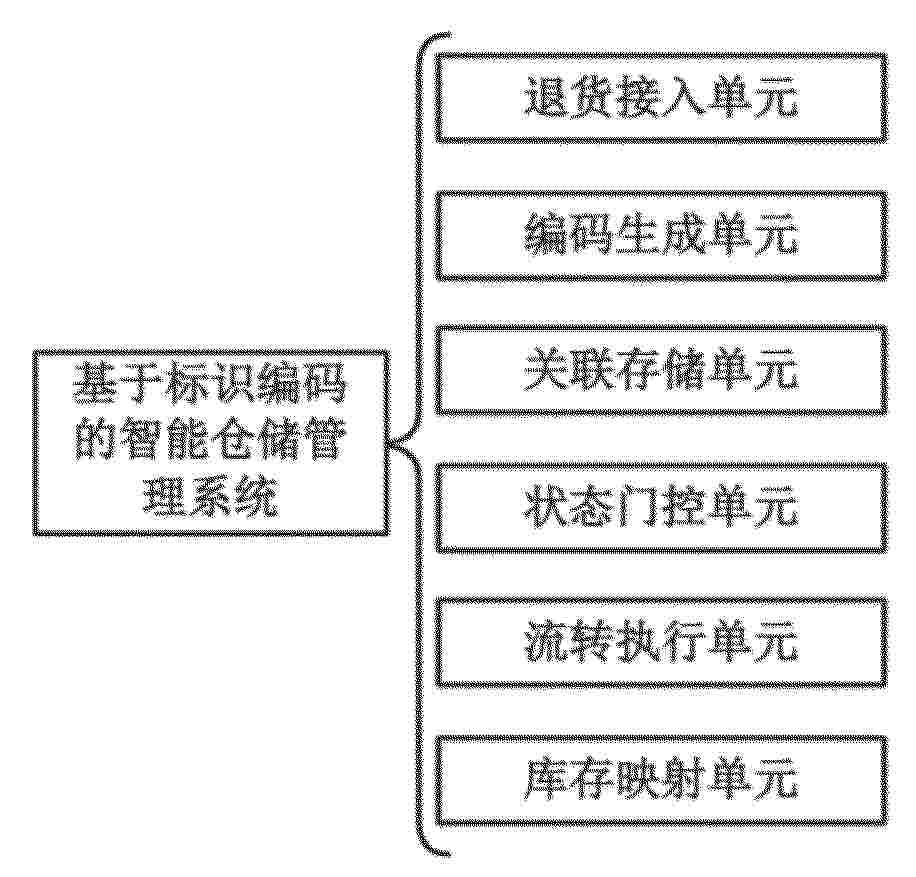
Resumen de: CN122434416A
本发明公开了一种基于标识编码的智能仓储管理系统,涉及智能仓储与退货逆向物流处理技术领域,本发明通过退货实例根编码、对象编码和事件编码构成分层编码链,并在同一退货实例根编码下记录来源关联、并行关联和合流关联,系统把整件退货在拆包后形成的多个处理对象持续约束在同一关联范围内;再结合状态门控单元对待流转对象编码执行来源关联连续校验、对象完整性校验和状态归属校验,能够在主机对象、附件对象、包装对象分别流转至不同区位的处理中,阻断来源不连续、对象不完整或者状态不归属的对象继续进入后续环节,从而减少拆分后对象错配重组、状态记录相互脱节以及异常件继续流入正常处理链的情况。
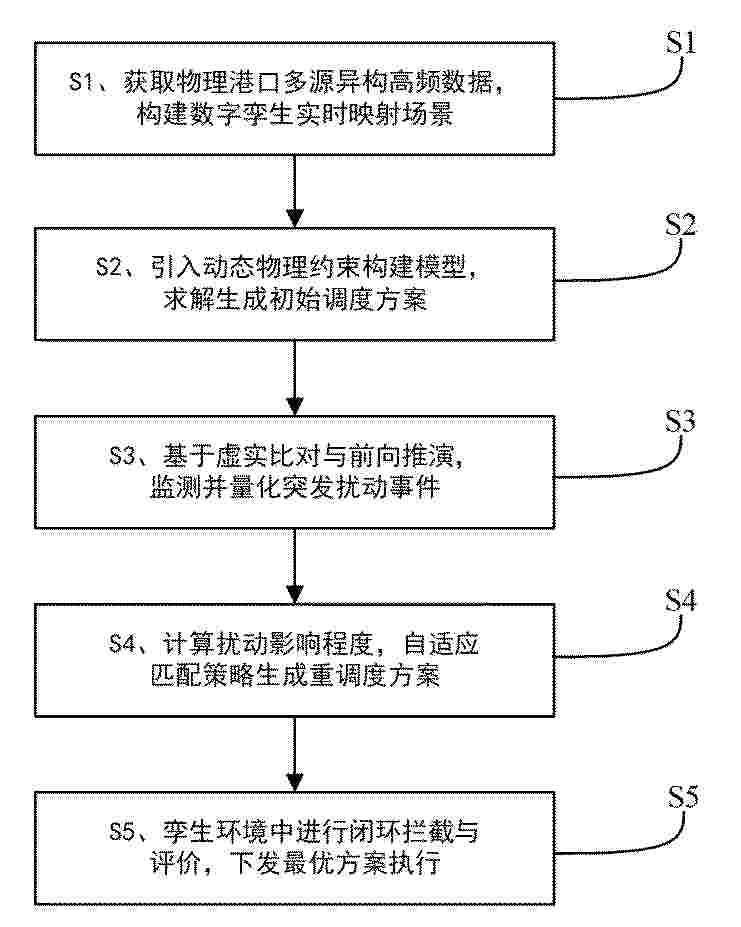
Resumen de: CN122434393A
本发明属于港口航运调度与智能决策技术领域,公开一种基于数字孪生的船舶进出港动态调度方法。持续获取物理港口多源异构数据,构建全要素动态映射的实时运行场景,实现非对称安全间隔边界的动态拓展。依托场景动态边界,构建协同调度模型,利用多目标优化算法在强制性物理约束下寻优生成初始方案。通过虚实连续比对与前向时空推演机制判定扰动,生成扰动表征参数。基于扰动影响指标与预设动态阈值,选择局部调整或全局重排策略生成重调度方案。最后,在虚拟环境中进行前向时空推演,校验实现冲突拦截与重新寻优,并结合调度效率与方案稳定性指标进行动态加权综合评价,选取最优方案。本发明实现了自适应动态闭环管控与物理执行安全的双重保障。
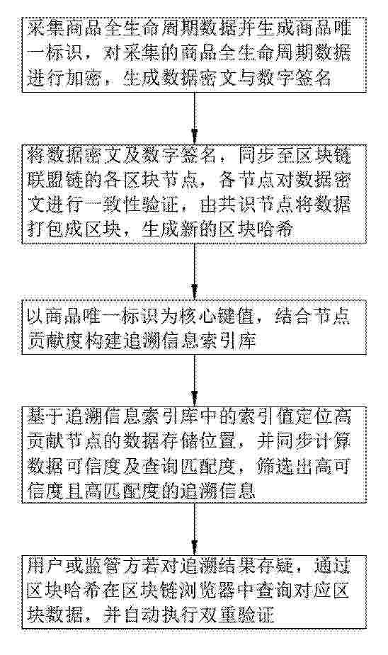
Resumen de: CN122434543A
本发明公开了基于区块链的电商物流追溯方法及系统,涉及电商物流追溯技术领域,包括以商品唯一标识为核心键值,结合节点贡献度构建追溯信息索引库;本发明通过量化计算节点贡献度,结合商品唯一标识、流通环节编号及时间戳构建结构化追溯信息索引库,能够精准定位高贡献、高可靠节点的数据存储位置,大幅提升追溯查询效率,避免全链遍历的资源浪费;再者,建立数据可信度与查询匹配度的双重量化评估机制,科学判断追溯信息的真实性与适配性,解决传统追溯缺乏权威评估标准的问题,强化追溯结果的权威性;最后,双重验证机制通过区块哈希校验与节点信任值复核,在用户或监管方存疑时快速核查数据一致性、排查节点异常。
Resumen de: CN122434434A
本申请涉及采购治理与人工智能决策支持领域,尤其涉及一种基于AI的集中采购治理中枢的裁量权治理方法,该方法根据目标业务的业务特征信息进行裁量判定,响应于裁量判定的结果为需要裁量,根据业务特征信息和预设的裁量规则库生成目标业务对应的多个裁量处理路径,并进行路径评估,得到目标裁量路径以及评估结果说明。为目标裁量路径配置对应的权限边界参数得到用于治理目标业务目标裁量方案,对确定目标方案的过程进行记录留档,用于后续进行调用和追溯。本申请无需人工介入自动评估是否需要启动裁量,评价结果客观且可靠性强。进一步自动进行业务裁量,自动评估选择裁量方案,提高裁量效率并使得裁量结果具有可解释性。
Resumen de: CN122435809A
一种空路联运货场低空空域交通决策控制方法及系统,涉及低空空域交通决策控制领域,解决现有多架无人机在货场共享低空空域内执行货物短驳、场内转运、跨区接驳和时效补运时产生的进离场放行、航路通行许可、冲突探测与解脱、等待盘旋控制、流量均衡控制、动态受限空域绕避控制等问题,所述方法包括采集空路联运货场地和空交通运行数据,完成地空映射与资源单元化,搭建综合代价优化模型;求解得到无人机任务与时隙的匹配集合,生成通行方案并设立决策变量,构建空域控制约束模型;采用逻辑分解算法迭代求解,通过主、子问题交互验证直至收敛,得到最优空域决策方案;解码生成可执行指令,滚动更新空域状态,实现动态管控。
Resumen de: CN122435360A
本发明涉及图像识别技术领域,公开了基于机器视觉的进出口全链路异常货物目标识别系统,包括:获取机检图像并经校正得到双能衰减图;基于此反推集装箱构架坐标以构建空气连通流形;接着在原生空腔内计算额外实体衰减残差,并计算该残差对空气通路连续性造成的局部风道连通阻断量;最终结合残差与阻断量提取顺流空腔侵入参量,选取该参量极大的候选区域并输出类别概率。本发明不依赖开箱,通过定位异常物品对通风走向的侵入与阻断表现,有效提升了冷链机检图像中隐蔽目标的检出率。
Resumen de: CN122434590A
本发明公开基于AI的车联网商品智能运营方法及系统,采集商品运营数据与竞品市场数据,通过价格节律耦合解析生成预调价触发标识;检测库存积压速率并结合竞品基准集建立调价监控规则表;基于收藏夹滞留行为识别调价缺口品类,对调价监控规则表进行权重调配生成运营调控规则集,并开展竞品跟价响应速度超限核查确定干预阈值节点;依据干预阈值节点激活调价行为序列,提取车主点击未购买特征生成推荐缺口系数,执行互补品关联推荐走势监测生成动销合规度;基于动销合规度分析干预复现周期,实施搜索词与成交品类偏差率校准生成品类运营画像,对比品类运营画像与商品运营数据输出智能运营评估结果,提升了车联网商品调价决策的精度与时效性。
Resumen de: CN122434410A
本发明公开了一种仓储多AGV集成调度及分层路径协调方法及系统,属于智能仓储多AGV调度技术领域。本发明将订单拆解为货架搬运任务集合,量化订单延迟成本,构建AGV运营成本与订单延迟成本之和最小化的统一优化目标;采用ALNS+SA混合算法一体化优化任务分配、执行顺序与充电决策;通过双模态时空路径规划、分级冲突消解、死锁回滚重调度构建分层协调机制,形成全流程闭环。本发明兼顾运营成本与订单履约时效,降低拥堵死锁概率,大幅提升系统吞吐能力、设备利用率与方案鲁棒性,适用于各类货到人智能仓储的多AGV协同作业场景。
Resumen de: CN122434404A
本发明属于智慧园区及数据处理技术领域,提供一种用于园区管控的叉车数据处理方法、系统及应用,该方法包括获取叉车的多源运行数据及环境基础设施的多源状态数据;基于预设的数据分级策略进行分级,针对不同级别的数据执行差异化的边缘预处理;对分级数据流进行解析处理,并与实时园区状态进行关联以构成规则校验上下文;基于园区多维规则引擎进行空间约束校验、多车协同校验及任务时效校验,并结合校验结果及实时园区状态动态计算各分级数据流的调度优先级,生成调度队列;生成实时调度决策指令,下发至对应叉车终端,并同步更新园区全局状态缓存。本发明能解决现有园区叉车管控中存在的延迟高、数据筛选缺乏园区场景针对性、无优先级等问题。
Resumen de: CN122434398A
本申请涉及数据分析技术领域,尤其涉及基于环境评估的金丝猴粪便保存管理系统及方法,本申请通过监测金丝猴粪便的物理性状、粘膜状态及储存环境,结合定量化异常分析方案,实现了对粪便变质风险的早期评估与分级预警,从而能动态优化运输保存方式,有效减少样本在转运过程中的变质,提升粪便样本用于科研或健康监测的可靠性与保存质量。
Resumen de: CN122434420A
本发明涉及仓储物流调度技术领域,公开了一种云仓出库订单分配方法,包括以下步骤:接收出库订单执行多维合规性校验,计算复杂度维度值生成初始出库波次池;构建全维度库存画像,建立可用库存与终端执行设备的空间映射关联;采集设备微观物理特征数据,代入故障预见模型计算故障发生概率;若概率大于预警阈值,判定设备处于亚健康状态,执行波次解绑逻辑将高复杂度订单路由至健康设备,执行动态降维分配逻辑将低复杂度订单指派至该亚健康设备,生成全局出库分配方案;执行可行性校验通过后下发出库执行指令。本发明避免了单点硬件突发故障导致复杂波次任务长时间停滞的问题,提高了多设备协同出库时的整体稳定性。
Resumen de: CN122434151A
本申请提供了一种码头堆场排产管理方法及装置、电子设备、可读存储介质,属于排产管理技术领域,该方法包括:基于码头的航道信息和船舶的基本信息确定目标作业需求;基于目标作业需求从多个装卸货策略中确定目标装卸货策略,其中,多个装卸货策略的控制精度不同;基于目标装卸货策略对码头堆场进行排产管理。本申请提供的码头堆场排产管理方法及装置、电子设备、可读存储介质可以提高码头堆场整体作业效率。
Resumen de: CN122434394A
本申请公开了一种面向智慧物流的多智能体协作配送方法及系统,涉及协作配送技术领域,其包括控制第二协作智能体产生预设共振频率的震动信号,同步采集包裹受激生成的复检响应信号;依据复检响应信号的偏度特征与峰度特征计算特征突变率;若特征突变率大于预设突变阈值,跳出无损复检循环并生成隔离拦截数据;若特征突变率不大于预设突变阈值,跳出无损复检循环并输出继续配送指令;当获取到隔离拦截数据时,控制第二协作智能体广播异常信标,根据异常信标生成逆向交接坐标数据,调度逆向处理智能体前往逆向交接坐标数据对应的位置完成交接。本申请具有提高协作配送效率的效果。
Resumen de: CN122434414A
本发明属于物流仓储系统仿真技术领域,公开了一种货物按指定数量和位置入库的仿真实现方法,包括以下步骤:S1、铺设实体模块;S2、设置实体功能属性;S3、定义货架拉入货物的拉入策略;S4、创建货物入货架列的逻辑;S5、创建货物入货架层的逻辑:返回货架层数的数值标签。本发明中自动化立体仓库货物按要求入库的行为与控制系统的控制逻辑相吻合,可以保证仿真效果的真实、仿真结果的准确。
Resumen de: CN122434203A
本发明公开了一种动态封控路网下应急投放点选址与车辆调度优化方法,包括:获取应急投放点选址与车辆调度优化的基础数据集;基于基础数据集,确定稳定候选投放点集合;基于基础数据集,构建时变开放路网,确定动态可达关系、动态路网距离和动态通行时间;基于稳定候选投放点集合、动态可达关系、动态路网距离和动态通行时间,生成候选投放点启用方案和需求点分配方案;对候选投放点启用方案和需求点分配方案进行可行性校验,基于通过可行性校验的方案,生成车辆调度方案;对候选投放点启用方案、需求点分配方案和车辆调度方案进行一体化评价,确定应急投放点选址与车辆调度方案;稳定候选投放点集合不变,滚动更新应急投放点选址与车辆调度方案。
Resumen de: CN122433015A
本申请公开了一种基于TFDS的货车故障识别方法、装置、设备及存储介质,属于铁路货车故障检测技术领域。该方法包括:获取由TFDS智能识别输出的货车的部件识别结果,并将部件识别结果分别存储到数据库和高速缓存中;基于预设事故车故障清单对部件识别结果进行故障匹配,得到目标故障信息;基于目标故障信息通过故障权重累加计算货车的故障权重得分,在故障权重得分达到预设权重阈值且高速缓存中不存在货车对应的事故车标识时,将货车标记为事故车并将事故车标识添加到高速缓存中;将货车的事故车标识推送到运维平台,以生成检修工单。可以基于故障清单匹配和故障权重加权计算故障权重得分来准确识别事故车,标记为事故车标识,提高识别准确性和效率。
Resumen de: CN122434545A
本发明公开了一种农产品全产业链溯源与质量安全智能监管平台,包括:安全生产管理系统:升级产业链,建设智慧农业;物流管理系统;全链路可信数据采集系统:部署于产业链各关键节点的物联网设备,确保数据源头真实、实时;区块链可信存证与追溯系统;大数据智能分析系统:接入并融合区块链存证数据、企业上报数据及政府监管数据,利用大数据分析、机器学习模型,构建质量安全风险评估与预警模型;智能监管预警系统;多端协同应用服务系统。本发明通过全链路可信数据采集系统和区块链可信存证与追溯系统;利用区块链的不可篡改、可追溯特性,从根本上解决了农产品溯源数据易造假、公信力不足的问题,建立了产业链各方互信的数据基础。
Resumen de: CN122426491A
本申请涉及一种巷道堆垛机控制方法及仓储管理系统,能够解决空托盘在立体仓库内的自动集约化存储与按需供应的问题,使巷道堆垛机能够自主完成空托盘的叠盘与拆盘全流程。结合将提供核心安全保障的集成检测装置与仓储管理系统进行集成,并进行有机结合,能够构建一个从控制逻辑、系统架构到关键硬件的完整技术方案,极大提高了系统的安全性、连续性以及智能化程度。
Resumen de: CN122434373A
本发明公开了一种细胞治疗产品全流程质量追溯与数字化管理系统,涉及生物医药数字化管理技术领域,本发明通过将每例自体细胞产品注册为链上具有自主状态机的数字代理实体,使产品能够携带自身质控状态和待完成步骤清单,在采集医院、合同生产机构、冷链运输方和回输医院之间自主驱动流转验证与状态更新,以产品去中心化代理协议替代中心化系统流程调度,消除跨组织追溯盲区,物料‑产品异构图谱与溯源模块通过构建异构节点和异质边类型的物料‑产品关联图谱,利用异构图注意力网络计算单段物料使用边的风险传播强度,实现物料质量事件影响范围的双向追溯和风险传播强度的精细量化。
Resumen de: CN122432909A
本申请公开了一种汽车零部件的运输异常行为识别方法及系统,涉及物流运输监控技术领域,解决了现有技术往往使用固定、通用的阈值和模型进行异常判定,无法适应不同路段、不同驾驶习惯带来的正常行为基线差异,导致运输异常行为识别的误报率较高的技术问题;通过运输多源异构数据流构建标准化多源时序数据集和联合特征向量,并以此生成正常行为模式模型和预测值;随后进行异常行为识别和风险评分得到异常事件结果,并以此进行差异化评估与反馈优化得到综合结果,将异常判定从一刀切的静态规则升级为因事而异、因时而变的智能动态学习过程,从而降低误报率,提升识别准确率。
Resumen de: CN122434421A
本申请公开了一种多级产品码异常激活管控方法、系统、设备及介质,其中,方法包括:接收不同入口的开启请求,统一转换为标准激活请求单元,提取激活请求单元的码集合数据集,输出激活请求处理序列;对激活请求处理序列的层级状态数据集执行一致性校验,获得一致性校验结果;根据一致性校验结果基于设备验证结果、操作者信息、时间片段获得事件指纹数据集;将事件指纹数据集与历史窗口比对,识别重复、越级、跨区域或高频异常,输出风险等级标识数据;执行异常操作处理,并对离线终端的上报数据进行幂等去重与顺序纠偏。实施本申请实施例,可以实现在不同业务入口和终端场景下实现一致的产品码激活控制,消除多入口校验逻辑不一致的问题。
Resumen de: CN122437067A
本发明提出了一种基于合作博弈的多能源港口时空协同调度方法,通过引入绿色氢能共享机制并刻画能源‑物流纽带,建立了多港口综合能源系统协同优化模型。系统以多港口联合运行成本最低为全局目标函数,构建了跨港口氢能共享模型,将氢燃料电池船舶创新性地表征为移动储能单元,以实现氢能资源的时空平滑。模型深入考虑了港口物流系统与能源供应的动态耦合,并利用Shapley值法建立公平的成本分摊机制,确保各港口的激励相容与合作稳定性。该模型能够显著降低系统运行成本并大幅提升新能源消纳能力,为多能源港口的低碳化转型及市场化协同运营提供了有力的理论指导与技术支持。
Resumen de: CN122434408A
本发明公开了一种多状态物料存储系统的库位分配与入库路径协同优化方法,包括建立库位分配多目标优化模型,模型包括出入库时间模型、货架稳定性模型、物料关联性模型,并融合物料多状态储存约束和批次管理约束;采用改进灰狼算法求解库位分配多目标优化模型,将入库单物料信息作为输入参数,输出最优库位分配结果。本发明建立了综合考虑多状态物料特性的库位分配多目标优化模型,实现了物料存储的科学化、合理化;设计库位分配与路径规划的协同优化机制,实现了整体作业效率的最大化;适用于液压泵新品研制等多状态、小批量物料的存储管理,显著提升了液压泵新品研制中多状态物料存储系统的入库作业效率和仓储管理水平。
Resumen de: CN122433209A
本申请属于飞机设计技术领域,涉及一种飞机设计物料清单计算效能提升方法。该方法包括:构建软件系统架构,包括用于存储原始设计数据与中间过程数据的存储层、用于执行并行解析与计算的计算层、以及用于管理与分发计算任务的应用层;通过应用层将所述计算任务分发至分布式的计算节点;并行执行产品结构信息提取操作,通过独立于产品数据管理系统服务器许可证的分布式模型解析客户端,对新增的飞机设计模型进行轮询解析,提取模型中的关键信息,将匹配完成的产品结构数据与模型解析结果分发至并行的报表整合任务队列,进行并行数据整合与重组。本申请通过分布式并行计算与异步轮询解析,降低模型解析耗时,提升了飞机设计物料清单计算效能。
Resumen de: CN122434618A
本说明书实施例提供订单处理方法及系统,其中,订单处理方法包括:根据用户的历史交互数据确定目标订单和所述用户针对所述目标订单的用户意图信息;基于所述用户意图信息在订单管理信息集合中确定关联所述目标订单的至少一条订单管理信息,并按照所述至少一条订单管理信息分别对应的优先级信息对所述至少一条订单管理信息进行排序,获得订单管理信息序列;基于所述订单管理信息序列执行所述目标订单关联的订单管理任务,获得订单管理数据,并基于所述订单管理数据更新所述目标订单的订单状态。
Resumen de: CN122433894A
本申请涉及一种融合多阶段决策及约束规则反馈的重载铁路运输大模型实现方法和系统,涉及重载铁路运输技术领域。本申请能够提高重载铁路运输组织的处理效率和智能化水平。方法包括:确定待训练的基座模型,将基座模型进行训练得到重载铁路运输大模型;构建面向重载铁路运输的多阶段智能决策生成架构,将推理过程划分为知识检索阶段、参数推导阶段以及标准或方案生成阶段;引入基于约束规则反馈的推理校验机制,对标准或方案生成阶段输出的候选标准或候选方案进行合规性与安全性校验;在校验通过的情况下将候选标准作为标准输出结果或候选方案作为方案输出结果;在校验不通过的情况下触发二次推理与参数重算,得到标准修正结果或方案修正结果。
Resumen de: CN122434609A
本申请提出一种物流滞期费用数据的确定方法、装置和可读存储介质,方法用于海运物流费用管理系统,方法包括:响应于数据核算指令,获取物流基础数据;根据物流基础数据和预设的可配置规则库,确定基础核算规则;根据基础核算规则和物流基础数据中的个性化规则,确定优先级核算规则;根据优先级核算规则、海运物流费用管理系统中的塞港影响系数模型和物流基础数据中的港口动态数据,确定动态修正核算逻辑数据;根据动态修正核算逻辑数据和海运物流费用管理系统中的预测模型,确定滞期费用增长趋势数据;根据滞期费用增长趋势数据和港口动态数据,获取物流滞期费用数据。本申请通过多源数据和动态规则,实现海运物流滞期费的自动和精准动态核算。
Resumen de: CN122434403A
本发明公开了一种基于大数据分析的钢构件运输路径调度方法,包括:采集运输任务数据并预处理,生成标准化运输任务序列;识别路径及节点,构建时序动态图;构建改进时序动态图注意力网络;将节点按特征相似性划分子组,生成节点嵌入矩阵;节点嵌入迭代更新,完成路径依赖自回环,生成路径嵌入矩阵;融合路径嵌入矩阵与前轮迭代,生成路径历史嵌入矩阵;群居蜘蛛优化算法全局多目标搜索,确定钢构件运输调度方案。本发明通过构建改进时序动态图注意力网络并结合群居蜘蛛优化算法,实现了钢构件运输任务的数据驱动路径嵌入建模、多轮节点迭代优化及全局多目标调度方案生成。
Resumen de: CN122434128A
本发明涉及物料需求计划技术领域,具体公开基于微服务架构的物料需求计划独立运算方法。选定目标对象界定运算范围并自动生成待运算任务,由调度微服务定时巡检并分配至空闲运算节点启动分布式运算;运算服务获取各类物料与配置数据并加载至内存数据库,计算物料低位码;结合主生产计划、物料清单及在制品需求计算毛需求与净需求,平衡有效供给生成物料计划;采用分布式流处理机制对需求、计划及资源平衡过程信息进行异步持久化;根据动态参数推送采购需求增量,清空内存数据并终止运算任务。
Resumen de: CN122434391A
本发明公开一种云边协同调度方法和装置、系统、存储介质,包括:步骤S1、根据配送网络、运动模型、能耗模型、服务时效与满意度模型,构建目标函数;步骤S2、根据目标函数,基于MAPPO的路径优化算法实现云边协同调度。采用本发明的技术方案,解决针对现有货车以及无人机协同配送系统在复杂动态环境下存在的调度效率低、能耗建模不准确以及服务质量难以保障的问题。
Resumen de: CN122434402A
本发明公开了基于多维度筛选与轨迹分析的运输吊装智能调度优化方法,该方法通过采集并分析历史吊装作业的运输轨迹、任务节点、环境参数、作业时效与安全事件等多维度数据,构建包含时空特征、风险权重与效率指标的吊装作业路径知识库;利用大数据挖掘与机器学习算法,提取典型作业场景下的最优路径模式与动态调整策略;在实际作业前,结合当前任务参数与实时环境数据,从知识库中匹配或生成最优吊装作业路径,并支持动态优化与实时修正。本发明解决了传统吊装作业路径依赖人工经验、缺乏数据驱动决策、无法适应复杂动态环境的问题,显著提升了路径规划的科学性、安全性与效率,降低了运输成本与事故风险。
Resumen de: CN122434422A
本发明公开了一种基于大数据处理的仓储管理方法及系统,包括如下步骤:步骤一:采集数据,形成仓储状态镜像;步骤二:生成货品节点、库位节点和订单见证超边,形成订单见证超图;步骤三:执行映射配对和区域归集,形成初始库位划分结果;步骤四:差分计算分裂变化、路径跨度变化及路径回返变化,形成张量割增益规则;步骤五:闭合匹配迁入关系和迁出关系,形成守恒交换环规则;步骤六:栈式编排形成交换证据栈规则,并构成改进型Kernighan‑Lin算法;步骤七:执行节点交换搜索与环路校验,形成目标守恒交换环;步骤八:执行残余增益判定,输出仓储管理结果。本发明提高了库位划分的路径连续性和交换稳定性。
Resumen de: CN122434015A
本发明公开了一种基于风险评估和RBA*的货轮路径规划方法及系统,本发明基于风险评估和RBA*的货轮路径规划方法包括下述步骤:获取货轮航行目标区域的海洋环境数据;对所述海洋环境数据进行风险评估以获得货轮航行目标区域的风险评估结果;根据货轮航行目标区域的空间格点中的起点和终点,基于风险评估结果使用融合风险的RBA*算法进行路径规划,从而得到起点和终点之间的规划路径。本发明旨在精准融合气象海洋要素、动态适配复杂海洋环境、实现安全‑效率协同优化的海上货轮路径规划。
Resumen de: CN122430846A
本发明提出了基于多维特征感知的车辆入闱运抵自触发推送方法及系统。属于智能物流、车联网与边缘智能交叉技术领域。所述方法包括:在车辆入闱区域部署UWB定位基站、毫米波雷达、车门状态传感器以及货物在位传感器,构建多源传感融合网络;采集车辆实时UWB定位数据、毫米波雷达回波数据、车门开关状态数据以及货物在位状态数据,生成多维感知原始数据集;通过多源传感融合网络构建与多维感知原始数据集采集,能综合多维度信息,极大提高了车辆入闱运抵判断的准确性,有效避免仅依赖单一定位方式带来的误判。
Resumen de: CN122434571A
本发明公开了一种仓配费率的诊断方法和装置,涉及仓储与物流管理技术领域。该方法的一具体实施方式包括:响应于仓配费率诊断请求,确定诊断目标,诊断目标包括待诊断的费用科目以及至少一个影响因子;获取指标关联数据,指标关联数据是通过将财务成本数据与供应链运营数据在统一维度上进行关联生成的;根据指标关联数据,计算至少一个影响因子中每个影响因子对待诊断的费用科目的波动贡献值,并对每个影响因子的波动贡献值进行排序以进行归因分析;基于归因分析结果,通过大模型和自然语言处理模板生成结构化的诊断报告。该实施方式简化了归因分析过程,提高了归因分析的效率,且可以精准定位可优化的业务环节,诊断报告的可解释性强。
Resumen de: CN122434395A
本发明公开了一种基于订单地址重分配的物流配送优化方法,属于物流配送与供应链优化技术领域。该方法包括:按设定的调度规则,获取两个或两个以上供应商的待发货订单数据;通过优化计算识别存在多向对应关系的两个或两个以上供应商和两个或两个以上订单,所述多向对应关系指存在至少一个订单中的至少部分数量,将其实际出库库房变更为另一供应商的库房后,该至少部分数量的配送效果变优,且整体配送综合指标优于原始方案;生成并执行地址互换指令,实现订单执行库房的跨供应商变更,且不引起商品实物调拨。本发明能够缩短运输距离、降低物流成本、提升配送时效。
Resumen de: CN122434020A
本发明涉及智能航运决策优化技术领域,尤其是涉及一种基于船岸云协同的船舶航线航速动态优化系统,包括船端子系统和岸端子系统;所述船端子系统包括用户交互模块、数据采集与传输模块以及弱网轻量优化模块;所述数据采集与传输模块用于采集船舶实测数据,并将船舶实测数据及航行任务参数传输至所述岸端子系统,所述弱网轻量优化模块用于在通信受限条件下执行本地化环境订正与航线优化;所述岸端子系统包括多源环境数据管理模块、海洋环境智能预报模块、船舶航行性能评估模块以及航线航速联合优化模块,本发明有效降低了长时预报误差累积对优化结果的影响,提升了局部海况变化条件下的节能与避险效果。
Resumen de: CN122434550A
本发明属于碳足迹核算技术领域,具体而言,涉及一种基于工序模块化的复合绝缘子碳足迹核算方法及系统。本申请通过获取复合绝缘子的生产工序信息,基于生产工序信息将复合绝缘子的生产流程划分为多个工序模块,再分别获取各工序模块对应的基础碳排放数据,基于各工序模块对应的预设核算模型计算各工序模块的碳排放量,最后汇总各工序模块的碳排放量,得到复合绝缘子的总碳足迹。本申请通过将复合绝缘子从原料入厂至成品出厂的生产流程划分为多个工序模块,以各工序模块为单元开展碳足迹核算,能够精准定位碳排放在生产流程中的具体来源,避免了传统全流程估算方法中无法区分各环节贡献、误差累积的问题,显著提升了核算精度与结果可追溯性。
Resumen de: CN122434162A
本发明公开了用于物业场景下作业人员调度的工单智能分拨方法及装置,分拨方法包括接收调用端发送的工单输入信息;通过向量模型对工单输入信息进行识别,得到物资需求清单和人员资质要求,根据工单输入信息生成对应的处置步骤建议;根据物资需求清单查询各仓库的物资存储情况,并选择最优的指定仓库;根据人员资质要求从多个符合资质的作业人员进行筛选,以获取最优的处置人员;将处置步骤建议、指定仓库和处置人员进行整合,形成物业服务工单并发送调用端。本发明可精准提取物资与人员需求,还能精准选出最优指定仓库和处置人员并将二者协同整合,解决传统调度忽略实时状态导致的跨区派单、资源浪费及“人料不同步”的低效问题。
Resumen de: CN122434418A
本发明公开了一种数字化供应链采购交易平台及方法,涉及计算机技术领域,该平台包括NLP服务集群、结构化订单生成模块、多维度智能匹配引擎、动态信用评估引擎、统一身份认证与权限管理服务模块、能力画像数据库、区块链分布式账本、RESTful API接口以及诚信联盟交叉预警模块;该方法包括:构建采购商、供应商与生产商的三元协同架构;解析采购需求并生成结构化订单;解析采购需求并生成结构化订单;生成动态信用评估报告;执行端到端闭环交易管理。本发明旨在解决传统采购平台协同主体单一、匹配精度低及信用评估滞后的问题,提升供需响应时效、匹配精准度与交易可信度,降低纠纷率与供应链中断风险,支持跨行业高效复用。
Resumen de: CN122432944A
本发明公开了一种基于设备状态比对的STK账料自校验与异常自愈方法,属于工业自动化控制与智能仓储技术领域,该自愈方法具体步骤如下:Ⅰ:采集并预处理各设备的实时状态数据,并根据处理后的各状态数据,计算各设备的健康度评分和状态熵值;本发明能够提前识别设备亚健康和不稳定状态,既保证了严重故障时的生产安全,又避免了轻微异常导致的不必要停机,大幅减少了任务执行过程中的异常中断,提高了物料管理的准确性和可追溯性;同时,本发明能够提前发现潜在问题,避免任务乱序执行、依赖冲突以及死锁问题,有效防止了并发任务对工艺资源的抢占,且显著优化Crane行走路径,降低仓储整体能耗,大幅缩短异常处理周期。
Resumen de: CN122434470A
本申请提供一种基于层级约束的工作流控制方法、执行方法、设备、介质及程序产品,该方法获取工作流层中用于构成业务流程的多个业务执行单元,并分级配置为流程单元、组件单元和任务单元,建立层级约束关系,使流程单元可由页面控制层调用,组件单元仅在工作流层内部调用。页面控制层发起业务处理请求后,基于输入参数映射结构中的参数别名将请求参数映射为流程输入参数并传入流程单元;流程单元按层级约束关系调度组件单元和任务单元执行,各执行单元根据事务类型及上级调用环境执行对应业务操作,并将执行结果基于输出参数映射结构中的参数别名映射为页面返回参数。本申请提高了工作流调用边界的可控性、参数传递准确性和流程执行稳定性。
Resumen de: CN122436173A
本发明公开了一种用于维持、评估、治疗干预和适配无人机运输离体器官的系统及方法,涉及医疗器械技术领域。包括:常温器官维持平台、可控分子干预模块、强制清除与净化模块、验证与安全互锁模块、综合监测与评估子系统和无人机运输适配模块;其中,常温器官维持平台、可控分子干预模块、强制清除与净化模块、验证与安全互锁模块、综合监测与评估子系统集成于无人机运输适配模块中的轻量化机身结构中。本发明实现了离体器官的长期功能维持、全面评估、安全治疗和高效运输。
Resumen de: CN122434417A
本发明涉及器具管理技术领域,具体涉及一种工装管理器具运行状态监测方法及系统,首先根据表征各个器具在历史时间段中对应的借用表现以及在各次借用记录下的派单未完成情况,确定应用需求度;而后结合用户对器具的历史使用习惯偏好情况以及未完成派单数量综合确定对应的入库延迟理论值;最后综合入库延迟理论值与实际归还时长之间的趋势偏差情况以及器具归还情况,对当前未归还器具在本次借用记录下对应的预测归还时长进行综合表征,从而基于预测归还时长在当前时刻对当前未归还器进行更为准确地丢失状态的衡量,使得对工装管理器具运行状态监测的效果更好。
Resumen de: CN122434228A
本申请公开了一种多类型物业维护工单自动生成与管理方法及系统,该方法包括:根据维护计划的执行时间配置触发定时任务,判断维护计划是否过期;未过期时创建工单记录并写入业务数据表,在同一数据库事务中以业务主键启动工作流实例。工作流实例在节点流转过程中触发执行监听器,更新工单处理状态并按节点标识执行对应业务逻辑;在用户任务节点写入定时作业记录,在超时截止时间到达时更新工单超时标记并发送超时告警,从而实现工单自动生成、流程联动和超时管控。
Resumen de: CN122434433A
本申请实施例涉及采购治理领域,尤其涉及一种基于AI的集中采购治理中枢的规则冲突解释生成与裁量控制方法,该方法确定目标业务对应的至少一个裁量规则。根据目标业务对应的各裁量规则分别生成对应的裁量方案。根据对应的裁量方案检测目标业务的不同裁量规则之间是否存在冲突,在至少两个裁量规则之间存在冲突的情况下,在存在冲突的裁量方案中确定目标裁量方案并生成目标裁量方案的解释信息。根据解释信息的适用条件与风险等级确定对应的生效方式。根据生效方式确定解释信息的有效性。在解释信息有效的情况下,存储和/或标记解释信息。
Resumen de: CN122434428A
本申请公开了一种车辆零件的数据确定方法、装置、处理器和电子设备,该方法包括:获取针对至少一车辆的初始采集数据;基于初始采集数据,确定目标采集数据,其中,目标采集数据用于表示采集到的不同类型的零件与不同车型的车辆之间的匹配关系,且目标采集数据对生产车辆的可用程度,高于初始采集数据对生产车辆的可用程度;基于目标采集数据和目标采集数据对应的使用数据,确定零件的用量数据,其中,使用数据用于表示在生产车辆的过程中,使用不同类型的零件的数量,用量数据用于表示在生产不同车型的车辆的过程中,使用不同类型的零件的总数量。本申请解决了车辆零件的用量确定效率低的技术问题。
Resumen de: CN122436160A
本发明公开了一种基于人工智能的智能药房管理系统,涉及计算机技术领域,该系统包括:数据融合感知层,通过处方数据接口、库存数据接口、患者数据接口、外部数据接口以及数据清洗与标准化模块采集并标准化处理多源异构数据;智能决策核心层,通过多模态深度理解模块、动态预测与优化模块及自适应规则引擎模块进行协同分析与决策生成;协同执行控制层,通过自动化设备驱动单元与药师辅助交互单元驱动自动化设备执行操作并形成闭环反馈。本发明旨在解决药品管理依赖僵化规则、难以实现动态预测与自适应优化的问题,能够实现对处方用药风险的深度评估以及对库存与任务调度的动态优化,具备规则自演化能力,能够提升用药安全性与药房运营效率。
Resumen de: CN122434216A
本发明涉及自动化码头调度控制技术,提供一种集装箱异构AGV调度控制方法、系统、设备及存储介质。该方法获取栅格路网、无线充电节点或路段、运输任务、AGV当前位置、当前位置时间戳及荷电状态、载重能力和充电能力数据以及无线充电设施状态数据,采用任务编码生成候选任务序列,利用基于冲突搜索的高层协调与时空A*低层重规划生成无冲突路径,并按照节点或路段补能量对AGV荷电状态进行时步更新;根据最大完工时间计算适应度,经搜索迭代获得目标调度方案,并输出任务执行顺序、行驶路径、充电授权有效时窗和充电执行控制指令。
Resumen de: CN122434092A
本申请涉及一种复合通航设施的船舶调度方法、系统及电子设备。该方法包括:将调度时段划分为多个连续的时间窗,建立时间窗序列;接收船舶通航预约请求,确定预约时间窗;根据船舶尺寸和预约时间窗顺序进行闸室排挡,形成闸次,以闸次内最晚预约时间窗作为初始调度时间窗;对多个闸次进行冲突处理,得到可优化闸次序列;以船舶平均延误时间和泊位占用数量为优化目标,对调度时间窗进行优化,生成控制船闸和升船机运行的调度指令。本申请兼顾了不定时调度的灵活性和固定时间调度的管理便捷性,通过双目标优化降低船舶延误,优化资源配置,适用于复合通航设施的智慧调度。
Resumen de: CN122433985A
本发明提出了一种基于总装拉动的关键标准件齐套缺口预测方法,首先,获取订单任务、装配节点计划、制造BOM及关键标准件状态数据,并对数据进行预处理;其次,基于装配节点需求与关键标准件可用状态计算缺口数量,构建预测特征向量;然后,采用LSTM模型进行缺口基准预测,并利用XGBoost模型对预测残差进行修正;最后,输出关键标准件未来缺口结果及齐套风险预警信息。
Resumen de: CN122433147A
本发明公开了一种基于Teamcenter的轮胎配方施工可视化设计方法及系统,包括接收对配方对象的施工设计指令,获取物料清单数据和制造资源数据;基于物料清单数据识别需拆分的细料,根据设备容量约束和预设规则生成料袋拆分方案;响应于用户对料袋拆分方案的编辑,更新拆分方案并生成关联细料的半成品对象;根据制造资源数据动态生成与机台对应的工艺配置界面,响应于用户对工序和参数的输入,执行映射算法生成带参数的工艺步骤序列;将工艺步骤序列与半成品对象关联生成施工标准对象,并与配方对象建立版本化关联。本发明实现配方施工设计的约束驱动自动化计算、结构化可视化工艺建模以及与产品生命周期管理系统的深度集成,提升设计效率和数据一致性。
Resumen de: CN122437855A
本发明涉及智能电缆技术领域,尤其涉及一种电缆全生命周期碳足迹追踪线缆及方法。该线缆包括电缆本体,其外表面设有唯一身份标识码,内部集成碳足迹数据采集模块与无线通信模块。所述唯一身份标识码供各阶段施工人员通过移动终端扫描,启动当前阶段碳足迹记录,并将阶段标识、时间戳及人员信息关联至碳足迹档案。所述碳足迹数据采集模块通过传感器实时采集运行阶段的碳足迹活动数据,并传输至无线通信模块。所述无线通信模块将各阶段录入数据与运行阶段采集数据加密上传至云端碳足迹平台,由平台完成各阶段碳足迹核算与全生命周期碳足迹累加。本申请解决了传统电缆无法实现全生命周期碳足迹统一识别、全程采集与同步上传的技术难题。
Resumen de: CN122435679A
本申请提供的商超异常行为检测方法、装置、存储介质及计算机设备,通过确定目标顾客并获取多路摄像头视频流,在此基础上进行目标检测与追踪,生成顾客在商超内的行动轨迹并关联其对应的商品状态变化数据,从而变被动录像为主动感知与追踪。进一步地,根据行动轨迹与商品状态变化数据进行可疑行为检测并标记可疑人员,再针对可疑人员确定其与商品之间的具体交互动作类型,结合三类数据共同判定盗损行为类型及其置信度。通过两级检测机制,一方面降低了复杂行为识别算法的计算开销,保证高客流场景下的实时响应能力。另一方面聚焦于已标记的可疑对象,能够针对性地分析藏匿、调包、撕标签等细微异常动作,从而有效减少漏判误判情况的发生。
Resumen de: CN122426490A
本申请涉及一种自动化仓储物流系统及货位协同管理方法,其中自动化仓储物流系统用于空托盘集约化存储,所述自动化仓储物流系统包括:智能执行单元,所述智能执行单元包括巷道堆垛机,所述巷道堆垛机被配置为能够在货架货位上直接执行空托盘的叠盘作业和拆盘作业;功能货位单元,所述功能货位单元设置于立体仓库货架区内,包括至少一个叠盘货位、至少一个拆盘货位以及多个常规存储货位;控制管理单元,所述控制管理单元用于向所述巷道堆垛机分派作业任务,并实时维护所述功能货位单元各功能货位的状态信息。本申请中能够实现系统架构的简化、综合成本的降低、仓储空间利用率的最大化以及作业流程的全自动、连续、安全运行。
Resumen de: CN122434615A
本发明涉及燃煤采购领域,公开了一种基于多目标约束的火电厂燃煤采购计划智能生成方法,用于提升火电厂的燃煤采购效率。所述基于多目标约束的火电厂燃煤采购计划智能生成方法包括建立含二元采购批次、连续采购吨数与库存水平变量的多周期混合整数规划模型,约束保障供应安全,最小化总采购成本得基准方案,得到最终采购计划。本发明全面权衡多目标,具备动态适应性,有效控制供应风险与排放,为火电厂燃煤采购提供科学、合理且灵活的决策支持,提升运营效率与环保水平。
Resumen de: CN122434581A
本发明涉及营销数据处理技术领域,且公开了一种端云协同的营销内容分发调优方法;该方法,首先云侧按营销活动更新周期汇集预算、频次、实验分组、品牌曝光、库存和合规限制,生成具有有效期限、回退等级、版本号和校验值的约束规则集并下发端侧;端侧校验规则后,基于用户浏览、点击、停留、搜索、加购和优惠券领取行为形成会话上下文及有序候选物料列表,并对待分发物料进行合规、库存、实验分组、品牌互斥、频次和预算验证;验证未通过时,端侧按回退层级选择替代物料继续验证,并将分发记录、回退路径和无可分发物料信息异步上送云侧,由云侧修正下一周期规则参数和候选物料策略,实现了端侧实时营销分发与云侧全局约束的协同控制。
Resumen de: CN122434029A
本申请公开了一种供应链管理方法、设备及介质,涉及供应链管理与金融科技技术领域。方法包括:响应于接收到的采购计划,基于一致性哈希算法以及至少一个仓库的实时负载数据,从至少一个仓库中确定采购计划对应的入库仓库;响应于采购计划对应的第一货物进入入库仓库,为第一货物生成数字化的提货权凭证;响应于接收到的针对第二货物的销售订单,使用智能合约锁定第二货物的提货权凭证;响应于确认销售订单的购货方支付成功,执行货权转移,并生成第二货物的出库指令及对应的运输订单;基于运输订单执行第二货物的物流运输,并在购货方签收后,更新供应链的业务状态。这样,可以确保货权与资金的安全,同时解决仓储资源调度不智能的问题。
Resumen de: CN122434388A
本申请涉及农产品物流的技术领域,尤其是涉及一种农产品物流GPS轨迹与温控数据融合分析方法,其包括获取冷藏车辆的GPS数据与车厢实时温度;基于当前导航路径的拥堵里程与当前平均车速计算脱困耗时;若安全时长大于脱困耗时与预设缓冲时间之和,且存在加速度突变频次低于预设平顺阈值且预计平均车速高于预设速度阈值的补偿路线,则下发补偿路线替代当前导航路径,若不存在则保持当前导航路径;若安全时长不大于脱困耗时与预设缓冲时间之和,则以当前定位为圆心、基于安全时长与当前平均车速算得的距离为半径构建电子围栏,以检索备降点并引导车辆驶入。本申请利用微观轨迹前置判定冷机衰减,跨越传感迟滞,在失温前触发主动调度干预。
Resumen de: CN122434387A
本发明提供了一种基于订单驱动的蔬菜现采即时配送系统及方法,包括:物联网感知模块,用于基于蔬菜生长图像识别分析蔬菜品种、大小、颜色以输出成熟度评估结果及可采摘量预测结果;用户交互平台,用于向消费者展示蔬菜生长图像、成熟度信息及可采摘时间窗,并供消费者生成用户订单;智能订单处理中心,用于并基于可采摘量预测结果进行实时库存校验生成采摘任务单;至少一个采摘作业模块,用于接收采摘任务单并执行蔬菜采摘任务;智能分拣包装工作站,用于接收采摘蔬菜并包装生成待配送包裹;智能配送调度工作站,用于调度空闲状态的配送员执行配送。有益效果是本发明能够实现需求精准感知、作业智能执行、全程可信溯源的蔬菜现采即时配送。
Resumen de: CN122434399A
本发明涉及供应链管理技术领域,具体为面向供应链订单的自动化处理系统及方法,系统包括订单阶段识别模块、多仓协同调度模块、品类资源映射模块、履约扰动评估模块、调度韧性增强模块。本发明中,通过追踪订单周期各阶段时间间隔识别履约瓶颈,实现仓储延迟与物流空窗的精准识别,通过资源利用率与路径冲突的耦合筛选优化多仓协调配置,提取装载效率与空间承载变化提升差异化品类的空间利用率,结合需求扰动分析资源重分配对履约节奏的影响,提升执行阶段稳定性,识别品类集中引发的网络过载现象动态生成调优策略,增强调度韧性与订单响应适应能力,实现资源配置优化、履约效率提升与系统抗扰动能力增强。
Resumen de: CN122434429A
本申请公开了一种基于规则库的物流分单决策方法及系统,涉及物流技术领域,方法通过决策树构建三层规则库分层结构与优先级排序,贝叶斯推理动态更新规则权重,注意力神经网络消解规则冲突,综合决策评分选取最优分单方案,多系统联动执行并量化校验触发权重迭代,形成“决策‑执行‑反馈‑迭代”闭环,实现分单从人工设计向数据驱动转变。其中,步骤S1建立三层规则库分层结构与优先级框架;步骤S2贝叶斯推理实时更新规则权重;步骤S3注意力神经网络消解冲突输出最优规则序列;步骤S4综合决策评分选取最优分单方案;步骤S5多系统联动执行实现分单与执行衔接;步骤S6量化校验触发权重迭代实现规则库自进化闭环。
Resumen de: CN122434379A
本发明公开了一种港口生产要素数字孪生模型的构建方法及系统,具体涉及港口数字孪生技术领域,用于解决多源要素建模难统一的问题;本发明构建了面向港口生产要素的统一对象归并、时空对齐、关系识别与增量更新机制,实现岸桥、场桥、运输车辆、泊位、箱位、船舶及作业任务的统一数字映射与动态关联表达,解决数据分散、标识割裂、时空不一致和作业链难连续追踪的问题,并通过统一对象键、关系图谱、状态校核和局部更新,提高港口生产监控、协同调度和运行管控的准确性、实时性与稳定性。
Resumen de: CN122434407A
本发明提供了一种基于库存异常感知与事务关联分析的风险预警方法及系统,包括:采集物料在生命周期内产生的所有事务数据;基于事务数据,动态计算物料的实时库存状态及数量;关联分析事务数据与实时库存状态,并根据预设的量化异常规则进行异常感知,识别出异常模式;基于异常模式的影响程度,确定对应的风险等级;根据风险等级,采用差异化的预警策略输出预警信息。本发明能够深度融合事务流转过程与实时库存状态,通过智能化关联分析实现风险早期、精准、自动预警。
Resumen de: CN122434424A
本发明公开了一种多机协同的仓储管理系统和方法,该系统包括仓内中台、机器人端以及中控端。本发明实施例的技术方案,通过仓内中台对任务进行处理和调度,通过机器人端获取机器人状态信息,通过中控端响应于任务分配指令,结合仓库地图、任务优先级、任务执行货位以及机器人状态多个维度,快速指派与当前分配任务匹配度最高的目标机器人,提高智慧仓库多机器人任务分配效率与合理性,同时通过中控端对目标机器人和执行其他任务的其他机器人的任务执行规划路径进行路径冲突判断以及路径冲突消解,提升多机器人协同作业效率与安全性。
Resumen de: CN122434338A
本发明公开了学校食品安全管理平台及方法,涉及学校食品安全监管与智能数据处理技术领域,用于解决学校食材需求预测不准确、配送调度不合理以及验收、库存、台账和异常监管难以形成闭环的问题;通过对学校供餐人数、菜单数据、验货数据、库存数据、价格数据及视频分析结果进行统一采集与处理,结合长短期记忆神经网络实现食材需求预测,并基于遗传算法完成配送路径优化与动态重规划,进一步对到货执行、库存状态、台账记录、价格偏差及作业异常进行校验和反馈修正,从而提升学校食品安全管理的精准性、时效性和闭环监管能力。
Resumen de: CN122434096A
本发明提供了一种布草全生命周期闭环管理系统及方法,该系统包括:布草信息识别模块:用于起始节点读取布草标签构建数字化身份,在关键作业节点识别更新布草信息;云平台综合管理系统:结合布草信息实现业务参数运算和布草信息数字化管理;管理者交互端:与云平台系统通信连接为管理者提供数据显示服务和交互入口;住客核验程序:用于为住客提供数据显示服务和交互入口;孪生模拟系统:与云平台系统通信连接,响应于布草的动态业务状态信息建立对应的孪生布草流转模拟模型。采用该方案能克服现有技术库存数据失真、流程透明度低以及住客信任危机的问题,将射频识别技术与云平台、移动终端深度融合,实现布草全生命周期精准追踪及智能化管理。
Resumen de: CN122434409A
本发明涉及现金物流与金库运营智能化领域具体涉及一种区域现金服务智能决策系统及方法,其中系统包括:边缘风险感知与防控层,用于识别操作异常行为并生成风险事件数据;数据感知与融合层,用于采集并融合多源数据,构建系统状态时序特征;因果推断层,用于构建因果图模型并进行干预效应估计;多智能体强化学习决策层,用于根据风险事件数据、系统状态时序特征和干预效应估计的结果生成决策动作;业务规则约束与解释模块,用于对决策动作进行合规性校验,生成决策解释信息;自主进化层,用于根据各智能体间相互评估生成的交叉监督信号、驱动各智能体策略的进化更新。本发明实现了区域现金服务的全局协同、实时风控、可解释决策和自主进化。
Resumen de: CN122434071A
本申请提供一种粮食监管方法、装置及介质,涉及计算机技术领域。所述方法包括:识别进入库区的车辆,获取与车辆关联的粮食轮换计划,生成车辆在库区的车辆行驶路线要求,监控车辆在库区内是否按照车辆行驶路线要求行驶,响应于车辆按照车辆行驶路线要求行驶至目标仓房装卸粮食,判断车辆的装载粮食容量、车辆装卸粮食前后目标仓房的粮面变化和粮食轮换计划的一致性;根据仓房内粮食的内情监测数据启动仓房通风和空调系统,根据内情监测数据制定库内作业计划,监控作业人员在库区内按照库内作业计划执行作业,监控根据内情监测数据不允许执行出入库操作的仓房粮面异动。本申请打通粮库粮食监管的多个环节,实现对粮库粮食的全链条监管。
Resumen de: CN122434251A
本发明公开了一种管道风险评估方法、装置、设备、介质及产品。该方法包括:响应于对目标管道的风险评估请求,采用预设传感器实时采集目标管道的实测参数,并根据实测参数和预设的映射模型确定目标参数,以得到目标数字模型;确定预设的风险评价指标,并采用预设调整模型对风险评价指标对应的初始指标权重和初始指标阈值进行调整,得到目标指标权重和目标指标阈值;根据目标数字模型的目标参数、实测参数、目标指标权重和目标指标阈值,确定综合风险评估值,得到对目标管道的管道风险评估结果。本发明的技术方案,可以构建出精准的数字模型,提高模型对管道实际运行状态的反映能力,同时提升风险评价的时效性和准确性。
Resumen de: CN122434390A
本发明公开了物联通供应链多式联运运力智能调度系统,涉及运力管理技术领域,包括:推演模块,将多模态运力数据与多式联运网络进行同步,结合全链路不确定性约束执行超实时仿真推演,获取运输对象到达换装节点的预计衔接时间,并标记衔接断裂风险,得到跨模态网络推演状态图谱;干扰模块,从跨模态网络推演状态图谱中提取衔接断裂风险标记对应的干扰事件,并转化为跨模态联合干扰控制变量,构建跨模态动态抗扰边界;调度生成模块,以跨模态动态抗扰边界为约束,制定多模态抗风险骨架路径,并根据多模态抗风险骨架路径协同调度全域多式联运运力资源,生成跨模态运力指派指令;本发明确保全链路调度指令具备高度自适应执行能力。
Resumen de: CN122434222A
本发明公开了一种基于实时定位的铁路货车智能调度与路径优化方法,涉及铁路货车调度技术领域,包括接收铁路货车实时位置数据流,经卡尔曼滤波去噪并结合路网拓扑数据,生成运行态势快照;启动路径重规划计算,引入基于历史延误概率的随机扰动因子修正区段通行时间,得到带权重预测路网;将其输入最短路求解器,得到若干候选运输路径;结合速度矢量反演计算各候选路径下货车至下一关键节点的预计到达时间,对候选路径排序并选取最优执行路径,叠加实际位置生成行车许可指令。该方法提升了路径规划的合理性与调度精准度,适配铁路货车动态运行需求。
Resumen de: CN122433768A
本发明提供的一种收纳物品管理系统,涉及智能收纳技术领域,包括以下模块:二维码标签模块,用于建立物品信息与物理存放位置的映射关系;云服务管控模块,与所述二维码标签模块连接,其用于集中存储所述二维码识别码与物品信息的关联数据,并响应终端交互模块的数据读写请求;多端协同适配模块,用于实现跨系统普通、多用户终端的数据实时同步与协同操作;终端交互模块,部署于用户终端中,用于提供用户交互界面并处理物品的生命周期数据;本发明将物品管理系统构建于小程序生态之上,用户无需经过复杂的APP下载、安装和注册过程,只需要打开小程序即可使用,使得各个年龄段的人群都能够快速上手,提高了本发明的普及率和实用性。
Resumen de: CN122434406A
本公开提供了一种药品处理方法、药品处理设备及计算机可读存储介质,可以应用于大健康、智慧供应链、智慧物流等技术领域。该药品处理方法应用于药品处理设备,药品处理设备包括存储设备,存储设备包括多个格口;方法包括:响应于接收到第一配送对象输入的药品凭证信息,在确定药品凭证信息对应的目标药品为配送异常状态的情况下,从多个格口中确定用于存储目标药品的暂存格口,其中,目标药品是由第一配送对象从多个格口中用于存储目标药品的格口中取出并进行配送的;以及开启暂存格口,以使第一配送对象将目标药品存入暂存格口中。
Resumen de: CN122434396A
本发明公开了一种多物流合作的偏远地区配送方法,属于物流配送领域,用于解决现有技术中偏远地区配送存在的末端覆盖不足、配送成本高、运力资源浪费、包裹追溯不精准、责任划分不明确的技术问题,该多物流合作的偏远地区配送方法包括以下步骤:构建多层级配送网络、运力匹配与合作绑定、分层级快递交接与运输、全程追溯管控、末端取件服务、运力动态调度、异常包裹处理。本发明针对现有技术中偏远地区乡镇以下末端配送覆盖不足的缺陷,本发明通过构建“市区—乡镇—街/集—村级”四级配送节点,复用三级公共客运运力,将配送网络延伸至村级,实现了偏远地区配送的全链路覆盖,解决了部分快递无法送达乡镇以下区域的问题。
Resumen de: CN122434382A
本申请涉及一种基于神经网络的恒定流量混矿方法及系统,属于矿石加工与物流协同技术领域,用以解决现有混矿技术堆场周转效率低、配比精度稳定性弱的问题。所述方法包括:依据混矿目标制定作业计划,明确原料配比与设备调度;启动卸船与混矿同步流程,门机或者卸船机与堆取料机协同供料;采集漏斗实时容量与相对时间数据,通过神经网络模型预测出料流量;结合料堆特性与矿石属性,动态调整堆取料机参数校准流量适配关系;混合完成后直接堆存,抽样检测不达标时局部补配。本申请通过一体化作业模式与精准参数调控,提升堆场周转效率,保障混矿质量均一稳定,满足港口高密度作业需求。
Resumen de: CN122437858A
本发明公开了一种工业车辆信息化物联管控系统,属于信息化物联管控技术领域,包括集中管控云平台、若干分布式智能车载控制终端和移动端人机交互单元;集中管控云平台为系统的集中控制核心,集中管控云平台的物联网接入端与各分布式智能车载控制终端的双向通信端建立双向通信连接,集中管控云平台的业务交互端与移动端人机交互单元的远程通信端双向通信连接;各分布式智能车载控制终端一一对应固定搭载于单台工业车辆本体,分布式智能车载控制终端的控制输出端与对应工业车辆的电气控制回路电连接。本发明可实现工业车辆全流程合规管控与动态风险精准引导,提升作业安全性、管控适配性与监管合规性,适配多设备规模化管控需求。
Resumen de: CN122433014A
本发明涉及孪生系统技术领域,具体为一种面向集装箱码头的多源数据融合数字孪生系统,包括数据对齐模块、负荷预测模块、虚拟映射模块及拓扑重构模块;数据对齐模块提取多源数据特征并映射生成作业场景孪生状态;负荷预测模块构建业务图谱矩阵并输出负荷波峰预测;虚拟映射模块在拥堵时生成资源调度冲突标识;拓扑重构模块据此调整节点拓扑关系生成重构图谱矩阵。本发明通过自注意力机制进行张量运算,规避了传统数据库级联更新导致的I/O阻塞与孪生脱节;引入先验掩码过滤无风险特征,防止高维空间排样计算耗尽系统算力;并通过前置切断冲突连边重建协同,实现防拥堵与任务动态重分配。
Resumen de: CN122431712A
面向命名图的工业数据的版本控制、分支合并与仓储同步方法和电子设备,包括:获取工业RDF数据,将默认命名图及导入的非默认命名图组成数据集;对当前数据状态生成对应修订对象;当检测到数据变更时,在事务控制下生成提交对象,建立提交对象与修订对象的关联关系;基于提交对象形成分支历史,响应分支创建请求建立分支头指针;响应合并请求,确定源分支与目标分支的共同祖先提交对象,对共同祖先提交对象之后的修订差异进行合并;响应仓储同步请求,将提交对象及其关联修订对象复制至另一仓储中,完成仓储同步。该方法解决了工业语义数据系统中历史版本难完整保存、依赖图边界难统一控制、分支并行开发难有效管理以及跨仓储同步易丢失历史的问题。
Resumen de: CN122433761A
本发明属于电力安全工器具管理技术领域。一种支持离线有效期判定的安全工器具RFID管理方法,其特征在于包括如下步骤:步骤S1,准备一种支持离线有效期判定的安全工器具RFID管理系统;步骤S2,离线判定:1)、用RFID手持终端,扫描RFID电子标签;2)、读取RFID电子标签的用户区中的类别编码与下次检验时间;3)、获取当前时间并进行本地比对;4)、判定工器具状态;5)、输出预警信息,并按类别进行提示;步骤S3,标签数据自动更新。该方法在无需联网条件下,实现工器具检验状态识别与异常预警,提高现场作业安全性。
Resumen de: CN122436171A
本申请提供了一种基于医院感染的防控资源动态调度方法及系统,所述方法包括:将医院空间离散化为若干管控格点,采集每个管控格点的多维感知数据生成格点状态描述,计算各管控格点的感染风险强度,将感染风险强度转化为资源需求向量;获取历史消耗日志,通过深度学习网络解析不同感染风险强度下,各科室防控防控资源的动态消耗速率因子,预估未来预设周期内的库存余量,触发调度请求信号;将各请求点作为博弈代理点,将中央仓库及富余防控资源点作为供应点,基于博弈代理点与供应点对资源配额的约束,通过迭代循环资源配额分配,获取全院风险梯度总和最小化的资源流向矩阵;基于资源流向矩阵计算规划路径,生成结构化执行指令,实现了防控资源的动态调控,降低感染风险与调度成本。
Resumen de: CN122434401A
本发明公开了一种船舶补给航线协同规划方法和装置,所述方法包括:采集得到基本信息总集合、供给与需求参数集合、船舶能力参数集合和航路与环境参数集合;定义决策变量集合;对所述基本信息总集合、供给与需求参数集合、船舶能力参数集合、航路与环境参数集合和决策变量集合进行船舶补给航线协同规划处理,得到船舶补给航线信息集合。该方案能够兼顾关键物资优先保障、补给时效控制、总体满足度提升及方案执行可行性。
Resumen de: CN122434381A
本发明属于数据处理领域,具体涉及一种基于算法及运营规则驱动的城市订单打包系统。该系统旨在解决城市物流配送中订单处理灵活性不足、规则兼容性弱及并发处理效率低的问题。其构建于分布式架构,集成多维数据感知、时空关联特征分析、层次化运营规则引擎、多目标协同优化及实时调度执行监控模块。系统通过实时采集异构数据并建立动态时空索引模型,结合分层业务约束规则对候选打包簇进行过滤,采用改进的启发式搜索策略生成多目标最优打包方案,并依托实时反馈机制实现动态修正。本发明提升了订单聚类精度和资源配置效率,降低了配送成本,具备高可用性与出色的业务兼容性。
Resumen de: CN122434425A
本发明涉及监控系统技术领域,尤其涉及一种基于物联网的冷链显性数据采集与可视化监控系统,本发明通过数据追踪模块识别运输箱信息,运输单元在将单次运输的整批运输箱从运输车辆沿预设路径运输至指定地点的全过程中,持续采集整批运输箱的重量值,分类单元划分单次运输的整批运输箱类别,运输箱检测模块,控制运输单元将划分为风险批次类别的运输箱转运至检测点,并对各运输箱依次进行检测,基于色度值及色度值差值判定运输箱是否具备入库条件,本发明通过划分单次运输的整批运输箱类别,提升对运输箱内生鲜农产品后续检测与仓储作业效率,通过获取运输箱内货物图像,提升对货物状态识别的精准度。
Resumen de: CN122434386A
本发明公开了多物流中心交叉转运订单分解与货权转移系统,涉及订单分解技术领域,本发明提升医药物流多中心交叉转运订单分解的精度和覆盖维度,实现高效准确的订单分解评估,提高订单分解过程中冷链兼容性识别的分析精度和分组响应速度,显著提升药品跨中心转运过程中的冷链质量管理效率和配送时效保障效果,同时,构建动态路径拥塞态势评估识别机制,有效防止路径拥塞波动干扰误判对转运效率评估的持续影响,避免人工经验判断导致的路径配置偏差和运力调度延误,实现转运运力资源的智能化配置和差异化投入,有效提升运力复用调度方案的针对性和实施效果,同时确保货权确权措施与实际转运风险的高度契合。
Resumen de: CN122434706A
本发明涉及寒区冰道施工与运行管控。一种寒区涉水冰道全周期冰情动态监测与数智管控方法,实时采集气象参数-冰下水文环境-冰层参数-荷载参数四维一体监测数据,数据接入冰道数智化管控平台;车辆运行全过程管控数据采集数据回传至冰道数智化管控平台;管控平台将数据集中展示、智能分析、自动预警、联动管控、复核销号。本发明构建“气象参数-冰下水文环境-冰层参数-荷载参数”四维一体全周期动态监测体系,融合北斗高精度定位、车载称重实时监测、无人机航拍巡检、冰厚定点钻孔检测等多项技术,通过量化监测布点、多源数据实时采集、分级预警阈值精准设定,实时感知冰道运行状态、风险超前预判与管控措施动态调整,形成闭环管控方法。
Resumen de: CN122434419A
本发明提供一种纺织服装供应链协同管理系统及方法,包括:实时采集供应链各节点的静态主数据和动态事件流;基于动态事件流识别出对原有协同计划产生影响的关键扰动事件;根据关键扰动事件的类型,结合静态主数据,对产能波动信息、在制品状态变化信息和实时销售与退换货信息进行关联分析,确定关键扰动事件在供应链中的影响范围与传导路径;根据影响范围与传导路径,自动触发对原有协同计划中局部环节的动态重调度,确定调整方案;将调整方案同步至受影响节点的制造执行系统或仓储管理系统,以实现协同计划的闭环修正。本发明能够减少因信息延迟造成的损失,降低协同沟通成本,保障供应链整体的高效、稳定运行。
Resumen de: CN122433728A
本发明公开了一种面向电厂招标采购的跨文档同一采购对象识别方法,属于数据处理技术领域。方法包括获取采购对象信息,从采购对象信息中提取采购对象记录;根据采购对象记录构建对象属性闭合超图,得到同一采购对象关系状态;对同一采购对象关系状态进行反事实分支贡献计算,并根据贡献值映射为支持代价及排斥代价,生成同一采购对象关系代价;根据同一采购对象关系代价进行多割划分,形成采购对象分组;根据采购对象分组进行属性绑定,形成采购对象汇总记录及属性冲突项,输出识别结果。本方法通过对象属性闭合超图实现跨文档采购对象关系结构化表达,能统一判别多种状态以降低误并与误分风险,为后续全局分组提供稳定中间表征。
Resumen de: CN122434411A
本发明属于数字孪生技术领域,本发明公开了基于数字孪生的医药智慧仓储可视化管理系统,包括多源数据融合采集模块,用于采集医药仓储中的多维度原始数据,对多维度原始数据进行统一的时空标签化处理,生成融合数据流;数字孪生构建模块,用于根据融合数据流构建医药仓储数字孪生体,并建立物理仓储与数字孪生体之间的双向映射关系,分别输出药品属性信息和库位拓扑信息;优先级排序模块,用于基于药品属性信息计算药品的效期紧迫度值,并对药品进行排序,生成效期优先级排序表;同时根据库位拓扑信息计算库位的出库价值系数,对库位进行排序,生成库位价值排序表;提升了风险控制能力、作业效率和资源利用率。
Resumen de: CN122434376A
本发明涉及消毒剂质量监测技术领域,更具体地,本发明涉及一种消毒剂全程质量监测预警管理方法,包括:在评估窗口内,获取消毒剂所处环境的温度序列;计算各时刻的瞬时环境应激通量,用以量化当前时刻所采集的温度对理想存储温度的偏离程度与温度变化速率的非线性复合表征;确定各时刻对应的信息捕获密度,所述信息捕获密度用于对波动剧烈且偏离大的时刻赋予更高的信息权重。本发明通过提取抗平滑应力累积特征,能够智能识别并放大骤冷骤热等隐性破坏应力对消毒剂质量的真实影响,进而结合集成学习模型进行高精度的剩余浓度预测,该方法有效解决了物流与仓储场景下的动态监控盲区,实现了全链路失效风险的实时预警与拦截。
Resumen de: CN122434430A
本发明提供一种胶管多源物料的仓储管理交互方法及其相关设备,涉及胶管仓储信息技术领域,通过显示包含数字建档、出库校验及余料分析控件的交互主界面,构建胶管主体配套物理的数字档案并强制绑定胶管本体与关联芯棒或色带及盘卷物理参数,能够生成具备完整配套关系的库存数据,从而在出库时基于该档案自动校验胶管本体与其关联物料的库存状态及工艺状态一致性,有效保障物料成套齐备并杜绝错发未完成工艺产品,同时通过响应分切或合并操作指令更新档案中的长度数据与物理位置信息并关联原批次信息,实现胶管尾料的分米级精准追溯与动态管理,显著提升了柔性长尺寸物料仓储管理的准确性、可追溯性及作业效率。
Resumen de: CN122434400A
本发明涉及物流运输管理技术领域,具体涉及基于边缘计算的物流运输全流程监管方法及系统。其方法包括:获取运输车辆的实时动态数据和静态业务数据;基于所述实时动态数据,计算当前时刻的运输环境融合指标;结合所述运输环境融合指标和所述货物敏感系数,生成监管紧迫指数;响应于所述监管紧迫指数,并根据车载边缘计算终端的剩余电量,确定动态算力调节系数;基于所述动态算力调节系数,调整所述边缘计算终端连接的传感器的采样频率,和/或切换所述边缘计算终端运行的AI检测模型,以实现物流运输中货物的监管。即本发明的方案能够准确、可靠地进行物流运输全流程监管。
Resumen de: CN122434385A
本发明公开了一种新鲜采摘农产品预冷与取货协同的车辆路径优化方法,该方法包括根据初始农户分类,生成初始运营方案,初始运营方案由初始预冷路径与初始取货路径构成,不同种类农户的预冷方式与取货方式不同;基于路径优化模型,从初始运营方案开始进行第一类迭代优化,直至满足第一预设条件为止,将第一最优运营方案对应的农户分类确定为最优农户分类;固定农户分类为最优农户分类,基于路径优化模型,从第一最优运营方案开始进行第二类迭代优化,直至满足第二预设条件为止,将第二最优运营方案作为最终的运营方案输出。本发明提供了一种在有限的运营成本下,通过协同预冷与取货操作,最小化因冷链中断导致的生鲜农产品损耗的路径优化方法。
Resumen de: CN122434213A
本发明公开了一种汽车平衡块的需求预测与生产计划管理方法,具体涉及生产管理与供应协同规划领域,用于解决现有的汽车平衡块备货管理难以基于区域差异及车辆生命周期变化、容易出现区域缺货并存的问题;通过提取目标车型在各销售区域的注册保有量及平衡块装配结构参数,结合区域化轮胎磨损寿命分布、平衡块夹紧力衰退与配重体腐蚀关联劣化指数,对轮胎更换需求与平衡块独立脱落需求进行联合概率融合,生成平衡块需更换事件的综合发生率,并构建未来时间分段的平衡块需求量概率分布;结合区域仓库库存量及补货提前期,对库存归零条件风险进行递推分析,确定安全库存天数与补货触发水位,实现分区域生产计划管理。
Resumen de: CN122434423A
本发明提供一种面向智慧仓储的存货全流程AI追溯方法及系统,涉及智慧仓储技术领域,包括通过采集多源数据并划分时空切片,提取状态演化轨迹并构建状态转移矩阵以识别异常节点;以异常节点为根构建多层级溯源树,计算节点贡献强度以确定根因集合;基于根因集合构建模拟引擎生成时空扩散路径,并判断其他存货对象轨迹是否与之相交以得到风险对象;最终根据根因与风险对象生成并执行调控指令。本发明实现了对仓储异常的高效精准溯源与风险扩散预测,提升了仓储管理的智能化水平与风险防控能力。
Resumen de: CN122434397A
本发明公开了零散物流整车拼单规划方法及系统,涉及物流运输数据处理技术领域,包括:获取已有整车路径数据、装载数据、作业资源数据和待拼订单数据,生成基础数据;根据路径段剩余运力生成可售区间,并结合待拼订单占用情况确定关键区间;根据节点作业资源生成作业格,并结合装载状态和卸货作业条件生成可卸区域;针对目标订单生成候选路径,依据区间处理结果、作业格匹配结果和可卸匹配结果筛选可行路径,将目标订单拼入已有整车路径,并更新可售区间、作业格和可卸区域,输出更新后的整车拼单路径;降低因运力占用不合理、装卸条件不匹配和中途卸货受阻导致的履约风险。
Resumen de: CN122434281A
本发明属于无人机导航与路径规划技术领域,具体公开了一种城市无人机各向异性完好性风险建模与路径规划方法。该方法根据空间观测几何矩阵与线性信号质量因子建立了位置误差协方差子矩阵,并根据无人机当前位置与障碍物之间的空间关系对其进行定向投影,引入保守高斯过界包络模型计算各向异性碰撞风险;然后融合三种风险信息生成了综合各向异性完好性风险场,基于该风险场构建风险约束三维搜索图,引入垂直松弛系数对垂直方向位移代价进行缩放,并结合乘法转移代价函数在三维空间中搜索得到无人机安全路径;最后对无人机安全路径进行轨迹平滑处理,生成了满足运动学和动力学约束的连续三维轨迹。
Resumen de: JP2026120049A
【課題】自動車ユーザ状態のシナリオ生成システムにおいて、モダリティデータに一部欠損があっても、自動車ユーザ状態を記述するシナリオを高精度に生成する。【解決手段】シナリオ生成システムは、自動車やユーザに係る予測対象となるシナリオを指定する指定部(211)と、自動車やユーザに係るマルチモーダルデータが入力されると、マルチモーダルLLMにより該シナリオを生成するために必要かつ観測できていないモダリティデータを特定する特定部(212)と、該モダリティデータを、マルチモーダルLLMにより他のモダリティデータを用いて推定する推定部(213)とを備える。【選択図】図1
Resumen de: CN122439169A
本发明能够尽可能统一各商品的订货时机,实现店铺的收货应对和陈列作业的省力化,提高店铺作业的效率。本发明的订货支援装置,具有:商品信息存储单元,其针对店铺销售的各商品,存储库存量和销售量的动向;订货阈值存储单元,其针对各商品,存储与库存量相关的第一阈值和大于该第一阈值的第二阈值;库存量预测单元,其基于商品信息存储单元所存储的信息,针对各商品,计算出规定期间后的库存量的预测值;第一候选提取单元,其将库存量低于第一阈值的商品作为第一订货候选商品提取;第二候选提取单元,其将库存量的预测值低于第二阈值的商品作为第二订货候选商品提取;以及订货单元,其执行与第一订货候选商品和第二订货候选商品的订货相关的处理。
Resumen de: JP2026120075A
0001 【課題】手術で使用される製品の発注業務に係る負荷を小さくすることを目的とする。 【解決手段】本実施形態に係る情報処理装置3は、登録医療機関と、登録手術内容と、登録製品と、が関連付けられた製品管理データを記憶する記憶部32と、医療機関及び手術内容を示す手術情報を取得する取得部331と、製品管理データを参照して、取得された手術情報が示す医療機関及び手術内容に関連付けられた登録製品を特定する登録品特定部332と、特定された登録製品を発注候補として示す発注情報を出力する出力部333と、を有する。 【選択図】図6
Resumen de: WO2025129101A1
A system and method of tracking goods within a container having side panels. The method may determine a geographical location of the container and identify a good to be delivered at the geographical location. The system and method may determine a storage location of the good within the container, the storage location including at least a bay of the vehicle housing a good. The system and method may identify at least one side panel proximate the storage location and positioned to provide access to the good upon opening the side panel and transmit an output to an operator identifying one or more side panel to be opened to provide access to the good.
Resumen de: WO2025123257A1
The present disclosure provides methods and systems for determining a driver for a request. In some examples, there is provided a method comprising: determining, by a processor, a second location that is within proximity from a first location based on a search that starts from a road that is nearest to the first location, the first location being indicated in a request for a driver; and determining, by the processor, a driver for the request based on whether the driver is on the way to the second location.
Resumen de: WO2025090579A1
Systems and methods for autonomous vehicle transactions are provided. An exemplary system may include a user interface configured to receive a user authentication request. The system may further include a processor in communication with a server and the user interface, the processor configured to receive one or more delivery instructions from the server, cause the autonomous vehicle to move to a delivery location based on the one or more delivery instructions, authenticate the user authentication request, and grant user access, based on successful authentication of the authentication request, to one or more partitioned areas of the autonomous vehicle.
Resumen de: WO2026110414A1
Problem To improve the efficiency of product shipping operations by aligning shipping timing for each product as much as possible to reduce the number of folding containers and the number of shipments, and by optimizing the foldable container load capacity and the delivery vehicle load capacity. Solution This shipping support device is characterized by comprising: a product information storage means for storing, for each product sold in a store, a stock quantity of the store and a trend in the sales volume of the store; a shipping threshold storage means for storing, for each product, a first threshold relating to the stock quantity of the store and a second threshold greater than the first threshold; a stock quantity prediction means for calculating, for each product, a predicted value of the stock quantity of the store after a predetermined period, on the basis of information stored in the product information storage means; a first candidate extraction means for extracting, as a first shipping candidate product, a product for which the stock quantity of the store is less than the first threshold; a second candidate extraction means for extracting, as a second shipping candidate product, a product for which the predicted value of the stock quantity of the store is less than the second threshold; and a shipping means for performing processing relating to shipping of the first shipping candidate product and the second shipping candidate product.
Resumen de: CN122414710A
本发明公开了一种考虑失约扰动的预约决策与场桥调度协同优化方法及系统,方法包括:采集码头及作业数据并进行预处理,将处理后的码头及作业数据输入外集卡预约与场桥调度的静态协同优化模型并对静态协同优化模型进行求解,得到基准调度方案;根据基准调度方案执行外集卡作业任务,并实时监测外集卡的失约任务数据,将失约任务数据输入重调度模型,对基准调度方案进行实时调整和优化,并使外集卡根据优化后的调度方案进行作业。本发明通过建立外集卡预约与场桥调度的静态协同优化模型和重调度模型,使得在不破坏原有场桥作业计划连续性的前提下,避免持续性随机失约扰动对调度方案的误差积累,提高了调度方案在整体作业中的持续性和可执行性。
Resumen de: CN122414601A
本发明为一种顺岸式同岸桥边装边卸方法及系统,属于集装箱码头装卸作业领域,包括S1、获取作业队列和各任务历史岸桥作业时间,并计算各任务历史岸桥的平均作业时间,将平均作业时间作为默认作业时间;S2、根据动态作业时间中的数据计算作业队列中作业指令的预计完成时间;S3、获取运输设备在各任务下的历史周转时间,并计算历史平均周转时间,根据作业队列的作业指令与历史平均周转时间计算对应运输设备到达岸桥的时间;S4、根据运输设备的作业类型和预计车辆到达岸桥时间,筛选出符合边装边卸的作业指令,选择其中一个作业指令向岸桥作业装备发送,完成边装边卸任务中运输设备的衔接。
Resumen de: CN122414629A
本发明涉及设备智能管理技术领域,具体涉及一种基于PM设备管理系统、方法及介质,所述系统包括系统管理、主数据、报表管理、智能预测维护、自动化维护计划、多维度数据分析等模块,各模块下设专属功能单元,实现人员配置、设备全生命周期管理、故障预警、工单推送、绩效评估、远程协作等全流程功能。所述方法基于该系统执行,实现设备运行参数采集与预警、维护计划自动生成与工单推送、备件申领与维修执行、数据记录与统计分析、绩效评估、故障方案归档及可视化展示等步骤,实现设备管理的智能化与数据化,有效降低维护成本、提升设备利用率及管理决策效率。
Resumen de: CN122415157A
本发明属于数据分析领域,尤其是一种多台茶叶售卖机营销数据分析方法、装置,按售卖机编号与固定时间窗,采集订单、库存、天气、促销多维度数据构建样本矩阵,同步生成缺货遮蔽标记;连续变量采用历史分位数秩编码,类别变量采用平滑目标均值编码;基于客流、距离构建归一化有向关系矩阵,计算孤立度;将特征划分为季节、茶类、价格、空间关系4个特征块,空间块拼接邻接聚合与反向差分特征;各块生成探测节点,经相关性去冗余后生成特征映射节点,筛选达标节点,残差限幅压缩生成增强节点;通过分块QR分解求取多输出权重,新时间窗到达时按R矩阵比值定遗忘系数递推更新,输出销量预测与补货等级,联动调整促销强度并生成营销分析结果。
Resumen de: CN122414222A
本发明涉及档案管理技术领域,且公开了基于智能定位的密集架档案自动盘点与查找系统,包括智能划分单元、档案标识单元、智能定位单元、智能关联单元、查找行为单元以及智能盘点单元;本发明通过智能划分单元依据档案保密等级与数量分布科学规划密集架存储区域,实现高保密档案的物理隔离与高频调阅档案的便捷布局,查找行为单元通过实时分析用户脸部特征与姿态行为计算出行为异常指数,一旦行为越界即可触发预警,有效防范了越权查阅与不规范操作风险,智能盘点单元综合档案异常程度、保密系数与历史盘点频次生成智能盘点指数并动态制定部分或全部盘点方案,显著提升了盘点工作效率与档案状态反馈的实时精准度。
Resumen de: CN122414644A
本申请公开了一种成品烟丝库多通道自适应调度方法、系统及存储介质,属于烟草工业数字化与智能物流调度领域,调度方法包括获取成品烟丝库内各柜位的实时状态信息,基于排产计划动态生成牌号等价类,根据所述牌号等价类与柜位分组关系构建动态映射;根据所述牌号等价类通过预先构建的品烟丝库区域数字样机模型处理判断,进行粘滞绑定优先判定;根据粘滞绑定优先判定的判断结果,实现成品烟丝库多通道自适应调度;本申请中通过将牌号等价类与柜位分组关系构建动态映射,基于品烟丝库区域数字样机模型,完成对目标柜位的确定,对既保障了成品烟丝库仓储作业的高效、稳定运行,为烟草行业集约化、智能化发展提供了关键的技术支撑与保障。
Resumen de: CN122416801A
多层条状低空域无人机连续协调放行交通控制系统及方法。涉及低空交通控制技术领域,针对现有低空交通管控中多层条状空域资源刻画粗放、连续节点放行缺乏协同、易产生窗口错配和航路冲突的问题,提出如下方案:获取条状空域运行状态和无人机通行需求,生成低空空域资源单元及通行许可窗口,基于预测通行时间协调相邻节点放行相位差,形成低空连续通行飞行波,并生成无人机低空交通控制指令。本发明适用于低空交通管理平台、无人机运行控制系统和起降场管制单元。
Resumen de: CN122415058A
本发明属于设备维护与调度优化技术领域,具体地说是一种融合备品备件与设备运行状态的智能调度方法,包括以下步骤:采集设备的多维状态参数,计算每个网格节点的局部风险因子,并根据相邻节点之间的欧氏距离与风险梯度方向判断风险是否扩散,更新节点的综合风险值确定设备风险场;获取连续多个时刻的风险场,计算每个节点的风险演变速率,预测未来时刻的风险值,并计算每个备件的需求概率、综合需求指数及紧急度等级;构建以综合效益最大化的目标函数,基于约束条件对目标函数进行迭代求解获取调度方案;本发明通过采取基于多时刻风险场计算风险演变速率并进行时间外推预测的技术手段,实现了对设备未来风险发展趋势的定量预测。
Resumen de: CN120257858A
The invention provides a dairy product shelf life storage duration prediction method and device and electronic equipment, and relates to the technical field of dairy products, and the method comprises the steps: obtaining a to-be-predicted dairy product and the environment temperature of the to-be-predicted dairy product; calling a key physical and chemical parameter shelf life prediction model and a key biochemical parameter shelf life prediction model; based on the environment temperature, the key physical and chemical parameters of the to-be-predicted dairy product and the key physical and chemical parameter shelf life prediction model, obtaining a first predicted shelf life storage duration of the to-be-predicted dairy product; based on the environment temperature, the key biochemical parameters of the to-be-predicted dairy product and the key biochemical parameter shelf life prediction model, obtaining a second predicted shelf life storage duration of the to-be-predicted dairy product; and based on the first predicted shelf life storage duration and the second predicted shelf life storage duration, obtaining the shelf life storage duration of the dairy product to be predicted at the ambient temperature. The shelf life storage duration of the dairy product can be accurately estimated based on different environments and physicochemical properties of the dairy product.
Resumen de: US2025197061A1
A temperature-controlled shipper may comprise a temperature-controlled enclosure, a tray, an outer enclosure, and a lid, wherein the tray may be securely coupled to the temperature-controlled enclosure to resist tampering with a payload located in the temperature-controlled enclosure. The secure coupling of the temperature-controlled enclosure and the tray may be achieved using securely fastened or attached loops on both the temperature-controlled enclosure and the tray, wherein each tamper-resistant tie is secured after looping through one loop on the temperature-controlled enclosure and one loop on the tray to prevent access to the payload.
Resumen de: CN119740840A
The invention discloses an aerial material demand prediction and scheduling method, system and device, and a medium. The method comprises the following steps: collecting use data and multiple influence factor data of a plurality of aerial materials within a preset time length; for any air material, calculating a trend similarity factor between each piece of influence factor data and the use data of the air material, and calculating a variation amplitude similarity factor between each piece of influence factor data and the use data of the air material; adjusting a preset lag order of each piece of influence factor data based on the trend similarity factor and the variation amplitude similarity factor to obtain an improved lag order of each piece of influence factor data, and constructing a vector autoregression model according to the improved lag order to obtain a predicted demand of the aviation material; and completing aerial material scheduling based on the predicted demand quantity of each aerial material. According to the method, the operation efficiency of the prediction model is improved while the influence of different influence factor data on aviation material demand prediction is considered.
Resumen de: WO2025058902A1
This disclosure provides systems, methods, and devices for wireless communication that support enhanced ESL position determination and ESL position based notifications. In a first aspect, a method of wireless communication includes obtaining first position information for an asset of one or more assets associated with an electronic shelf label system based on first wireless information, and the first position information is associated with a first time. The method also includes obtaining second position information for the asset based on second wireless information, and the second position information is associated with a second time. The method further includes determining a notification for the asset based on the first position information, the second position information, the first time, and the second time. Other aspects and features are also claimed and described.
Resumen de: CN122414908A
本发明涉及智能交通与车辆安全技术领域,具体是涉及了一种营运车辆驾驶员行为韧性评价方法,包括以下步骤,S1、多维度实时数据采集,S2、操作平稳性特征提取,包括纵向操作波动率和横向操作波动率,S3、构建基于操作稳定性指标和恢复速度指标的综合韧性系数,S4、设定综合韧性系数阈值,根据驾驶员历史韧性数据和当前综合韧性系数,评价驾驶员行为状态,并生成驾驶员行为预警策略。本发明基于操作稳定性指标和恢复速度指标,引入营运压力因子和驾驶员状态因子,能够有效量化驾驶员在面临交通拥堵、订单压力、电量焦虑等连续扰动下的动态适应、维持与恢复能力,全面刻画驾驶员在面对真实营运压力时的动态安全能力。
Resumen de: CN122414949A
本发明公开了基于多源数据融合的灾害场景下货物卸车可达性判定方法,涉及智能物流和应急管理技术领域。本发明包括:接收多源数据信息,并构建道路网络有向图模型;采用列生成算法生成满足预设约束条件的多条候选路径,构成候选路径集;对候选路径集中的每条路径计算多维评估指标,根据多维评估指标构建启发式评分函数,并筛选同时满足通信保障约束、灾害风险限制、瓶颈控制阈值及时效控制阈值的路径。本发明结合列生成算法动态生成可行路径,避免穷举与抵消搜索;采集多源数据并引入多维路径评估评分机制使系统更具有良好可控性,并且能够同时支持多车辆、多卸货点、多灾害场景并行处理与迭代更新。
Resumen de: CN122414951A
本发明涉及物流领域,具体公开了信息多样化采集与匹配方法、装置、设备及存储介质,该信息多样化采集与匹配方法包括:根据待采集的证件类型确定信息采集方式,信息采集方式包括OCR识别、NFC读取和手动录入;根据确定的方式获取当前寄件人的核心身份信息;将核心身份信息与数据库中已存储的实名用户信息进行匹配,若匹配成功则判定为已实名用户并无需重复采集,若匹配失败则进行信息校验并在通过后存储标记为新实名用户。本发明实现了实名信息采集的智能化、多样化与高效化,能自动识别已实名用户以避免重复验证,显著提升了揽件效率、准确性与证件兼容性。
Resumen de: CN122414978A
本申请涉及一种仓储设备的管理方法、装置、计算机设备、计算机可读存储介质和计算机程序产品。方法包括:利用无人机设备,采集目标仓库中的仓储设备的标签信息,仓储设备均配置有对应的二维码标签和射频识别电子标签,标签信息包括仓储设备的二维码标签的图像信息和射频识别电子标签的射频标识信息;基于图像信息和射频标识信息确定仓储设备的存在状态信息;基于图像信息、射频标识信息和存在状态信息,对目标仓库对应的虚拟寄存器的寄存器位的状态值进行更新处理,虚拟寄存器中的寄存器位与目标仓库中的仓储设备一一对应。采用本方法能够提高仓储设备的管理效率。
Resumen de: CN122414521A
本发明公开了基于物联网的大型水电站工程物资调配系统及方法,涉及数据管理调度技术领域,系统包括:物联网感知终端采集车辆定位、载重、物资特性、里程油耗运输全流程多维度数据,预处理后上传调度优化模块;融合层次分析法与改进迪杰斯特拉算法,规划最优路径;自适应调整模块依据路况、物资优先级动态修正路径;成本核算模块核算运输综合成本并分配物资,生成标准化指令下发;智能调配模块接收指令调度车辆,完成水电站工程物资调配。本发明能有效提升运输效率、增强运输安全、优化调度决策,减少人工依赖,适配大型水电站复杂工况,保障工程工期与施工安全,全面提升工程物资调配的智能化管理水平。
Resumen de: CN122414517A
本发明属于路径优化技术领域,具体涉及一种考虑能耗不确定性的氢燃料电池货运车辆路径优化方法,步骤包括:定义包含货运起点节点、客户服务节点和加氢站节点的氢燃料电池货运车辆货运路网拓扑结构;将氢燃料电池货运车辆每公里氢能能耗作为统计变量,通过设定其偏差量的概率分布形式,量化行驶过程中的氢能能耗随机波动;以最小化氢燃料电池货运车辆的行驶时间和能耗成本为目标,构建加氢协同路径规划模型;利用结合边界控制与基因库的改进遗传算法对加氢协同路径规划模型进行求解,输出氢燃料电池货运车辆的最优运输路径与加氢组合方案。本发明可实现路径与加氢一体化优化,有效提升路径规划的鲁棒性、运输可靠性与运营经济性。
Resumen de: CN122414990A
本发明公开了一种水性涂料智能仓储的库存管理方法及系统,涉及水性涂料智能仓储库存管理技术领域,包括以批次标识建立批次库存数据模型,将规格标识、库存数量、质量状态和流程占用状态形成同一批次库存记录;接收排产流程或出库流程的批次调用请求,依据批次库存记录生成抽检状态判定结果;根据抽检状态判定结果接收抽检结果,并将对应批次切换为允许调用状态或阻断状态;基于阻断状态和流程占用状态重算多类型库存,得到可出库库存和可排产库存;将未来七天需求量和计划产出量映射至对应规格,结合可出库库存计算七天订单履约能力;当七天订单履约能力低于未来七天需求量时生成库存告急预警,并依据批次处理结果回写库存状态。
Resumen de: CN122412510A
本发明涉及计算机数据处理及库存管理技术领域,具体为基于多端协同的营养品合同库存同步系统及方法,包括:通过一致性控制器构建内存虚拟切片与数据库物理切片,建立异步映射;计算差异得分以确定虚拟切片合并优先级,对物理切片进行类型划分与标记;根据操作频率等确定动态偏差窗口;划分核心同步与常规日志线程,基于历史日志划分逻辑子通道;构建集成向量时钟与操作转换算法的微服务容器镜像;本发明解决了异构系统间库存状态的读写延迟与数据一致性问题,实现了无需数据库回滚的最终一致性。
Resumen de: CN122414971A
本发明涉及运输追踪技术领域,具体为危化品运输过程安全追踪系统及追踪方法,包括:车辆监控单元,用于在识别到目标危化品运输车辆进入预设监控区域的过程中,采集预设区域的图像,得到多个待识别图像;预设区域为靠近危化品运输路径的多个检查点的区域;任一检查点用于监控预设危化品运输车辆;任一目标危化品运输车辆为多个预设危化品运输车辆中任意一个正在运输的车辆。本发明通过实时监控和跟踪危化品运输车辆,能够及时识别出潜在的安全风险,并通过安全警报指令快速响应,从而减少事故发生的概率,确保运输过程的安全。
Resumen de: CN122414961A
本发明公开了一种电商仓储物流订单全流程实时拦截处理方法及平台,涉及电商订单全流程管理技术领域,方法包括:获取电商仓储物流订单全流程系统的端侧节点集合,生成端侧拦截查询依赖关系,构建上下文映射表并设定初始检索范围;实时检测触发拦截规则的订单输入事件,通过实时流计算引擎获取并行指标,自适应缩放检索范围,调取依赖端侧上下文数据,结合订单事件与上下文数据生成拦截指令。本发明改善了现有电商仓储物流订单拦截技术存在跨系统数据协同难、高并发适配性差、拦截准确率低的技术问题,达到了适配电商仓储物流多系统协同与业务动态变化,实现精准高效的订单全流程拦截并支持策略持续优化的技术效果。
Resumen de: CN122414994A
本发明提供一种多品订单的单品凑整箱优化方法及系统,涉及订单智能处理技术领域,所述方法包括:将每个订单中每种单品的零散需求量编码为具有离散数值属性的数据节点,按单品标识对所有数据节点进行聚合分组,在各分组内构建初始的散件队列;针对初始的散件队列,根据各数据节点的数量值与预设整箱规格之间的互补关系,计算节点对之间的匹配权重,并在订单响应时效约束下构建带权有向图。本发明减少多品订单中各单品散件产生的额外拆箱操作,提升整箱利用率并降低拣货复杂度。
Resumen de: CN122408929A
本发明公开了一种低功耗多维度协同唤醒的智能仓储称重系统及方法,涉及智能仓储管理与物联网低功耗感知技术领域,包括多源感知采集模块、唤醒判决模块、动态阈值管理模块、称重误差修正模块以及区块链存证模块;通过对振动、红外及环境温湿度数据进行融合建模,构建多维特征向量,并基于分级串联判决机制输出唤醒可信度评分,实现称重模块的低功耗按需唤醒;结合动态阈值自适应更新与联邦学习驱动的误差修正模型,对称重数据进行环境补偿,提高计量精度;同时通过区块链存证实现称重数据的防篡改与可追溯管理。本发明能够在降低系统能耗的同时提升唤醒准确性与称重可靠性,适用于智能仓储精细化管理场景。
Resumen de: CN122414757A
本发明具体为基于信息物理融合的业务引擎动态优化方法,涉及信息物理融合技术领域,包括:基于所述统一数据视图,将各物理实体的物理层状态信息和业务层状态信息填充至预先定义的数字孪生体模型结构的对应参数位置。本发明中,对物理传感器数据和业务信息系统数据进行融合处理生成统一数据视图,解决了因数据孤岛导致状态感知片面的技术问题,取得了使后续分析和决策所依据的状态信息同时涵盖物理层与业务层完整描述的技术效果;通过基于统一数据视图构建包含几何层、行为层和规则层三个层次描述的数字孪生体,并在数字孪生体上执行多路径仿真推演,取得了在数字空间中模拟不同决策动作执行效果、降低决策验证成本和风险。
Resumen de: CN122415076A
本发明公开了一种港机设备预测性维护决策方法和系统,涉及故障预测技术领域。该方法获取作业区域内若干港机设备在预设时间窗内的异常运行状态,依据发生部位、持续时间及伴随设备数量确定有效异常运行状态;生成异常水印标识并置入港机作业平面形成水印图;确定其水印分布形态,外部诱发形态时生成区域性预测维护指令或公共系统复核指令,单机退化形态时生成对应设备的部件预测维护指令。本发明解决了多台港机设备异常缺乏关联分析、难以区分外部诱发与单机退化导致误维护的问题。
Resumen de: CN122417305A
本发明提供了一种患者点餐系统,属于点餐技术领域,其包括:患者端、医护端、营养食堂端、数据存储模块、营养计算模块、接口对接模块以及动态监测模块;患者端、医护端、营养食堂端、数据存储模块、营养计算模块、接口对接模块以及动态监测模块之间通过局域网或无线网络实现数据交互。通过原创的营养需求计算模型,结合营养食堂接口对接技术,解决现有系统存在的营养参数缺失、计算不精准、供需脱节等问题,为患者提供科学合理的膳食指导,辅助临床治疗,促进患者快速康复。
Resumen de: CN122415199A
本发明属于农业技术领域,具体为一种农业产品销售系统,包括商户自主入驻管理模块、多品类商品发布模块、线上线下核销模块、双模式履约配送模块、社区流量与本地生活融合运营模块、营销券传播引流模块、社交裂变分佣推广模块、用户一站式交易社交模块和后台统一管控与数据调度模块;本申请设置商户自主入驻管理模块,实现本地涉农商户自主入驻、一键搭建专属独立线上店铺,商户可自定义店铺页面、分级配置账号权限、自主管控本店商品、订单、会员全量经营数据,从架构层面为每一个小微涉农商家搭建私有化线上贩卖平台,补齐商户缺失线上运营载体的短板。
Resumen de: CN122414963A
本申请提供了一种基于多维数据处理的化学品仓储安全管控方法及系统,应用于化学品仓储安全管控技术领域,通过预先建立移动载体的运动状态参数与环境感知数据偏差值之间的映射关系,并在巡检过程中实时获取移动载体的当前运动状态参数,基于此映射关系确定环境感知数据偏差预测值,然后利用该预测值对传感器采集的原始环境感知数据进行反向补偿处理,得到修正后的环境感知数据,最后基于修正后的环境感知数据的时间序列变化趋势,识别目标巡检点位是否存在发展缓慢的化学品泄漏异常,从而具有能够有效识别发展缓慢的化学品泄漏异常的优点。
Resumen de: CN122414959A
本发明涉及物联网数据融合技术领域,公开了一种基于物联网的煤炭运销全流程数据融合方法及系统,其中该方法包括:获取全流程各节点原始数据;基于自检参数时间序列估计监测设备漂移量并生成漂移补偿后载荷值;生成途中载荷状态序列;标准化港口作业记录;建立跨段溯源关联关系;将铁路运输段与港口中转段融合数据进行字段级融合,生成端到端全流程融合运销数据记录。本发明能够消除铁路运输段监测设备漂移干扰,并支持港口混堆拆分环节的多对多部分量溯源关联。
Resumen de: CN122415022A
本发明涉及数据处理与物流信息技术领域,尤其涉及一种物流单证自动化系统,包括:用户交互模块、数据处理引擎模块、配置管理模块、报表生成模块、自动更新模块和进度反馈模块。本发明还提供一种物流单证自动化处理方法,文件识别与加载,数据初始化与清洗,多源数据关联,型号自动提取与替换,分类汇总,表头数据生成,报表生成,结果保存与反馈。本发明适用于从多源 Excel 数据自动生成装箱单、发票、报关单等标准化物流单证的场景;大幅提升处理效率,极高准确性,智能型号处理,高度灵活可配置,多源数据融合能力,用户友好体验。
Resumen de: CN122414658A
本发明为智能物流调度领域,具体为一种车辆智能调度方法及系统。本发明对危化品运输订单关键属性进行规范化编码生成订单需求向量,对车辆与驾驶员资源全维度数字化建模,构建车辆与人员能力指纹库;基于能力指纹库构建时序合规定时自动机模型,输出合规候选驾驶员集;通过时空自激点过程模型生成路段动态风险强度,融合道路静态特征得到综合基础风险强度;生成满足约束的候选路径集并组合为调度合规束;以订单、车辆和驾驶员为多边际约束主体构建最优传输匹配模型,通过熵正则最优传输算法求解,输出整数型全局调度计划。本发明实现危化品运输调度的全流程合规管控和风险防控,加强运输安全性与调度效率。
Resumen de: CN122414623A
本申请涉及机器人调度技术领域,具体公开了一种机器人调度方案生成方法、机器人及存储介质。本申请通过约束关系识别,并根据识别到的全局约束关系构建多约束优化模型,为后续邻域搜索提供了高质量解空间,减少无效搜索尝试和回溯,选取至少一组配置参数,构建至少一个求解实例,各求解实例进行独立搜索,有效避免了单一算法容易陷入局部最优而长时间停滞的风险,提高了机器人调度方案的可生成效率。
Resumen de: CN122415119A
本发明公开了一种鲜食料包全链条溯源与智能供应链调度方法,涉及食品供应技术领域,扫描追溯码获取全链条数据;比对快速冷却温度阈值,通过吹气纠错与波动方差判断异常;批次完成后执行异常调度策略;输出溯源记录与调度日志。本发明通过脉冲式吹气剥离水膜,避免误判优先以降低成本;基于波动方差与强力吹气区分真实异常,减少调度混乱;再按异常占比阈值L动态调度,平衡食品安全与运输成本。
Resumen de: CN122414956A
本发明属于数据处理技术领域,公开了一种跨境电商平台的商品配送规划方法和系统。该方法构建包含物理节点与清关通道的多式联运时空拓扑图,将清关通道抽象为动态权重边,物理节点抽象为容量约束节点。获取清关通道实时查验负荷数据,输入时间卷积网络输出预测延迟时间并更新对应动态权重边的权重。以物理节点剩余吞吐容量为约束,采用带容量约束的最短路径算法搜索全局最优配送路径序列,并在预测延迟时间发生阶跃变化时触发局部重构与重规划。本发明将清关查验负荷波动转化为边权重动态变化,克服了静态规划与实际物流状态脱节的问题,降低了口岸节点的无效等待时间,提升了配送路径规划与实际物理物流运行状态的匹配度及执行可靠性。
Resumen de: CN122414751A
本发明公开了一种洁净立库出入库接口的物料搬运协同调度方法及系统,涉及涉及协同调度技术领域,通过在出入库接口完成当前物料搬运任务后,先生成接口任务结束截面,并采集任务结束后的洁净状态变化信息形成洁净扰动留影结果,使系统能够识别上一任务在洁净门开闭、物料转移、载具移动及设备进出过程中残留的气流扰动、颗粒释放、压差波动等影响;再根据洁净扰动留影结果确定接口洁净承接状态,并与下一候选任务的洁净敏感属性匹配后生成调度指令,避免仅凭接口空闲即释放高洁净或敏感物料,降低接口物理释放但洁净承接未闭合时的隐性洁净风险,提高连续出入库调度的可靠性。
Resumen de: CN122414972A
本发明公开了一种电力物资履约全过程动态追踪方法及装置,方法包括:基于动态订单凭证,采集电力物资订单的多维度定位数据;根据电力物资订单的多维度定位数据,生成各个定位点的动态时空权重,形成电力物资订单的标准化轨迹;基于电力物资订单的标准化轨迹,结合多模态订单数据,构建多维度高阶特征张量;分析多维度高阶特征张量中各维度的偏差,给出各维度的偏差张量,结合预设的维度权重,确定综合合规匹配度;根据电力物资类型及合规度修正系数,生成动态自适应合规范围;通过动态自适应合规范围,对综合合规匹配度进行判断,给出订单处理方案,完成对电力物资履约全过程的动态跟踪,实现履约过程的“全链路可视、智能化验收、量化式风控”。
Resumen de: CN122412480A
本发明涉及航运单证技术领域,具体为一种面向海运单证的多维知识分级建模与标签标注方法。本发明中,通过先从海运单证业务内容中整理业务流转步骤、任务执行动作和字段定义描述,再将这些内容与培训教材的分级框架建立对应关系,使海运单证知识能够按照业务办理过程逐层组织;随后将员工培训与考核数据引入同一处理链路,根据员工的学习完成情况、历史成绩、绩效评分和考试表现形成学习画像,并将考题文本中的专业术语和业务字段与知识分级模型、目标标签知识库进行匹配。由此,考题标签不再只是对文本本身进行标识,而是能够进一步关联到员工的知识掌握状态。
Resumen de: CN122414907A
本申请公开了一种基于数据挖掘的物流服务评价方法及系统,涉及物流技术领域,方法通过多源数据融合、指标体系构建、权重计算、综合评分、动态更新与关联挖掘、优化验证的完整技术闭环,克服了现有方法依赖人工主观、指标单一、数据割裂、评价静态等缺陷。其中,S1以运输任务ID和时间戳为键进行多源数据关联,避免人工采集偏差;S2按维度分组构建多维评价指标体系,实现全面覆盖;S3采用特征值法计算指标权重向量;S4结合三角形隶属度函数与模糊合成算子确定评价等级和综合评分;S5通过Apriori算法挖掘关联规则并生成优化策略指令,实现评价向行动转化;S6验证优化效果并迭代调整权重,形成评价、优化、改进的闭环机制。
Resumen de: CN122414793A
本发明公开了基于损伤风险分级的预制混凝土叠合板智能堆放运输方法,属于装配式建筑构件运输控制技术领域,该方法通过建立叠合板多源风险数据库,结合有限元仿真与BP神经网络算法实现运输损伤风险的量化与分级,根据风险等级,系统自动生成最优堆放与固定策略,并通过实时监测与闭环控制实现运输过程自适应调节。工程验证表明,该方法可使叠合板运输损伤率从15%降至2%以下,堆放偏差控制在±3mm范围内,运输稳定性与自动化水平显著提升。
Resumen de: CN122415032A
本发明提供一种钢结构生产全流程数字化管理方法和系统,接收并对订单信息校验与审批后生成项目标识,创建项目标识对应设计任务并对物料清单进行标准化转换,根据转换后的清单进行成本预估与动态归集,同时生成物料需求计划与申购清单,经审批生成采购订单并实现入库核验与库存更新,以交付日期为约束,结合资源状态通过智能派单算法生成并派发生产工单;为每个构件赋予追溯码,作业人员移动端扫码接收任务并实时上报执行数据,质检不合格即触发整改闭环,所有数据关联追溯码形成质量档案;全流程数据经中台处理,进行可视化运营分析与智能决策。本发明实现从订单签约、设计审批、物料采购、生产执行、质量管控到成品交付的全链条数字化管理。
Resumen de: CN122414950A
本发明公开了一种面向城市物流的无人机起降场动态选址与多级路径规划方法,涉及低空配送规划技术领域。为解决现有技术中选址与路径规划研究相对独立、算法场景适配性差等问题,本方法结果城市末端客户需求点坐标、需求量及时间窗数据,经加权密度峰值聚类、多指标评价与多目标优化进行预选址,生成垂直起降场高质量备选集合;再通过改进遗传算法与贪心‑蚁群算法深度融合的混合启发式算法,构建双层嵌入式协同优化框架,上层完成起降场选址与等级联动决策,下层优化多中心配送路径,实现系统总成本全局最小化。本发明可有效平衡建设成本与运营效率,显著降低低空物流网络总成本,适用于城市无人机物流规模化部署。
Resumen de: CN122414983A
本发明涉及计算机软件与信息化仓储管理技术领域,尤其涉及一种基于云平台的食品库存管理系统,包括拆分建档模块将成品拆为独立成分,配置初始生命值与衰变权重并生成批次编码;数据同步模块采集环境温度执行边缘清洗,将温度流与编码绑定;动态测算模块结合衰变权重与温度流计算降解速率及剩余生命值;延误匹配模块依据航班延误预测与设定温度预估滞留损耗;协同调度模块在剩余生命值扣除损耗低于阈值时,触发反向制冷干预、成分局部替换及航班分配变更,并下发作业指令。本发明中,通过数据同步模块和动态测算模块,将边缘清洗后的温度流数据输入动态权重衰减算法,提升了库存效期评估的准确性与食品安全监控水平。
Resumen de: CN122414748A
本发明公开一种考虑不确定场景的不定期船运输的调度方法,涉及航运调度与运筹优化。方法包括构建调度优化模型,包括第一阶段模型以及第二阶段模型;其中,第一阶段模型用于在不确定场景尚未实现前,按照预设的优化准则生成基准调度方案;第二阶段模型用于在不确定场景实现后,以基准调度方案为输入,从多种预设的恢复策略中选择并生成应急调度方案;采用基于割平面的分解方法对调度优化模型进行求解,将调度优化模型划分为一个主问题以及多个与各不确定性场景对应的场景子问题;通过在主问题与多个场景子问题之间迭代反馈割平面信息进行求解,直至满足收敛条件,输出优化后的基准调度方案及对应的恢复策略。
Resumen de: CN122414995A
本发明公开了基于自主移动机器人的离线式分拣管理方法及系统,属于移动机器人领域,其中方法包括:在目标仓储环境中构建离线分拣约束场;对分拣任务进行任务聚类划分,建立多路径轨迹集合,根据分拣任务与轨迹集合的映射关系形成离线分拣轨迹图谱;将图谱预加载至自主移动机器人后,建立任务执行策略包;在执行分拣任务过程中,利用预设事件检测规则持续监测运行状态,当出现通道阻塞超过预设阈值、临时任务插入或预设时间窗偏移中的任一事件时,触发重构机制进行轨迹重组,建立修正路径,利用修正路径进行分拣控制。通过上述方案改善了现有仓储分拣系统存在调度网络依赖强、异常事件规划效率不足导致作业中断率高、延误率高的技术问题。
Resumen de: CN122414486A
本发明提供一种基于TOS历史作业数据的散杂货码头智能泊位编排方法及系统,从TOS系统历史单船作业调度记录提取多维度数据,构建历史泊位适配特征库;建立泊位适配度评分模型,计算可用泊位的初始适配度得分;建立码头岸线坐标系,结合泊位时间占用矩阵构建时间‑岸线二维资源占用矩阵;建立装卸设备资源与泊位分配的联动约束模型,修正初始适配度得分得到综合适配度得分;采集港区内活动船舶状态数据,确定待编排船舶,生成编排候选集;对待编排船舶,根据综合适配度得分确定候选泊位,基于时间‑岸线二维资源占用矩阵检测候选泊位冲突,生成结构化编排建议并输出。本发明解决了散杂货码头多船并靠、岸线资源紧张场景下泊位分配冲突频发的问题。
Resumen de: CN122414985A
本发明涉及计算机数据处理与供应链管理的交叉技术领域,提供了面向多级库存的供应链补货数据处理方法。为解决传统技术中全局耦合架构导致补货决策实时性不足、稳定性差且难以适应动态约束的问题,方法通过将供应链网络中每个库存节点实例化为自主决策单元,构建自主决策单元间协同关系的协同规则图结构,响应于补货需求事件,从协同规则图结构中匹配对应协同规则以使第一自主决策单元启动实时响应式决策流程,并向第二自主决策单元发送共识请求、且接收其返回的响应提案,再将响应提案聚合为补货决策指令下发至执行系统,实现了多级库存系统中各节点的自主、协同补货决策,显著提升了供应链补货决策的实时性、稳定性和动态适应性。
Resumen de: CN122414702A
本发明公开了一种周转材计划排布方法、装置、设备及存储介质,录入周转材的基础信息;基于预设计算公式,对基础信息进行自动计算;根据建筑工程各楼栋、各楼层的施工计划,录入各部位周转材的整体使用计划;基于周转适配配置结果,生成可视化的周转计划视图与数据台账;录入周转材实际周转信息,生成实际周转数据台账与视图,识别周转管理中的问题并输出优化方向。本发明有益效果:实现核心数据自动化计算,有效避免人为计算误差,大幅提升周转材计划数据的计算效率与精准度,降低人工管理成本;采用可视化连线方式完成周转适配配置,可适配周转材不规律的流转特点,实现周转材的最优适配,减少周转材闲置与无效新投入。
Resumen de: CN122415126A
本发明公开了一种数模双驱的智慧零售全域管理系统,包括:数据采集层,用于通过API接口、IoT传感器及图像采集设备,实时获取来自B2B集采平台、B2C小程序、本地生活平台、收银系统及智慧云仓的多源异构数据,所述多源异构数据包括交易流水、库存状态、客流热力、商品陈列图像及供应链物流数据,本发明打破了传统B2B、B2C及供应链系统之间的数据壁垒。特别是通过时空网格索引技术将交易、客流、视觉等多模态数据进行对齐融合,使得数据不再是孤立的资产,而是可分析、可挖掘的高价值生产要素,为精准决策提供了坚实的数据底座。
Resumen de: CN122415103A
本发明公开数字孪生及数据处理技术领域内的一种面向电子商务可信交易的业务规则执行方法,该方法包括:获取大件商品的多模态营销数据,利用跨模态对比学习网络与自然语言处理技术提取图文一致性评分与买家历史评价偏离度,筛选出高可信准入商品;响应终端扫描数据构建目标摆放区域数字孪生空间,计算三维空间契合度以拦截物理尺寸干涉订单;采集订单履约期物联网传感与定位轨迹数据,结合隐马尔可夫模型预测在途物理风险与网络协同风险,生成最终综合风险评估值;依据评估值触发多级资金结算、担保或干预规则。本发明实现商品流转全生命周期闭环风控,有效降低逆向物流损耗,保障电子商务全链路交易的安全性。
Resumen de: CN122414651A
本发明属于智慧物流及仓储管理技术领域,具体为一种海外仓储运输管控方法及系统,方法包括:采集多源数据;采用深度学习网络输出需求及作业负荷预测;采用启发式搜索生成初始匹配,单仓满足则按距离最近发货,否则构建多目标鲁棒调度模型,以交付日期偏差总成本最小为目标、以无穷范数球描述海运时间不确定性,等价转化后采用进化算法求解生成跨仓集货指令;向运输设备下发执行任务。运输设备配置智能锁、超宽带定位及摄像模块,实现实时定位与非法开锁报警;调度指令、锁定凭证、位置序列及异常事件包经哈希后上链存证;根据需求预测动态调整安全库存。本发明提升了调度效率、货物安全及信息可信度,适用于跨境电商物流。
Resumen de: CN122414518A
本发明公开了一种生鲜冷链末端配送路径动态优化方法:首先,利用时间分段自适应时空密度聚类算法,结合历史轨迹与实时流量识别隐性拥堵节点及强度;其次,整合拥堵状态、门店库存预警及实时温度数据,构建联合损耗模型,确立各门店损耗风险优先级;随后,动态赋值路段代价,以配送时长、温损成本及距离最小化为目标,将风险分值设为时间窗违约权重,建立多目标优化模型;最后,运用改进蚁群算法实时刷新代价矩阵并求解,生成避障且优先覆盖高风险门店的最优路径。本发明实现了拥堵特征识别与损耗风险的深度耦合,有效降低了冷链成本并保障了货品品质。
Resumen de: CN122416802A
低空空域快慢区转换的空域匝道交通组织控制方法,涉及交通组织控制领域。解决现有低空空域中慢速空域区向快速空域区汇入、快速空域区向慢速空域区驶出过程中存在的速度不匹配、合流冲突、分流拥堵、匝道容量受限、慢速空域准入受限以及快速主通行空域交通流扰动等问题。所述方法包括将目标低空空域划分慢速、快速、过渡匝道三类低空空域;在快慢空域间分别设置加速合流、减速分流两类空域匝道;采集无人机交通流与空域资源状态,依次搭建汇入、驶出及慢速空域准入控制模型,并整合模型构建空域匝道交通组织优化模型,运用时空路径列生成容量价格分支定价算法求解,筛选最优时空路径,最终生成低空交通管理系统的无人机控制指令。
Resumen de: CN122407965A
本申请涉及工业自动化的技术领域,尤其是涉及一种用于NMP再生系统中检测实验室的多气瓶自动切换控制方法,其方法包括获取通气开始指令,开启其中一组气瓶组中的切断阀,以控制改组气瓶组中的气瓶将气体经过压力检测开关阀输送至用户设备;从获取压力检测开关阀中持续获取气体输送压力,并将气体输送压力与预设的压力阈值进行比对;当比对得到气体输送压力低于压力阈值时,触发气瓶组切换指令,以控制更换另一组气瓶组开始供气;统计触发气瓶组切换指令的气瓶组切换数量,当气瓶组切换数量达到预设的切换数量阈值时,触发气瓶更换消息。本申请具有提升更换气瓶时的便利性,从而提升设备运行时的安全性的效果。
Resumen de: CN122414957A
本发明涉及一种物流资源配置方法,尤其为一种基于工业互联网的物流资源共享与动态优化配置方法,包括构建高优先级调度网络和低优先级调度网络;所述高优先级调度网络包括工业互联网核心感知节点和多个第一类物流调度节点,所述多个第一类物流调度节点通过所述工业互联网核心感知节点实现物流资源的实时状态同步与高优先级任务调度,本发明通过构建高、低优先级两级物流调度网络,结合资源调度决策模型的量化判定,让物流调度节点根据当前物流任务的优先级,自主完成在两级调度网络中的留存、退出或接入,无需额外部署调度节点或迁移物流任务,降低了物流网络的建设成本与调度复杂度,同时保障高优先级任务的低时延调度需求。
Resumen de: CN122414744A
本发明公开了一种基于时空扩展网络的电解铝厂抬包车调度方法,其涉及电解铝生产物流与运筹优化技术领域,包括步骤S1:获取合包属性信息;步骤S2:构建时空扩展网络;步骤S3:建立混合整数规划模型;步骤S4:设置模型约束条件;步骤S5:获得抬包车调度方案;步骤S6:输出抬包车调度方案;本发明实现了抬包车与合包的时空路径协同优化,能够有效降低运输成本、提高调度效率,适用于电解铝厂的实时调度决策。
Resumen de: CN122414706A
本发明公开了基于人工智能的跨境电商供应链数据分析系统,旨在解决跨境电商供应链链路长、数据异构、决策割裂的痛点;系统包括智能数据集成、智能预测、供应链可视化风控、动态库存优化、智能协同、自适应仿真优化、供应链金融洞察七大核心模块,还增设反馈回路与知识学习固化单元;通过多源异构数据源接入与自动化治理,将原始数据转化为统一数据资产,结合AI、运筹学模型实现精准需求预测、动态库存配置、最优物流协同及实时风险预警,利用仿真环境优化运营策略,融合运营与财务数据提供金融与战略洞察,形成人机协同、持续迭代的智能闭环,有效提升供应链可视化水平、决策效率与抗风险能力,实现成本、时效与服务水平的全局最优。
Resumen de: CN122414958A
本申请提供了一种带时间窗车辆路径构造方法及装置。方法包括:获取目标车辆的带容量和时间窗约束的路径问题;基于编码器对客户节点和仓库节点进行编码,得到节点嵌入向量以及全局均值嵌入;基于解码器根据当前节点的节点嵌入向量、剩余容量、到达当前节点的时间以及目标车辆行驶速度确定时间感知查询向量;根据时间感知查询向量确定各客户节点的选择概率,得到目标客户节点;对目标客户节点进行显式时间状态更新,得到目标客户节点更新后的当前到达时间、更新后的目标车辆已用容量以及更新后的目标车辆当前位置;在遍历全部客户节点后,输出车辆路径方案。通过结合显式时间感知状态,结合时间窗信息进行路径规划,可以提高路径规划的准确度。
Resumen de: CN122414962A
本发明公开了基于颠簸分级与应激反馈的水循环自适应调控装置及方法,属于水产活鲜运输技术领域,解决了现有技术抗颠簸设计缺失、运输载体适配性差,低颠簸、低应激场景下无效运行导致能耗浪费严重的问题,方法包括基于传感器阵列实时采集运输载体的加速度传感信息,基于颠簸等级信号、虾蟹应激指数结合水质信息确定动态调整水循环系统运行参数;本发明提供了基于颠簸分级与应激反馈的水循环自适应调控方法,通过精准提取颠簸特征并判定颠簸等级,并对虾蟹应激指数进行精准量化识别,实现了颠簸感知‑应激反馈‑水质调控的三维耦合自适应调控,同时无需改装运输载体即可适配车载、船载等多类型场景。
Resumen de: CN122414509A
本发明涉及物流调度技术领域,具体为一种低碳生鲜冷链物流路径优化方法,本发明中,通过提取业务节点的空间转移跨度确立基础转移排放基数,并结合各节点的状态维系严苛度、离散作业频次及环境暴露时间窗测算单次能量逸散参量,进而基于前序节点的累积逸散指标推导得出状态补偿排放当量;最后将转移排放基数与状态补偿排放当量进行全局融合评估,并利用启发式局部规避演化策略进行迭代寻优等技术手段,实现了对冷链配送全过程中空间转移能耗与节点装卸冷量损耗的双重量化与协同优化,起到了精准降低整条配送路线全局环境载荷、提升生鲜冷链物流绿色低碳配送效率的作用。
Resumen de: CN122414997A
本发明提出了一种基于端云协同流处理的残次商品视觉质检与仓储拦截方法,属于智能仓储管理领域,方法包括:扫描商品条码生成Task ID,截取预设时间窗口内的视频图像帧作为待检测图像数据;计算网络拥塞指数并进行抽帧处理;云端通过异步事件驱动网络框架接收待检测图像数据,并存入环形缓冲队列;基于目标检测神经网络进行商品瑕疵检测,根据商品价值等级参数、精密易碎等级参数及SKU一致性因子动态生成置信度判定阈值;计算瑕疵概率和瑕疵严重度,根据检测结果拦截瑕疵商品。本发明通过端云协同流处理、动态阈值判定及仓储状态联动控制,实现了残次商品的实时检测与精准拦截,提高了仓储流水线运行效率和系统稳定性,降低了残次商品错发风险。
Resumen de: CN122414676A
本申请公开了一种多仓玻片的调度方法、设备和存储介质,涉及玻片扫描设备技术领域,所述方法包括:响应于第n次玻片调度指令,确定第n次的候选玻片、第n‑1次玻片需要回到位置;将第n‑1次玻片从第一扫描工位夹回已扫玻片仓的对应位置,以及将第n次的候选玻片夹到第二扫描工位;对第n次的候选玻片在工作位置执行并校验候选玻片的玻片状态,得到状态校验结果;对状态校验结果为正常的候选玻片进行扫描作业,得到候选玻片的扫描结果。本申请通过互为备用的双工位并行换片、候选玻片预调度与状态闭环校验的调度方式,解决了多仓玻片的处理效率低下的技术问题,提升了扫描通量,压缩工位空转耗时,实现批量玻片高通量稳定扫描。
Resumen de: CN122414605A
本发明公开了一种基于强化学习的矿山运输卡车智能调度方法,包括以下步骤;步骤1,对需要参与调度的卡车进行编号;步骤2,获取轨迹时间顺序;步骤3,按轨迹时间顺序构建全局时间序列;步骤4,时间推进与卡车状态更新;步骤5,更新卡车状态;步骤6,在所有卡车状态更新后,构建当前全局状态向量;步骤7,根据当前时刻的运行情况进行奖励函数计算;步骤8,基于奖励函数计算,进行策略更新;步骤9,调度执行,将动作集合下发给对应运输卡车,卡车执行相应调度任务,然后令i=i+1,返回步骤4,执行下一个时间点。本发明能够显著提升矿山运输系统的自适应能力、整体效率和智能化水平。
Resumen de: CN122414478A
本申请公开了一种船舶动态吃水和港口调度耦合的进出港优化方法及装置,该方法包括:构建多源时间序列数据集,预测目标港口在预测时段内的潮高时序;建立船体和流场的耦合水动力模型,获得船舶在不同航速及载况条件下的下沉量及纵倾的响应关系;计算船舶在航行过程中的动态吃水及安全富余水深,确定满足通航条件的乘潮时间窗口;以船舶最大允许吃水为优化目标,构建多变量联合优化模型并求解;将乘潮时间窗口、港口泊位资源及各船到离港计划进行耦合,构建多船协同调度优化模型,实现船舶靠离泊顺序及时间的动态优化。本申请将船舶航行动态吃水计算和港口资源调度进行有机协同,能够在保障航行安全的前提下提高船舶装载能力和港口运行效率。
Resumen de: CN122414948A
本申请提供一种集装箱码头运行指标筛选方法、装置、设备、介质及产品。在该方法中,通过获取多个待筛选运行指标的指标值序列和影响等级后,将每个影响等级为一级或二级的待筛选运行指标,作为基准指标;进而对于每个基准指标,根据基准指标的指标值序列,确定基准指标的指标数据类型;对于每个基准指标,根据基准指标的指标数据类型和影响等级,确定基准指标的影响指标集合;最后对于每个基准指标,若基准指标的影响指标集合不为空集,则将基准指标、影响指标集合中的待筛选运行指标保留。本方案通过将能够影响一级和二级指标的待筛选运行指标,以及被影响到的待筛选指标保留,这些指标能够用来评价集装箱码头的运行情况,提高了筛选准确性。
Resumen de: CN122414952A
本发明涉及水站配送技术领域,公开了一种智能配送平台,旨在解决现有技术中水站小订单分散配送导致的运营成本高、配送效率低的问题。该平台包括订单采集与聚类单元、集中配送调度单元、路线集中优化单元、用户交互单元、集中配送核验单元,还包括应急集中协调单元、前置仓集中补给单元及空桶回收集中协同单元。通过订单采集与聚类单元整合分散小订单,集中配送调度单元实现最优调度,路线集中优化单元动态调整路线,各单元协同工作实现小订单集中配送,提升配送效率、降低运营成本,同时保障配送时效与用户体验,适用于水站小订单规模化配送场景。
Resumen de: CN122414515A
本发明涉及智能供应链技术领域,尤其涉及基于人工智能的供应链优化决策的方法与系统,包括以下步骤:S1、获取正向物流历史数据与产品生命周期参数,通过机器学习模型进行时间序列分析,输出逆向物资时空分布预测数据;S2、根据所述逆向物资时空分布预测数据匹配实际到达集货枢纽的逆向物资,采集所述逆向物资的图像,利用计算机视觉模型评估物理破损程度并判定包装状态,生成集装化分类指令与对应的有效拼箱物资数据。本发明中,针对船舶、铁路、公路联运的逆向物流场景,通过将不同运输方式的动态运力与路况转化为量化阻抗并进行多目标路径寻优生成切换序列,实现了跨运输方式的合理组合规划,提升了逆向物资在多模态网络中的运转效率。
Resumen de: CN122414992A
本发明公开了一种基于视觉引导与能耗标签识别的家电产品装配与入库方法,属于工业自动化控制技术领域。通过目标检测与扩展状态向量的多目标跟踪算法,结合带向掩膜匹配策略,实时获取待装配家电零件的位姿信息及其对应的跟踪轨迹;根据预定的装配工艺顺序,控制机械臂完成动态抓取与装配;定位产品能效标签,进一步提取其中包含等级颜色条与指示箭头的能效等级区域;采用基于动态颜色映射的识别算法对能效等级区域的图像进行处理,确定产品的能效等级;根据能效等级引导产品入库。本发明通过改进的跟踪、解析控制与鲁棒识别算法深度融合,实现了对运动零件的稳定跟踪与精准装配,以及对成品能效信息的高可靠性识别与自动分类。
Resumen de: CN122414616A
本发明公开了基于气象短期预报的供应链应急物资智能调度系统,涉及应急管理与物资调度领域,该系统包括以下组成部分:气象短期预报模块、路网韧性评估模块、应急物资需求测算模块、动态匹配模块和调度执行模块;该发明通过搭建多模块协同智能调度体系,融合全链路数据,精准挖掘气象风险影响,量化物资需求增量,解决传统调度问题,保障数据传输稳定高效;实现应急物资调度执行精细化管控,优化运力配置,同步下发指令并实时采集状态,形成闭环优化体系,动态适配气象变化,提升调度决策科学性、执行高效性及供应链智能化水平。
Resumen de: CN122416738A
本发明涉及交通流预测技术领域,是一种基于GPS轨迹数据的货运车辆流量预测方法,包括:获取目标区域内货运车辆的GPS轨迹数据,并进行预处理;执行无监督聚类,形成区域流量时间序列;构建区域转移矩阵,并根据区域转移矩阵得到表征区域间功能连接关系的区域转移图;对区域流量时间序列进行时间序列分解;分别对原始序列分支和低频趋势分支进行输入嵌入、时间嵌入和空间嵌入,并将嵌入结果输入时空编码网络,以提取时间依赖特征和空间依赖特征;构建货运车辆流量预测模型,得到货运车辆流量预测结果;利用区域转移图对空间嵌入进行正则化,并基于真实流量数据对货运车辆流量预测模型进行训练,实现货运车辆流量的预测。
Resumen de: CN122414966A
本申请涉及生鲜商品妥投调度技术领域,尤其是涉及一种基于保鲜衰减模型的生鲜商品妥投调度方法及系统。该方法包括:获取菇类信息集,基于菇类信息集,分析菇类自体代谢进程与包装微环境的气体‑湿度耦合演变进程,得到包装内关联信息集;基于包装内关联信息集,分析菇类褐变过程与腐坏微生物增殖的协同腐坏效应特征,得到多环境保鲜信息集;根据多环境保鲜信息集,生成差异化调度菇类妥投策略,并输出生鲜商品妥投调度日志。提升生鲜配送精准度与时效性,同时实现调度全流程可追溯,优化配送资源配置,提高生鲜商品保鲜效果与用户收货品质,推动生鲜调度向智能化、精细化、高效化升级。
Resumen de: CN122414472A
本发明涉及立体库智能作业控制技术领域,具体公开了基于强化学习的立体库多设备动态协同作业优化方法,构建立体库多设备协同作业状态空间模型并实时更新;设计局部决策+全局协调的多智能体强化学习协同决策模型,定义各设备智能体动作空间及多目标融合奖励函数;结合历史与模拟数据训练优化模型;部署模型实现决策‑执行‑反馈‑优化闭环运行;定期评估并迭代升级模型。本发明可实时适配复杂动态场景,实现多设备全局协同,平衡作业效率与运营成本,具备自主学习能力和广泛适配性,能提升立体库作业效率、降低成本,具有良好推广价值。
Resumen de: CN122413419A
本发明提供一种智能仓储策略更新方法、装置、设备及介质,其方法包括:对生成的候选策略进行校验得到策略描述对象;对设备描述集进行映射与对齐得到沙箱运行环境;对策略描述对象进行判别得到关键指标评价集与准入阈值集;利用引擎在沙箱运行环境中执行多轮仿真得到关键指标样本集;在候选策略与预设基线策略下,基于对比策略、关键指标评价集与准入阈值集对关键指标样本集进行计算与对比得到策略准入判据;根据策略准入判据对候选策略进行更新得到策略更新结果。通过实施本发明实施例使自更新策略在下发至设备前经判别、多轮仿真、计算与对比以及更新,能够防止策略直接作用于设备时引发的订单丢失、设备碰撞与吞吐塌方,提升安全性与稳定性。
Resumen de: CN122415028A
本申请涉及计算机技术领域并提供一种供应链智能管控系统、方法、计算机设备及介质。供应链智能管控系统包括:消费者模块,运输模块,生产模块,仓库模块,供应链智能控制中心。所述消费者模块、所述运输模块、所述生产模块以及所述仓库模块一起用于提供多源异构数据。供应链智能控制中心配置为,基于多模态特征提取与智能匹配算法,融合分析多源异构数据,从而通过人工智能模型生成管控指令下发到所述消费者模块、所述运输模块、所述生产模块以及所述仓库模块。如此,实现了满足跨语言跨模态的复杂供应链需求。
Resumen de: CN122414587A
本发明的课题在于提供一种能够避免零件放置场所或生产现场等的空间的紧张的订购系统。一种订购系统,其指定数量及交付时间来下达多种零件的交货订单,其中,所述订购系统具备控制器,其生成订购数据并发送所生成的订购数据,控制器进行如下控制:作为订购数据,求出所需的零件以及零件的数量及交付时间;根据所需的零件中在同一台台车上能够混合装载的零件彼此的比率和在台车上直至装满为止能够混合装载的零件的总数来求出直至台车装满为止能够装载的、能够混合装载的每个零件的追加数量;及将包括追加数量的零件及数量添加到订购数据中。
Resumen de: CN122416098A
本发明涉及图像识别技术领域,尤其涉及快递包裹售后规则张贴识别方法、装置、设备及存储介质,所述方法突破了传统售后规则张贴识别的局限,将图像预处理、多模态识别模型检测及特征比对等流程进行深度融合,实现了售后规则纸张张贴的客观量化与精准判定。借助数据存储系统,可确保检测全程可追溯、可复现。该方法针对性解决现有技术中图像干扰处理差、边缘识别不准、审核结果偏差大等问题,通过优化流程与强化算法,降低人力与时间成本,缩短单批次审核时长,大幅提高审核准确率,避免人工主观偏差,提升公正性与客观性。为物流、电商等行业品牌形象规范与运营效率优化提供系统支撑,适用于需精确检测物体表面张贴情况的各类行业标准化管控。
Resumen de: CN122411175A
本发明涉及一种转盘协同调度的控制方法,属于冶金行业热轧带钢运输方法技术领域。本发明的技术方案是:将运输轨道划分为重载区域和轻载区域,小车到达转盘入口时发送包含车号、当前区域号及目标区域号的请求帧;系统实时计算目标区域的车辆空间占比,当车辆空间占比值小于设定阈值时允许小车上转盘并按目标角度旋转,否则令其在入口等待;若多个区域同时请求,则按照“车辆空间占比值小者优先—预设区域优先级—请求时间先后”的顺序仲裁。本发明的有益效果是:通过基于车辆空间占比实时计算,动态平衡重载钢卷入库与空载小车返回的需求,显著降低库区拥堵和生产等待时间,提高运输系统效率与稳定性。
Resumen de: CN122414223A
本申请涉及一种条码数据批处理方法及其装置、设备、介质,所述方法包括:由页面主线程接收无线扫码枪以键盘事件流方式输入的条码字符流,依据预设的合帧规则从条码字符流中顺序识别出独立的条码数据;由页面主线程将识别出的每个条码数据发送至独立于页面主线程创建的用于处理条码数据需触发的网络请求操作的异步处理线程,以将网络请求操作与页面主线程需执行的输出响应进行线程级分离;由异步处理线程执行该条码数据需触发的网络请求操作,将操作结果返回给页面主线程;由页面主线程基于接收到的操作结果,执行针对该条码数据的输出响应。通过输入合帧与任务分流,本申请显著提升了扫码处理的准确性与实时反馈流畅性。
Resumen de: CN122414979A
本发明公开了一种基于PDA识别的移动仓库管理方法及系统,涉及仓库管理技术领域,解决无法对移动仓库进行有效管理的问题,方法包括以下内容:依据剩余存储时长将当前产品划分为不同待入库产品;依据可控温度区间与不同产品存储温度区间对待入库产品的存储仓库进行分析,分析得到不同待入库产品对应的实际存储仓库;依据需求温度区间与实际温度区间对实际存储仓库内部的温度进行分析,分析得到实际存储仓库内部的环境温度设定区间;依据产品类型与环境温度设定区间对不同待入库产品进行存储,并对实际存储仓库内部温度进行调节,本发明实现对移动仓库的有效管理。
Resumen de: CN122414519A
本发明涉及机器学习技术领域,具体涉及基于机器学习的药品仓储物流路径规划方法。该方法构建药品仓储时空图数据库,将库区拓扑节点、温控分区边界及药品批号效期属性定义为图节点与边特征;接收到拣选指令时,检索引擎触发时空图注意力网络;在节点特征聚合过程中,同步计算温区跨越惩罚系数与效期优先级权重,生成包含动态代价的邻接矩阵;基于包含动态代价的邻接矩阵直接映射生成物流路径。本发明使数据库检索与图网络特征聚合同构,检索结果内含推理的动态路径代价,消除检索与计算割裂环节,克服数据流转延迟,降低温控区转换频次,避免近效期药品遗漏拣选,提升仓储物流系统规划响应速度与执行可靠性。
Resumen de: CN122414483A
本发明公开了一种基于融合特征的WMS智能库存预测方法和装置,涉及智能仓储技术领域。该方法包括:从WMS系统及外部系统中采集智能库存的多源异构数据,并对多源异构数据进行预处理,得到对应的标准同构数据矩阵;对所述标准同构数据矩阵进行多维特征提取与注意力特征融合,得到对应的融合特征向量;将所述融合特征向量输入至基于深度学习构建且经过改进山羊优化算法优化的智能库存预测模型,生成对应的智能库存预测结果;监测智能库存预测过程中的预测误差,若预测误差大于预设动态阈值,则对智能库存预测模型进行在线微调。本发明解决了现有技术存在的数据利用率低、特征处理能力弱以及模型泛化与动态适应性差的问题。
Resumen de: CN122414417A
本发明提供了订单备注的字段信息抽取方法、系统、设备及存储介质,该方法包括:构建基础抽取模型;解析新字段需求,通过语义筛选从无标注语料中召回候选样本;采用大模型自动标注与规则后处理修正构建弱监督训练数据;设计并新增独立提示模板;将原有及新增提示模板及对应训练数据进行并行联合训练,实现零遗忘的增量字段扩展;推理时通过动态切换提示模板输出不同粒度字段集合。本发明通过多提示模板并行联合训练机制从根源上规避灾难性遗忘,通过三阶段弱监督数据构建方法降低新字段冷启动成本,解决了现有技术增量扩展难、标注成本高、模型扩展性差的问题,显著提升了物流订单备注信息抽取的灵活性与可维护性。
Resumen de: CN122415006A
本申请的实施例提供了试剂生命周期管理系统,包括数据处理模块、数据存储模块、二级库管理模块和试剂配送模块:其中,所述数据处理模块,用于将二级库订单中的试剂信息和补货指令中包含的试剂信息进行匹配,若所述二级库订单中不包括所述补货指令中的试剂信息;则响应于数据存储模块发送的赠品清单,将所述赠品清单和所述补货指令进行匹配,若匹配成功,则基于所述补货指令构建试剂的出库清单;响应于二级库管理人员基于试剂入库指令发送的确认指令,构建试剂入库清单;基于所述出库清单和入库清单,生成订单签收指令;向采购平台发送所述订单签收指令。以此方式,减少了资金占用和试剂的过期浪费、闲置等情况,大幅度提高了试剂的管理效率。
Resumen de: CN122415049A
本发明是一种工厂设备维修管理系统及使用方法,用于对设备维修资源进行管理并管制采购流程,包括:储存单元、处理单元、设备录入单元、异常信息录入单元维修调度单元、采购单元、验收单元和结案单元;当异常发生时,用户通过将异常信息数据化记录并生成对应的异常单号,根据调度选项分配为内部维修单或外部维修单,且实时传送通知信息至维修人员,维修过程中基于异常单号对外部资源的采购和验收流程进行管制,实现维修过程透明和数字化,并建立统一的设备信息数据库,便于维修和管理人员查询和更新设备信息,且根据工作量和技术,分配维修人员资源,同时收集和生成数据报表,为决策者提供有效数据支持,通过分析该数据报表还可减少异常发生机率。
Resumen de: CN122415029A
本发明提供基于BIM的装修工程量自动核算与材料优化配送系统及方法,属于建筑装饰装修信息化技术领域。该系统包括BIM模型构建模块、工程量自动核算模块、材料优化配置模块、智能配送调度模块、数据协同管理模块及前端交互终端;方法通过搭建装修专属BIM模型,自动识别构件属性并匹配核算规则,实现工程量全自动精准核算,再通过材料排版优化与损耗控制计算精准需求量,结合施工进度智能规划配送方案,实现分时段、分批次协同配送。本发明彻底解决传统人工核算误差大、效率低、材料损耗高、配送与施工脱节的问题,工程量核算误差率控制在1%以内,材料损耗降低30%以上,施工效率显著提升,适用于各类装修项目的全流程信息化管控。
Resumen de: CN122414506A
本申请公开了一种面向多式联运路径优化的智慧物流数据中台数据治理方法及系统,涉及智慧物流数据处理技术领域,公开的面向多式联运路径优化的智慧物流数据中台数据治理方法及系统,通过接收路径优化请求数据并解析关键参数,获取多源异构原始数据进行预处理,实施时效一致性回溯和空间关联性融合处理,最终生成时空一致性数据包,从而解决了背景技术中多源数据在时间和空间维度混杂导致的决策不可靠问题,以及多源异构数据在时间和空间维度上的不一致性问题,确保了路径优化模型能够基于一致的数据快照进行决策,从而提高了路径优化结果的可行性和准确性。
Resumen de: CN122414970A
本发明公开了物流包裹全流程智能溯源方法,包括如下步骤:S1、构建传感器网络采集物流包裹各阶段信息,并进行预处理,形成数据单元集合;S2、对数据单元集合进行特征映射,生成状态向量并构建包裹状态序列;S3、基于包裹状态序列构建流程知识图谱,建立包裹、节点与作业行为的有向关联关系;S4、对知识图谱关联关系进行编码,将状态变更写入区块链形成溯源账本;S5、基于区块链账本校验包裹状态演化路径,生成可信流转路径数据;S6、对可信流转路径进行图结构分析,识别异常状态节点并定位异常流程;S7、输出物流包裹全流程溯源结果。本发明实现物流包裹全流程可信溯源与异常精准定位,显著提升数据安全性和溯源效率。
Resumen de: CN122414722A
本发明涉及管理系统技术领域,尤其是一种基于食堂运营全流程管理系统,包括:数据管理模块:用于构建覆盖人员、账户、采购、成本、营收、食堂运营全流程的闭环管理架构,实现集团内所有食堂运营的全流程智能化管理;考勤管理模块:用于对集团人员进行考勤管理,包括自定义班次设计、排班管理、刷脸考勤、移动端请销假、补卡和加班管理。本发明实现了集团内所有食堂运营的全流程智能化管理,打破了传统食堂管理中各环节数据孤岛的问题,使管理层能够实时掌握食堂运营全貌,为科学决策提供数据支撑,实现了自定义班次设计、排班管理、刷脸考勤、移动端请销假、补卡和加班管理的一体化管理。
Resumen de: CN122414987A
本发明公开了面向多仓协同的区块链供应链动态补货优化方法及系统,涉及区块链管理技术领域。包括:提取目标仓体群内各仓体的供应链路径,通过和区块同步功能件相绑定来构建供应链信息集合;随着调出仓体被激活运行,对应的供应链信息集合向其余需求仓体传播,并与这些仓体内的供应链信息相互关联,从而形成区块连接;依据不同仓体内货物需求数据和不同仓体之间货物的调度成本数据。本发明通过读取供应链信息集合中的货物需求数据以及调度成本数据,建立对应的动态补货优化模型,并依据需求优先级数据、调拨能力评价数据以及调度成本矩阵,对不同仓体之间的货物调拨关系执行约束求解,从而生成对应的协同补货调度方案。
Resumen de: CN122414697A
本发明涉及工业数据处理技术领域,公开了一种基于大数据的纺织服装外贸订单智能匹配系统,包括订单分解模块、行为熵计算模块、资源张力场构建模块、匹配势能计算模块、协同匹配调度模块及动态反馈更新模块。订单分解模块将外贸订单拆分为多个任务单元;行为熵计算模块基于供应商历史履约行为数据生成行为熵指标;匹配势能计算模块基于多维参数生成任务单元与供应商之间的匹配势能;协同匹配调度模块在约束条件下完成任务单元分配。本发明通过订单分解模块将外贸订单拆分为多个任务单元,使订单由整体分配转变为任务单元级分配,从而使各任务单元能够分别匹配不同供应商的工艺能力与产能条件。
Resumen de: CN122414708A
本申请公开了一种烟草物流运力资源池的构建方法及系统,涉及物流技术领域,方法通过外部北斗可信数据平台获取车辆北斗定位数据,并采集烟草物流场景下的车辆基础数据、订单数据、库存数据与工商协同数据进行融合,得到初始运力数据集;对初始运力数据集进行多维度预处理得到标准化运力特征数据集;通过特征编码与自编码器特征降维得到低维稠密运力特征矩阵;将低维稠密运力特征矩阵输入多目标灰狼优化算法进行多目标优化匹配得到初始运力资源池候选集合;对候选集合进行动态约束验证与冗余剔除构建多层级运力资源池;通过标准化接口与外部分单配载模型及外部物流管理系统联动,进行实时状态同步与动态更新,得到迭代后多层级运力资源池。
Resumen de: CN122415208A
本发明公开了供应链金融服务管理系统及方法,涉及金融服务技术领域,包括企业数字化产融平台模块,用于企业构建数字化产融服务框架,供应商金融服务模块为供应商提供覆盖采购全流程的多元化融资服务,经销商金融服务模块为经销商提供全链条金融支持,资金方对接与管理模块用于使核心企业与各类资金方的对接,运营与客户模块通过数字化运营提升客户服务水平,数据决策模块用于构建数据驱动的决策数据库。本发明通过供应商全流程融资服务、经销商全链条金融支持,分别缩短供应商资金回笼周期、提升经销商资金使用效率,同时强化核心企业与上下游的合作粘性,拓展销售渠道与市场覆盖能力,实现产业端各方经营稳定性与产业链整体竞争力的双重提升。
Resumen de: CN122414986A
本申请提供了一种生产物料管理方法、装置、计算机设备以及存储介质。该方法包括:根据预设安全库存阈值对设备产量数据及产线库存量进行偏差量化计算获得各工位的库存异常指数,当库存异常指数超出异常阈值时根据库存异常指数及设备产量数据进行聚合分析获得各目标生产订单对应的需求紧迫度及物料调度时限,根据物料调度时限对需求紧迫度及库存与采购数据进行累计供需匹配生成目标生产订单对应的物料缺口数据及优先级评分,根据优先级评分对物料缺口数据进行物料配给规划生成生产物料调度规划表。本申请通过产量与库存异常量化,结合订单紧迫度与供需匹配确定缺口及优先级,进而生成调度规划表,实现物料前置保障与计划协同优化。
Resumen de: CN122413189A
本发明涉及人工智能技术领域,公开了一种基于人工智能的机器人路况识别与决策方法、系统、终端及存储介质。所述方法包括:获取并预处理多模态原始环境数据,得到多模态目标环境数据;对其进行语义级数据融合,得到语义级环境特征向量,并执行多任务路况识别,获得结构化路况信息;将结构化路况信息与预设配送任务参数输入策略网络模型,输出控制指令序列以控制机器人运动;实时获取运动状态数据及传感器响应数据,当数据累积达到预设阈值时,利用云端服务器对策略网络模型进行离线增量训练,并将更新后的模型参数部署至机器人端侧。本发明能增强环境感知的全面性和精细度,并在保持端侧低延迟响应的同时提升长期运行的控制精度与鲁棒性。
Resumen de: CN122414982A
本发明涉及区块链技术领域,公开了基于区块链的供应链多级账期智能匹配与清算系统,包括:计算事件守恒量;计算局部份额比;生成初始账期谱;计算分数账期谱;计算整数账期谱;计算切片序列;计算剩余账期谱;将区块清算量、下游节点、区块编号及有效账期位作为清算结果写入区块链。本发明适配离散制造业多级供应链的复杂流转场景,实现账期信息与货物份额的同步流转,无需人工干预即可完成多级账期的自动匹配与清算,降低跨主体对账的人工成本,减少账期匹配错误导致的供应链纠纷;同时所有计算过程均在链上完成,清算结果可追溯、可验证,提升了供应链跨主体账期管理的信任度,为多级供应链的协同管理提供了稳定可靠的技术支撑。
Resumen de: CN122414721A
本发明公开了海铁联运铁路作业区多设备协同调度方法及系统,属于多设备调度领域,为了解决现有技术中,调度系统调度响应滞后、设备协同性差以及缺乏预判能力的问题,而本发明通过数据采集模块、任务管理模块、设备控制模块、通信模块和人机交互模块,构建了海铁联运作业区多设备协同调度的基础架构,实现了作业任务的自动化分配和设备协同控制,同时引入智能协同调度模块,将DRL协同调度优化、数字孪生预判和应急调度深度融合,形成预测‑决策‑应急闭环,使系统具备动态优化调度、工况趋势预判和快速应急响应的综合能力。
Resumen de: CN122414824A
本发明涉及风险评估技术领域,是一种基于多源数据融合与可解释建模的海运风险评估方法,包括:采集船舶动态运行数据、环境因素和船舶静态与管理数据作为海运风险的影响因素;对海运风险的影响因素进行分析并构建多源数据融合特征;构建海运风险评估模型,海运风险评估模型包括贝叶斯网络模型和轻量级梯度提升模型;将设定参数和数据代入海运风险评估模型,输出可视化结果,并根据风险等级输出航程级安全提示与预警信息。本发明通过对船舶航行过程中多源异构数据的融合处理,结合机器学习与可解释性技术,构建航程级风险预测与解释框架,从而实现风险识别的精准化、可视化与决策化。
Resumen de: CN122414981A
本发明公开了一种基于物联网的电子商务库存预警与调度平台及其方法,该平台包括协同多维传感器网络与边缘计算网关的物联网数据采集层、具备数字孪生库存模型与动态阈值计算模块的云平台智能分析层与集成多目标优化器与自动化调度执行模块的调度优化与执行层;本发明通过实时全维度数据感知驱动数字孪生模型同步,并基于动态智能预警触发全局优化调度,最终实现指令自动下发执行,构建了从库存监控、智能分析到决策执行的闭环,有效解决了传统库存管理在状态感知、预警精准性与响应效率方面的不足,大幅提升了库存透明度、前瞻性与整体运营效率。
Resumen de: CN122414225A
本发明公开了基于AI的智慧门店零售管理系统,涉及智慧零售与射频识别技术领域,包括通过UHF RFID阅读器在预设工作频点采集各标签的频点‑反向散射相位序列,自动在线标定各标签的标准相位‑频率斜率,形成标准相位‑频率斜率库;实时计算当前相位‑频率斜率与标准值的差值,生成天线偏移指数;采集环境物品接近强度序列,生成行为关联度;识别干扰失谐标签;检测天线偏移指数的阶跃消失事件并标记疑似缺货标签;确认干扰恢复标签;从盘存列表中剔除干扰失谐标签,补入干扰恢复标签,确认真实缺货并输出修正库存清单。有效解决了UHF RFID零售盘点中因动态环境干扰导致标签暂态失谐而被误判为缺货的问题。
Resumen de: CN122415007A
本申请的实施例提供了试剂生命周期管理系统,包括交互模块、数据处理模块、数据存储模块、二级库管理模块和试剂配送模块:交互模块,用于响应于数据处理模块发送的订单签收指令,将其呈现在所述管理界面;数据处理模块,响应于数据存储模块发送的货单信息和清单信息,对已存入一级库中的试剂进行验收;响应于二级库管理模块发送的补货指令,构建试剂出库清单;响应于交互模块发送的确认指令,构建试剂入库清单;将所述出库清单和所述入库清单进行核检,若核检成功,则生成订单签收指令;向交互模块和供货方发送所述订单签收指令,以此方式,大幅度提升了管理效率,尤其对高值耗材试剂管理意义重大。
Resumen de: CN122414960A
本发明属于数据处理技术领域,具体涉及一种冷链运输状态的大数据预测方法及系统,其方法包括:将历史冷链多维时序数据编码为特征序列并输入基准预测模型;基于事件时空衰减规则及模型预测差异度,计算事件扰动与模型不确定性优先级;提取预测误差序列,在滑动窗内计算其与事件扰动优先级的关联度得到归因系数序列,据此加权融合事件扰动优先级与模型不确定性优先级生成采样权值序列;将待预测数据编码后,按采样权值序列非均匀采样生成高价值数据子集,输入权值增强型注意力网络,利用目标注意力权重输出预测结果。本发明实现了对关键事件与认知盲区的协同靶向关注,显著提高了预测精度。
Resumen de: CN122414988A
本发明公开了一种应用于图书馆的智能档案架管理控制系统,涉及图书馆管理技术领域,包括:信号采集模块,按检测周期读取各格位编号对应的格位检测信号和格位关联状态信号,依据预设参照周期数量内的格位关联状态信号形成参照格位状态,并将格位检测信号失去有效数值后的格位关联状态信号与参照格位状态比较,形成格位检测失效记录;架体定位模块,读取格位检测失效记录中的格位编号,将格位安装位置记录与架体单元安装范围记录进行位置包含比较。本发明能够在格位检测信号失去有效数值后,避免直接将该情形认定为档案异常,使格位检测链路失效与档案状态异常之间具有更清楚的判断边界。
Resumen de: CN122415005A
本发明提供了一种无缝钢管制造物料精细化ERP管理系统,包括:物料基础信息管理模块,用于物料基础信息的录入、编辑、查询、删除和审核;采购管理模块,用于实现物料采购的全流程管控;库存管理模块,用于实现物料库存的精细化管控;生产物料管控模块,用于实现物料与生产工序的协同管控;成本核算模块,用于实现物料成本的精细化核算;数据统计分析模块,用于对系统中的各类业务数据进行统计分析,生成统计分析报表;权限管理模块,用于实现系统的分级权限管控。本发明通过为每个物料对应唯一编码,实现物料信息的标准化、规范化管理,避免物料错用、混用,同时为物料全流程追溯提供基础,解决了现有系统物料信息混乱、无法精准追溯的问题。
Resumen de: CN122414980A
本发明涉及药物智能仓储管理技术领域,且公开了一种用于药物存储系统的能耗优化方法。该方法通过构建多维环境感知矩阵,利用传感阵列获取库区环境参数与设备运行状态数据;执行多源时空数据融合处理,对非线性环境扰动信息与药品出入库负荷数据进行特征提取;建立非线性热动力学模型,模拟库区温场分布规律并识别能量损耗风险点;基于负荷端需求的预测结果与制冷组件的变工况效率特征,确定制冷量输出与能量消耗之间的平衡参数;驱动执行机构并对优化策略进行持续迭代与修正。本申请实现了负荷端需求与设备输出的精准耦合,有效解决了传统系统响应滞后及温场不均的问题,在降低能耗、减少成本的同时保障了药物存储环境的稳定性。
Resumen de: CN122414975A
本发明公开了一种容量管理方法、装置、设备、介质及产品,所述方法包括当检测到目标产品的入库/出库操作时,获取目标产品的库存数据;根据库存数据和预配置的售罄/解售罄阈值确定目标产品的库存状态;其中,预配置的售罄/解售罄阈值由所述目标产品的资源和产品映射模型生成,并通过周期性阈值巡检完成优化;根据库存状态对所述目标产品执行对应的售罄/解售罄容量管理操作。能够以产品入库/出库操作为触发点,实时获取库存数据并与通过资源和产品映射模型配置的售罄/解售罄阈值进行判断状态,以执行售罄/解售罄操作,无需人工介入,提升库存状态判断的准确性和可靠性,以及提升容量管理的实时性和执行效率。
Resumen de: CN122414737A
本申请提供了基于需求牵引的业态供应链协同优化方法、系统和介质。该方法包括:获取商品历史需求数据并生成融合场所间协同关系的业态协同特征向量;基于业态协同特征向量训练时序预测模型,输出未来多日需求预测量及预测置信区间;结合当前库存与未来需求预测进行动态库存模拟,计算各SKU‑门店组合的缺货风险评分与滞销风险评分;根据风险评分进行优先级分级,优先利用区域内部库存生成调拨候选方案,对无法通过调拨满足的对象利用优化模型生成采购计划。本发明能够整合多门店间的需求协同信息,实现动态风险预警与补货决策的智能分流,有效降低供应链整体成本。
Resumen de: CN122414955A
本发明公开基于人工智能的物流路径动态优化调度方法及系统,涉及物流智能调度技术领域,分布于车辆及物流节点的边缘认知智能体,接收所述参数配置集,结合本地感知数据与所述时空因果图的子模型,进行反事实推理评估不同动作的潜在结果,并与其他边缘认知智能体通过基于意图的分布式协商协议达成局部协同决策。本发明通过时空因果图构建与动态更新,实现多源异构数据的深度融合与因果关系量化,为调度决策提供精准的数据支撑与逻辑依据。基于神经常微分方程的连续状态预测,可精准捕捉物流系统全维度状态的动态演化规律,提升多步预测的准确性与可靠性。
Resumen de: CN122414953A
一种物流即时配送多传感证据固化与面单绑定系统及方法,涉及物流即时配送技术领域。系统包括终端设备与后台平台,终端通过推板开关切换分拣、进件、收派三种工作模式;分拣模式下摄像头自动录像并本地存储导出;进件与收派模式下由雷达感应包裹、扫码头识读面单条码,自动触发拍照或录像,通过去重算法避免重复记录与录像中断,嵌入定位信息与时间水印,并采用 SM2+SM3 国密算法签名防伪,数据上传平台后立即清空本地缓存。平台对证据文件加密存储,对外查询时人脸打码输出,原始文件供国家机关依法调阅。本发明实现物流全流程证据自动固化、面单精准绑定、防篡改可追溯,兼顾隐私保护与司法取证,适用于站点分拣、快递员进件、快递上门收派、外卖小哥、快运物流等场景,有效解决纠纷取证难、证据效力不足等问题。
Resumen de: CN122414505A
本发明公开了基于实时路况数据的农产品配送路径优化方法及系统,属于智慧农业技术领域。该方法包括以下步骤:采集配送车辆在历史执行过程中产生的交互日志数据;反向推导并得出隐性约束权重向量;建立包含多维路况适应性规则的经验参数库;解析请求中的任务属性,并从所述经验参数库中调取与该请求属性相匹配的目标隐性约束权重向量;构建动态综合代价矩阵;生成农产品配送指令序列。本发明通过从历史配送数据中逆向建模人类驾驶员的群体性经验偏好,并将其作为关键参数动态融合进路径规划的代价模型中,解决了因优化指令与驾驶员在实际复杂路况下的隐性经验及执行能力严重脱节,而导致指令执行偏差大、系统可靠性低的问题。
Resumen de: CN122414973A
本发明公开了面向果蔬品质分级的AGV调度与路径规划系统,涉及果蔬分级AGV调度与路径规划技术领域,可同时对接果蔬分级生产线运行数据、仓储管理系统仓位数据以及AGV集群实时运行数据,系统先根据待运输果蔬的采收剩余存储时效、品质等级两个维度综合计算各运输任务的调度优先级,为达到预设优先级阈值的高价值任务优先匹配高缓震防护等级的AGV载具,再基于运输通道通行负载阈值预校验结果开展动态路径规划。本发明兼顾果蔬存储时效与品质等级双重调度维度,有效降低高价值果蔬运输过程中的碰损概率,优化后的路径规划可减少通道拥堵、AGV打滑急刹等问题,避免分级线出料口积压、运输任务意外中断等情况。
Resumen de: CN122414655A
本申请涉及一种铁路运输平衡规划方法、装置、计算机设备、可读存储介质和计算机程序产品。所述方法包括:获取铁路运输网络中的铁路运输态势数据;对铁路运输态势数据进行融合处理,生成铁路运输网络的运输资源知识图谱;将运输资源知识图谱输入至预设的铁路运输优化模型,生成至少一个优化层级对应的铁路运输平衡规划方案;对铁路运输平衡规划方案进行分解,得到规划执行指令;在预设的数字孪生环境中,对规划执行指令进行仿真,得到用于校验铁路运输平衡规划方案的规划方案仿真结果。采用本方法可以提供有效的铁路运输规划的辅助决策支持。
Resumen de: CN122414625A
本发明属于绿色物流与新能源商用车运营管理技术领域,公开了典型工况适配的氢燃料电池重卡补能与筹措优化方法及系统,解决了现有技术工况与车型配置脱节、补能规划与装备筹措缺乏协同、参数组合匹配不充分等问题。本发明构建四类典型工况库并提取多维工况特征向量,对多类核心技术参数进行编码,采用改进Dijkstra算法建立补能策略寻优模型,通过NSGA‑II多目标优化与补能路径搜索构成双层嵌套架构,求解得到帕累托最优解集,输出适配的车型配置及配套补能运营方案。本发明显著提升氢耗预测精度与方案落地可靠性,有效降低综合运营成本,优化整车能量利用效率,包含六大功能单元,适用于物流企业氢能重卡装备筹措与补能运营管理。
Resumen de: CN122414652A
本申请公开了一种共享单车多周期协同再平衡调度方法及系统,涉及协同调度领域,具体为:采集共享单车系统的站点信息、车辆调运资源信息以及多周期需求与库存数据;分析各个周期中站点的供需状态,将站点划分为取车站点与卸车站点;在多周期框架下,对用户竞价激励进行两级分配,获得路径级可用激励预算;获取各个周期的各个路径的用户报价,并基于对应的路径级可用激励预算对用户报价执行竞价处理,确定各个路径的的中标用户及统一激励价格;构建融合用户调运决策与车辆集中调运决策的多周期协同再平衡优化模型;求解多周期协同再平衡优化模型,生成当前周期的调运方案。本发明不仅提升了调运效率,而且增强了系统运行的动态适应能力。
Resumen de: FR3171298A1
L’invention concerne un procédé pour la livraison d’un colis, le procédé comprenant les étapes suivantes :- une étape de transmission (E1) à un serveur d’une requête de livraison d’un colis ;- une étape d’attribution (E2) d’un véhicule par le serveur suivant la requête de livraison transmise ;- une étape de dépôt (E3) du colis dans le véhicule attribué ;- une étape de transmission (E4) au serveur d’une requête de collecte du colis déposé ;- une étape de collecte (E5) du colis déposé suivant la requête de collecte transmise de manière à livrer le colis. Figure de l’abrégé : Fig. 1
Resumen de: CN122414466A
本发明公开了一种面向多维成本约束的供应链协同优化方法,包括:获取供应链原材料采购、生产加工等多环节的多维成本约束参数及各节点供需、资源配置、流程衔接数据;接着基于这些数据构建多阶段鲁棒成本协同模型,确定模型决策变量、约束条件及目标函数方向;采用变量聚类供应链优化算法,按决策变量关联度及影响权重将其划分为多个独立聚类单元;将分类后的决策变量输入增强型本德尔分解算法,将模型拆解为多个子问题求解以获取局部最优解;将局部最优解反馈至供应链成本协同智算平台,通过平台整合与迭代优化获取全局最优解,输出对应供应链协同优化方案。该方法实现供应链全局成本协同管控,提升模型适配性、算法效率及优化精度。
Resumen de: CN122414215A
本发明公开了一种基于RFID技术的包装内粮食颗粒度无损识别方法及系统,属于智能仓储、农产品物流及物联网技术领域,所述方法包括:构建物理感知平台,该平台包括UHF RFID读写器、射频天线、对电磁波透明的包装容器以及贴附于容器外壁的无源标签;结合理论推导与实验验证,分析粮食颗粒度变化对无源标签接收信号强度的影响机理,通过优化的双标签差分部署方案,本发明解决了现有RFID系统无法核验箱内货物物理状态以及人工抽检效率低下的问题,为粮食智能仓储、精准分拣与质量溯源提供了可靠的技术手段。
Resumen de: CN122414977A
本申请涉及供应链管理及智能仓储技术领域,尤其涉及一种利用区块链技术实现多方可信协作、数据不可篡改、流程自动执行的智能仓储及供应链协作方法及系统,可广泛应用于航空制造、物流、零售等对溯源和协同要求高的行业。能够解决供应链多方协作中的信任问题,通过区块链的分布式账本和不可篡改性,构建一个可信的协作环境。实现供应链全流程的可信溯源,确保从原材料到成品的每一个环节信息都真实、透明、可查,便于快速定位问题和追责。提升供应链协作的自动化与智能化水平,通过智能合约自动执行预设规则,减少人工干预,提高效率并降低错误率。
Resumen de: CN122414213A
本申请公开了一种标签数据归属关系的确定方法、装置,涉及工业仓储物流技术领域,该方法包括:获取目标相机采集的经过货物的多个图像数据与多组可调射频识别天线阵列读取到的货物所在货载上附着标签的标签数据,根据多个图像数据确定用于指示货物移动路径的货载轨迹,并基于货载轨迹与门架结构的相对位置关系确定多组可调射频识别天线阵列对附着标签的读取时间窗;计算在读取时间窗内的货载子轨迹与目标相机记录的目标图像数据之间的似然分数,根据计算结果确定标签数据与货物之间的归属关系。解决了在自动化仓储物流场景下,存在射频识别通道门禁系统因金属货架密集、射频识别标签大规模密集部署而导致的标签串读和漏读的问题。
Resumen de: CN122414597A
本发明公开了一种基于3D打印的个性化产品生产与配送协同调度优化方法,旨在实现移动制造模式下生产与配送的一体化决策。该方法包括以下步骤:步骤S1,构建面向车辆3D打印移动生产与配送协同调度的混合整数规划模型。该模型基于图网络结构,综合考虑车辆容量、批次容量、批次生产流程、打印工艺时间以及客户时间窗等多重约束,并确保每个客户所需产品必须归属于一个生产批次,以最小化所有车辆的总行程时间为优化目标。步骤S2,采用基于标签算法的逻辑Benders分解算法对模型进行精确求解,通过主问题处理产品批次分配、子问题求解车辆最优路径,并引入逻辑Benders切加速算法收敛,实现生产调度与配送路径的协同优化。
Resumen de: CN122414791A
本申请一种医疗机构医用耗材入院遴选标准控制系统,涉及医用耗材管理技术领域,包括多源数据感知模块,所述多源数据感知模块用于实时采集供应商相关的动态风险数据;韧性评估引擎,所述韧性评估引擎与所述多源数据感知模块通信连接;本申请,通过集成物流、气象和原材料市场等多维度实时风险数据,动态量化评估供应商的供应链韧性,当韧性指数低于预设阈值时,系统可自动触发分级预警,并基于规则引擎与临床等效性检索,快速生成以“临床等效性×备用供应商韧性”为优先级的替代方案,最终,通过自动化任务分发,协同采购、库管、临床及财务部门同步响应,实现了从风险感知、智能决策到应急执行的全链路闭环管理。
Resumen de: CN122414984A
本发明公开了一种基于客户新鲜度约束的精确出库货位分配方法及相关设备。本发明通过客户新鲜度和出库时间窗口双重约束,结合规格、打点信息的精确匹配,实现了订单行到货位的直接定位,极大提升了定位准确率和拣货效率;基于客户的历史出库年周划定出库时间窗口,引导系统优先分配生产年周靠近客户最近一次出库年周的轮胎,避免了新旧轮胎错配出库,确保货位分配贴合客户实际出库需求,提高了库存周转率;采用贪心算法结合预排序机制,直接输出最优货位,无需复杂迭代,极大提升了出库效率;内置动态更新机制,确保分配方案随数据变化实时更新,保持最优;独有的应急分配机制能在无完全匹配货位时,快速提供可行替代方案,保障订单履约效率。
Resumen de: CN122414965A
本申请涉及一种基于AI智能体的医保招采对码方法、系统、计算机设备及存储介质。所述方法包括:获取待对码HIS药品数据的药品核心属性集;基于命名空间标识隔离,在向量数据库中建立三个命名空间;生成查询向量并执行分层混合检索;AI智能体根据命中命名空间及综合匹配分值执行差异化状态裁决,输出HIS药品与招采流水码之间的对码映射及转换关系;获取配送确认数据,基于对码映射和转换系数将配送数据转换为HIS入库数据并回写。本申请实现了医保招采对码的全链条自动化,提高了对码效率和准确性。
Resumen de: CN122414991A
本发明提供的一种供应链订单管理与智能发货系统,涉及物流、配送管理技术领域,包括:异构ERP适配模块,用于非入侵式对接无开放接口、老旧协议的本地化ERP系统,自动抽取订单、收货地址及商品明细数据;动态环境感知模块,用于实时获取并融合物流拥堵、极端天气、交通管制的动态环境因子;客户紧急度建模模块;智能决策引擎;执行模块。本发明的优点:通过非侵入式适配老旧ERP系统、融合实时物流环境与客户紧急度动态建模,并采用多目标智能算法生成最优发货策略,实现了从订单抽取到物流执行的全流程自动化、智能化与自优化,显著提升了发货效率、降低了物流成本,并增强了对高价值客户的服务保障能力。
Resumen de: CN122414968A
本发明公开了一种基于云端全局统筹的冷链物流动态中转调度方法及系统,针对现有冷链物流缺乏动态品质预测及紧急统筹调度的缺陷,本方法应用于云端服务器,通过下发初始路线并实时监测多源状态数据;系统执行双轨异常判定逻辑,识别外部延误异常或内部设备异常;当判定发生异常时,依据异常类型及实时温度环境调用不同的品质衰减模型,推演货物到达目的地的预计剩余品质值;若预计剩余品质值低于预设验收阈值,则触发预警;随后系统依据异常类型动态调整评估权重,综合多维代价逻辑进行自适应寻优,向最优中转地发送资源锁定请求并下发新路线。本发明实现了冷链物流的预测性主动干预,极大降低了突发状况下的货损率。
Resumen de: CN122414976A
本发明涉及信息处理技术领域,尤其涉及一种订单智能分仓优化方法、装置、设备及存储介质,通过根据多源数据构建分仓决策数据库,基于分仓决策数据库,对各区域未来短时间内的订单总量、各品类商品需求数量进行预测,根据多目标优化问题和预设的约束条件,求解预测结果的分仓决策全局最优解,根据分仓决策全局最优解执行第一分仓策略,并对分仓决策数据库的实时数据进行持续监测,当监测结果为判断异常时,则触发重新求解机制,基于实时数据生成第二分仓策略,并执行策略切换,能够实现多维度数据整合、多目标优化求解、异常场景自适应调整,进而提升分仓决策的精准度和实时性,优化仓储资源和物流运力配置,提高订单履约效率和客户满意度。
Resumen de: CN122414954A
本申请的一种智能供应链物流运输管理方法及系统,涉及运输管理技术领域,方法包括以下步骤:收集运输过程中的多源数据;为每一运货单元创建数字身份;基于多源数据及数字身份,规划运输路径,并生成运输调度指令;对执行运输调度指令的运输车辆进行实时定位与轨迹追踪,并实时监控与数字身份关联的货物状态数据,在发生货物状态异常或路径偏航时生成预警信息;生成用于处理货物状态异常或路径偏航的应对指令,并将预警信息通知至货主方、承运方及司机方中的相关协同方,得到异常处理记录;记录并根据运输全过程数据,进行绩效评估,以用于优化后续运输的决策参数。实施本申请能够为客户提供了高时效、低成本、高透明度的可靠物流服务。
Resumen de: CN122414620A
本发明公开了一种考虑炼厂库存上下限的原油管输流量动态调节方法,包括:S1、设定双层库存边界、管线约束参数、需求参数与惩罚规则;S2、实时采集库存、流量、需求,构建结构化数据池;S3、判定库存所处区间与特殊场景类型,划分预警等级;S4、按惩罚规则计算K_p;S5、基于库存状态、预警等级、惩罚系数与管线约束,构建双约束流量计算模型,输出最优调节流量Q_opt。本发明设计了“最佳+实际”双层库存边界与柔性区间,结合特殊场景判定规则,因此解决了现有技术库存刚性约束与输送连续性的冲突,批次输油完成率提升至100%,输送冲突率降低80%以上。本发明通过精细化的库存设计与算法驱动的动态调节,彻底克服现有技术的核心缺陷,实现炼厂库存与管输流量的协同优化。
Resumen de: CN122415198A
本公开提供了一种交通枢纽场站内配送机器人的交互方法,涉及自动化技术领域,该方法包括:响应于配送机器人活动区域处于交通枢纽场站范围内,获取交通枢纽场站内交通工具相关的交通工具乘行信息;接收用户查询或订购商品服务的操作请求,基于交通工具乘行信息确定交通枢纽场站内提供相关商品订单服务的店铺或商品订单服务;店铺或商品订单服务供用户执行商品下单订购操作,支持配送机器人将订购的商品配送至与交通工具乘行信息有关的送达地址;向用户提供店铺或商品订单服务,店铺或商品订单服务所对应的机器人配送约束至少关联于交通工具乘行信息。本公开可以辅助用户选择及时配送的店铺或商品订单服务。
Resumen de: CN122416803A
本发明公开船港空海联运标准箱双向转运的无人机交通组织决策方法,属于港口低空交通控制及智能调度技术领域。该方法解决多无人机船港标准箱双向转运中起降分配、航路放行、空域配置、冲突解脱、等待管控、流量协调及指令下发难题。本发明先构建船港低空交通场景模型,搭建控制变量体系、多权重优化目标函数与全维度交通约束体系,融合构建交通组织决策模型;采用大领域搜索算法,经初始解生成、破坏修复算子、自适应算子选择、概率解接受及迭代终止准则寻优求解,输出最优决策方案,并生成可直接执行的无人机交通控制指令序列。本发明适用于船港标准箱转运的低空交通组织、无人机调度及港口低空交通管理场景。
Resumen de: CN122415121A
本发明公开了一种中药材全链路溯源防伪方法及系统,具体涉及中药材经营数据处理技术领域,包括获取收购记录,以收购流水定位鲜品入场事件,令鲜品线程键先取产区为起段,再接采收时段和作业编号,末段写入净重,生成鲜品叶节点并执行默克尔山脉入山算法,输出含峰位跟踪指针的鲜品数字线程;在处理能力记录写入时,按作业来源取场地编号形成箱位空间段,并由处理起止接成箱位时间段,由承载量接成箱位容量段,输出处理箱位表;通过将鲜品入场事件写入带峰位跟踪指针的鲜品数字线程,将产地处理能力转换为处理箱位表,并以多维装箱带冲突算法约束鲜品净重向处理箱位占用、干品释放、产品认证、包装销售和终端核验的逐级承接。
Resumen de: CN122414768A
本发明涉及鲜花交易管理技术领域,提供一种基于MES调度的鲜花智慧运营管理系统及方法。基于MES调度的鲜花智慧运营管理系统包括桶装花运营子系统、盒装花运营子系统、错峰并线调度及仓储协同系统及出库调度控制器,桶装花全程在一楼完成,通过状态机强制规范批次状态顺序变化,支持实体库与虚拟库双模式及三种业务模式;桶装花在一楼全检入库提货、盒装花在二楼抽检定级入库提货,通过5G边缘网关实现本地AI推理定级,堆垛机边缘控制器通过5G‑D2D实现分布式避碰;错峰并线系统设置在桶装花入库端,通过动态时间窗口计算和双调度策略消除并线拥堵。本发明解决了鲜花入库并线拥堵、定级延迟、拍卖与物流时间错配三大问题,提高了入库处理量与出库效率。
Resumen de: CN122414964A
本申请涉及数据处理系统技术领域,具体涉及一种危化品药物转运的追溯管理系统,包括运前管理模块、转运管理模块、验收反馈模块及追溯查询模块,转运管理模块包括轨迹补全单元,该轨迹补全单元用于基于轨迹相似度对当前缺失轨迹对应的目标转运员的历史转运轨迹进行聚类;基于各聚类簇中历史转运轨迹的数量、各历史转运轨迹中历史缺失点的数目及道路复杂度确定轨迹可用程度;在各聚类簇的历史转运轨迹中确定当前缺失轨迹中当前缺失点的匹配轨迹点,基于匹配轨迹点的位置及环境数据预测当前缺失点的位置及环境初始值,基于轨迹可用程度对位置及环境初始值加权运算,得到当前缺失点的位置及环境数据。本申请可以有效支持转运轨迹追溯。
Resumen de: CN122414993A
本发明公开了一种基于多维度数据的供应链异常智能识别方法及系统,应用于供应链异常识别技术领域,通过获取订单管理系统中各个订单的订单信息和物流信息;基于各个订单的订单信息和物流信息各自对应的时间戳,得到延迟时长,根据延迟时长,得到频次分布和高频偏差幅度;根据频次分布和高频偏差幅度进行分析,得到状态字段冲突点集合;根据状态字段冲突点集合获取存在冲突的订单的调整操作信息,对调整操作信息进行分析,得到扩散程度,根据扩散程度,得到订单处理冲突的根因分布;根据根因分布对各个订单的融合参数进行调整和分析,得到延迟影响路径图,基于延迟影响路径图,得到异常原因识别结果,提高了供应链异常识别的准确性。
Resumen de: CN122414508A
本申请涉及一种基于时空卷积网络的仓储路径规划方法、装置及设备。方法包括:获取目标仓储对应的时空图结构;其中,时空图结构是基于目标仓储所包括的物流作业点、各物流作业点之间的通行路段以及目标仓储的运行数据进行时空关联得到的;由时空图卷积网络基于时空图结构进行特征提取,得到目标仓储的动态交通特征;基于动态交通特征,对目标仓储中各物流作业点之间的通行路段进行通行时间预测,得到各通行路段各自对应的通行时间概率分布;针对目标仓储中的移动对象,按照预设路径搜索算法和各通行路段各自对应的通行时间概率分布进行路径搜索,得到移动对象的路径规划结果;采用本方法能够提高仓储路径规划的准确性。
Resumen de: CN122414947A
本申请实施例提供了一种智能配送方法、车辆及计算机可读存储介质,该方法包括:响应于接收到用户终端发送的配送请求信息,获取多个移动售货车对应的属性信息以及多个楼宇机器人对应的属性信息;基于配送请求信息、多个移动售货车对应的属性信息和第一预设配送规则,确定目标移动售货车;基于目标配送地址、多个楼宇机器人对应的属性信息和第二预设配送规则,确定目标楼宇机器人;基于目标配送模式,控制目标移动售货车和/或目标楼宇机器人执行货物配送操作。本申请解决了相关技术中提供的智能配送方法存在的配送效率低的技术问题。
Resumen de: CN122414996A
本申请涉及计算机技术领域并提供一种基于人工智能的供应链管理系统、方法、电子设备及介质。所述供应链管理系统包括:多个采集模块,用于提供多源异构数据;供应链智能控制模块,用于融合分析多源异构数据,并且,利用多个人工智能模型来生成个人消费者订单需求相关联的短期需求预测和企业消费者订单需求相关联的中长期需求预测,然后,基于个人消费者订单需求相关联的短期需求预测和企业消费者订单需求相关联的中长期需求预测,生成中心仓相关联的中长期补货管控指令和多个样品仓之间的短期区域调拨管控指令。如此,实现了对跨境供应链管理的全链条进行了优化。
Resumen de: CN122414974A
本发明公开了一种三方智能分配收货确认系统,包括:供应商终端接收由收货方系统广播的包含订单信息与初始分货方案的确认任务;供应商终端响应于用户操作生成确认信号或调整请求并发送至收货方系统;收货方系统接收调整请求时,调用动态均衡补偿算法更新初始分货方案并重新广播至供应商终端及承运方终端;接收确认信号时,锁定当前的初始分货方案并生成收货执行指令;承运方终端接收收货执行指令并生成收货完成信号发送至收货方系统;收货方系统触发结算流程并分发最终收货确认回执。本系统通过供应商参与确认与动态算法补偿,实现了多方信任交付与均衡分货。
Resumen de: CN122414967A
本发明涉及信息管理技术领域,尤其涉及一种基于农产品供应链信息管理方法、装置及存储介质,所述方法包括:对农产品的信息进行多维度分析,以确定品质度量,并对农产品的品质进行分类;根据农产品的等待入库时长和品质度量计算各候选产地冷库与农产品的匹配度,并对农产品进行分配;根据产地冷库到区域分拨中心冷库的具体情况进行分析,确定产地冷库与区域分拨中心冷库匹配度,以对农产品进行调度;根据产地冷库到区域分拨中心冷库的预测运输时长和订单承诺的剩余送达时间调整产地冷库与区域分拨中心冷库匹配度,以优化农产品调度过程。本发明有效提高了农产品供应链信息管理的高效性。
Resumen de: CN122414841A
本发明涉及航运智能管理技术领域,具体为一种面向航运企业的人船信息一体化管理平台系统,包括:数据采标、特征分析、特征融合、风险评估、策略生成模块。数据采标模块采集航运作业原始人机操作与船舶设备状态记录,经格式归一、关联标注生成统一作业记录集合。特征分析模块提取人员行为特征码、设备状态演化轨迹与环境事件关联网络,经特征融合装置交互演进生成人船一体化动态特征图谱。风险评估模块基于图谱构建网络动态判定风险等级并形成分层风险清单,策略生成模块生成适配管理策略并转换为可执行指令集合。该系统实现人船数据协同关联、风险动态精准判定、管理策略直接落地执行的技术效果。
Resumen de: CN122414969A
本发明提出了一种港口危货安全智控报告审查智能体构建方法,方法包括:采集港口危货作业的多源数据,构建数字孪生体与多模态审查数据集;通过红蓝对抗训练获得抗造假的蓝队审查模型;利用因果重演验证器进行多维推演并与实际数据对撞,生成物理矛盾清单;基于清单构建全链条证据链,通过检测与推理获得完整性评分;结合评分与风险数据计算风险向量,生成风险叠加态与决策建议;借助记忆宫殿系统激活历史经验,输出结构化审查结论,并反馈更新核心子系统。本发明通过数字孪生体与因果重演验证报告真实性,建立深度因果关联,利用对抗训练提升抗造假能力,并通过反馈实现系统持续进化,提供智能化审查解决方案。
Resumen de: DE102025101240A1
Die Erfindung betrifft ein computer-implementiertes Verfahren (100) zum Optimieren eines mehrstufigen verteilten Fertigungsprozesses zum Produzieren eines Produkts mittels Optimierungskomponenten für jede Stufe des Fertigungsprozesses.
Resumen de: US20260203696A1
The present disclosure provides a system and method of monitoring and authenticating activities of an establishment. The method includes the following steps. First, capturing (301) a real-time video inside an establishment, by a plurality of video capturing means, then identifying (302) products and/or service offered to a customer in the establishment based on the captured video, by a cloud server. Next, authenticating (303) the products and/or services offered based on the identification and a request of the products and/or service submitted by the customer, by the cloud server, and authenticating (304) bill received from a point of sale device by comparing with a determined value for the identified products and/or services offered to the customer, by the cloud server. Finally, evaluating (305) employees of the establishment by monitoring the captured video based on parameters, by the cloud server.
Resumen de: DE102025101204A1
Um ein Verfahren zur Steuerung eines Logistiknetzwerks (100) unter Nutzung einer Cloud-Infrastruktur, wobei das Logistiknetzwerk (100) eine Vielzahl von Lasteinheiten (11) umfasst, zu schaffen, welches zur Optimierung der Steuerung des Logistiknetzwerkes (100) eine Vielzahl von Daten zur Steuerung von einzelnen Lasteinheiten (11) berücksichtigt, werden die folgenden Schritte vorgeschlagen:a) Erfassen von Lasteinheitdaten (16) durch mindestens ein Sensormodul (15) der Lasteinheit (11);b) Übermitteln der Lasteinheitdaten (16) an mindestens eine Cloud-Computing-Einheit (18) mittels einer Kommunikationseinrichtung (17);c) Abrufen von Logistikdaten (19) aus der Cloud-Computing-Einheit (18);d) Analysieren und/oder Bearbeiten der Logistikdaten (19) und der Lasteinheitdaten (16) durch die Cloud-Computing-Einheit (18) unter Verwendung eines KI-Algorithmus, umfassend die Schritte: Feststellen eines Soll-Zustandes, Feststellen eines Ist-Zustandes; Berechnen von Anpassungen zur Erreichung des Soll-Zustandes unter Erhalt mindestens eines Steuerungsdatensatzes (22);e) Zurückübertragen des mindestens einen Steuerungsdatensatzes (22) an die Kommunikationseinrichtung (17);f) Verarbeiten des mindestens einen Steuerungsdatensatzes (22) durch die Lasteinheit (11);g) Kontinuierliches Anpassen von mindestens einem Lasteinheitssteuerungsparameter basierend auf dem mindestens einen Steuerungsdatensatz (22).
Resumen de: WO2026152158A1
The disclosed methods include: detecting data associated with a first tag comprised in the tag network; resolving the data to generate resolved data associated with a plurality of tags in the tag network including the first tag and a second tag; determining the second tag based on the resolved data; and extracting or determining, using the resolved data: first telemetric data associated with the first tag, first location data associated with the first tag, second telemetric data associated with the second tag, and second location data associated with the second tag. The methods also include formatting the first telemetric data, the first location data, the second telemetric data, and the second location data to generate an inventory map associated with the first mobile or stationary cargo and the second mobile or stationary cargo; and transmitting the inventory map to a display device configured to visualize the inventory map.
Resumen de: DE102025101259A1
System zur automatischen Verwaltung einer Fahrzeugwarteschlange an einer besetzten Fahrzeugladestation und Verfahren zur automatischen Verwaltung einer Fahrzeugwarteschlange an einer besetzten FahrzeugladestationDie vorliegende Erfindung betrifft ein System zur automatischen Verwaltung einer Fahrzeugwarteschlange an einer belegten Fahrzeugladestation, umfassend: eine Fahrzeugladestation, die zum elektrischen Aufladen von Elektrofahrzeugen ausgebildet ist; ein erstes Elektrofahrzeug, das sich der Fahrzeugladestation nähert, um geladen zu werden; und mindestens ein weiteres Elektrofahrzeug, das mit der Fahrzeugladestation durch ein Ladekabel verbunden ist und mindestens einen ADAS-Sensor umfasst; wobei das erste Elektrofahrzeug zur Kommunikation mit dem mindestens einen weiteren Elektrofahrzeug ausgebildet ist, indem es ein visuelles und/oder akustisches Kommunikationssignal sendet, das von dem mindestens einen ADAS-Sensor detektierbar ist. Ferner betrifft die vorliegende Erfindung ein Elektrofahrzeug und ein Verfahren zur automatischen Verwaltung einer Fahrzeugwarteschlange an einer besetzten Fahrzeugladestation.
Resumen de: JP2026117722A
【課題】実施形態に係るシステムは、小売業者のデータを統合し、AIを活用して需要予測と在庫管理を行い、ロス削減と売上向上を図ることを目的とする。【解決手段】実施形態に係るシステムは、需要予測部と、ロス予測部と、広告配信部と、割引提供部とを備える。需要予測部は、スマートシティにおける小売業者のデータと他のデータを統合し、AIが需要予測と在庫管理を行う。ロス予測部は、需要予測部によって予測されたデータに基づいて商品のロス予測を行い、ロスを発生させないための販促を実施する。広告配信部は、ロス予測部によって予測されたデータに基づいて広告の配信とクーポンの配布を行う。割引提供部は、広告配信部によって配信された広告やクーポンに基づいて消費者がお得な情報を得て割引を受ける。【選択図】図1
Resumen de: JP2026118213A
【課題】実施形態に係るシステムは、食品ロスを削減し、効率的なフードバンク支援を実現することを目的とする。【解決手段】実施形態に係るシステムは、収集部と、分析部と、提案部と、配送部とを備える。収集部は、食品企業、小売業者、フードバンク、慈善団体のデータを収集する。分析部は、収集部によって収集されたデータをリアルタイムで分析し、余剰食品と需要データをマッチングする。提案部は、分析部によってマッチングされたデータに基づいて最適な配送ルートを提案する。配送部は、提案部によって提案された配送ルートに基づいて食品を配送する。【選択図】図1
Resumen de: JP2026118408A
【課題】実施形態に係るシステムは、スマートシティにおける住民の健康管理を支援し、食材の効率的な利用を促進することを目的とする。【解決手段】実施形態に係るシステムは、収集部と、分析部と、提案部と、学習部と、アラート部とを備える。収集部は、食材の種類、数量、賞味期限、在庫状況を収集する。分析部は、収集部によって収集されたデータを分析する。提案部は、分析部によって得られた分析結果に基づいて最適な食材の利用方法や調達計画を提案する。学習部は、過去のデータや消費傾向を学習し、需要予測と在庫管理を行う。アラート部は、賞味期限が近づいた食材に対してアラートを発し、レシピ提案を行う。【選択図】図1
Resumen de: JP2026117701A
【課題】実施形態に係るシステムは、再配達の抑止と効率的な配達ルートの確保を目的とする。【解決手段】実施形態に係るシステムは、収集部と、解析部と、提供部とを備える。収集部は、エリアドライバーの経験値データ、配送先の再配達実績、配達先の在宅時間帯の実績、交通状況、配達エリアの信号機の切り替わりタイミングのデータ、当日の配達予定の情報、時間指定の情報を収集する。解析部は、収集部によって収集されたデータを解析し、最適な配達ルートを算出する。提供部は、解析部によって算出された配達ルートに基づいて配達を行う。【選択図】図1
Resumen de: JP2026117584A
【課題】実施形態に係るシステムは、物流センターにおける入出庫管理を効率化し、データの正確性を向上させることを目的とする。【解決手段】実施形態に係るシステムは、受付部と、抽出部と、リスト化部と、連携部と、反映部とを備える。受付部は、スマートフォンで撮影した画像をアップロードする。抽出部は、受付部によってアップロードされた画像を解析し、商品情報を抽出する。リスト化部は、抽出部によって抽出された商品情報をスプレッドシートまたはCSV形式でリスト化する。連携部は、リスト化部によってリスト化された商品情報を在庫管理システムに連携する。反映部は、連携部によって連携された商品情報を基に出庫情報を管理システムに反映する。【選択図】図1
Resumen de: JP2026117527A
【課題】実施形態に係るシステムは、大規模マンション内での配達業務を効率化し、再配達の手間を減らすことを目的とする。【解決手段】実施形態に係るシステムは、収集部と、配送部と、自律型配送ロボットと、連動部と、最適化部とを備える。収集部は、複数の宅配業者の荷物を集約する。配送部は、収集部によって集約された荷物をマンション内の専用荷受けステーションに配送する。自律型配送ロボットは、配送部によって配送された荷物を各戸へ配達する。連動部は、家主の帰宅情報と連動して最適なタイミングでマンション内ラストワンマイル配達を行う。最適化部は、AIが配達ルートを最適化し、エレベーターやオートロックの利用を効率化する。【選択図】図1
Resumen de: JP2026118186A
【課題】実施形態に係るシステムは、スマートシティにおける食材管理と供給チェーンの効率化を図ることを目的とする。【解決手段】実施形態に係るシステムは、取得部と、分析部と、提案部と、管理部とを備える。取得部は、レシピ管理システムと連携し、メニュー情報を取得する。分析部は、取得部によって取得されたメニュー情報に基づいて最適なお米の種類を分析する。提案部は、分析部によって分析された情報に基づいて特製ブレンド米を提案する。管理部は、提案部によって提案された特製ブレンド米の在庫と発注を統括管理する。【選択図】図1
Resumen de: US20260203709A1
0000 Disclosed herein are computer-implemented systems and methods for managing inventory of bulky products stored on a shelving system. The system includes an RFID antenna disposed at a designated location, and RFID reader to detect RFID tags disposed at the designated location, and transmit messages indicating the detections. The antenna is for communicating with RFID tags disposed proximate to the antenna. In one aspect, a pair of RFID tagged cards are inserted in a housing module affixed to the shelving system where bulky products are stored. When a predetermined quantity of the product is removed, an RFID tagged card associated with the product is placed at the designated location. The RFID reader transmits messages to a computing device indicating detections of tags. The computing device determines when the number of times read during a tag detection time period is at least two, and generates a message for replenishing the respective product.
Resumen de: JP2026118516A
【課題】実施形態に係るシステムは、物流センターにおける返品業務を自動化し、効率化することを目的とする。【解決手段】実施形態に係るシステムは、返品受付部と、判定部と、判断部と、処理部とを備える。返品受付部は、顧客の入力内容から返品理由を自動で判別する。判定部は、返品受付部によって判別された返品理由に基づいて商品の状態を自動で判定する。判断部は、判定部によって判定された商品の状態に基づき、返品・返金可否を判断する。処理部は、判断部によって判断された返品理由に基づいて返金処理や交換処理を自動で実行する。【選択図】図1
Resumen de: JP2026118371A
【課題】実施形態に係るシステムは、ユーザの個人的な趣味や好みに基づいてレストランやメニューを推薦し、最適なデリバリールートを提案することを目的とする。【解決手段】実施形態に係るシステムは、受付部と、推薦部と、提案部と、配達部とを備える。受付部は、ユーザがアプリにログインし、個人的な趣味や好みを登録する。推薦部は、受付部によって登録されたユーザのプロファイルに基づいてレストランやメニューを推薦する。提案部は、推薦部によって推薦されたレストランやメニューに基づいてユーザが注文を確定すると、リアルタイムの交通情報と天候を考慮して最適なデリバリールートを提案する。配達部は、提案部によって提案されたルートに従ってデリバリードライバーが配達を行う。【選択図】図1
Resumen de: JP2026117857A
【課題】実施形態に係るシステムは、スマートシティにおける商業エコシステムの効率化と市民満足度を向上させることを目的とする。【解決手段】実施形態に係るシステムは、収集部と、分析部と、推薦部と、管理部と、最適化部と、提供部とを備える。収集部は、スマートシティにおける商業施設やオンラインマーケットプレイスのデータを収集する。分析部は、収集部によって収集されたデータを分析する。推薦部は、分析部によって得られた分析結果に基づいてパーソナライズされた商品を推薦する。管理部は、推薦部によって推薦された商品に基づいて在庫管理を自動化する。最適化部は、管理部によって管理された在庫データに基づいて価格を最適化する。提供部は、最適化部によって最適化された価格情報を市民や訪問者にリアルタイムで提供する。【選択図】図1
Resumen de: JP2026117981A
【課題】実施形態に係るシステムは、物流センターにおける在庫管理と発注プロセスを最適化することを目的とする。【解決手段】実施形態に係るシステムは、収集部と、解析部と、予測部と、発注部と、監視部とを備える。収集部は、物流センターにおける過去の出荷データ、季節イベント、天候情報、地域イベント、競合情報などのデータを収集する。解析部は、収集部によって収集されたデータを統合解析し、需要予測を行う。予測部は、解析部によって得られた需要予測に基づいて最適な発注タイミングと在庫量を自動で決定する。発注部は、予測部によって決定された発注タイミングと在庫量に基づいて発注を行う。監視部は、在庫状況をリアルタイムで監視し、必要に応じて調整を行う。【選択図】図1
Resumen de: JP2026117829A
【課題】実施形態に係るシステムは、工場ロボットが必要な情報を効率的に収集・処理することを目的とする。【解決手段】実施形態に係るシステムは、収集部と、ショートカット作成部と、自動収集部とを備える。収集部は、工場ロボットが生産ラインで必要な情報を特定のデータベースやツールから検索する行為を記録する。ショートカット作成部は、収集部によって記録された検索行為を基にショートカットを作成する。自動収集部は、ショートカット作成部によって作成されたショートカットを利用して情報を自動で収集・処理する。【選択図】図1
Resumen de: JP2026117809A
【課題】実施形態に係るシステムは、工場ロボットの故障データを基にメンテナンス計画や在庫管理を効率化することを目的とする。【解決手段】実施形態に係るシステムは、収集部と、分析部と、予測部と、決定部とを備える。収集部は、工場ロボットの各部材の故障データを収集する。分析部は、収集部によって収集された故障データに基づいて故障率の傾向を分析する。予測部は、分析部によって分析された故障率の傾向に基づいて在庫欠品の予測を行う。決定部は、予測部によって得られた予測結果に基づいてメンテナンス計画や在庫補充のタイミングを決定する。【選択図】図1
Resumen de: JP2026117525A
【課題】実施形態に係るシステムは、ユーザの嗜好や購買履歴に基づいて適切なタイミングで商品を自動注文し、家事負担を軽減することを目的とする。【解決手段】実施形態に係るシステムは、学習部と、注文部と、決済部と、対話部とを備える。学習部は、ユーザの嗜好および購買履歴を学習する。注文部は、学習部によって学習された嗜好および購買履歴に基づいて、適切なタイミングで商品を自動注文する。決済部は、注文部によって自動注文された商品に対する支払いを電子決済サービスを通じて実行する。対話部は、チャットインタフェースを通じてユーザとの対話形式で好みを把握する。【選択図】図1
Resumen de: JP2026117668A
【課題】実施形態に係るシステムは、複数のクレジットカードや銀行口座の情報を一元管理し、リアルタイムで収支を追跡・分析することを目的とする。【解決手段】実施形態に係るシステムは、追跡部と、分析部と、提案部と、調整部とを備える。追跡部は、スマートシティにおける住民の複数のクレジットカードや銀行口座の情報を一元管理し、住民の収支をリアルタイムで追跡する。分析部は、追跡部によって追跡された収支に基づいて支出パターンや収入を分析する。提案部は、分析部によって分析された支出パターンや収入に基づいて最適な貯蓄計画と投資・運用計画を提案する。調整部は、提案部によって提案された計画に基づいて月々の収支バランスを自律的に調整する。【選択図】図1
Resumen de: JP2026118647A
【課題】実施形態に係るシステムは、ユーザが目当ての商品に迅速に辿り着けるようにすることを目的とする。【解決手段】実施形態に係るシステムは、取得部と、受付部と、生成部と、ナビゲート部と、更新部とを備える。取得部は、各店舗の在庫状況をリアルタイムで取得する。受付部は、ユーザの入力情報を受け付ける。生成部は、受付部によって受付られた情報に基づいて最適なルートを生成する。ナビゲート部は、生成部によって生成されたルートに基づいてナビゲートを行う。更新部は、ユーザの感想を反映してルートを更新する。【選択図】図1
Resumen de: JP2026117472A
【課題】実施形態に係るシステムは、倉庫内の在庫管理やピッキング作業を効率化することを目的とする。【解決手段】実施形態に係るシステムは、監視部と、生成部と、制御部と、受付部とを備える。監視部は、倉庫内のセンサから得たデータをもとに在庫の変動を監視する。生成部は、監視部によって監視された在庫の変動に基づいて最適なピッキング順序を生成する。制御部は、生成部によって生成されたピッキング順序に基づいて自動運転車両を制御する。受付部は、作業者の指示を受け付ける。【選択図】図1
Resumen de: JP2026118318A
【課題】実施形態に係るシステムは、スマートシティにおける物流データを活用して、効率的な物流管理を実現することを目的とする。【解決手段】実施形態に係るシステムは、収集部と、分析部と、予測部と、把握部と、最適化部と、配置部とを備える。収集部は、スマートシティにおける物流データを収集する。分析部は、収集部によって収集されたデータを分析する。予測部は、分析部によって得られた分析結果に基づいて需要予測を行う。把握部は、リアルタイムで在庫状況を把握する。最適化部は、ピッキングルートや作業スケジュールを最適化する。配置部は、スタッフ配置を行う。【選択図】図1
Resumen de: JP2026117624A
【課題】実施形態に係るシステムは、食材の品質管理から配送までのプロセスを効率化することを目的とする。【解決手段】実施形態に係るシステムは、品質検査部と、在庫管理部と、パッケージング部と、需要予測部と、配送ルート計算部と、配送部と、フィードバック収集部と、サービス改善部とを備える。品質検査部は、物流センターにおいて食材の品質を検査する。在庫管理部は、品質検査部によって検査された食材の在庫を管理する。パッケージング部は、在庫管理部によって管理された食材をパッケージングする。需要予測部は、パッケージング部によってパッケージングされた食材の需要を予測する。配送ルート計算部は、需要予測部によって予測された需要に基づいて最適な配送ルートを計算する。配送部は、配送ルート計算部によって計算された配送ルートに基づいて食材を配送する。フィードバック収集部は、配送部によって配送された食材に関する顧客からのフィードバックを収集する。サービス改善部は、フィードバック収集部によって収集されたフィードバックに基づいてサービスを改善する。【選択図】図1
Resumen de: JP2026117723A
【課題】実施形態に係るシステムは、家族の好みやアレルギー、健康状態を考慮した最適な献立を提案し、食材の在庫管理や注文を自動化することを目的とする。【解決手段】実施形態に係るシステムは、学習部と、提案部と、注文部と、配送部と、確認部と、アドバイス部とを備える。学習部は、家族の好み、アレルギー、健康状態、食材の在庫などの情報を学習する。提案部は、学習部によって学習された情報に基づいて最適な献立を提案する。注文部は、提案部によって提案された献立に基づいて必要な食材を自動的にオンラインで注文する。配送部は、注文部によって注文された食材をユーザの自宅に配送する。確認部は、冷蔵庫に外付けするカメラで食材の在庫状況を確認する。アドバイス部は、リアルタイムで栄養バランスや健康状態に基づいたアドバイスを提供する。【選択図】図1
Resumen de: JP2026118049A
【課題】実施形態に係るシステムは、農業経営の効率化と持続可能性を支援することを目的とする。【解決手段】実施形態に係るシステムは、収集部と、解析部と、予測部と、管理部と、戦略部と、取引部とを備える。収集部は、農家の情報を収集する。解析部は、収集部によって収集された情報を解析する。予測部は、解析部によって解析された情報に基づいて需要予測を行う。管理部は、予測部によって得られた需要予測に基づいて在庫管理を最適化する。戦略部は、管理部によって最適化された在庫管理に基づいて価格交渉戦略を提供する。取引部は、戦略部によって提供された価格交渉戦略に基づいて取引を行う。【選択図】図1
Resumen de: JP2026117695A
【課題】実施形態に係るシステムは、物流センターにおける在庫管理や出荷業務を効率化することを目的とする。【解決手段】実施形態に係るシステムは、分析部と、予測部と、提案部と、自動化部と、最適化部とを備える。分析部は、物流センターにおける在庫データをリアルタイムで分析する。予測部は、分析部によって分析されたデータに基づいて需要の変動を予測する。提案部は、予測部によって予測された需要に基づいて最適な出荷計画を提案する。自動化部は、提案部によって提案された出荷計画に基づいて出荷業務を自動化する。最適化部は、自動化部によって自動化された出荷業務の結果に基づいて在庫状況や出荷状況を最適化する。【選択図】図1
Resumen de: JP2026117736A
【課題】実施形態に係るシステムは、スマートシティにおける物流プロセスを効率化し、最適化することを目的とする。【解決手段】実施形態に係るシステムは、収集部と、再現部と、提案部と、シミュレーション部と、分析部とを備える。収集部は、スマートシティにおける物流データを収集する。再現部は、収集部によって収集された物流データをデジタルツイン技術で再現する。提案部は、再現部によって再現されたデータに基づいて最適な運営方法を提案する。シミュレーション部は、提案部によって提案された運営方法に基づいてリアルタイムでシミュレーションを行う。分析部は、シミュレーション部によって得られた結果に基づいて過去のデータを分析し、需要予測や在庫管理の最適化を行う。【選択図】図1
Resumen de: JP2026118127A
【課題】実施形態に係るシステムは、物流センターにおける人員配置を最適化し、効率的な運営を実現することを目的とする。【解決手段】実施形態に係るシステムは、収集部と、調整部と、作成部と、提案部とを備える。収集部は、物流センターにおける各業務の稼働データを収集する。調整部は、収集部によって収集された稼働データを学習して最適なシフトを自動調整する。作成部は、調整部によって調整されたシフトに基づいて、天候やイベントなどの外的要因を考慮してシフトを作成する。提案部は、作成部によって作成されたシフトに基づいて、スキマバイトを提案する。【選択図】図1
Resumen de: JP2026117657A
【課題】実施形態に係るシステムは、物流センターにおける荷物の仕分けを効率的に行うことを目的とする。【解決手段】実施形態に係るシステムは、収集部と、解析部と、変換部と、振り分け部と、提案部とを備える。収集部は、荷物のラベル情報をスキャンする。解析部は、収集部によって収集された情報を解析する。変換部は、解析部によって解析された情報に基づいて旧住所や不完全な情報を新しい住所や完全な情報に自動変換する。振り分け部は、変換部によって変換された情報に基づいて重要な荷物や特定の顧客宛ての荷物を重要度や内容に応じて適切なエリアへ振り分ける。提案部は、振り分け部によって振り分けられた荷物の情報を参照し、過去の情報に基づいて推奨エリアを提供する。【選択図】図1
Resumen de: JP2026118066A
【課題】実施形態に係るシステムは、発注業務を自動化し、効率化することを目的とする。【解決手段】実施形態に係るシステムは、収集部と、予測部と、判断部と、作成部と、送付部とを備える。収集部は、工場ロボットを活用してPOSデータと社内在庫管理データを収集する。予測部は、収集部によって収集されたデータに基づいて在庫数や発注数を予測する。判断部は、予測部によって予測された発注数に基づいて最適な発注数を判断する。作成部は、判断部によって判断された発注数に基づいて発注書を作成する。送付部は、作成部によって作成された発注書を発注先へ自動送付する。【選択図】図1
Resumen de: JP2026118571A
【課題】実施形態に係るシステムは、市民の創作料理のアイデアを具体的なレシピに変換し、調理・配達まで一貫してサポートすることを目的とする。【解決手段】実施形態に係るシステムは、受付部と、生成部と、選定部と、配達部とを備える。受付部は、市民からの創作料理のアイデアを入力する。生成部は、受付部によって入力されたアイデアを解析し、具体的なレシピを生成する。選定部は、生成部によって生成されたレシピに基づいて、提携レストランと連携して調理対応可能な店舗を選定する。配達部は、選定部によって選定された店舗が料理を調理し、スマートシティ内のフードデリバリーサービスと連携して配達を行う。【選択図】図1
Resumen de: JP2026117646A
【課題】実施形態に係るシステムは、物流センターにおける在庫管理と出荷計画を最適化することを目的とする。【解決手段】実施形態に係るシステムは、収集部と、分析部と、調整部と、最適化部とを備える。収集部は、在庫データ、出荷履歴、リアルタイムの天気やイベント情報などの複合的データを収集する。分析部は、収集部によって収集されたデータを分析し、売上予測を行う。調整部は、分析部によって得られた売上予測に基づいて入荷量や出荷計画を調整する。最適化部は、調整部によって調整された入荷量や出荷計画に基づいて在庫を最適化する。【選択図】図1
Resumen de: JP2026117983A
【課題】実施形態に係るシステムは、小売業界における在庫管理や顧客対応を効率化し、顧客満足度を向上させることを目的とする。【解決手段】実施形態に係るシステムは、確認部と、通知部と、作成部と、補助部と、案内部とを備える。確認部は、在庫状況を確認する。通知部は、確認部によって確認された在庫状況に基づいて欠品を通知する。作成部は、販売データや季節要因を基に棚割りを自動作成する。補助部は、作成部によって作成された棚割りに基づいて需要予測を行い自動発注を補助する。案内部は、顧客の曖昧な質問に対応し商品の場所を案内する。【選択図】図1
Resumen de: US20260203837A1
Method of operating a network of cultivation containers, where a plurality of cultivation containers are integrated into the network, each of the plurality of cultivation containers include a cultivation device for cultivation of plants, a plant treating device for treating cultivated plants, a control device for controlling the plant treating device, and a communication device for receiving data from the control device or providing data to the control device, the communication device of at least two cultivation containers in the network communicate directly and bidirectionally with each other, and the at least two cultivation containers in the network communicate via peer-to-peer and/or end-to-end communication with each other.
Resumen de: US20260203772A1
Disclosed herein are methods, apparatuses, systems and computer-elements for generating preference data associated with a product produced from at least one inbound material and for producing at least one product being associated with preference data, where the at least one product is produced by a production from at least one inbound material.
Resumen de: US20260203884A1
The present disclosure describes method and apparatus for counting items in a storehouse. The method includes selecting one or more images from the plurality of images and pre-processing the selected images. The method includes processing the pre-processed images using a boundary detection model for determining bounding boxes of visible items present in the pre-processed images while removing partially visible items, side surfaces, and items of neighboring pallets present in the pre-processed images. The method further includes determining 3D coordinates of each bounding box and estimating height-depth levels of each visible item using the 3D coordinates to generate a 2D stacking pattern of each item layer. The method includes determining the item count by correlating the 2D stacking pattern of each layer with predefined stacking patterns. The present disclosure facilitates accurate counting of items even when rack arrangements are dynamic, items are stacked in non-uniform patterns, and under variable lighting conditions.
Resumen de: WO2026151799A1
Systems and methods include obtaining a conversation string through a user interface in a retail location to determine whether to query a database of vectorized product information with numeric vectors. Each numeric vector represents a numeric representation of a description of each of multiple products associated with the retail location. A query with search terms is generated based on the conversation string and vectorized to produce a vector of numeric values. A set of similarity scores are determined between the vectorized query and corresponding numeric vectors from the vectorized product information and a result set of a predefined size is determined as a function of the similarity scores. A conversational output indicative of one or more recommended products is produced with an artificial intelligence model based on the result set. A path through the retail location is displayed to direct the customer to the one or more recommended products.
Resumen de: US20260200090A1
0000 A dynamic vision system for a robotic system includes an optical assembly including a lens containing a liquid. The lens is deformable to generate variable focus for the lens. The optical assembly is configured to capture optical data. A robotic system is configured to simulate human or animal species capabilities having a control system configured to adjust one or more optical parameters. The one or more optical parameters modify the variable focus of the lens while the optical assembly captures current optical data relating to the robotic system. A processing system is configured to train a machine learning model to recognize an object relating to the robotic system from training data generated from the optical data captured by the optical assembly. The optical data includes the current optical data relating to the robotic system.
Resumen de: AU2026205006A1
A computer-implemented method including identifying a plurality of messages for a customer, extracting from messages of the plurality of messages, shipping information for at least one shipment, the extracting including solely obtaining a uniform resource locator, URL, for a web resource from digital content corresponding to a given message of the plurality of messages, determining, based on the URL and on the web resource, shipping information for a particular shipment by inputting the URL into one or more machine learning (ML) models and obtaining, based on an output of the one or more ML models, a text string corresponding to the tracking number from the URL, the shipping information including at least one of an indication that the web resource is for tracking the particular shipment, a tracking number for the particular shipment, and a shipping provider for the particular shipment, and storing, in memory, the shipping information for obtaining tracking updates for the particular shipment. un u n
Resumen de: US20260200624A1
0000 A label printing system and method are generally provided. The label printing system may be optimized for deployment at a user location. The label printing system may comprise a label print engine configured to receive a formatted digital data related to a label and print the related label on media. The label printing system may further comprise a finishing machine configured to receive a printed label from the label print engine and perform a finishing task on one or more printed labels. A central processor may be connected to the label print engine and the finishing machine and configured to send label print and finishing information to the label print engine and the finishing machine respectively. A user portal may be connected to the central processor. The user portal is configured to send an art file related to a label to be printed to the central processor. The central processor is configured to receive the art file and generate a formatted digital data based on the art file to be sent to the print engine for printing of a label.
Resumen de: US20260203707A1
A system and method are disclosed for modeling restorage cost for reverse sourcing of regular items. The method includes detecting a return request from a customer for an item, identifying a supply type for the item, predicting a demand for the item at potential restorage sites in a supply chain network, deriving a likelihood of potential restorage sites meeting service level agreements, and calculating a restorage cost for each of the potential restorage sites, and based on the calculated restorage costs, recommend a restorage plan to a user, where the recommended restorage plan is based, at least in part, on a threshold value of the item. The method further includes identifying the potential restorage sites based, at least in part, on a geographic range and assigning a manual quality check to verify a condition of the item.
Resumen de: US20260203739A1
0000 A method of interacting with an automatic retail device, including receiving user identification information at the automatic retail device and receiving confirmation of the identity of the user from a source external to the automatic retail device. The method further includes determining the contents of the automatic retail device at a first time, determining the contents of the automatic retail device at a second time, transmitting data regarding the determined contents of the automatic retail device to a server at both the first and second times, and prompting the user to respond to an inquiry.
Resumen de: US20260204399A1
0000 A system and method is described for printing a label with an RFID tag. The system includes an RFID reader that queries a first RFID tag coupled to a first medicinal container that includes a medication. In response, the system receives a first unique identifier and uses the first unique identifier to determine a status of the medication, associate the first medicinal container with a medical provider and print a second label that includes a second RFID tag for a second medicinal container.
Resumen de: JP7738785B1
The convenience for the customer can be improved.SOLUTION: A store control device is a control device for controlling a store display device provided on a seat, and includes display means for displaying an order screen used when a customer seated on the seat orders a commodity on the store display device. The order screen includes a moving display area in which each of a plurality of images including an image of a product to be ordered is displayed in order so as to move in a predetermined direction along a lane. The store control device further includes designation reception means for receiving setting of a commodity to be discounted among commodities to be ordered and the number of remaining commodities to be discounted. When the designation reception means receives the setting of the discount object commodity and the remaining number of the specific commodity, the display means displays an image notifying the discount object commodity and an image indicating the remaining number of the discount object commodity as a part of the plurality of images in the moving display area on the order screen.SELECTED DRAWING: Figure 12
Resumen de: AU2025206756A1
A system includes a memory storing computer-readable instructions, and at least one processor to execute the instructions to receive an alias for a user, the alias representing a particular person, transmit a request to a server computing device, the request comprising a representation of the alias, query at least one database using the representation of the alias to determine a realtime physical address for the particular person, receive a response from the server computing device, the response comprising an encrypted representation of the realtime physical address for the particular person, and decrypt the realtime physical address for the particular person by the server computing device and send at least one object to the realtime physical address for the particular person.
Resumen de: WO2025008666A1
A modular RFID container system comprises a host container and at least one tethered container. The host container comprises an RFID reader with a plurality of antenna ports, and a host container antenna system connected to and in operative communication with a first one of the plurality of antenna ports. The at least one tethered container comprises a tethered antenna system connected to and in operative communication with a further one of the plurality of antenna ports of the RFID reader of the host container, so that RFID operation of the container system is controlled by the host container via the host container RFID reader. The host container antenna system may comprise two or more host container RFID antennas connected together via a daisy-chain connection so that the host container antenna system operatively connects to the RFID reader via one antenna port.
Resumen de: WO2026151087A1
A method for providing parcel sorting information executed by at least one processor, according to one embodiment of the present disclosure, may comprise the steps of: before a sorter related to parcel sorting operates in a first work mode to read a first identifier among a plurality of identifiers included in a label of a parcel, providing, to the sorter, first information to be used for parcel sorting based on reading of the first identifier by the sorter in the first work mode; when the sorter operates in a second work mode to read a second identifier among the plurality of identifiers, obtaining, from the sorter, second information based on reading of the second identifier by the sorter in the second work mode; and in response to obtaining the second information, providing, to the sorter, third information to be used for parcel sorting based on reading of the second identifier by the sorter in the second work mode.
Resumen de: KR20260111199A
0001a 디지털 제품 여권을 위한 공급망 탄소배출 통합 추적 방법 및 그 시스템이 개시된다. 공급망 탄소배출 통합 추적 방법은, 클라우드 기반 SaaS(software as a service) 아키텍처를 통해 각 사업장 내 엣지 클라우드와 연계하여 해당 사업장의 원자재, 생산, 물류를 포함한 전 과정의 탄소 배출 데이터를 통합 관리하는 단계를 포함할 수 있다.
Resumen de: KR20260111317A
본 발명의 일실시예는 다양한 전자 상거래 플랫폼에 전자 부품 및 기기 등을 등록하여 유통/판매/주문 처리하는 사용자(판매자)가 각 전자 상거래 플랫폼별 특성이나 해당 플랫폼으로부터 수신되는 데이터들을 기반으로 온라인 유통 및 주문 처리를 자동화할 수 있는, 주문 수량 및 추이의 분석 결과를 기반으로 한 전자 상거래 플랫폼 유형별 온라인 주문 처리 최적화 방법, 장치 및 시스템에 관한 것이다.
Resumen de: GB2703209A
A refrigerator management system 1 comprises a portable electronic device 2. The portable electronic device 2 has a visual display 4 on the front surface 6 which is configured in use to display information relating to items stored within the refrigerator to a user. A movement sensor 8 located on the front surface 6 of the device 2 is configured in use to detect user movement in an area near the device 2 and, on detection of user movement, to power on the visual display 4. A magnetic portion (10, fig. 3) located on the rear surface of the device 2 is configured to magnetically engage to a refrigerator. A battery provides power to the visual display 4 and movement sensor 8. A charging port provides power to the battery during charging and/or a docking station 18 wirelessly charges the battery. Figure 1
Resumen de: WO2025054269A1
There are provided systems and methods for creating safety zones at facilities using mobile robots. In one form, the system may include a facility with pathways and with a guide system for facilitating movement along the pathways and mobile robots configured to move along the pathways. Each mobile robot may include a locomotion system for movement of each mobile robot along the pathways and an extendable and retractable member for engaging a support adjacent to a pathway. The system may further include supports with receiving portions that receive the extendable and retractable members of the mobile robots. In the system, a blocking position may be defined where a receiving portion has received an extendable and retractable member of a mobile robot, thereby limiting movement of the mobile robot and blocking other mobile robots from passing along a pathway occupied by the mobile robot at the blocking position.
Resumen de: EP4776177A1
0001 A method comprises instructing, by a management application, a plurality of reader devices to perform a sequential inventory scan of an inventory environment, wherein the sequential inventory scan comprises each of the reader devices sequentially transmitting interrogation signals into an area of the inventory environment while all of the reader devices listen for and evaluate first response signals carrying first tag data received from a plurality of first radio frequency identification (RFID) tags positioned within a read of range of the reader devices; and instructing, by the application, at least two of the reader devices positioned within a predefined distance from each other to perform a concurrent inventory scan of the area of the inventory environment, wherein the concurrent inventory scan comprises the at least two of the reader devices concurrently transmitting power signals into the area of the inventory environment.
Resumen de: EP4776200A1
Verfahren und Steuereinheit zum Betreiben eines Lagerbehälters, Lagerbehälter, Verfahren und Steuereinheit zum Betreiben eines mobilen Endgeräts, mobiles Endgerät, Verfahren und Steuereinheit zum Betreiben eines Haushaltgeräts, Haushaltgerät, Verfahren und Steuereinheit zum Betreiben eines Haushaltgerätesystems, externe ZentraleinrichtungDie Erfindung betrifft ein Verfahren zum Betreiben eines Lagerbehälters (100), wobei der Lagerbehälter (100) drahtlos mit einem mobilen Endgerät (205) koppelbar oder gekoppelt ist. Das Verfahren umfasst einen Schritt des Aufbauens einer Drahtlosverbindung zwischen dem mobilen Endgerät (205) und dem Lagerbehälter (100). Zusätzlich umfasst das Verfahren einen Schritt des Empfangens von Daten von dem mobilen Endgerät (205), insbesondere wobei die Daten eine Information über in dem Lagerbehälter (100) zu lagernde und/oder lagernde Lebensmittel repräsentiert. Zusätzlich umfasst das Verfahren einen Schritt des Speicherns der Daten in einer Speichereinrichtung einer Komponente des Lagerbehälters (100).
Resumen de: WO2025051410A1
The invention relates to a method for controlling the movement of a fleet of autonomous guided vehicles on a travel path in order to reach destinations, the method comprising successive phases of assigning autonomous guided vehicles to the destinations, characterised in that each assignment phase is carried out by a central unit and comprises the steps of: - updating (100) a list of destinations by order of priority and a list of autonomous guided vehicles available to travel to the destinations; - calculating (200), for each destination, a travel time for each vehicle to travel to the destination; and - assigning (300), from among the available autonomous guided vehicles not yet assigned to a destination during the current assignment phase, for each destination to be reached in the order of priority, an autonomous guided vehicle which has the shortest calculated travel time for reaching the destination.
Resumen de: EP4776094A1
0001 Eine Ausführungsform der Erfindung betrifft ein Verfahren zum automatischen Beladen und/oder Entladen eines Lastkraftwagens, Lkws, an einem Verladebereich, wobei der Verladebereich mindestens einen Zugangspunkt aufweist, welcher mit einer optischen Zählvorrichtung versehen ist. Diese ist zum optischen Erfassen einer Anzahl von Passagen von Personen über den Zugangspunkt eingerichtet. Das Verfahren weist die folgenden Schritte auf: Andocken des Lkws an den Verladebereich, Aktivieren des Beladens und/oder Entladens, Beladen und/oder Entladen von zu verladenden Gegenständen unter Verwendung von mindestens einem autonomen Fahrzeug unter fortlaufender Überwachung des mindestens einen Zugangspunkts mittels der optischen Zählvorrichtung. Dabei wird das Beladen und/oder Entladen unterbrochen, sobald die Zählvorrichtung eine Passage mindestens einer Person über den mindestens einen Zugangspunkt detektiert.
Resumen de: EP4485307A1
0001 Disclosed is a method (600) for computer-assisted troubleshooting of a packaging line (1) configured to produce packages. In one embodiment, the method (600) comprises the following steps: receiving (602), via an input device, a problem statement (402) in natural language from a user indicating a problem that has occurred during operation of the packaging line (1); generating (604), by a trained language model (42) and based at least in part on the problem statement (402), one or more instructions (404) indicating operations to be performed by the user on the packaging line (1) to alleviate the problem; and outputting (606), via an output device, the one or more instructions (404) in natural language to the user. Also disclosed is a method (500) of training a language model (42), a language model (42), data processing apparatus (4), a packaging line (1), and a computer program.
Resumen de: EP4734018A1
0001 The present invention relates to methods capable of realistically estimating spare parts consumption by target equipment (brand and model) and monitoring the actual consumption of this brand and model within a user-defined time window. The invention comprises: a main estimator function that predicts parts to be consumed with their related information, in a time window relative to the start of the operation of the equipment, based on consumption and processing history, resulting in average amounts likely to be consumed by type/ identification or maximum amounts likely to be consumed; and an auxiliary consumption monitoring function, which is a view of the parts consumption/consumption profile of a given piece of equipment in a time window, which may be relative to the start of operation or absolute, in which, among other information, the consumption behavior of one or more pieces of equipment can be filtered, and consumption profiles can be compared between groups of equipment, in the same industrial plant or across different industrial plants. Along with the type/identification of each part consumed in the results section of the estimator and monitoring functions, the following information is indicated: manufacturer, time of availability of each of the parts consumed, manufacturer numbers, material number, and optionally, historically practiced prices.
Resumen de: CN122390248A
本发明提供一种利用询问处理机制实现AMR连续执行出库任务的方法,该方法包括:当RCS系统接收到第一出库任务后,调度第一AMR设备执行第一出库任务,并在第一AMR设备完成第一出库任务取货后,询问MCS系统在既定时间内是否存在同起始地连续的第二出库任务,当存在连续出库任务时,则RCS系统指派第一AMR设备在执行第一出库任务后,再执行第二出库任务。本发明的利用询问处理机制实现AMR连续执行出库任务的方法通过MCS搭配RCS的询问机制,完美解决了当既定时间内在同起始地有联系出库需求时,由同一台AMR设备执行连续出库任务,大大提升了AMR设备的稼动率。
Resumen de: CN122392773A
本发明属于血液安全管理技术领域,具体涉及一种用于血液管理的追溯方法、系统、终端及存储介质;其中,所述用于血液管理的追溯方法包括:获取血液录入者的身份信息且进行健康筛查验证,以生成健康验证结果;根据所述健康验证结果,对该录入者进行采血处理,并且构建血液信息数据;血液运输箱体采集获得采血操作过程的视图信息,以生成采集验证结果,以确定该血液采集容器的存放权限;所述血液运输箱体根据所处环境信息和所述血液信息数据,以控制内部的运输温度;入库前进行核对信息且录入相关管理系统。本发明能够提高管理效率。
Resumen de: CN122390361A
本发明涉及智能制造与生产调度技术领域,具体为基于增强遗传与动态时间窗的多品种变批量柔性作业车间智能排产方法,包括以下步骤:步骤S1:获取待排产的生产订单列表、车间资源信息及当前物料库存状态,根据订单产品的工艺路线将订单拆分为带有工序约束的工单集合,并对拆分后的工单进行物料齐套性预检查;步骤S2:构建基于动态时间窗的机器空闲时段管理模型,通过多值映射数据结构实时维护各生产设备的可用时间片段;步骤S3:以最小化最大完工时间、最大化加权平均设备利用率和最大化物料齐套准时开工率为优化目标;本发明通过引入动态时间窗管理机制,实现了对设备空闲时段的精确维护,显著提升了遗传算法解码过程中的时间效率。
Resumen de: CN122390191A
本发明提供了一种基于事务驱动的交互式全链路物料管理系统及方法,旨在解决现有技术中物料状态变化不可追溯、审批与库存变更耦合度高的问题。系统包括物料管理、事务管理、用户交互、审批控制及状态计算五大模块。核心在于将用户所有操作创建为独立、不可变的事务记录,审批流程仅更新事务状态,所有物料实时库存、用户持有量及状态均由状态计算模块基于生效事务动态计算得出。该方法实现了操作与数据的彻底解耦,确保了数据的强一致性与完整可追溯性,并通过灵活扩展事务类型来支持新业务场景,显著提升了物料管理的透明度、准确性与可维护性。
Resumen de: WO2024250054A1
The present invention relates to a control apparatus and a control method for conveyance systems. The conveyance-system control apparatus comprises a candidate finder (8), a cost estimator (9), a route decider (14), and a conveyor controller (5). The cost estimator (9) includes a static-cost calculator (10), a status-cost calculator (11), a dynamic-cost calculator (12), and a total-cost estimator (13).
Resumen de: WO2024246321A1
The invention relates to a system and method for picking orders (O1, O2, O3, O4, O5) which comprises a calculation step for determining an optimised order for picking the orders and a step of picking the orders using the results of the calculation step. The calculation step comprises: - consulting a list of orders (O1, O2, O3, O4, O5) pending picking; - verifying the availability of one or more empty locations (3) at the order-picking station (Z2); - selecting the next order (O1, O2, O3, O4, O5) to be placed in each available location (3) at the order-picking station (Z2); - taking out containers (2) comprising products (A, B, C) of a priority order (O5) corresponding to the order having the fewest different products; and - when the priority order is complete, it is discharged to a delivery zone (Z3).
Resumen de: CN122390255A
本发明实施例涉及货运管理与决策领域,公开了一种货运订单动态审批方法、系统、设备及存储介质,包括:构建动态订单审批模型,并基于订单运达时间满意度的收益与订单对应的客户长期价值的收益定义目标函数;基于深度强化学习算法构建用于智能体,并利用货运系统交互环境对智能体进行训练;将训练好的智能体部署至货运系统,以对所述货运系统中待审批订单进行审批,输出所述货运系统中待审批订单的审批决策。本申请公开的审批方法,解决了货运订单审批响应迟缓、决策僵化导致综合收益较差的问题,使得订单能够实时响应、动态决策,提高即时收益与客户满意度,提高综合收益的效果。
Resumen de: CN122390586A
本发明公开了路径规划模型的构建方法、路径规划方法和装置,涉及计算机技术领域。路径规划模型的构建方法的一具体实施例包括:基于历史配送数据构建模型元素;基于模型元素设置对应的约束条件和配置目标函数;约束条件包括订单拆分约束、配送时间窗约束和车辆限行约束;基于模型元素、约束条件和目标函数构建路径规划模型;能够提高模型计算结果的准确性和实际应用效果。路径规划方法的一具体实施例包括:将获取的待规划订单对应的配送数据输入预先构建的路径规划模型;基于预先配置的路径修复算法对路径规划模型进行求解,得到路径规划结果;基于路径规划结果对待规划订单进行路径规划;能够使得路径规划结果更符合现实需求,提升用户体验感。
Resumen de: CN122390318A
本发明涉及仓储机器人技术领域,特别是适用大规模自动化仓储场景的仓储机器人统筹调度方法。基于仓储机器人运行初步调度策略的历史任务调度评估参数的适应度评估与替换判别构建并更新任务调度的任务分配‑调度禁忌优化表,利用任务分配‑调度禁忌优化表动态调整仓储机器人执行在线任务分配方案的顺序,得到协调调度优化方案;创建每个仓储机器人的场景交互采样器使用当前调度策略交互采样实时仓储场景环境并修正计算行为模式轨迹,以不断动态更新实时策略参数,得到仓储机器人的动态统筹调度优化方案。本发明能够对仓储机器人的货物运输任务进行精准合理的分配与协调调度优化,提高仓储机器人在大规模仓储场景下的统筹调度性能与仓储效率。
Resumen de: CN122390633A
本发明公开了火电企业的煤炭采购与调配方法。方法包括:获取多源异构数据,多源异构数据包括至少一个指标数据;对其进行预处理,获得预处理后多源异构数据,预处理后多源异构数据包括至少一个预处理后指标数据;根据至少一个预处理后指标数据,确定若干个分级预警事件,若干个分级预警事件包括库存预警事件;根据至少一个预处理后指标数据、库存预警事件以及采购需求预测模型,确定初步区域级火电企业采购计划;根据初步区域级火电企业采购计划和采购决策模型,确定最终区域级火电企业采购计划;根据多目标优化调配模型,调配最终区域级火电企业采购计划,确定区域级火电企业下属各火电厂的采购计划。本发明降低了采购成本,优化了库存结构。
Resumen de: US2024354694A1
Embodiments include systems and methods for product scrapping and processing. Methods may include transmitting a list of stock keeping units (SKUs) to an interface; causing an external system to determine the location identifier associated with each SKU, command at least one automated guided vehicle (AGV) to retrieve each SKU, and transport each SKU to at least one terminal; compare, by a user device associated with the at least one terminal, the registered SKU identifier with a physical SKU identifier; when the registered SKU identifier is consistent with the physical SKU identifier: transport the corresponding SKU to undergo a scrapping process or a conversion process; when the registered SKU identifier is inconsistent with the physical SKU identifier: perform logic steps to assess the corresponding SKU, and modify the registered SKU identifier according to results of the performed logic steps.
Resumen de: CN122390916A
本发明涉及一种期现融合电子合同管理与智能物流交割系统及方法,统包括:AI智能合同生成与审核模块:用于合同的智能化起草与合规审核;多方电子签章协同模块:用于实现多主体的在线协同签署;区块链合同存证与监管接口模块:用于对电子合同进行长期法律效力于合规监管;数字化提货码与防伪验证模块:用于实现提货凭证的数字化与防伪;智能物流全流程追踪模块:用于实现从仓库出发到买方收货的全流程可视化追踪;期现交割一体化联动模块:用于实现期货实物交割与现货物流提货的联动结算。本发明打通了期货实物交割与现货物流提货的系统壁垒,期货仓单注销与现货提货码生成自动联动,运营效率大幅提升。
Resumen de: CN122390643A
本发明提出了基于遗传算法与生物稳定性建模的样本库全流程调度方法,涉及生物样本库管理技术领域。针对现有技术中样本从离体到深低温保存的冷缺血时间过长,样本资源分配不均导致的浪费,以及生物样本库温度波动,伦理撤回等合规新要求难以嵌入调度流程等问题。本发明将生物样本库中的人力资源、处理设备、存储空间编码设置为二进制染色体,构建多目标适应度函数,利用遗传算法在全流程进行动态优化。通过遗传算法驱动的多目标优化调度,提升样本活性保全率、设备利用率和热力学稳定性,解决原有调度方法的缺陷。通过构建物理层、感知层、决策层与执行层的闭环架构,实现样本活性、资源效率与伦理合规的协同优化,降低样本失效风险。
Resumen de: CN122390624A
本申请公开了一种智能仓储调度方法及装置,涉及智能仓储物流技术领域,应用于调度系统,包括:获取目标货物,通过自动导向车的车载控制器、当前货物温度及举升高度确定目标货物的实际重量;获取实际重量和目标货物ID,根据实际重量与目标阈值的大小关系对货物存放位置进行筛选,得到候选货位集合;基于候选货位集合各货位放置目标货物后的偏差变化量和均衡度变化量确定候选货位的目标分数,基于目标分数确定目标货位;基于目标货位和目标货物ID向自动导向车发送搬运指令,以便基于搬运指令将目标货物搬运至目标货位;确定目标货物的位置及重量记录信息,以便自动导向车基于取货指令获取货物,完成出库。保障了存储系统的安全与稳定。
Resumen de: CN122390453A
本发明公开了一种物流供应链运输延误风险智能预警系统及方法,属于物流供应链管理技术领域,用于解决现有物流运输延误防控依赖人工经验、关键节点管控被动、全流程风险数据孤立的问题;系统包含运力风险评估、节点风险管控、运输风险预警三大模块,通过构建司机分层履约数据档案与运单标准化体系,结合层次分析法完成运力分级筛选;对装卸货节点实时监测并量化延误风险,实施差异化干预;融合多环节数据核算全链路综合风险并动态推送预警;本发明形成源头筛选-节点管控-全程预警的闭环防控体系,可规范运力评估流程、主动化解节点异常、打通数据壁垒,有效提升物流运输延误风险管控能力与运输时效稳定性,适配各类物流运单的时效管控需求。
Resumen de: CN122390591A
本发明涉及商用汽车变速箱装配的采购零部件入厂物流技术领域,公开了一种基于JIT单元化逆向推导物流的配送方法及相关设备。包括获取销售订单及生产基础数据并进行处理,得到生产计划及物料需求基础信息;基于所述物料需求基础信息进行逆向工序需求分解与单元化匹配,得到单元化物料配送需求信息;基于所述单元化物料配送需求信息完成配送方案制定与协同确认,得到精准化配送执行指令;基于所述精准化配送执行指令开展物流配送与现场验收作业,并通过数据反馈完成配送流程的持续优化。本发明解决了销售端需求波动、生产节拍调整下物流配送无法动态精准响应的技术问题。
Resumen de: CN122390640A
本申请公开了一种基于货物追踪的仓库管理方法、设备及存储介质,属于仓库管理技术领域。该方法包括:获取传感器网络采集货物的第一采集时间戳和第一空间坐标,通过货物识别单元读取货物身份信息,并确定货物身份信息对应的第二采集时间戳和第二空间坐标,计算第一采集时间戳与第二采集时间戳的时间差,调用仓库空间拓扑映射表,计算第一空间坐标与第二空间坐标在仓库空间坐标系中的空间距离,根据时间差和所述空间距离,对货物订单进行校验,并根据校验结果执行移动机器人的货物存取操作。本申请通过时间同步和定位校验,消除了因两套系统采集数据不同步,导致的身份信息与位置信息错位匹配问题,确保移动机器人取放货物的准确性。
Resumen de: CN122388110A
本发明提供了一种多维度物流经营智能分析方法、装置、设备及介质,包括:根据用户角色类型获取初始数据访问权限范围;基于当前用户历史行为与满足预设要求的相似邻居节点的历史行为,动态优化当前用户的初始数据访问权限范围,获得最优权限范围;获取用户输入的自然语言查询语句,对获取的自然语言查询语句进行意图识别与实体抽取,提取包括:指标类型、时间范围、地域范围以及对比维度的实体;对提取到的时间范围和地域范围进行校验,并对校验后的各实体进行标准化处理,得到结构化查询条件;基于结构化查询条件在最优权限范围内进行数据检索与数据分析,获得数据分析结果。
Resumen de: CN122391933A
本发明提供了基于无人机视觉的物流运输异常状态巡检方法,方法包括:读取物流运输任务对应的目标地址信息、目标接收区域信息、历史接收图像记录和历史目标接收体核验记录,构建历史核验样本集,并基于历史核验样本集生成进近微扰初始策略记录、目标接收体基准反应指纹和巡检准备记录;基于巡检准备记录控制无人机飞抵目标接收区域的预设巡检位,采集有效实时巡检图像序列,识别候选接收体并形成候选观测序列集合;基于候选观测序列集合和进近微扰初始策略记录确定目标微扰动作参数,执行目标微扰动作并采集扰动响应图像序列,基于当前反应指纹和目标接收体基准反应指纹进行指纹匹配。
Resumen de: CN122384782A
本申请公开了一种基于虚拟车道的港口路径规划方法、系统、设备及存储介质,首先基于预构建的车道网格索引,快速定位目标车辆的起点车道与终点车道;其次根据当前车道的障碍物及结构信息,提取因障碍和/或工艺约束形成的换道关键点集合;随后将实际车道与基于换道关键点生成的虚拟车道共同作为图节点,以通行成本为边权重构建带权拓扑图;接着基于最短路径算法得到从所述起点车道到所述终点车道、且依次经过所有关键虚拟车道节点的最优路径;最后将最优路径转换为包含换道关键点的可执行路径点序列。本方法能够高效适配港口动态作业环境与工艺流程约束,提升路径规划的灵活性与作业效率。
Resumen de: CN122390860A
本发明涉及供应链协同与资金流监测技术领域,具体是面向供应链协同的资金流异常监测与预警方法,接收供应链中多个节点企业的物流履约数据、交易数据以及资金结算数据,计算物流履约不确定性特征并进行多尺度分解处理,筛选低频成分数据并计算生成物流不确定性特征;对交易数据提取信用行为特征,将物流不确定性特征输入时滞耦合分析模型以获得时滞响应关系;根据时滞响应关系构建包含节点权重和边权关系的供应链信用网络模型,并对其进行结构参数提取、变化检测处理及相变判定处理,生成供应链信用网络状态结果,最终生成资金流异常预警信息。能够实现对供应链中资金流异常的提前识别与预警,提高资金流风险监测的准确性与前瞻性。
Resumen de: CN122390600A
本发明涉及无人配送技术领域,特别是涉及一种粽子智能物流调度与无人配送系统,包括订单数据采集模块、适食窗口建模模块、风险评估模块、联合调度决策模块、环境控制模块、运输控制模块和无人配送执行模块。本发明通过构建适食窗口参数,并将所述适食窗口参数与配送调度过程相结合,能够确定更适合的交付时间范围,从而避免到手口感下降问题,提高粽子的实际食用品质保持能力;通过生成品质风险参数,并基于所述品质风险参数对无人配送设备的舱内环境进行联动调节,降低热粽返潮、包装受潮和口感变硬的发生概率;通过生成稳定性风险参数并进行调整;提高粽子在运输过程中的结构稳定性和最终交付完整性。
Resumen de: CN122390597A
一种低空经济即时零售全链路智能配送系统,涉及低空经济与智能配送技术领域,系统包括无人机低空调度模块、AI 多模态识别模块、任务自动转派模块、智能配送机器人模块、地面骑手终端模块、物联网实时监控模块、即时零售订单对接模块、AI 路径优化模块;通过 AI 多模态识别模块实时判定无人机配送可行性,当无人机因禁飞区、恶劣气象、地形遮挡、载荷超限等无法完成配送时,通过任务自动转派模块优先将配送任务无缝切换至智能配送机器人,机器人无法覆盖区域再转派至地面骑手,依托物联网实现全配送链路实时监控、订单同步与状态反馈,解决即时零售配送效率低、低空配送场景受限、单一运力容错率差、链路管控难等问题,实现低空经济场景下即时零售配送的全流程智能化、自动化、高效化,适用于商超、零售、供应链等场景的空地机协同智能配送作业,具备高效、精准、可控、适配性强的技术优势。
Resumen de: CN122390612A
本发明涉及一种考虑路网拥堵与碳税机制的物流配送路径双层规划方法,属于物流与交通优化技术领域。该方法解决了现有低碳路径规划中未能同时动态考量路网拥堵与碳成本,导致方案实际可行性差的问题。其技术方案是构建一个双层规划模型:上层以最小化包含碳税的总配送成本为目标决策车辆路径;下层基于用户均衡交通分配模型,依据路径方案反馈实际拥堵配送时间。两者通过引入混沌映射的改进遗传算法与Frank‑Wolfe算法迭代求解。本发明确保了路径决策与动态交通状态一致,实现了拥堵规避与碳减排的协同优化,提升了配送方案的可靠性与总成本优化能力。
Resumen de: CN122388415A
本发明公开了一种基于区块链与人工智能的船舶碳排放可信监测方法及系统,属于船舶碳排放监测与绿色航运技术领域,包括通过采集发动机振动信号和燃油消耗数据,并结合AIS系统获取航速、航程及载重信息;对振动信号进行频域分析并构建灰度频谱图,利用卷积神经网络识别燃油类型;基于实时航速与申报航速的偏差并结合历史数据设定动态阈值,实现异常行为识别,融合燃油类型、航程与载重数据计算碳强度指标,并依据IMO标准完成等级划分;将关键数据哈希值上链存证,通过智能合约自动完成绿色认证与碳积分发放。本发明可有效提升船舶碳排放监测的准确性与可信度。
Resumen de: CN122391999A
本发明提供一种基于视觉感知的特种设备操作违规检测方法及系统,涉及计算机视觉安全检测技术领域,其方法包括采集连续图像数据并进行坐标统一,生成标准连续图像数据;采用目标检测模型识别并提取标准连续图像数据中的视觉目标对象,基于视觉目标对象构建车辆运行属性集合;基于车辆运行属性集合,对每个牵引车辆进行让行状态分析,生成初始车辆会车排序顺序;根据车辆运行属性集合与初始车辆会车排序顺序,对每个牵引车辆的运行轨迹进行连续跟踪,建立优先通行权动态切换链;根据优先通行权动态切换链,动态划分与空间分离危险覆盖区与静态停留区,并对危险覆盖区进行违规操作检测与预警,从而自动检测交替让行违规行为,实现智能安全管控。
Resumen de: CN122390351A
本申请涉及一种基于大模型与智能体协同驱动的重载铁路运输方案生成方法及系统,涉及人工智能与重载铁路运输技术领域,能够提升方案的生成效率和精准度。方法包括:将用户输入的针对重载铁路运输方案的需求描述信息输入领域大模型;领域大模型用于对需求描述信息进行意图识别得到用户的方案生成意图;根据方案生成意图,确定与用户需求相关的领域知识及在多个重载铁路运输方案模板中确定目标方案模板;通过智能体,调用数据处理组件对重载铁路运输业务的相关配置信息进行分析处理,得到量化特征信息;通过领域大模型,根据领域知识、量化特征信息和目标方案模板确定目标运输方案及响应于针对目标运输方案的用户反馈信息对目标运输方案进行调整。
Resumen de: CN122390285A
本申请提供了一种工艺铁路作业机车智能调度方法与调度决策平台,涉及工艺铁路运输技术领域。该方法可以根据目标工艺铁路作业机车到达多个候选作业路径中的各个位置节点的时刻、当前正在作业的其他工艺铁路作业机车到达对应的未完成的作业路径中的各个位置节点的时刻,从多个候选作业路径中,确定包含在时空上存在重叠的位置节点的至少一个冲突作业路径;基于至少一个冲突作业路径执行预设的操作,以使目标工艺铁路作业机车从任务执行起点行驶到任务执行终点的过程中不与其他工艺铁路作业机车发生冲突,不需要依赖综合调度员,实现了自动化冶炼计划发布和调度,节省了人力成本,提高了铁水运输作业效率,可靠性高。
Resumen de: CN122390352A
本申请公开了一种物流调度方案生成方法,通过获取产业侧数据与社会侧数据并融合为多维度特征向量;在获取多维度特征向量后,将多维度特征向量输入至预先训练好的风险计算模型,根据当前具体的数据特征动态生成适配的风险计算参数,显著提升了风险值评估的准确性;最后在延迟风险值超过预设风险阈值时,调用预置的调度优化模型,根据当前的物流车辆状态、运输任务及路径信息,以最小化物料运输时间为目标,在满足约束条件下对所述调度优化模型进行求解,从而生成物流调度方案;通过上述方法,显著提升了物流调度的效率和准确性,降低了物料延迟对生产的负面影响,能极大减少因物料短缺导致的生产线停线而导致的经济损失。
Resumen de: CN122390618A
本发明公开了一种应用于无人耗材仓库的仓储管理系统,涉及无人耗材仓储管理技术领域,解决了现有技术中,取货的优先级划分与供货的资源分配无法建立联系,降低了供货针对性和优先级管控性的技术问题,具体为本系统通过仓储管理平台统筹协调取货端与供货端,结合各功能单元的协同运作,实现无人耗材仓库的全流程智能化、精细化管理;数据共享、交互配合,形成“取货‑供货‑监测‑调整”的闭环管理;仓库建成后,仓储管理平台与所有单元建立通讯,生成并发送取货、供货监测信号,实现取货与供货的基础管理、取货安全与耗材存放安全的强化管理,解决无人耗材仓库管理中优先级混乱、供应滞留、安全隐患、耗材损耗等问题。
Resumen de: CN122390355A
本发明公开了一种大型港口大模型智能船舶调度系统,属于港口智能调度技术领域,包括用于采集港口环境和船舶数据的实时多源数据感知模块;用于对采集到的数据进行处理的数据处理模块;用于判断船舶动态通航优先级的大模型中枢模块;用于建立船舶调度模型和泊位分配模型的模型构建模块;通过构建的模型结合大模型求解最优调度数据的求解模块;根据最优调度数据结果进行调度的执行模块;用于存储数据的数据存储模块,本发明采用上述系统,实现了动态通航优先级决策与预测式主动调度,提升了调度的合理性与前瞻性,通过大模型引导算法提高了求解效率;完成了泊位‑岸桥联合优化与全链路资源协同,提高了港口整体作业效率。
Resumen de: CN122390619A
本发明涉及仓储管理与智能物流技术领域,公开了一种支持智能货位分配的仓储管理方法及系统,该方法基于时间衰减热力值将SKU划分为高频活跃层、中频稳定层和长尾静默层,仅对高频活跃层及层级跃迁SKU执行增量热力值更新和增量关联强度矩阵更新,并以上一轮聚类结果初始化执行增量谱聚类;通过多机器人路径模拟生成通道段时空冲突热力图,基于冲突贡献度评分对中低频SKU进行临时层级提升;以最小化全局冲突频次与区域峰值负载率方差的加权和为联合优化目标,在迁移预算和布局连续性约束下生成协同货位迁移方案,最终输出受控的智能货位分配指令列表。
Resumen de: CN122388847A
本申请提供了一种异常事件处理方法、装置、设备、介质及产品;异常事件处理方法包括:在获取到目标车辆与目标月台匹配异常时的异常事件的情况下,确定所述匹配异常时的异常类型;获取所述目标月台对应的目标任务时间窗;基于所述异常类型和所述目标任务时间窗对所述目标月台与所述目标车辆之间进行匹配检测。通过本申请,可以提高匹配检测时的效率。
Resumen de: CN122390481A
本申请提供一种订单风险预警方法、装置和设备,涉及订单处理领域。该方法包括:获取每个租户的业务数据,其中,业务数据包括:订单数据和物流数据,订单数据为每个租户在多个业务平台的订单数据,物流数据为每个租户在多个物流平台的物流数据,将每个租户的业务数据存储至每个租户对应的云原生数据库中,根据预设预警规则,对每个租户对应的云原生数据库中的业务数据进行预警计算,得到目标订单的预警结果,根据目标订单的订单数据,确定目标租户,将目标订单的预警结果发送至目标租户的客户端。既解决了传统人工跨平台监控的割裂问题,又通过云原生数据库适配和精准预警推送,确保租户能实时掌握订单超时、轨迹异常等风险。
Resumen de: CN122390592A
本申请涉及供应链管理技术领域,尤其涉及一种供应链管理方法、系统、设备及介质。该方法包括:接收客户端上传的订单需求信息,从供应链参与方中选择能够满足订单需求信息的多个候选组合,每一候选组合均包括供应商、生产商和仓储方;确定每一候选组合的综合分数,将综合分数最高的候选组合确定为最佳组合;获取最佳组合中仓储方的待出库订单,根据每一待出库订单的订单需求信息生成待出库订单列表;确定待出库订单列表中每一待出库订单的承运方,并将每一待出库订单的运输请求发送至对应承运方,以指导运输任务执行。本申请可以实现供应链全链路主体统筹选型与订单履约一体化调度,提升整体协同效率与资源配置合理性。
Resumen de: CN122390616A
本发明涉及路径规划技术领域,具体涉及一种跨区域水产苗种的高成活率运输路径规划方法。本发明对不同时刻的水体垂向加速度和溶解氧浓度的变化趋势进行分析,获得每个滑动窗口的频段敏感权重优化向量;根据不同滑动窗口的平均振动频谱向量的振动特征和时间分布特征、以及平均耗氧速率分布,获得耗氧恢复时长;根据不同预设频段的预设车辆悬挂传递系数和每个候选路段的标准路面功率谱密度、以及每个滑动窗口的频段敏感权重优化向量,获得每个候选路段的路段稳态耗氧倍率;结合每个候选路段的预设车辆通行时长,获得每个候选路段的综合路段代价,获得最优运输路径。本发明考虑生物代谢和通行效率,准确获取综合路段代价,提高路径规划的有效性。
Resumen de: CN122390609A
本发明公开了一种基于数据分析的铁路货运安全评估方法及系统,涉及铁路货运领域,包括:上传模块,用于上传并存储当前铁路货运任务对应运输货物的属性数据;标定模块,用于遍历上传模块中存储的货物属性数据,基于货物属性数据评估标定本次货运任务对应的运输速度上限值;本发明可依据货物特性、车厢荷载分布及线路实时路况,精准评估货运速度上限与各路段最佳行驶速度,配速变更时平稳过渡,能有效降低货物倾覆、形变风险,有效提升铁路货运全程安全性。
Resumen de: CN122390593A
本发明公开了一种基于数据源的物流信息监管运输管理系统,本发明涉及物流运输技术领域,运输管理系统包括,多源传感采集模块,用于通过车载定位终端、货物状态传感器及运输环境监测设备实时采集物理运输数据,运输执行控制模块,连接多源传感采集模块,用于根据采集数据动态调节车辆行驶参数及货物存储环境,路径与装卸优化引擎,本发明的优点在于:通过多源传感采集模块集成货物状态和车辆机械数据,解决传统系统数据碎片化问题,运输执行控制模块基于RFID标签识别货物类型,结合PID算法动态调节冷藏车厢温湿度,实现货物存储环境精准控制,降低损耗率。
Resumen de: CN122390390A
本发明公开了一种基于光伏拉晶行业生产自动生成排产计划方法及系统,涉及工业制造排产技术领域。该方法包括:接收待排产订单数据、炉台实时状态数据及物料库存数据,构建动态规则库;调用动态规则库中的结构化参数执行工艺约束预检,生成可排订单‑炉台候选集;将未来排产周期划分为执行锁定区与预排调整区,并构建排产综合评价指标;基于排产综合评价指标,利用分层分配策略遍历并匹配可排订单‑炉台候选集,生成初始排产序列;当识别到预设的扰动触发条件时,对受影响的关联订单执行基于邻域搜索的局部重排修复,并调用动态规则库进行硬性约束校验;根据连续预设数量个排产周期的核心绩效指标表现,调整排产综合评价指标的权重系数。
Resumen de: CN122390445A
本发明提供了一种基于空间网格的无人机对地风险评估方法及相关装置,通过将目标区域地理安全基础数据统一映射到按空间网格编码索引的静态网格数据库,使人口、遮蔽、防护与法规约束等静态风险属性实现标准化存储与编码检索,并基于无人机运行参数信息生成预估坠地撞击区域的概率分布,将连续空间影响范围转化为对应的网格覆盖集合,进而在网格层面结合概率分布与静态风险属性输出对地风险结果,从而把传统复杂的空间几何计算与多层叠加分析转化为高效的编码索引与离散聚合运算,显著提升对地风险评估的计算效率与实时性,降低数据融合成本,并为无人机在线路径规划、动态避障与空域风险管控提供可实时查询的风险评估支撑。
Resumen de: CN122390630A
本发明公开了一种支持跨境电商供应链的库存优化模型构建方法,涉及跨境电商供应链管理技术领域。包括:搭建多源数据采集模块采集供应链各环节原始数据;对原始数据进行预处理得到标准化数据;构建包含需求预测、库存分配、补货调度、约束条件配置及销量预测子模型的核心框架;输入标准化数据并配置初始参数;对各子模型进行协同训练,得到训练完成的库存优化模型;将模型与供应链管理系统对接并进行动态校准,完成构建。本发明通过新增销量预测功能并与现有子模型联动,进一步提升库存优化的精准度和可靠性,减少断货和滞销风险,优化资金周转效率,提升跨境电商供应链的整体竞争力。
Resumen de: CN122390342A
本发明涉及数据处理技术领域,具体为基于供应链集成的制造与服务协同管控原型系统,系统包括:数据分析模块、突变检测模块、张量重排模块、协同管控模块、重分配模块。本发明中,通过融合设备运行电流振动幅度与订单时序信息构建统一状态序列,实现多源数据在同一时间维度下关联表达,结合相邻状态差异识别运行过程突变时刻,使生产异常与任务冲突得到捕捉,在此基础上对突变与非突变时段进行优先级重排,形成具备时序权重的数据表示,进一步结合物流传递规模与任务重叠关系进行业务连通度聚合,使资源关联关系更加清晰,同时引入设备状态评估剩余时间差,实现生产节奏与物流能力同步,并通过参数截断与运力重分配,使调度决策具备动态适配能力。
Resumen de: CN122390664A
本发明公开了基于大数据的装配式建筑智能管理方法及系统,涉及装配式建筑智能管理技术领域,该方法通过对多源异构数据进行标准化定义,制定数据采集格式、传输协议和存储规范,实时采集多维数据,并将多维数据进行初步处理,将初步处理后的数据实时汇聚至装配式建筑大数据管理平台,形成跨阶段、跨主体的全流程统一数据库,对全流程统一数据库中的数据进行多维度深度分析,对装配式建筑进行动态智能调控,最后实时采集和反馈调控执行结果并持续迭代优化数据分析模型,本发明能够进行多源异构数据的实时同步,实现智能分析与动态调控,降低构件返工和工期延误,提升整体管理效率。
Resumen de: CN122390626A
本发明公开了基于物联网的汽车配件库存管理调度方法及系统,属于物联网技术领域,包括通过部署于各仓库和线边库的物联网传感设备实时采集配件单元数据,构建各仓库的配件动态指纹矩阵,本发明通过基于配件动态指纹矩阵,通过自适应加权算法计算库存健康度指数,自适应权重分配机制能够智能识别对库存状态影响最大的关键属性,综合考虑配件的物理状态、存储环境、周转效率和时效性等多维度因素,全面反映了库存的实际可用性和潜在风险;通过变异系数的引入,能够自动适应不同仓库的特性差异和业务特点,避免了人工设定权重的主观性和不适应性,有效预防了因库存质量问题导致的维修延误,显著提升了库存资源的利用效率和整体管理水平。
Resumen de: CN122390348A
本申请实施例提供了一种混合能源车队的协同补给序列生成方法,适用于港口、物流及矿山等场景。该方法通过获取车队各车辆的补给需求信息,特别是所需补给时间,将车辆划分为长时补给车辆与短时补给车辆;并通过优先为长时补给车辆生成第一补给序列并分配固定时间窗;在长时补给车辆所占用的时间窗所形成的空闲间隙内,动态插入短时补给车辆的第二补给序列。该方法能够显著减少车队在补给点的总等待时间,有效解决因能源补给时间异构导致的“木桶效应”,从而提升混合编队运营效率与资源利用率。
Resumen de: CN122388574A
本发明涉及电子商务数据处理技术领域,公开了一种电子商城内采专区的物资集中采购需求匹配方法,包括接收用户需求单并执行规整操作,生成结构化规格剖面识别候选标准物资;基于剖面构造包含硬约束、软约束及时间窗的显式约束集合,对召回的候选库存量单位执行硬约束否决校验生成差异清单;当候选数量超限或存在未决属性时,基于信息熵生成询问请求以收敛约束状态。构建可合并关系图,在硬约束一致且满足时间窗条件下建立连接,基于贪心策略聚类形成采购分组并输出可执行清单。本发明通过多维约束校验与动态交互机制,实现了复杂需求与库存物资的精确匹配及高效聚合,提升了采购规模效益。
Resumen de: CN122390263A
本发明提供了一种基于机器学习的混匀烧结多周期滚动配料优化方法及系统,该方法通过获取混匀烧结矿石初始数据,对数据预处理后采用预训练机器学习模型预测烧结矿主要质量指标;在设定时间周期内区分造堆与不造堆模式进行动态库存管理,建立包含多类决策变量的非线性规划模型并设定多重约束条件,构建成本最小化或质量最大化目标函数;采用集成启发式算法与精确算法的非线性规划算法求解模型,输出混匀烧结工序配料优化方案。本发明可在满足烧结矿质量要求的前提下最小化配料成本,兼顾烧结用料与混匀用料的时间差匹配及铁矿石库存平衡管理,提升配料方案的可执行性与经济性。
Resumen de: CN122390176A
本发明公开了低空有线无人机运输系统及方法,属低空运输与电力传输交叉技术领域。系统含有线无人机、电力传输网络、AI 智能管理、地面支撑四大单元;无人机配备储能电池,受电弓与接触网脱离时可应急供电,恢复后重连有线飞行,且模块化设计支持汽车托运、异地快速部署;无人机通过受电弓持续取电,实现理论无限期飞行;电力传输网络可接入全国各区域电能资源,杆塔接触网基建及维护成本远低于传统交通;AI 智能管理单元实现路线规划、多机调度和状态监测,提升运输效率与安全性。本系统无地域限制,具备电能、地形空域适配条件即可部署,可利用各地电能,替代高成本公路铁路,适配民用、军用多场景长距离低空运输,拥有续航持久、部署灵活等优势。
Resumen de: CN122392840A
本发明公开一种数据整合分析管理平台,涉及医疗数据分析与处理技术领域,其技术方案要点是:多源数据采集模块获取基础医药数据和流行病检测数据;数据清洗融合模块获取基础医药数据和流行病检测数据并输出标准化医药数据和标准化流行病数据;数据标准化处理模块获取标准化医药数据并生成统一格式医药数据以及形成历史药品消耗数据集;智能决策分析模块基于统一格式医药数据以及历史药品消耗数据集,输出药品需求预测指数和库存预警指数。本发明通过数据清洗融合模块能够大幅度降低数据噪声,显著提升数据质量;通过智能决策分析模块,从而能够根据实际季节需求,提前判断需求波动,主动提示补货或者清理积压,有效降低药品缺货率和过期报废率。
Resumen de: CN122390638A
本申请公开了一种拣货波次的拆分方法和系统,包括查询各拣货波次的拆分触发指标,定位异常波次,并对异常波次进行交集校验,根据交集校验结果将异常波次内的订单归属至对应的订单集合,根据拆分前置条件对已拣货订单集合内的订单进行拆分校验,并在通过拆分校验后,启动拣货波次的拆分逻辑:基于预设封装格式对拆分节点进行标准化封装,监控标准化封装的执行结果,并在执行成功后,得到新波次,并记录各波次间的波次关系以及调整各波次的波次状态。该方法和相应的系统能提高仓储端的拣货效率,保持新旧波次可追踪性,重建新波次的可执行状态,并保证多层业务数据的一致性。
Resumen de: CN116894448A
The embodiment of the invention provides a target object determination method and device, and the method is applied to object scanning equipment, and comprises the steps: responding to an object selection instruction, and determining a current position according to a positioning electronic tag; according to the current position and the object attribute information of the initial object, determining a target object electronic tag of a target object with a distance to the current position within a preset distance range; and sending a guide instruction to the target object electronic tag, so that the target object electronic tag guides a user to select a target object through a preset guide mode according to the guide instruction. According to the method, the electronic tag indicator lamps corresponding to the commodities in the orders within a certain distance range can be triggered to be turned on according to the gun holding position, the problem of mutual interference caused by the fact that the electronic tag indicator lamps corresponding to all the commodities in the multiple orders are turned on under the condition that the multiple orders are picked at the same time is solved, and the user experience is improved. And the commodity picking efficiency is improved.
Resumen de: WO2019108996A1
Methods, systems and apparatus for managing the servicing of dispensers including a system having a plurality of dispensers each configured to be located in a same washroom and dispense a respective consumable hygiene product; and a controller configured to be located in the washroom, remote to the plurality of dispensers and have a service mode and an operation mode different than the service mode, wherein, when in the service mode, the controller is configured cause an audible or visual indication of a servicing need of at least one of the plurality of dispensers, and wherein the servicing need is one of the at least one of the plurality of dispensers having: low or no consumable hygiene product remaining, an electrical or mechanical malfunction, and a low battery condition.
Resumen de: CN121639078A
The invention relates to the technical field of port AGV path planning. The invention discloses a port logistics AGV path planning method, device and equipment and a medium, and the method comprises the steps: constructing a vertical container wharf port logistics system model which comprises a quay crane, an automatic guided vehicle and a plurality of container areas; constructing a port logistics system basic database and a mapping relation between the port logistics system basic database and the vertical container wharf port logistics system model to obtain a port logistics system simulation model; and based on a preset improved genetic algorithm, according to the port logistics system simulation model, planning a target moving path of the automated guided vehicle between the quay crane and the plurality of box areas. According to the method, the port logistics system simulation model is constructed, the target moving path of the automatic guided vehicle between the quay crane and the multiple box areas is planned based on the improved genetic algorithm, the transportation time of the automatic guided vehicle can be remarkably shortened, and the overall efficiency of port operation is improved.
Resumen de: WO2025149169A1
A mobile, manually carriable detection system, comprising an electronic detection device, which is designed to detect an object, in particular a product and/or an electronic data processing unit that can be installed in a production presentation region and/or a code carrier that can be mounted in a production presentation region, and which is designed to take detection of the object as a basis for generating identification data for identifying the object, and an, in particular bar- or tube-like, arm extension device, one of the end regions of which carries the detection device and which can be gripped by a human hand, wherein the detection system is designed to transmit the identification data to an electronic management device, the management device being programmed to manage the object, in particular the product and/or the data processing unit and/or the code carrier, on the basis of the identification data.
Resumen de: CN119941077A
The embodiment of the invention discloses a robot parcel storing and taking method. Comprising the steps that a delivery destination address and a first character string corresponding to a waybill item input by a storage user are acquired, and a server queries whether a matching relation between address information and the first character string exists in a historical waybill or address information of a delivery destination of registration information or a record related to an identity label of a pickup user; controlling the robot to provide a door opening storage function; and if not, providing a page for the express storage user to input the complete user identity identifier of the express pickup user corresponding to the delivery address as a second character string. Correspondingly, during pickup, the pickup user only needs to input the third character string to be matched with the first character string for verification, or the pickup user is authorized to use the identity label to verify the second character string input by the pickup user, and the cargo hold where the article is located is opened through the robot after verification. According to the invention, the workload and error rate of the storage user are reduced, and the efficiency of storing and taking the express by using the robot and the user experience are improved.
Resumen de: KR102801578B1
Disclosed is an information processing method of an electronic device. Specifically, the information processing method of the electronic device may comprise: a step of checking a plurality of delivery people related to allocations of a plurality of delivery tasks; a step of obtaining first information for an estimated arrival time until a delivery person arrives at a store corresponding to a delivery task, second information for a required time related to allocation of the delivery task, and third information for an acceptance rate of the delivery person for the delivery task for each of pairs configured with a combination of any one among the plurality of delivery people and any one among the plurality of delivery tasks; a step of obtaining a score corresponding to each of the pairs based on the first information, the second information, and the third information; and a step of determining a delivery task to be allocated to each of at least one delivery person included in the plurality of delivery people based on the plurality of delivery tasks and the score.
Resumen de: CN122390641A
本发明公开了一种农产品产地直供订单协同处理方法及其系统,涉及农产品技术领域,包括如下具体步骤:步骤1、在农产品连续采收作业中,获取当前采收容器的实物累计量以及相邻采收作业段对应的目标实物量;步骤2、当实物累计量超过前一采收作业段的剩余目标实物量,且后一采收作业段尚未形成起始实物量时,确定当前采收容器处于作业段边界状态;步骤3、在作业段边界状态下,将当前采收容器中用于满足前一采收作业段剩余目标实物量的部分确定为前段保持量。本发明通过在实物累计量超过前一采收作业段的剩余目标实物量且后一采收作业段尚未形成起始实物量时,确定当前采收容器处于作业段边界状态。
Resumen de: CN122390642A
本发明涉及仓储管理技术领域,具体为一种茶叶智能仓储物流管理方法及系统,包括以下步骤,扫描标签采集微环境数据并与批次绑定得环境数据集,推算品质衰减速度与风味剩余时间得衰减表征信息,计算偏离度结合衰减信息得出紧迫度分数并判定等级,基于紧迫度等级与货品价值等级加权计算优先级分数,依分数对批次排序下发指令并根据反馈更新调度结果,本发明中,通过实现精细化局部环境微波动感知以克服常规监测盲区,将环境波动纳入动态劣化考量进而突破静态推断局限,结合衰减程度与货物价值构建单批次高精度评估依据,打破僵化顺序调度规则从而优先处理急需出库批次,降低茶叶品质劣化风险并提升仓储整体运转周转效率。
Resumen de: CN122390603A
本发明公开了物流全域决策与资源配置方法及系统。该方法首先获取物流全域所有环节的运输任务分配数据,根据当前环节的运行状态预测其是否会发生任务执行超负荷事件;仅在预测到超负荷时,获取全域运力资源状态数据,确定允许调用运力资源的分布状态并生成分配决策;同时,生成线路地图并添加线路通行时间分布信息,结合分配决策确定调度延迟,调整当前环节的本地任务执行顺序。本发明解决了现有技术中无法提前识别超负荷风险、仅依赖实时交通被动调度、无法为物流变更预留时间的问题,实现了精准、高效的运力资源调配,提高了物流全域的运行可靠性和效率。
Resumen de: CN122390178A
本发明属于智能优化与深度强化学习技术领域,具体涉及一种基于深度强化学习的周期性车辆路径问题求解方法。将周期性车辆路径问题的求解过程建模为马尔可夫决策过程,并构建了一个编码器‑解码器结构的策略网络作为神经求解器。编码器将客户节点的二维坐标与可学习的节点访问频率矩阵拼接,通过多头注意力机制捕获节点的空间位置与周期性服务需求;解码器采用自回归方式逐步构建多天车辆路径,并通过掩码机制确保满足客户服务频率、车辆容量和访问日期组合等约束。采用多起点REINFORCE算法对策略网络进行训练,利用共享基线降低梯度方差。本发明在不同规模、分布的周期性车辆路径问题实例上均能快速获得高质量解,具有良好的泛化能力。
Resumen de: WO2025080964A1
Provided is a system and method for de-personalizing security data file sharing, the method including: obtaining baggage data generated from a baggage handling system for a checked-in luggage item of a passenger; retrieving from a secure database a security screening image (SSI) representative of contents of the checked-in luggage item; converting the SSI and the baggage data into SSI file sharing data for a security screening tool; transmitting the SSI file sharing data over a network to a secure system associated with a border crossing airport, wherein the SSI file sharing data is used by a second security authority to perform a security screening process on the checked-in luggage item using the security screening tool; receiving a first screening message with a result of the security screening process; and causing the result to be displayed by a display, wherein the result is one of: a first result representative of cleared security screening; or a second result representative of failed security screening, wherein the passenger or the checked-in luggage item that failed the security screening are flagged for further security inspection.
Resumen de: CN122390395A
本发明公开了一种同城配送调度系统,包括:切片生成模块,接收订单数据,提取履约基础数据,生成履约承诺切片;通道生成模块,获取履约状态数据,递推解析可达域,生成量化通道并配置参数;影子切片模块,获取预测环境数据,生成影子承诺切片,构建期权池;熔接匹配模块,执行层级熔接匹配,构建切片熔接链,生成候选方案;排序决策模块,提取排序特征,构建方案对,输入RankNet模型确定目标方案;动态调度模块,输出调度策略,根据状态变化更新切片、通道及熔接关系。本发明通过履约承诺切片、履约能力量化通道及改进RankNet排序决策机制,实现同城配送中订单细粒度调度与连锁扰动最小化控制。
Resumen de: CN122390683A
本发明涉及仓储管理技术技术领域,具体是一种轮胎行业智能仓储管理系统,包括系统管理模块、基础配置模块、任务管理模块、统计报表模块、异常日志模块以及看板电视模块;六大模块层级联动、双向交互,由系统管理模块进行权限管控,基础配置模块提供底层设备与算法支撑,任务管理模块执行业务作业流程,统计报表模块汇总全链路数据,异常日志模块实时监控全模块异常,看板电视模块集中可视化展示。本发明针对轮胎立体仓库存储特点,设计三维数字化建模、双模式智能调度、三层异常追溯三大核心创新,解决了传统轮胎仓储自动化弱、设备联动差、异常难排查、数据零散的技术痛点。适合各类规模轮胎生产企业的成品、半成品立体仓库推广使用。
Resumen de: CN122390628A
本发明公开了智慧仓储大数据分析与动态调度方法及系统,本发明涉及仓储技术领域。该智慧仓储大数据分析与动态调度方法及系统,通过改进型算法实现资源动态分配,结合负载阈值触发机制,避免资源过载与闲置,显著提升资源利用率,搭配多智能体协同通信与碰撞检测机制,实现无冲突最优路径规划,提升作业流畅度,通过多源数据精准预处理与多维度量化分析,为调度决策提供可靠数据支撑,结合闭环反馈机制,及时修正调度异常,通过自学习优化机制,实现调度策略的自我迭代升级,无需人工干预,可适配不同仓储场景的动态变化需求。
Resumen de: CN122390750A
本发明公开了一种赔付处理方法和装置,涉及计算机技术领域。该方法的一具体实施方式包括:接收收货方的客户端设备发送的索赔申请;查询出与索赔单的运单范围信息匹配的至少一个物流运单的运单信息;将至少一个物流运单的运单信息发送给收货方的客户端设备,并接收收货方的客户端设备发送的目标物流运单对应的索赔信息;组合目标物流运单对应的索赔信息及运单信息,生成索赔单;响应于物流方的客户端设备返回的物流方审核信息及发货方的客户端设备返回的发货方审核信息符合处理方式对应的审核条件,依次调用多个赔付处理节点,完成针对索赔单的赔付处理。该实施方式能够使收货方、发货方及物流方,三方协同处理索赔流程,提升索赔处理效率。
Resumen de: CN122390518A
本发明公开了油气输送管道运行健康智能评估与管理方法及系统,包括:采集多维度运行参数并构建原始数据集合,经筛选映射形成标准化数据集,依托管道腐蚀双层时序预测模型获取腐蚀演化趋势,通过多场耦合损伤评估模型生成耦合损伤分布,利用管体应力迭代智能计算网络输出管体应力,最终整合数据并生成健康评估与管理决策;系统包括多维度运行参数采集传输单元、标准化数据处理映射单元、管道腐蚀双层时序预测运算单元、多场耦合损伤评估分析单元、管体应力迭代智能计算单元及健康状态整合管理决策单元,各单元协同联动,实现管道健康全流程智能评估与管理,有效提升评估精准度与管理有效性。
Resumen de: CN122392839A
本申请涉及一种医院耗材库存风险预警方法、系统、设备及介质,属于医院风控管理的技术领域,包括:根据次日手术排程申领耗材标准套包,确认在库后标记为已计划并关联手术信息;套包被领取后标记为已领取,为包内所有组件创建虚拟子记录,初始状态设为在包未用。手术结束后,扫描已使用组件条码,标记为已消耗并记录时间戳;扫描未使用组件条码,标记为未使用可回收并触发退回流程。定期分析过去N天已关闭套包记录,计算关键组件闲置率,若超出阈值则生成闲置信号,标记其存在系统性闲置风险并获取入库信息,据此判断是否存在库存积压风险,若是则生成积压预警。本申请具有提升医院耗材库存管理的精细化程度与风险防控能力的有益效果。
Resumen de: CN122390397A
本申请提供一种激光泵浦源生产系统及方法,该方法包括:数据采集单元,用于采集激光泵浦源对应的生产数据,并将生产数据传输至激光泵浦源排产单元;激光泵浦源排产单元,用于对生产数据进行特征提取,以得到提取后的生产数据,根据提取后的生产数据生成激光泵浦源对应的排产计划,并将排产计划发送至设备联动单元;设备联动单元,用于将排产计划转化为生产设备单元可识别的控制指令,并将控制指令发送至生产设备单元;生产设备单元,用于根据控制指令生产激光泵浦源,使得提高了激光泵浦源的生产效率。
Resumen de: CN122390175A
本发明公开了基于多目标遗传编程的取送货路径规划方法,包括首次将遗传编程方法应用于取送货路径规划问题,通过树形结构表示决策规则,实现了从“求解具体路径”到“学习决策规则”的范式转变。传统方法每次遇到新订单都需要从头开始优化具体路径,计算效率低;而本发明通过离线学习通用决策规则,在线阶段只需执行简单的规则计算即可快速构建路径,解决了即时物流场景下的实时性要求。采用离线学习与在线决策相结合的两阶段框架,离线阶段从历史数据中学习决策规则,在线阶段利用规则快速构建路径,解决了传统方法每次优化从零开始、计算效率低的问题,满足即时物流场景下的实时性要求。
Resumen de: CN121444037A
Disclosed are a logistics system and a control device therefor, the system comprising: a map management unit for setting at least one region within an operation boundary as a region of interest based on map information corresponding to a preset operation boundary; and the monitoring unit is used for judging whether the logistics robot enters the set region of interest or not, and indicating the logistics robot to adjust the peripheral identification range of the logistics robot based on the judgment result of whether the logistics robot enters the set region of interest or not.
Resumen de: CN122390636A
本发明涉及文创设计技术领域,具体公开一种基于销售大数据的数字文创设计动态优化与库存协同管理方法、装置及存储介质,方法包括:获取全渠道零售大数据,基于用户交互对全渠道零售大数据进行预处理,获得预处理后数据;对数字文创设计产品执行原子级设计元素分解,获得对应的设计元素特征;基于预处理后数据确定每个设计元素特征的销量贡献,基于销量贡献确定对应的热度权重;基于热度权重执行文创设计动态优化操作,生成优化后设计;对优化后设计执行销量预测,生成预测销量波动;基于预测销量波动生成对应的库存管理结果。通过以销售数据为基准对现有的数字文创设计产品的优化方法进行改进,提高文创设计产品的优化设计精确性,降低企业库存。
Resumen de: CN122390632A
本发明公开了一种钢砂多仓料量短期预测支撑补料排产决策方法,本发明涉及料量补料排产决策技术领域。该方法的步骤包括:构建多仓有效料量映射模型;将短期订单转化为订单粒度结构穿透结果;构建仓群工艺关联网络并进行紧缺影响模拟,得到结构性紧缺传播路径集合;基于传播路径生成面向仓群平衡的粒度重构补料策略;生成补料与排产同步闭合的短期执行序列。本发明通过执行短期执行序列,实现钢砂多仓料量短期预测支撑补料排产的决策。
Resumen de: CN122390631A
本申请提供了一种库存管理方法、电子设备及库存管理系统,库存管理方法应用于客户端,库存管理方法包括获取至少两种加密算法的密钥参数,并根据密钥参数生成加密密钥,至少两种加密算法的至少一者包括后量子加密算法;获取业务操作指令,并根据业务操作指令生成操作元数据,操作元数据包括业务数据和附加数据,其中,业务数据包括与业务操作指令相关的数据,附加数据包括与业务操作指令不相关的数据;根据操作元数据生成明文数据;使用加密密钥和对称加密算法对明文数据进行加密,以得到密文数据;以及将密文数据传输至服务器。
Resumen de: CN122390484A
本申请提供一种基于AI大模型的物流在途风控方法及系统,涉及在途预警技术领域。该方法包括先接收车载物联网感知端原始告警报文,解析为含告警等级的结构化告警数据;再将其送入意图识别模块多层解析,析出含危险等级类别、告警事件子类别的危险告警数据。依据告警事件子类判别是否存在业务属性需求,若有则与大宗物流业务系统数据库做数据碰撞,调取关联业务上下文信息。结合危险告警数据与业务上下文,匹配生成适配告警场景的专用提示词,把专用提示词和结构化告警数据输入指令生成AI大模型生成决策指令,下发至物流调度终端完成预警处置。该方法提升了风控预警的精准度与自动化水平。
Resumen de: WO2025005872A1
The present invention discloses a computer-implemented method for generating a route for a vessel, comprising determining, by a processor, a first route between a pickup location of a user and a waypoint location of a vessel in an order request, determining, by the processor, if a vessel meets a first minimum vessel health status level to complete the first route based on a first vessel speed, determining, by the processor, a second route between the pickup location and the destination location, determining, by the processor, if the vessel meets a second minimum vessel health status level to complete the second route based on a second vessel speed; and allocating, by the processor, the vessel to the order request, wherein a confirmation of the order request is sent to the user device and a vessel device of the vessel.
Resumen de: CN122390273A
本发明属于物流数据技术领域,且公开了物流货物数据智能采集处理方法,通过部署多模态智能采集终端矩阵,融合工业物联网核心技术,集成视觉、环境传感、射频识别、定位等多类型模块与边缘计算单元,适配精密零部件、危化品等不同货物品类与物流链路节点差异;利用5G‑A通感一体定位、数字孪生联动调整等技术,实现亚米级定位、微秒级数据传输及动态采集参数适配,高效捕捉尺寸、温湿度、振动等全维度数据,又避免人工干预导致的误差,提升了数据采集的精准度、实时性与自动化程度;通过边缘预处理阶段的融合滤波、时间戳对齐及数据标准化处理,将结构化、非结构化、时序化数据转换为统一格式。
Resumen de: CN122390605A
本发明提供了一种基于量化评估模型的卫星运输设计方法,首先获取卫星的运输任务参数和多个候选运输方案;针对每个候选方案,基于其运输成本数据和环境风险数据,构建并求解成本与风险总函数,将函数最小值对应的方案确定为目标运输方案;在依据目标方案执行运输任务的过程中,通过标准化运输包装箱内的传感器阵列持续采集环境参数;基于环境参数和预设的实时风险函数进行实时风险评估;当评估结果超过预设阈值时,触发并执行动态补偿策略以调整运输行为。如此,本发明将环境风险转化为经济成本进行量化决策,并引入实时监测与动态补偿机制,解决了传统卫星运输依赖人工经验、成本高、缺乏动态闭环控制的问题,实现了低成本、高可靠的卫星运输。
Resumen de: CN122390607A
本发明涉及药品批发管理技术领域,公开了一种药品批发的商业管理系统,包括:数据集成模块用于获取待批发药品批次合规状态的时序环境状态数据及业务约束参数;合规风险量化模块用于提取批次合规特征,计算质量合规衰减率并确定风险等级;业务资源调度模块用于在风险等级达到预设阈值时,建立风险批次与短周期履约订单的匹配关联,解除长耗时订单映射并重定向至高稳定性批次,本发明实现物理合规状态与商业管理逻辑的实时耦合,通过分析质量衰减趋势,将合规风险批次调配至短耗时订单,避免环境扰动引发的违约风险,保障流转合规安全性。
Resumen de: CN122390614A
本发明公开了一种物流AGV动态调度系统及方法,属于工业物流自动化技术领域。系统采用云边端三级协同架构,包括云端调度单元、至少一个边缘调度单元、多个端侧AGV单元以及数字孪生预演单元;云端负责全局任务统筹、带时间窗的路径预规划与全局资源优化;边缘端负责分区内实时动态调度、事件触发式重调度与多维度冲突消解;端侧AGV负责指令执行、状态上报与本地应急避障;数字孪生单元负责场景全要素映射与调度方案仿真预校验。本发明解决了传统集中式调度算力瓶颈、分布式调度全局协同性差、动态场景响应滞后、冲突消解规则单一的行业痛点,大幅提升了复杂动态场景下AGV调度的响应速度、作业效率与运行稳定性,可广泛应用于各类智能仓储物流场景。
Resumen de: CN122392188A
本申请公开了一种全自动啤酒售卖机的取货配送方法及系统,方法包括:接收用户输入的取货验证信息,并将取货验证信息发送至服务器进行验证,验证通过后进入独占锁定状态;展示啤酒订单的详细信息,启动视频录制操作,并等待接收用户输入的确认开始指令;响应于确认开始指令,依次执行出酒装瓶操作和开舱门操作;当检测到用户取货完成后,关闭出酒舱门,停止视频录制操作,退出独占锁定状态;基于视频录制操作得到的录制视频,提取目标动作片段,并将目标动作片段拼接生成证据视频,以及将证据视频发送至服务器。实现显著提升配送准确率与纠纷处理效率。
Resumen de: CN122390595A
本发明涉及无人机配送技术领域,具体公开了一种分布式无人机物流配送系统。该系统包括用户交互系统、订单分配系统、路径规划系统、能量管理系统、监控与反馈系统和无人机仓库。用户使用用户交互系统生成订单,订单分配系统接收订单,结合实时单量和无人机仓库分布位置,将订单分配给最优无人机仓库,路径规划系统基于货物信息、订单信息、天气信息、无人机仓库信息等内容,结合多目标决策AI算法选择合适的无人机、配送方式和配送路径,能量管理系统计算并提供无人机所消耗能量,监控与反馈系统实时监控飞行状态,同时向用户提供实时配送信息。该系统通过分布式仓库布局,增强无人机利用效率与飞行安全性,提升配送时效性,优化了用户体验。
Resumen de: CN122390620A
本发明属于供应链管理与数据处理领域,具体涉及一种批零协同的智仓库存分配方法及系统,其中系统包括零售端ERP,用于执行本地库存预占、生成批发采购请求,并运行预占订单分摊引擎;批发OMS,用于接收批发采购请求,组装协同决策参数,并通过协同匹配度模型生成出库优先级;批发WMS,用于执行批发端的实物出库作业;中间库数据协同平台,用于同步批零两端的数据;零售WMS,用于执行零售端的实物出库作业。
Resumen de: CN122390627A
本申请涉及计算机技术领域,尤其涉及一种模胚智能仓储与调度管理方法及装置,其方法包括:实时采集模胚数据、仓储环境数据以及作业设备数据,构建仓储全景数字孪生模型;基于仓储全景数字孪生模型,结合订单信息及供应链数据,通过强化学习算法生成最优任务分配方案、库存调整方案与补货建议以及最优路径规划结果;通过仓储全景数字孪生模型生成任务调度指令、库存调整指令以及设备路径规划指令;采用集中式全局协调端与分布式设备端的协同控制架构,实现多设备协同作业,完成模胚的搬运、存取作业;基于模胚仓储全流程管控数据,通过区块链技术实现模胚数据的全生命周期追溯。本申请有助于提升模胚仓储管理的智能化与高效化水平。
Resumen de: CN122390622A
本发明提供了一种基于动态气调和冷链溯源的猕猴桃贮藏保鲜监控系统,属于果蔬冷链贮藏保鲜、动态气调调控及冷链溯源监控技术领域,包括:通过融合运输位置、天气、路况、封装状态与环境参数生成货架级监控状态向量,实现分区域动态气调调控与监控组件智能调度;采用机器视觉同步提取果实损坏特征与汁液蚕食特征,构建车厢异常分布层,完成品质异常精准判定与分级处置;基于分级记录数据生成联盟链可信溯源链,并动态优化冷链库储量调度。本发明可实现货架级精准保鲜管控、异常提前识别、低功耗运行与全链路可信溯源,显著降低猕猴桃冷链损耗,提升贮藏品质与供应链管理效率。
Resumen de: CN122390338A
本发明公开了一种AGV集群多目标任务分配与冲突消解调度方法,涉及自动导引车调度技术领域,该方法的具体步骤为:先采集AGV的触觉、运动等数据并预处理,经V2V通信构建共享网络存至集群共享数据层;接着构建动态时空异构图,融合节点特征;再将图与融合特征输入网络,进行冲突预测、因果推理;随后依相关数据分配任务、消解冲突;最后持续采集实时数据,修正调整各算法内部参数,提升调度效果;本发明构建集群共享数据层,搭建时空异构图,实现冲突全维度预判与诱因分析,突破传统局限;还通过触觉任务协同适配等算法,实现AGV与任务科学分配、冲突精准柔性化解,配合闭环参数优化机制,提升调度体系自适应能力,保障运行并提高效率与利用率。
Resumen de: CN122390613A
本发明公开了冷链物流配送路径优化方法,属于物流配送路径优化技术领域,包括以下步骤:S1、冷链配送基础数据采集与预处理:采集配送中心基础信息、配送节点运营数据、冷链商品数据、城市时变路网交通数据、冷藏配送车辆参数数据,并对采集数据进行标准化预处理;S2、构建客户满意度综合评价模型。该冷链物流配送路径优化方法,构建配送成本最小化、客户满意度最大化的双目标优化模型,突破传统单成本目标优化局限,通过量化配送时间窗与货物新鲜度的满意度指标,实现冷链配送成本控制与服务质量提升的协同优化,通用性强,适配冷链物流全品类、多场景配送需求,适用于连锁便利店、生鲜电商、医药冷链、商超冷链等各类冷链配送场景。
Resumen de: CN122390231A
本发明公开了一种多层级状态级联的半导体制造执行计划与生命周期管理方法及系统,该方法包括:响应前端生产请求生成顶层业务需求对象,并获取对应的制造配置基础数据;基于所述制造配置基础数据解析生成执行计划数据对象,并向下级联创建包含初始流转状态的执行计划任务;响应底层执行单元创建指令,在执行计划任务下创建底层执行单元,构建多层级管理架构;响应针对底层执行单元的流转操作指令,执行物理前置约束校验;校验通过后更新底层执行单元的状态,并触发级联反写机制,自底向上同步更新各层级数据对象的状态。本发明支持通用工序模式与行业定制模式按需适配,实现制造生命周期全链路自动化管控,提升排程效率与状态一致性。
Resumen de: CN122390180A
本发明涉及智能仓储管理技术领域,特别是涉及一种基于动态规划拣选路径的仓储管理系统。针对现有技术动态规划在多区块仓储易发状态空间爆炸,及静态规划极易陷入拥堵死锁的技术问题,本系统包括数字孪生预处理模块、位掩码动态规划引擎、动态权重调整模块与协同控制模块。系统通过连通性状态松弛与位掩码降维阻断状态指数级发散,实现毫秒级路径生成;并引入时空拥堵矩阵与动态成本惩罚触发底层高频重规划及访问次序倒置。本发明彻底消灭拥堵盲区,大幅提升仓储吞吐量,主要用于高密度多智能体仓储环境。
Resumen de: CN122390328A
本发明公开一种建筑固废逆向物流网络设计的混合自适应群智能优化方法,属于环境资源循环利用技术领域。构建整合多层面决策的混合整数线性规划模型;采用三向量并行编码结构统一表征收集中心选择、废物点分配与车辆路径方案,通过分层启发式初始化策略生成高质量初始解;在人工蜂群算法框架下,设计基于自适应交叉概率的雇佣蜂与观察蜂搜索机制,引入考虑迭代进程与种群多样性的动态交叉概率,结合多阶段修复机制确保解的可行性;通过侦察蜂阶段的随机扰动维持种群多样性。本发明能够有效处理建筑固废产生量的不确定性,同步优化经济成本与社会影响,在保证解的质量的同时显著提升求解效率,适用于大规模城市建筑固废逆向物流网络的工程化设计。
Resumen de: CN122390637A
本申请涉及一种电力工器具领用方法、装置、计算机设备、计算机可读存储介质和计算机程序产品,涉及电力资源智能管理技术领域,能够提升电力工器具自动化流转效率。所述方法包括:通过基于工器具领用用户的工器具领用请求,获取与工器具领用用户关联的作业计划;根据作业计划,确定工器具领用用户对应的工器具使用清单;通过存储空间的感知设备,获取待领用的电力工器具的领用标识数据;基于领用标识数据,获取待领用的电力工器具对应的工器具状态数据;将领用标识数据和工器具状态数据,分别与工器具使用清单对应的目标标识数据以及预设状态条件进行对比校验;若对比校验通过,则基于领用标识数据和工器具状态数据,确定工器具领用记录。
Resumen de: CN122391060A
本发明公开了一种物流高架库托盘的缺陷检测方法、装置、设备及介质。该方法包括:通过目标物流高架库托盘对应的当前顶面图像确定托盘位置信息,并基于预设检测区域对目标物流高架库托盘对应的当前侧面图像集进行斑点特征提取得到斑点特征集;基于托盘位置信息对当前顶面图像进行偏移缺陷检测确定顶面缺陷结果,并基于预设局部阈值集对斑点特征集进行阈值判断确定侧面缺陷结果;组合处理顶面缺陷结果及当前顶面图像,并组合处理侧面缺陷结果及当前侧面图像集,得到目标物流高架库托盘对应的目标缺陷结果。通过本发明的技术方案,能够自动检测物流托盘的多种缺陷,提高物流高架库托盘的缺陷检测效率及准确率。
Resumen de: CN122390625A
本发明公开了一种主网堆叠区物资智能协同管理系统,涉及堆叠物资管理领域,包括:配置主网堆叠区功能分区模型,并绑定作业约束,配置主网物资主数据,并固化主网物资映射表,初始化主网物资仓储管理系统WMS上位业务系统接口与主网物资仓储管理系统WMS的联动链路。通过主网堆叠区物资管理系统以任务、容器、库位、事件回写为主线,将主网堆叠区划分为固定数量的功能分区并生成唯一分区编码与作业权限集合,配合路径约束实现作业落点与回传归属校验,减少跨区与路径不一致导致的过程失控,同时基于立体集装容器资源池与容器规格参数表生成库位三维编码并固化堆叠高度约束,结合空箱上架、物资装载绑定、出库解绑与余料回库闭环。
Resumen de: CN122390288A
本发明涉及企业服务技术领域,尤其涉及一种用于企业服务的数字化平台系统,该系统首先融合节点订单波动因素与货物流转数据,精准定位供应链风险点;其次结合风险点分布及至核心中心的物流延迟数据,计算供应链波动风险系数,仅在系数落入预设区间时触发后续流程;接着分析不同波动事件下的节点关联协同数据,判定节点关联类型;最后针对符合预设类型的节点,综合评估其与关联节点组合的协同匹配度及货物流转拥堵影响,动态生成该节点在数字孪生平台的接入调度策略。该方法实现了从风险量化识别到差异化智能调度的闭环管理,有效提升了全链路供应链在复杂波动环境下的响应速度与资源配置效率。
Resumen de: CN122390601A
本发明公开了基于多AGV自主协同的智能物流无人化分拣配送系统,包括物流任务数据采集模块:获取物流作业基础数据;物流状态图构建模块:构建物流作业全局状态图;AI任务需求预测模块:通过改进型FreTS物流任务需求预测网络预测分拣配送需求;多AGV自主协同调度模块:通过滚动时窗优先级继承回溯算法生成多AGV协同调度方案;智能分拣配送执行模块:控制各AGV执行分拣配送;分拣配送状态监测模块:监测多AGV的分拣配送状态;无人化作业优化决策模块:更新多AGV协同调度方案;可视化与数据存储模块:可视化展示与数据存储。本发明通过改进型FreTS物流任务需求预测网络,提升了物流无人化分拣配送的调度前瞻性。
Resumen de: CN122390610A
本公开提供了一种配送关系确定方法及装置,包括:确定目标仓库与各候选转运中心之间的运输距离;响应于各候选转运中心中存在与目标仓库之间的运输距离小于等于第一阈值的候选转运中心,将与目标仓库之间的运输距离最短的候选转运中心作为目标转运中心,确定目标转运中心与目标仓库之间的第一配送关系;响应于各候选转运中心中不存在与目标仓库之间的运输距离小于等于第一阈值的候选转运中心,基于待配送货物的货量,分别确定由各候选转运中心配送待配送货物的配送成本,以基于配送成本从各候选转运中心中确定出目标转运中心,确定目标转运中心与目标仓库之间的第一配送关系。该实施方式能够提高确定配送关系的灵活性与适用性,同时降低运输成本。
Resumen de: CN122390268A
本发明属于成分检测以及协同调度技术领域,具体涉及基于货物成分检测的公铁水多式联运协同调度优化方法,通过采集货物样本并多维度同步检测,获取成分、理化特性及危险等级参数,形成标准化编码清单;采集节点及运输资源信息,构建联运节点‑资源‑成分特性关联模型;筛选适配货物成分的有效联运路径集合;构建多目标优化函数及关联约束条件;采用改进遗传算法迭代优化,输出初始协同调度方案;实时采集数据并判定异常,对方案进行动态调整。本发明以货物成分检测为核心,实现调度与货物特性深度绑定,通过闭环优化机制提升调度方案的合理性、灵活性及安全性,解决现有调度适配性差等问题,适用于各类成分货物的公铁水多式联运。
Resumen de: CN122390634A
本发明涉及物流需求预测技术领域,公开了一种基于时间序列分解与多维特征融合的城市级货量预测方法,包括以下步骤:建立各城市的历史货量时间序列;计算各特征与货量的相关系数,筛选出关键特征;进行STL分解,将历史货量时间序列分解为趋势分量、季节分量和余项分量三个独立分量;对全国城市进行聚类,识别出若干个城市集群;对三分量分别建立预测模型,并通过自适应权重的加权组合方式将预测结果进行重构,获得货量预测值;计算货量预测值的置信度评分,给出置信区间和风险等级。本发明基于时间序列分解与多维特征融合的城市级货量预测方法,有效解决现有技术中预测精度低、特征维度单一、难以适应城市差异和缺乏自我更新能力的问题。
Resumen de: CN122390594A
本发明公开了基于智能体协同的快递末端智能识别分拣方法和系统,涉及物流自动化技术领域,包括:将智能识别机器人采集的包裹多模态数据输入预设智能体,解析并转换为标准化包裹数据;预设智能体将标准化数据与异常判定规则比对,对触发规则的包裹添加异常标签并分配至异常处理队列;对未触发规则的包裹,调用外部接口获取时序空闲数据,生成预约时间数据并写入包裹数据;根据地址信息、预约时间及分拣线负载状态规划流转路径,生成分拣指令;分拣完成后更新状态并关联配送车辆;状态变更时推送事件至数字孪生系统并写入时序数据库,响应查询请求返回状态数据。本发明实现了快递末端分拣的智能化、精准化与全流程协同。
Resumen de: CN122390602A
本发明涉及一种面向多温层高频次配送的物流路径优化方法及系统,包括:获取包含温层类型与时间段要求的配送订单;按调度窗口聚合订单形成动态订单池;执行温层‑空间联合聚类生成任务组;生成候选配送路径并记录温区切换事件;计算包含行驶能耗与温区切换能耗的预估制冷能耗增量;选择能耗最低且满足时间窗的路径作为最终方案;本发明通过将温区切换次数量化为路径选择的成本因子,优先安排同温层连续配送,显著降低了冷链物流因车门频繁开关导致的冷气流失与能耗浪费;同时结合调度窗口机制与三维装载校验,适应了高频次、动态化的现代城市配送需求,实现了从数字路径到物理装车的无缝衔接。
Resumen de: CN122390604A
本发明公开了一种货运集装箱运输调度管理系统,涉及运输调度技术领域。该货运集装箱运输调度管理系统,通过优先级确定模块精准匹配集装箱紧急性需求、货位分配模块基于优先级与坐标优化货位配置、运输调度模块结合多维度适配度生成高效协同作业指令、作业指令调整模块实时响应执行偏差,能实现集装箱调度的精准化、协同化与动态优化,提升码头货位利用率和资源适配效率,减少作业延误与资源浪费,保障运输调度全流程的高效稳定运行,可以解决传统调度中存在优先级判定模糊、货位分配缺乏针对性、作业协同效率低、指令执行偏差无法及时修正的问题。
Resumen de: CN122390621A
本申请提供了一种基于RFID的无人库房处理系统以及方法,用于在结合RFID技术来实现资材备件库房无人值守和工作人员自助作业的基础上,继续通过一系列的细节优化手段,在相关细分应用场景下获得更为细腻的无人库房处理效果,如此可以高效合理地节省人力成本、减少相关异常事件的发生和更为人性化地管理库房资材备件,为制造业企业的资材备件物资管理工作提供良好的工具支持。
Resumen de: CN122390623A
本发明涉及资产管理技术领域,具体为企业宿舍资产RFID识别与生命周期管理系统,解决了现有企业资产管理依赖人工台账登记、定期人工盘点的模式,需要管理人员逐一对资产进行核对登记,耗时耗力且容易出错,资产的维护保养多依赖人工记忆或定期检查,缺乏有效的预警机制的问题,包括企业宿舍资产监管平台,所述企业宿舍资产监管平台内置有资产全生命周期管理模型,所述企业宿舍资产监管平台包括资产注册与绑定模块、实时定位与盘点模块、状态监测与预警模块和全生命周期追踪分析模块。本发明通过RFID技术的自动采集优势,能够构建资产全生命周期数字化管理体系,提高对企业宿舍资产的高效管理。
Resumen de: CN122390596A
本发明属于港口物流与产业链安全技术领域,公开了一种沿海超大型矿石码头及储运基地运行监测及韧性评估方法及系统,该方法立足沿海外贸铁矿石“国际装船‑远洋运输‑国内接卸‑储运储备‑集疏运‑腹地炼厂”全链条,融合运输安全与储备安全双维度,结合腹地炼厂分布特征与40万吨级超大型矿砂船运输需求,创新构建“七维一体”多环节协同监测体系,首创“抗扰动‑恢复力‑协同适配‑可持续‑绿色运营”五维一体的韧性评估模型体系,新增智能感知、数据可信化及跨场景适配功能,实现对矿石码头及储运基地运行状态的实时动态监测、产业链协同效率的精准量化评估、韧性短板的靶向识别及全流程动态优化。
Resumen de: CN122390368A
本发明提出一种基于多源数据融合的智慧物流园区协同调度方法,方法包括:根据物流园区内的原始状态值构建初始资源状态矩阵。基于初始资源状态矩阵进行线性整流激活得到目标资源状态矩阵。目标资源状态矩阵包括多个车辆节点、多个仓储入口节点和多个装卸设备节点对应的节点状态值。当作业链路中车辆节点、仓储入口节点和装卸设备节点对应的节点状态值都大于状态阈值,且任务类型与资源类型一致,则目标任务与作业链路组成候选匹配链路。根据目标资源状态矩阵、最弱环节强化系数和实时拥堵等级计算每一候选匹配链路的综合调度评分。根据综合调度评分从所有候选匹配链路选出目标匹配链路,根据目标匹配链路执行目标任务,提高物流调度的作业效率。
Resumen de: CN122395258A
本发明公开了融合物联网传感器的物流路径实时规划与优化方法及系统,涉及物流运输调度技术领域,包括以下步骤:监测目标车辆的车载边缘网关的链路通信状态;当检测到链路通信状态中断,且确认目标车辆进入网络盲区时,暂停针对目标车辆的全局路径规划任务,并锁定待下发路径指令队列;在网络通信链路恢复时,接收车载边缘网关异步上报的物理基准位置数据与本地运行状态记录;若物理基准位置数据通过合法性验证,解除对全局路径规划任务和待下发路径指令队列的暂停与锁定状态,并基于更新后的路径序列基准点生成下发的路径规划指令;本发明保障了正常通信状态下的调度连续性。
Resumen de: CN122390639A
本发明提出一种面向装配制造场景的PFEP齐套配送点位动态分配方法及系统,其方法包括:获取库区布局,采用密度聚类将库位划分为齐套簇并确定相邻关系;获取物料属性,计算单台套齐套体积并动态标定高度限制系数;基于产线配置、齐套体积和高度系数,计算工位需求容量与最小安全库存台套数。遍历物料,筛选候选库位:硬约束为可用容量大于等于最小安全库存,齐套约束为与已分配物料同簇或相邻,软约束为容量偏差小于等于预设阈值;然后基于多目标评分函数选出推荐库位;获得台套组所有物料推荐库位后,锁定台套组并批量占用,全部成功则生效。本发明大幅缩短了齐套配送的行走距离,提升了齐套配送效率。
Resumen de: CN122390599A
本发明公开了一种结合多类型运力池的网络货运平台车辆调度方法及系统,属于智能物流技术领域。本发明通过构建企业私有运力池、城市运力池和线路运力池三层标准化运力池结构;分别创建私有运力池子向量、线路运力池子向量、城市运力池子向量和实时状态子向量,拼接并归一化得到256维的车辆多模态向量;在匹配调度时,先基于硬约束掩码进行初筛,再采用近似最近邻检索召回与运单向量最相似的TopK个车辆向量,最后经实时位置距离修正后输出调度结果。本发明通过三层运力池分层管理、16级时间优先级规则与GRU时序编码、硬约束掩码与ANN组合检索,实现了高并发场景下车辆调度的高准确率与低时延,线路运力池有效率达92.3%。
Resumen de: CN122390606A
本发明涉及生鲜产品配送技术领域,尤其是一种生鲜产品销售配送方法及系统,包括获取多源状态数据,形成基础状态数据集;基于所述基础状态数据集生成批次鲜度预算结果、商品可售候选集合、第一订单承诺时窗结果、配送任务簇、替代优先队列、补偿预案和修正履约结果。通过在批次鲜度预算结果中同时扣除时间消耗、温度偏移和流转损伤,并基于所述批次鲜度预算结果生成候选履约方案和第一剩余可履约值,有利于提高前台承诺准确性和实际履约稳定性。
Resumen de: CN122390477A
本发明涉及供应链风险预警技术领域,揭露了基于多源数据融合的工程材料供应链风险预警方法及系统,所述方法包括:对工程供应关联信息进行多维语义解析,得到规范记录集;基于材料时效特性和养护偏差量,对规范记录集进行折损赋权,得到衰减记录集;对衰减记录集进行属性解析,得到同一供应批次的特征描述符;基于产地替代约束和当前标段桩号区间同配合比编号之间的映射交集关系,对衰减记录集进行脆弱性辨识,得到依赖标记组;以依赖标记组中标记的不可替代产地为锚点,对历史供应记录进行回溯择优,得到替代拓扑图;对替代拓扑图进行策略匹配,得到供应保障指令集。本发明可以提高基于多源数据融合的工程材料供应链风险预警的效率。
Resumen de: CN122390644A
本发明提供一种电气组件库存智能管理方法,获取电气设备中目标电气组件的库存状态以及目标电气组件在电气回路中的连接关系;根据连接关系确定目标电气组件所在的目标回路,并沿目标回路确定目标电气组件失效后受影响的运行对象;根据运行对象的数量、运行等级和所属回路类型,确定目标电气组件的回路影响等级;基于回路影响等级修正目标电气组件的库存需求。本发明能够避免仅依赖历史需求导致关键回路组件备货不足的问题,同时也能够减少非关键组件的过度备货,提高库存资源分配的准确性和电气设备运行保障能力。
Resumen de: CN122390608A
本发明公开了一种冷链系统运维智能监管系统,涉及冷链系统智能监管技术领域;本发明先根据冷链货品为各冷链阶段设置标准冷链数据,再根据标准冷链数据判断目标阶段的实时冷链数据合格时,将冷链货品转移至目标阶段。本发明通过构建前置校验机制,彻底解决传统冷链各阶段独立管控、运维标准不统一、前后衔接状态不匹配的痛点,避免货品转移后才发现目标阶段环境不达标而导致货品质量受损的问题,而且通过全流程自动化加密采集与校验,杜绝人工上传数据的误差,确保货品在衔接环节始终处于合规冷链环境,大幅提升冷链转移环节的稳定性与安全性,从源头保障货品转移质量。
Resumen de: CN122390266A
本申请涉及互联网技术领域,公开了一种面向骑手的任务分配方法、装置及电子设备,该方法包括:获取骑手数据、订单数据及环境数据,构建包含能力特征与生理状态的骑手动态画像;根据生理状态进行安全风险识别,得到骑手的安全评估结果;基于多目标优化模型计算分配权重,并结合骑手动态画像与安全评估结果进行订单分配;基于订单分配结果,对骑手执行合规管控与安全干预。通过本申请的技术方案,解决了相关技术存在算法分配机制不合理、配送安全风险高、系统合规性不足的问题,同时实现了高效调度、安全配送与合规运营的综合目标。
Resumen de: CN122390635A
本发明公开了一种供应链原生数据的鲜花短周期需求预测方法及系统,具体涉及供应链数据处理与需求预测领域,包括获取各边缘节点在同一预测时窗内采集的订单记录、库存记录、调拨记录、履约时效记录、损耗记录、节日记录和天气记录,按区域标识、花材标识、批次标识和事件时刻对各记录执行切片和对齐,输出原生事件序列集;对原生事件序列集中的各原生事件序列,按事件到达顺序执行折叠计算。通过将订单、库存、调拨、履约时效、损耗、节日和天气等供应链原生事件重组为面向区域、花材和时窗的需求状态对象,并结合边缘侧缺口反演、候选链裁决与数字孪生侧跨节点递推校正,形成区域需求预测结果以及对应的备货、调货、仓配和预警建议。
Resumen de: CN122390459A
本发明公开了一种基于OPA策略引擎与原子预算冻结的实时采购风控系统及方法,属于企业采购风险管理与实时计算技术领域,旨在解决AI Agent自主采购场景下高并发请求导致的预算超支及实时风控响应慢的问题。所述系统包括:策略配置模块,用于定义并动态分发采购风控策略;OPA策略决策引擎,用于加载所述策略,并对采购请求进行毫秒级决策;原子预算冻结模块,用于通过服务端原子脚本对预算池额度进行原子化的检查与扣减;以及风控网关,用于协同决策与冻结操作。本发明还公开了一种实时采购风控方法。本发明通过将“策略即代码”的决策机制与原子化预算操作相结合,在保证高并发下预算扣减原子性与一致性的同时,实现端到端的毫秒级实时风控响应,有效杜绝多Agent共享预算池时的超支风险,并支持策略热加载与多预算池的灵活管理。
Resumen de: CN122390615A
本发明涉及一种基于空气污染热区融合的移动环境处理设备路径规划方法、系统及存储介质。该方法通过构建待处理空间的三维地图模型并采集空气污染数据,建立污染时空分布模型。结合扩散预测模型和污染增长趋势计算,预测未来时间段内的污染分布及增长状态。在此基础上,构建融合路径距离、污染预测浓度、污染变化趋势及能源惩罚项的综合路径代价函数,基于该代价函数生成自适应路径,并根据实时污染变化进行动态更新。本发明打破了传统覆盖式路径规划,实现了污染驱动型的动态路径优化,使移动设备能够优先干预高污染及潜在扩散区域,有效提升了室内空气净化效率与整体环境治理效果。
Resumen de: CN122390598A
本发明公开了一种基于物联网的铁路物流全程管控系统及平台,属于铁路物流智能监测技术领域。系统包括数据采集装置、评分计算装置、模型构建装置、正向推算装置、偏差获取装置、投影判定装置、反向溯源装置和指令反馈装置。本发明建立操作参数、操作质量评分、货损风险评分的三级关联映射模型,通过正向推算获得理论值与实际值的偏差,将偏差投影至多维评估空间并与动态合格边界区域比对,当超出边界时采用深度学习反向传播机制进行反向推算,逐层解耦各参数维度的贡献度以定位风险来源,生成并反馈操作调整指令。本发明实现换装作业风险的精准溯源和闭环管控,有效降低货损率。
Resumen de: CN122388880A
本发明公开了一种仓储设备系统级故障链检测及根因定位方法、装置,方法包括:周期性采集仓储系统中各设备的运行状态数据;检测各设备是否发生状态变迁事件,并基于所述状态变迁事件维护活跃异常事件集合;获取预设时间窗口内的活跃异常事件,基于事件分组合并算法,以时序接近性和物理拓扑可达性为双重约束条件,进行聚类,以构建故障链;采用三维加权根因评分算法计算每一故障链中各设备的根因评分;基于根因评分确定根因设备,并以根因设备为起点,根据根因评分和时间戳推断故障传播路径;基于故障链中的设备序列按故障传播路径生成路径指纹编码,将具有相同路径指纹编码的故障链归入同一故障模式,并在满足预设条件时触发反复性故障模式告警。
Resumen de: CN122391722A
本申请实施例提供了一种智能仓储物流状态感知方法及系统,应用于计算机视觉的感知技术领域,该方法通过获取仓储场景的多帧图像,识别目标货物、目标搬运设备及功能区域边界,并基于目标货物与目标搬运设备的相对位置变化检测接触事件及对应接触帧时刻;进一步构建接触过程及接触时间区间,并结合目标货物运动过程分析得到运动特征参数;检测目标货物跨越功能区域边界的跨越行为及跨越帧时刻,将跨越帧时刻与接触时间区间进行关联判定;在判定为弱关联关系时,对接触时间区间进行修正并重新判定,在判定为确定性关联关系时生成物流记录,并按功能区域汇总形成物流状态信息,从而提高仓储物流状态感知的准确性。
Resumen de: CN122390400A
本发明涉及智慧农业与农业资源环境管理技术领域,尤其为面向种养结合的畜禽粪污消纳能力评估与智能匹配调度系统,其中,数据采集与融合模块用于多源异构数据时空对齐与多模态降维融合,形成标准化多维特征张量;动态消纳能力评估模块基于张量构建物理信息时空图神经网络消纳势场模型,嵌入氮磷淋溶与挥发衰减偏微分方程残差作为可微正则项,经时空前向推演输出时空消纳势场分布图;智能匹配调度模块将势场映射为多智能体调度超图,构建多目标效用函数,引入势场‑博弈双通道注意力机制动态加权,并基于拉格朗日硬约束与微分博弈算法求解全局最优调度指令。本发明实现了消纳能力精准动态评估与多目标智能调度闭环,显著提升粪污资源化利用率。
Resumen de: CN122388893A
本发明提供了一种跨平台码头数据聚合优化方法、系统、设备及介质,属于码头数据整合管理技术领域。所述方法包括:采集各种码头生产系统中的基础数据、运营数据和实时状态数据,作为原始数据;对原始数据的数据结构进行分类,对不同结构的原始数据进行预处理,并存储到数据仓库中;实时获取数据仓库中的数据,提取其中的港口运营数据,通过数据分析算法计算装卸效率和港口实际吞吐量;根据计算出的装卸效率和港口实际吞吐量,通过预设阈值识别装卸效率异常、吞吐量波动异常及设备过载,以识别港口运营异常;基于异常识别结果,生成动态调度优化方案和资源配置优化方案,并将方案反馈至码头生产系统执行。
Resumen de: CN122390356A
本申请涉及铁路工程机械技术领域,具体涉及一种铺轨机组的轨枕调度系统及其调度方法,轨枕调度系统包含:门吊定位感知子系统,其包含基站和UWB 标签;通过基站和UWB 标签获取每台龙门吊的二维位置;轨枕管理子系统,其包含激光雷达及视觉相机;中央调度决策子系统通讯连接于所有PLC,中央调度决策子系统实时获取并更新每台龙门吊的二维位置,还建立并实时更新全局轨枕库存电子地图;用于动态更新各个龙门吊的目标取枕大列与目标放枕位置,还向每台处于空闲状态的龙门吊发送调度指令。本申请的轨枕调度系统及其调度方法,精确掌握各门吊位置及轨枕信息,全自动协同灵活调度,提升铺轨作业的自动化水平,提升施工效率与安全性。
Resumen de: CN122388651A
本发明公开了一种港口集卡作业状态实时感知与异常协同处理系统,涉及异常协同处理技术领域,采集并关联存储港口监测范围内集装箱转运卡车的实时运行数据,处理历史运行数据,生成标准运行特征组与故障的前兆运行特征集,筛选能够有效区分正常状态与故障前兆状态的特征,计算对应故障的风险阈值,区分可预测故障与不可预测故障,动态优化故障检测的参照周期时长,实时比对集卡运行特征与风险阈值,触发故障预警并联动港口多系统完成异常处置,在每个港口工作周期结束后更新系统参数,归档运行日志,本发明通过根据港口不同作业场景和不同车型的运行特性,自动调整故障检测的相关参数,解决了传统固定参数阈值适应性差的问题。
Resumen de: KR20260110376A
본 발명은 고객이 자신의 가상 핀 정보를 이용해 온라인 쇼핑몰에 로그인 하면 상품 구매 과정에서 고객의 실제 개인 정보(이름/전화번호/주소)를 사용하지 않고도 상품 구매 및 배송이 이루어질 수 있도록 할 수 있고, 고객의 가상 핀 정보 생성에 이용된 고객의 실제 개인 정보를 블록체인 기술을 이용해 보안 관리할 수 있고, 운송장 정보에 포함되어 있는 실제 개인 정보가 상품 판매자 시스템에 저장되지 않도록 할 수 있어, 온라인 쇼핑몰 이용 시, 고객의 실제 개인 정보가 유출되는 것을 방지하는 효과를 제공하는 발명으로, 고객 단말기(100), 보안 관리 서버(200), 쇼핑몰 서버(300), 판매자 단말기(400), 택배사 서버(500)를 포함하는 것을 특징으로 한다.
Resumen de: CN122390467A
本发明公开了一种基于电子纸标签的化学品冲突现场预警方法及系统,属于实验室安全管理与物联网技术领域。该系统包括区域监测网关和安装在试剂瓶上的电子纸标签(其内部集成有存储芯片、RFID通信模块和电子纸显示屏);区域监测网关用于识别区域内多个标签的ID并上传至后台服务器;后台服务器用于判断ID组合是否存在化学性质冲突;当判断存在冲突时,后台服务器下发指令至对应的电子纸标签,强制其显示屏切换为预存的警示画面。本发明解决了传统RFID系统仅在后台弹窗报警、无法提供现场视觉反馈的技术问题,通过在化学品瓶身直接显示红色警告信息,实现了直观的现场视觉警示。
Resumen de: CN122390759A
本发明涉及电子证件管理技术领域,具体公开了一种基于互联网的电子证件应用管理系统及方法,获取电子证件的唯一标识信息并建立与电子标签的绑定记录;根据存取请求生成携带哈希摘要的存取任务并下发至实体管理终端;将操作结果与实际卡盒状态进行差异比对后生成携带状态差异摘要的同步验证结果,并更新电子证件的在库状态;对在库时间、历史借阅周期与证件类型进行联合特征分析生成动态风险系数,超过阈值时生成催缴信息;接收归还确认信息与证件归还操作结果,经交叉比对后更新证件状态为已归还并关闭催缴流程;本发明实现了电子证件全生命周期管理的数据完整性保障与状态一致性同步,有效提升了证件管理的安全性与可靠性。
Resumen de: KR20260110530A
0001a 본 발명은 하나 이상의 프로세서 및 상기 프로세서에서 수행 가능한 명령들을 저장하는 하나 이상의 메모리를 포함하는 컴퓨팅 장치로 구현되는 의뢰인의 서버 구매 요청에 기반한 통합 보안 서버 장치를 제공하는 시스템에 있어서, 의뢰인 계정으로부터 통합 보안 서버 장치를 구매하기 위한 서버 구매 요청을 수신하는 경우, 상기 수신된 서버 구매 요청에 포함된 세부 정보를 확인하여, 기 연계된 보안 솔루션 업체에게 상기 확인된 세부 정보를 전송해 상기 보안 솔루션 업체로부터 상기 전송된 세부 정보를 충족하는 스펙을 가지는 보안 솔루션에 대한 정보인 솔루션 속성 정보를 수신하는 솔루션 속성 정보 수신부; 상기 솔루션 속성 정보의 수신이 완료되면, 기 저장된 인공지능 알고리즘을 통해 상기 수신된 솔루션 속성 정보 및 상기 서버 구매 요청에 포함된 세부 정보 간의 상관 관계를 분석하여, 분석 결과를 통해 상기 보안 솔루션이 설치 가능한 서버 장치에 대한 장치 스펙 정보를 기 연계된 서버 업체에게 전송하는 장치 스펙 정보 전송부; 및 상기 장치 스펙 정보 전송부의 기능 수행이 완료된 상태에서, 서버 장치에 상기 보안 솔루션이 설치됨에 따라 완성된 통합 보안 서버 장치를 의뢰인 계정에 등록되어 있�
Resumen de: KR20260110388A
본 발명은 고객이 자신의 가상 핀 정보를 이용해 온라인 쇼핑몰에 로그인 하면 상품 구매 과정에서 고객의 실제 개인 정보(이름/전화번호/주소)를 사용하지 않고도 상품 구매 및 배송이 이루어질 수 있도록 할 수 있고, 운송장 정보에 포함되어 있는 실제 개인 정보가 상품 판매자 시스템에 저장되지 않도록 할 수 있어, 온라인 쇼핑몰 이용 시, 고객의 실제 개인 정보가 유출되는 것을 방지하는 효과를 제공하는 발명으로, 고객 단말기(100), 보안 관리 서버(200), 쇼핑몰 서버(300), 판매자 단말기(400), 택배사 서버(500)를 포함하는 것을 특징으로 한다.
Resumen de: CN122380017A
本申请提供一种四仓无人配送机器人的自动入柜配送方法,通过在机器人进入预设距离范围时通过短距离无线通信触发开柜并获取反馈,随后对柜体二维码图像提取特征点,结合二维码实际尺寸与视觉传感器标定参数解算相对位姿以确定停靠位姿,再以柜体边界贴边停靠实现推送方向对齐入柜方向,并驱动两级推送将包裹由仓内推出并越过柜口送入柜内输出入柜信息,形成全流程闭环,提升对接精度与入柜成功率,降低卡滞误投,提高无人配送效率与可靠性。
Resumen de: CN122390537A
本发明公开了船舶焊接产线的来料齐套实时评估与缺料预警系统,该系统包括数据集成单元、来料信息采集单元、齐套评估单元、预警触发单元、决策支持单元、信息推送单元及数据存储与追溯单元,可实现生产计划与配盘信息的集成关联、来料信息的实时采集上传、物料齐套状态的动态评估、分级预警触发、缺料清单与调整建议自动生成及多渠道信息推送,同时支持全流程数据存储与追溯;本发明解决了传统船舶焊接产线物料管理中信息不同步、采集效率低、预警不及时、决策缺乏数据支撑的问题,确保物料齐套性与生产计划的匹配度,减少生产中断风险,提升产线运营效率与精益化管理水平。
Resumen de: CN122390135A
本发明涉及数字数据处理技术领域,具体为一种用于药品库存需求预测的数据分析方法及系统,包括以下步骤:获取药品历史销售记录构建离散时间序列,执行傅里叶变换生成幅度及相位谱,计算对数幅度谱,经局部平均滤波获取平均频谱,作差获取谱残差,结合相位谱构建复数信号并逆变换生成时域显著性图,计算均值及标准差构建动态阈值,筛选突发需求脉冲点以生成预警指令。本发明中,通过利用谱残差原理剥离背景冗余以提取特征,经逆变换生成时域显著性图抑制周期性干扰并增强突发脉冲辨识度,结合统计学动态阈值自适应筛选离群点,精准定位突发性需求激增时刻,保障对潜在库存风险的快速响应。
Resumen de: CN122390250A
本申请适用于铁路货运技术领域,公开了一种基于梯度提升决策树算法的货运铁路空车匹配方法及系统,该方法包括:对货运铁路空车匹配的历史数据进行预处理,得到正样本数据;将正样本数据中每个日计划未进行匹配的空车数据,与该日计划进行拼接,得到负样本数据;将正样本数据和负样本数据合并,得到目标训练集;基于目标训练集,采用k折交叉验证方法对梯度提升决策树模型进行训练,得到货运铁路空车匹配模型;将给定的日计划和空车数据输入货运铁路空车匹配模型进行匹配预测,得到日计划和空车的调配结果。本申请能够根据货运日计划的需求,匹配合适的空车进行配空,并达到有较高适配性、可迁移性,降低研发周期和应用成本的目的。
Resumen de: CN122390629A
本发明具体公开了一种粮仓管理方法、系统、计算机设备及介质,涉及粮仓管理技术领域。该方法通过物联网感知设备采集多维度数据,经预处理得到标准化感知数据;基于粮仓三维模型、预设参数与感知数据构建数字孪生体,建立物理粮仓与数字孪生体的实时映射;搭建可视化管理平台并融合多源数据,构建统一数据中台;通过平台对数字孪生体交互操作,实现智能化管控,并依托历史与实时数据分析生成优化决策;同时结合阈值判断与数字孪生模拟识别异常并生成处置方案。本发明实现了粮仓全流程、全要素智能管控,提升了管理精度与效率,降低了成本与粮食损耗,适用性强,具备较高实用与推广价值。
Resumen de: CN122392858A
本发明公开了一种机器人集群的任务分配方法、装置、设备和介质。该方法包括:获取各时段内机器人集群接收到的实时任务量,并根据实时任务量与预警阈值的比较结果确定高峰时段;确定高峰时段的历史任务量,并根据历史任务量、实时任务量、预警阈值以及机器人集群的最大服务请求峰值确定高峰时段的任务屏蔽信息;根据任务屏蔽信息屏蔽高峰时段内接收到的低优先级任务,并将未被屏蔽的其他任务分配至机器人集群执行。本发明通过自适应判断高峰时段,并且在高峰时段的任务分配上,结合历史数据和实时数据的双因素动态自适应屏蔽低优先级任务,动态释放运力资源,提高机器人集群的任务执行效率,进而提升医院物流系统的可靠性与智能化水平。
Resumen de: CN122390353A
本申请公开了一种基于人工智能的物流运输人员配置方法及系统,涉及人员配置技术领域,解决了现有的人员配置方案难以把握物流运输人员个体能力的动态变化,导致的物流人员配置效率较低的技术问题;包括:获取物流运输人员的人员画像和设定时间段内的若干单次运输数据;根据若干单次运输数据对人员画像进行更新;获取若干需要运输货物对应的货物信息,将所述货物信息和人员画像输入货运匹配模型得到所述货物信息与所述人员画像的匹配度;根据各个货物信息和人员画像的匹配度生成物流运输人员配置方案;实现了人员画像的动态更新;同时利用人工智能模型训练货运匹配模型,提升匹配的科学性和准确性;有效提高了物流人员的配置效率。
Resumen de: CN122390645A
本发明公开基于灾害演变与历史案例匹配的应急物资清单生成方法,属于应急管理决策技术领域;方法包括:针对当前灾害类别获取目标灾害的气象监测与预报数据,构建气象指标集合X;根据历史灾害案例构建数据集,并训练BP神经网络模型,根据集合X和训练后的BP神经网络模型,预测当前灾害等级;根据当前灾害类型和灾害等级,搜索匹配到最近似的案例,获取应急物资需求清单S;根据当前灾害的环境信息构时序指标集合Y;利用历史灾害案例构建时序样本数据集D2,并训练LSTM模型;利用集合Y和训练后的LSTM模型,预测当前灾害所需的应急物资清单;根据清单动态调整清单S,获得最终应急物资清单。
Resumen de: CN122387659A
本发明公开一种基于数字孪生与边缘协同的多模态电商数据加工系统及方法。系统包括边缘智能处理层、数字孪生仿真调度层和业务服务层。边缘层提取多模态特征经差分隐私加噪后上传;孪生层采用跨模态注意力机制融合特征并更新数字孪生体,基于其预测流量突增向目标边缘节点下发预热指令,同时比对物理输入与预测状态偏差,超阈值则利用仿真状态生成自愈修正数据同步回边缘层;边缘层接收指令与数据完成模型预热及修复。本发明构建边缘与孪生双向闭环协同,实现多模态深度融合、主动预调度、数据自愈及轻量级隐私保护,大幅提升高并发电商数据处理的时效性与安全性。
Resumen de: CN122390836A
本发明涉及电子商务监管技术领域,公开了一种跨渠道线上违约销售预警方法及装置,旨在解决现有方法存在效率低、响应滞后及数据割裂问题,方案主要包括:获取各经销商的地区入库单数据;根据同一箱编号对应的所有销售地区统计辐射的省份数和城市数,计算单箱风险系数和客户风险系数;预设风险阈值,达到时触发预警,基于客户风险系数建立违规风险等级并执行治理程序;建立等级时若存在调货或优惠记录则添加备注;触发预警时按等级排序,按销售地区生成可视化看板;基于看板获取总销售箱数、违规箱数及剩余入库数据,计算区域违约占比并确定预期流入违规箱数,进行标记处理。本发明提升了监测效率与响应速度,特别适用于白酒销售。
Resumen de: CN122390429A
本发明涉及仓储智能调度技术领域,具体地说,本发明涉及仓储系统全链路处理方法,本发明通过获取异常流程节点的任务标识与预计恢复时长,以未执行任务为节点、物料流向和资源占用关系为有向边构建全链路有向任务依赖图,采用加权最短路径算法确定主干链路并计算各节点时序偏移量,结合设备实时利用率与下游任务时效等级确定容忍偏移阈值,标记超阈节点,统计超阈节点数量及最下游超阈节点的有向边跳数,据此分层调度,无超阈节点则维持原序列,超阈节点少且跳数合规仅局部调整,否则触发全链路重调度,实现异常影响精准量化与柔性自适应调度,提升仓储作业效率与交付履约稳定性。
Resumen de: CN122390188A
本申请涉及一种配送路径规划方法、装置及设备。所述方法包括:获取多站点配送网络中的模糊需求信息与动态时间窗信息,模糊需求信息表示客户需求量的不确定性,动态时间窗信息表示客户服务时间偏好的动态变化。基于模糊需求信息和动态时间窗信息,构建多站点车机协同路径规划模型,该模型用于表征地面车辆与无人机在多站点之间协同配送的路径选择、资源分配及时间协同关系。采用双档案协同进化算法对所述多站点车机协同路径规划模型进行求解,生成帕累托最优解集,帕累托最优解集中的每个解对应一组配送路径方案,输出帕累托最优解集,以供决策者选择执行。采用本方法能够实现多站点车机协同配送的配送时间、成本与客户满意度的有效平衡。
Resumen de: KR20260109745A
일실시예에 따르면, 제1 키오스크와 연결된 제1 판매기에서 제1 제품이 판매된 이후의 시점인 제2 시점에, 상기 제1 판매기의 재고 정보를 기초로 상기 제1 판매기에 보관되어 있는 상기 제1 제품의 재고량을 제1 수량으로 확인하는 단계; 상기 제2 시점으로부터 미리 설정된 기준 기간 이전의 시점을 제3 시점으로 설정하고, 상기 제3 시점으로부터 상기 기준 기간 이전의 시점을 제4 시점으로 설정하고, 상기 제2 시점으로부터 상기 기준 기간 이후의 시점을 제5 시점으로 설정하며, 상기 제4 시점부터 상기 제3 시점까지를 제1 기간으로 설정하고, 상기 제3 시점부터 상기 제2 시점까지를 제2 기간으로 설정하고, 상기 제2 시점부터 상기 제5 시점까지를 제3 기간으로 설정하는 단계; 상기 제1 판매기의 판매 내역을 기반으로, 상기 제1 기간 및 상기 제2 기간 동안 상기 제1 판매기에서 판매된 상기 제1 제품의 판매량을 비교하여 상기 제1 제품에 대한 판매량 변동 추이를 분석하는 단계; 상기 제1 제품에 대한 판매량 변동 추이를 분석한 결과를 기초로, 상기 제3 기간 동안 상기 제1 판매기에서 판매될 것으로 예상되는 상기 제1 제품의 수량을 제4 수량으로 예측하는 단계; 상기 제1 제품의 추천으로 상기 제1 제품을 구매한 사용자 수의 증감�
Resumen de: WO2024233674A2
A system may include a product-to-product communication module configured to exchange inter-product communications for a plurality of digitally connected products. A system may include a product-to-user communication module configured to exchange product-to-user communications between the plurality of digitally connected products and their respective users. A system may include a product-to-business communication module configured to exchange product-to-user communications between the plurality of digitally connected products and their associated enterprises. A system may include a data processing module configured to process the inter-product communications, product-to-user communications, and the product-to-business communications to determine time-sensitive alerts related to corresponding one of the plurality of digitally connected products. A system may include a graphical user interface (GUI) module configured to generate one or more user interfaces for displaying a time-sensitive alerts.
Nº publicación: JP2026116805A 13/07/2026
Solicitante:
イングラムマイクロインコーポレーテッド
Resumen de: EP4769174A1
0001 Systems and methods provide for integrating legacy systems into a unified platform. Embodiments include a system configured to ingest, normalize, and store data from multiple sources using a data layer, analyze and transform data using AI algorithms by a processing layer, and provide a dynamic user interface for data visualization and interaction by a presentation layer. Methods are provided for receiving, by a computing device, data such as email orders, vendor catalogs, CRM data, etc., extracting data from the content, processing the data using natural language processing techniques, analyzing the data using machine learning models, mapping the data to a unified platform's schema, managing the integration workflow using a workflow orchestration engine, providing real-time data insights, and resolving data errors or anomalies using an exception management system.
 BOPI
BOPI
 Sede Electrónica