Si deseas distinguir tus productos, servicios o ambos de los de otra empresa, es posible que necesites una marca o nombre comercial. Descubre qué son, en qué consiste su procedimiento de registro y qué implica.

Información sobre los plazos de presentación de solicitudes de transformación de marcas de la Unión Europea en marca nacional española. Más información


Si tienes un nuevo dispositivo, producto o procedimiento que resuelva un problema técnico o tenga una ventaja práctica, existen distintas formas de protegerlo en España y en otros países. Descubre cómo hacerlo.

¿Tu innovación reside en la estética, la ornamentación o la apariencia de tu producto? Protégela mediante un diseño industrial. Descubre qué derechos confiere el registro y cómo realizar la tramitación.

Las indicaciones geográficas protegen el nombre de un producto originario de una zona geográfica, a la cual le debe una determinada calidad, reputación u otra característica. Descubre qué son, en qué consiste su procedimiento de registro y qué beneficios conceden.

Las patentes publicadas en todo el mundo son una valiosa fuente de información científica, técnica y comercial.

Si eres emprendedor/a o una empresa y quieres potenciar y mejorar la rentabilidad de tu negocio protegiendo de forma adecuada los activos intangibles de tu organización, en este espacio encontrarás lo necesario.


 360
resultados
360
resultados
 Última actualización
26/04/2026 [07:10:00]
Última actualización
26/04/2026 [07:10:00]


 Resultados 150 a 175 de 360

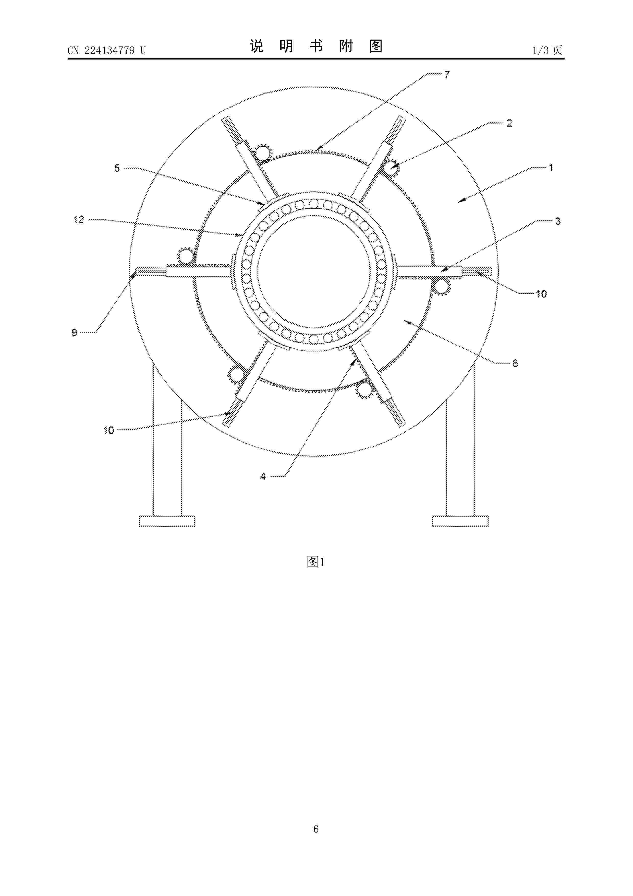
Resumen de: CN224134779U
本实用新型涉及轴承加工技术领域,公开了一种风力发电机轴承润滑装置,包括固定台,所述固定台的前端沿圆周方向设有若干驱动轮,所述驱动轮与所述固定台转动连接,所述驱动轮的一侧设有滑动杆,所述滑动杆与所述固定台的前端壁面滑动连接,所述滑动杆的前端均指向由所述驱动轮围成的圆的圆心,所述滑动杆的一侧设有与驱动轮相啮合的矩形齿条,所述滑动杆的前端设有夹紧头,所述固定台上设有带动所述驱动轮同步转动的驱动组件,本装置通过滑动杆前端的夹紧头对轴承外壁进行夹持,呈环形分布的滑动杆会将不同大小的轴承牢牢卡紧在固定台的中心位置,从而完成对不同大小的轴承的有效固定,方便对其加注润滑油进行润滑。

Resumen de: CN224134769U
本实用新型提供了一种车载无叶片风力发电补能设备,包括:迎风罩、振动转换组件、连接件、发电机组件、调节组件和固定组件;迎风罩包括上迎风罩和下迎风罩,连接件设置于上迎风罩与下迎风罩之间,调节组件设置于连接件的下端,固定组件设置于调节组件的下端,发电机组件设置于固定组件的上端,振动转换组件固定于所述上迎风罩上,且设置于发电机组件的上端,与发电机组件连接;调节组件用于将迎风罩产生的风致诱导振动滤后传递给振动转换组件,带动振动转换组件转动,通过发电机组件将风致诱导振动产生的机械能转换为电能。本实用新型利用风致诱导振动产生的机械能转变为电能,提升了补电设备的环境适用性,降低了其体积和占用面积。
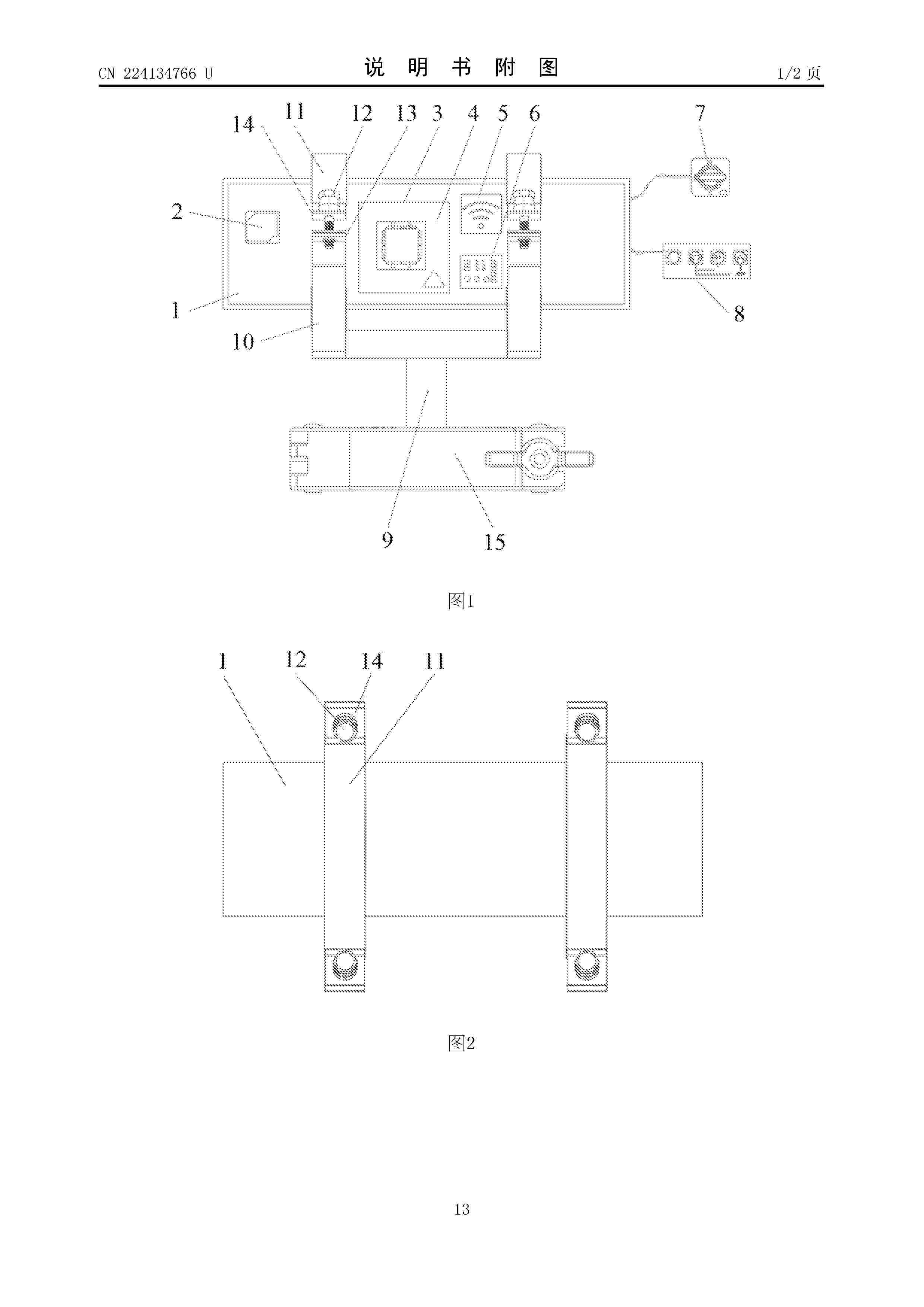
Resumen de: CN224134766U
本申请涉及风力发电技术领域,提供了一种新能源风电场电路稳定控制装置,包括控制箱、锁固结构和基座,控制箱的内部固定有电源模块、控制板、主芯片、通讯模块和串口,控制板位于电源模块的一侧,主芯片设于控制板的中心区域,通讯模块和串口设于控制板远离电源模块的一侧,控制箱的外部设有电路模块,电路模块位于通讯模块和串口远离控制板的一侧;锁固结构包括锁固座和锁固架,锁固座设于控制箱的底部外围区域,锁固架设于控制箱的顶部外围区域,锁固架与锁固座通过紧固结构固定连接;基座设于控制箱及锁固结构的底部,用于支撑控制箱和锁固结构。如此设置,增强了装置的抗干扰能力,减少了信号传输过程中的干扰,确保了电路的稳定运行。
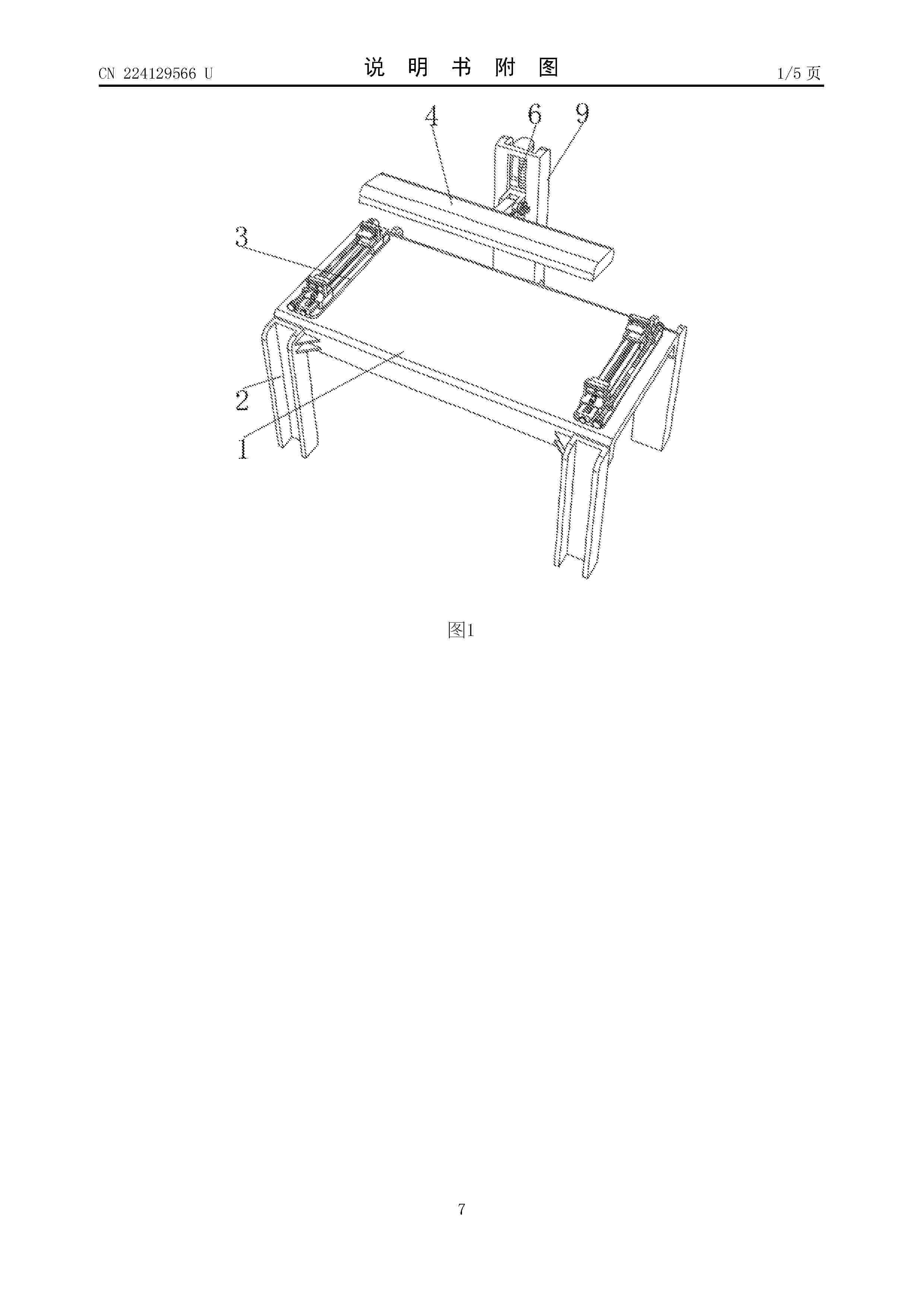
Resumen de: CN224129566U
本实用新型涉及风机叶片检修技术领域,公开了一种风机叶片检修装置,包括检修台,所述检修台上端的两边均固定连接有固定架,所述固定架上端两边均滑动连接有夹持架,两个所述夹持架的上端均固定连接有安装架,两个所述安装架的内部均滑动连接有夹持板,两个所述安装架的中部均转动连接有一号丝杆,两个所述一号丝杆的外表面分别与两个所述夹持板的中部螺纹连接,两个所述夹持架的内部均设置有调节机构。本实用新型可让装置在控制夹持板进行夹持工作时,仅需通过转动一号旋钮即可带动两边的夹持板进行同时移动,用于对叶片进行夹持工作,此方法可有效地降低在对叶片检修工作时的重复劳动,提高风机叶片检修的效率。
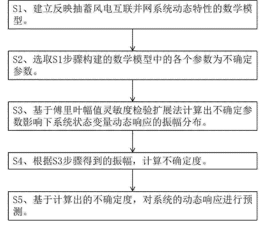
Resumen de: CN121886612A
本发明涉及非线性动力系统不确定分析技术领域,尤其涉及一种不确定参数影响下抽蓄风电互联并网系统动态响应的预测方法;包括以下步骤:S1、建立反映抽蓄风电互联并网系统动态特性的数学模型;S2、选取S1步骤构建的数学模型中的各个参数为不确定参数;S3、基于傅里叶幅值灵敏度检验扩展法计算出不确定参数影响下系统状态变量动态响应的振幅分布;S4、根据S3步骤得到的振幅,计算不确定度;S5、基于计算出的不确定度,对系统的动态响应进行预测;为系统开展不确定性分析和性能优化时提供重要理论依据。
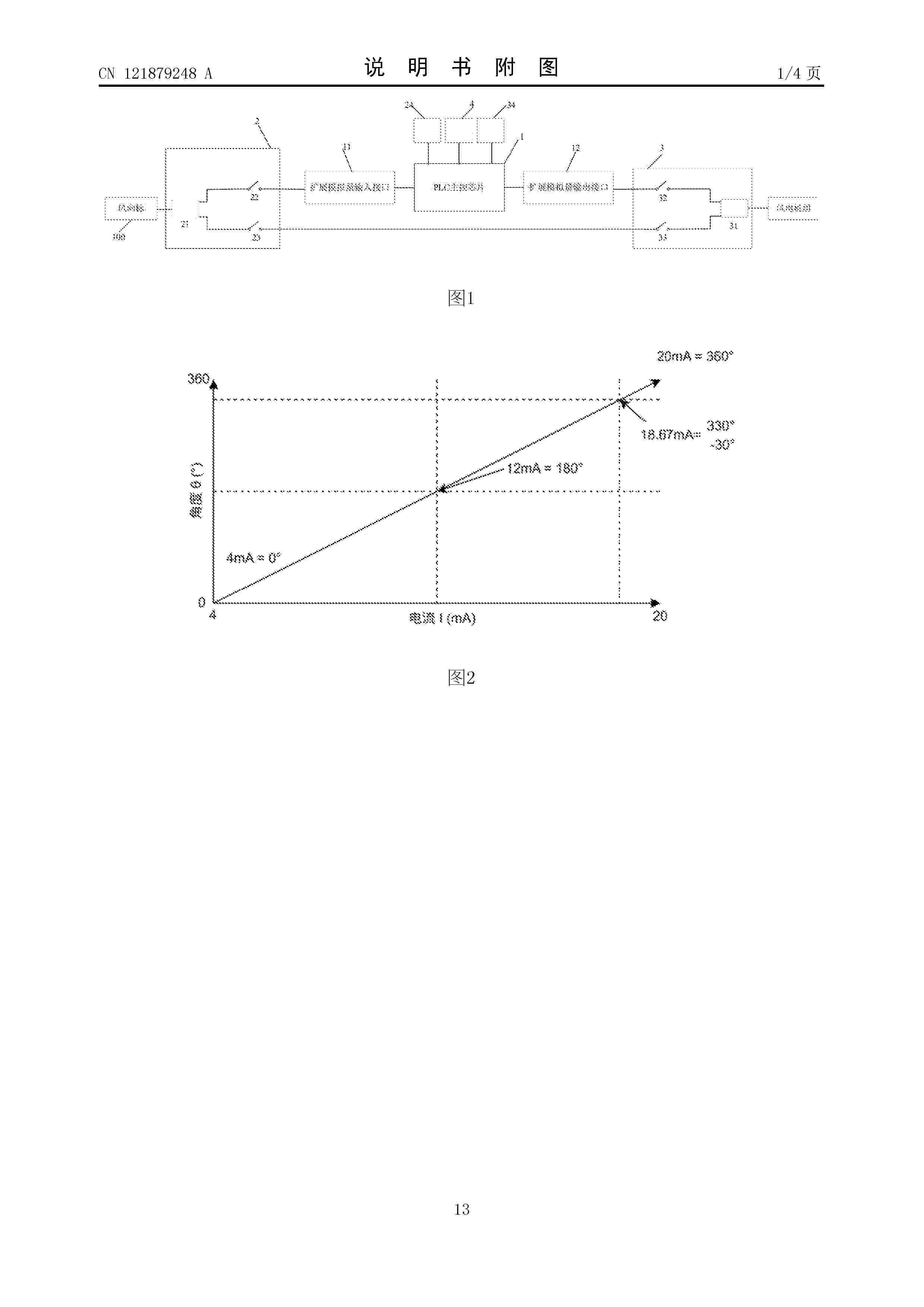
Resumen de: CN121879248A
本发明提出一种风向信号采集与输出偏航验证控制装置、方法及控制柜,通过扩展模块构建独立闭环,实时采集并处理风向标原始信号,输出修改后的模拟信号至风机主控,实现非侵入式验证。采用双电磁继电器构建硬件安全旁路:当PLC正常工作时,信号经程序处理后输出;当PLC故障或断电时,继电器自动复位,将原始风向信号无扰切换并直通输出至风机,从根本上保障了风机运行安全与验证系统的绝对可靠性。通过本发明,能够构建本质安全的硬件级故障旁路机制,确保在验证装置自身故障时,风机能自动、无扰地恢复至接收原始风向信号的状态,绝对保障风机运行安全。
Resumen de: CN121875902A
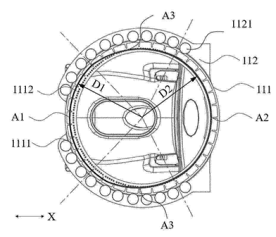
本申请涉及一种机架及风力发电机组,机架包括底座以及轴承座,底座包括底座本体以及设置于底座本体上的支撑体,底座本体包括用于与风力发电机组的偏航组件相连的法兰,轴承座设置于支撑体背离底座本体的一侧,轴承座包括轴承座本体以及沿第一方向间隔分布于轴承座本体内的第一轴承安装部和第二轴承安装部。支撑体包括第一支撑壁以及第二支撑壁,第一支撑壁支撑于第一轴承安装部且其在法兰的连接位置形成第一连接区,第二支撑壁支撑于第二轴承安装部且其在法兰的连接位置形成第二连接区,第一连接区和第二连接区在第一方向相对经过法兰的中心的垂直面非对称设置。本申请实施例中的机架,能够优化机架至偏航组件的传力路径,提高传力的可靠性。
Resumen de: CN121875915A
本发明提供了一种风力发电机立柱清理装置及其方法,风力发电机立柱包括柱体,设置在柱体上,用以承接叶片的基座。装置包括套设在柱体上的承接机构,与承接机构相连接的刮拭机构,所述刮拭机构构造成允许和柱体相互抵接在一起,并能够沿着由承接机构构成的路径运动,以对柱体进行刮拭。同时,装置还包括设置在基座上的卷收机构,以及与卷收机构相连接的拉索,所述拉索允许和承接机构相对固定在一起,以在卷收机构的作用下带动承接机构、刮拭机构沿着柱体轴向运动。通过这种方式,使得在卷收机构、承接机构、刮拭机构的相互配合下能够对柱体沿着周向以及轴向进行刮拭清理。由此,能够提高清洁效率,并还能够对其均匀清洁。
Resumen de: CN224134776U
本实用新型涉及风力发电领域,尤其涉及一种用于海上风电机组叶片防雷导线导通性检测的装置,包括:连接杆,两端分别设有转轮和翻转夹臂;拉绳,一端缠绕在转轮上,另一端与翻转夹臂连接;检测头,设置在翻转夹臂上,检测头通过测量导线与测量仪器连接;当转轮转动时,拉绳拉动翻转夹臂夹持叶片,使检测头接触叶片的接闪器。本实用新型针对目前存在的安全风险及经济成本较高的情况,提出更高效、更便携的检测装置,操作人员在塔基平台即可完成设备组装及测试,无需船舶配合,且机舱无需操作人员,降低人员操作风险。
Resumen de: CN224134705U
本实用新型属于PEM制氢资源再利用技术领域,具体涉及一种基于PEM系统的氧能调度自供电装置,包括:输入端管路通过流体控制阀一与PEM电解制氢系统的氧气排放管路连接的流体高压缓存装置,以及与所述PEM电解制氢系统的供电系统电连的储电装置,所述储电装置还电连有涡轮发电装置;所述流体高压缓存装置的输出端管路通过流体控制阀二连通所述涡轮发电装置。本实用新型通过对PEM制氢系统产生的高压氧气进行储存,再利用其可控制的排放,带动涡轮发电装置的涡轮转动,以实现与其轴接的发电机运行而发电,最终通过与涡轮发电装置电连的储电装置进行储电,以为PEM电解制氢系统的运行提供辅助供电,从而有效节约能耗。
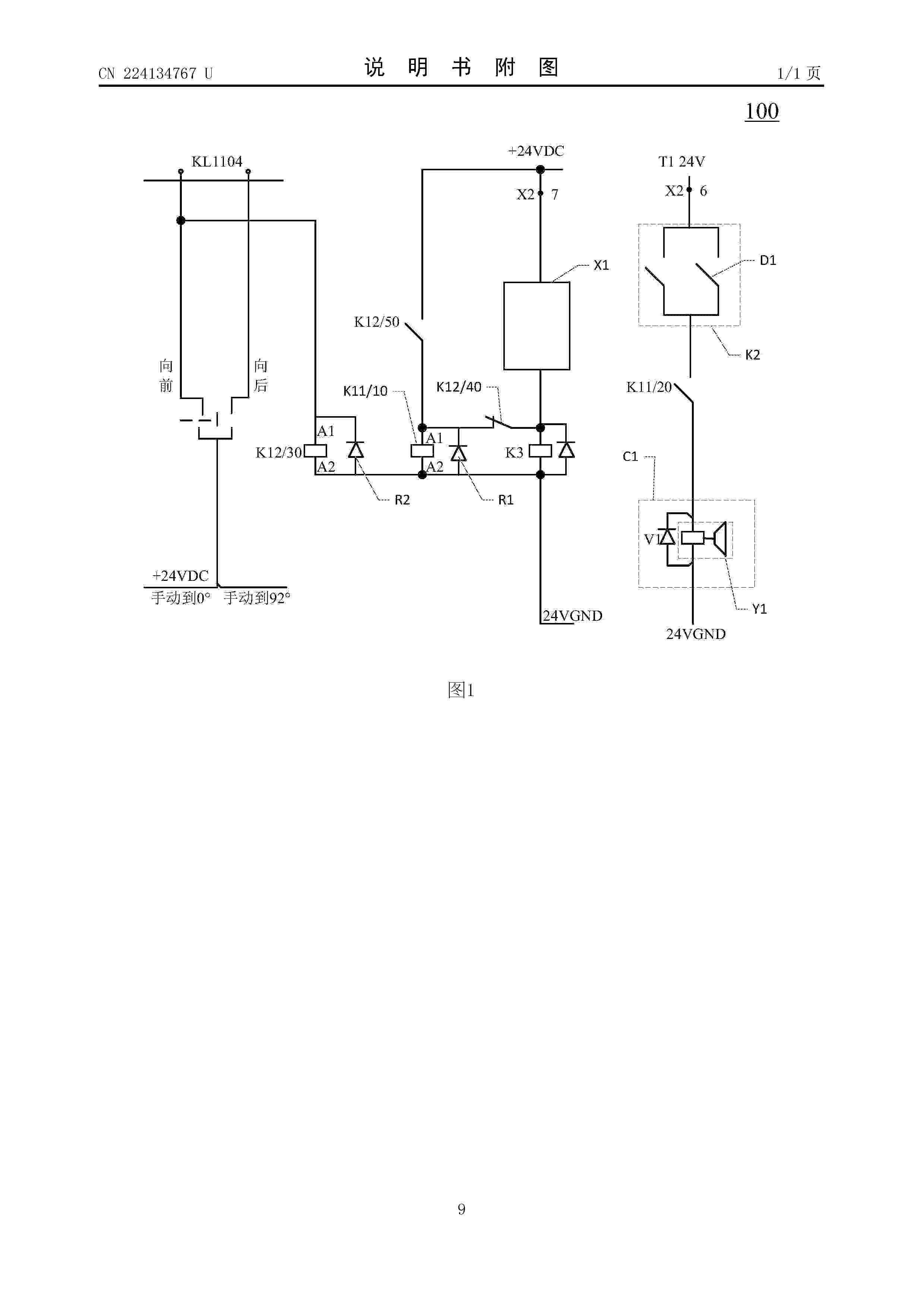
Resumen de: CN224134767U
本公开涉及一种变桨电机电磁刹车回路及风力发电机组变桨系统,包括:第一继电器、第二继电器、第三继电器、变桨电机电磁刹车、第一限位开关,变桨电机电磁刹车与第一限位开关分别连接至变桨变频器不同的端子排;第二继电器与第一限位开关串联,第三继电器与第二继电器并联,第二继电器与第三继电器被配置为由第一限位开关同步控制;第一继电器包括两组辅助触点,第一继电器的两组辅助触点分别与变桨电机电磁刹车串联,两组辅助触点并联。如此,可降低第一继电器引起的变桨故障率,同时增加安全回路,杜绝齿形带拉断的风险。
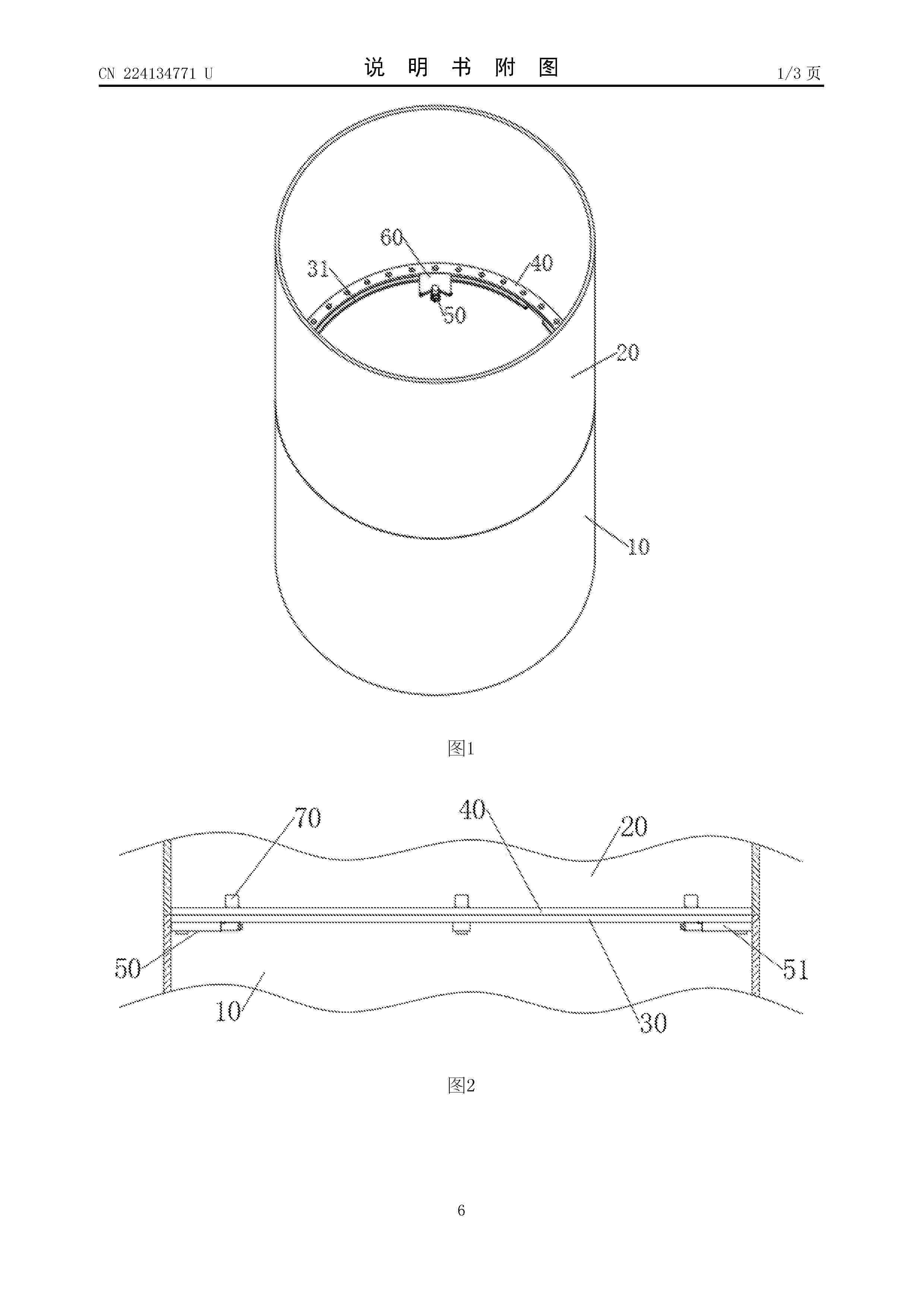
Resumen de: CN224134771U
本实用新型涉及风电塔筒技术领域,具体涉及一种风电塔筒卡槽防脱滑块结构,包括若干滑动机构,若干所述滑动机构设置有塔筒体一与塔筒体二,所述塔筒体一内部固定连接有法兰环一,所述塔筒体二内部固定连接有法兰环二,所述滑动机构包括定位块,所述定位块滑动连接有限位块,所述限位块顶部转动连接有限位杆。本实用新型中,通过定位板开设有V形槽,可先使滑动机构沿法兰环一底部滑动,调整滑动机构与限位杆的位置,可使限位杆向V形槽移动,使限位杆抵在定位板内部,对定位板与法兰环二进行限位,尽量防止筒体二位移脱离筒体一的范围,有利于降低筒体二的晃动,进而有利于将筒体二与筒体一尽量对齐。
Resumen de: CN121875511A
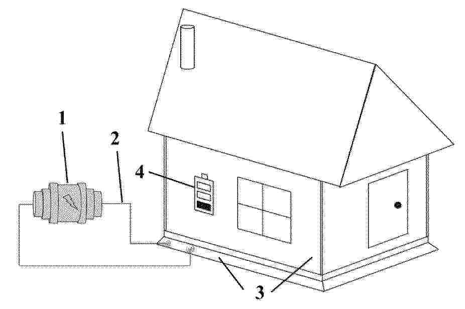
本申请是关于一种建筑储能一体化的住宅及其制备方法,住宅包括对所在建筑具有结构支撑作用的水泥基储能器件,该储能器件与外部电能和住宅内的用电设备通过导线连接;储能器件的制备方法包括:制备水泥基打印浆料,装入3D打印装置,逐层堆积形成打印体,固化养护、修整、干燥后,浸入可溶性碱/盐溶液中,得到水泥基电解质;在电极表面滴加可溶性碱/盐溶液,然后将电极与水泥基电解质叠合组装后密封包装,得到水泥基储能器件;水泥基电解质的打印层间界面具有定向排布的孔结构,孔径为0.5~20μm,孔隙率为10%~50%,孔结构的孔朝向与电极间的离子迁移方向一致。本申请提供的住宅具备较强的本体储能与自主供能的能力。
Resumen de: CN121875896A
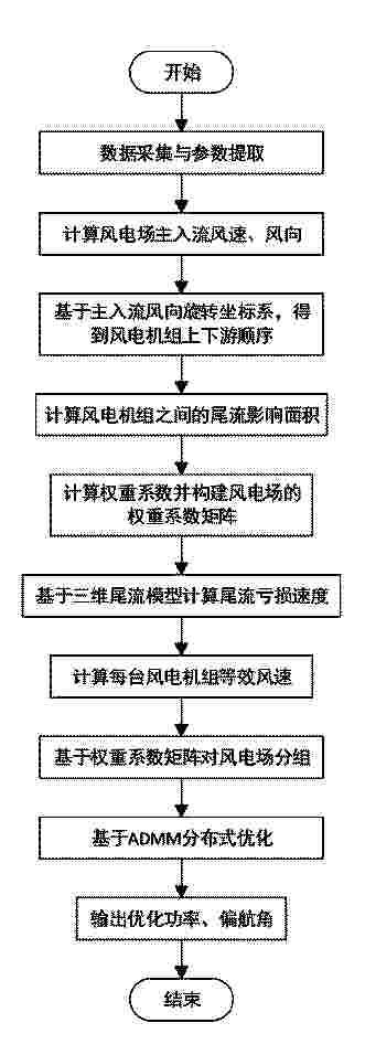
本发明公开了一种融合三维解析尾流模型及动态分组的ADMM分布式偏航控制方法、系统、计算机及存储介质,提取风电场布局及风电机组参数;以风速为模值、风向为角度构建风速风向向量,计算每台风电机组的风速风向向量在笛卡尔坐标系中的坐标分量,并计算风电场主入流的风速和风向;基于尾流叠加面积和风电机组之间的间距计算尾流权重系数,并构建尾流权重系数矩阵;基于三维解析尾流模型和尾流叠加模型,计算每台风电机组的等效风速,进而计算风电机组的功率;结合权重系数矩阵,对风电场内的全部风电机组分组;基于ADMM优化方法,以最大化功率为目标,优化每一个分组中风电机组的偏航角。本发明提高了风电场发电效益的同时提升优化效率。
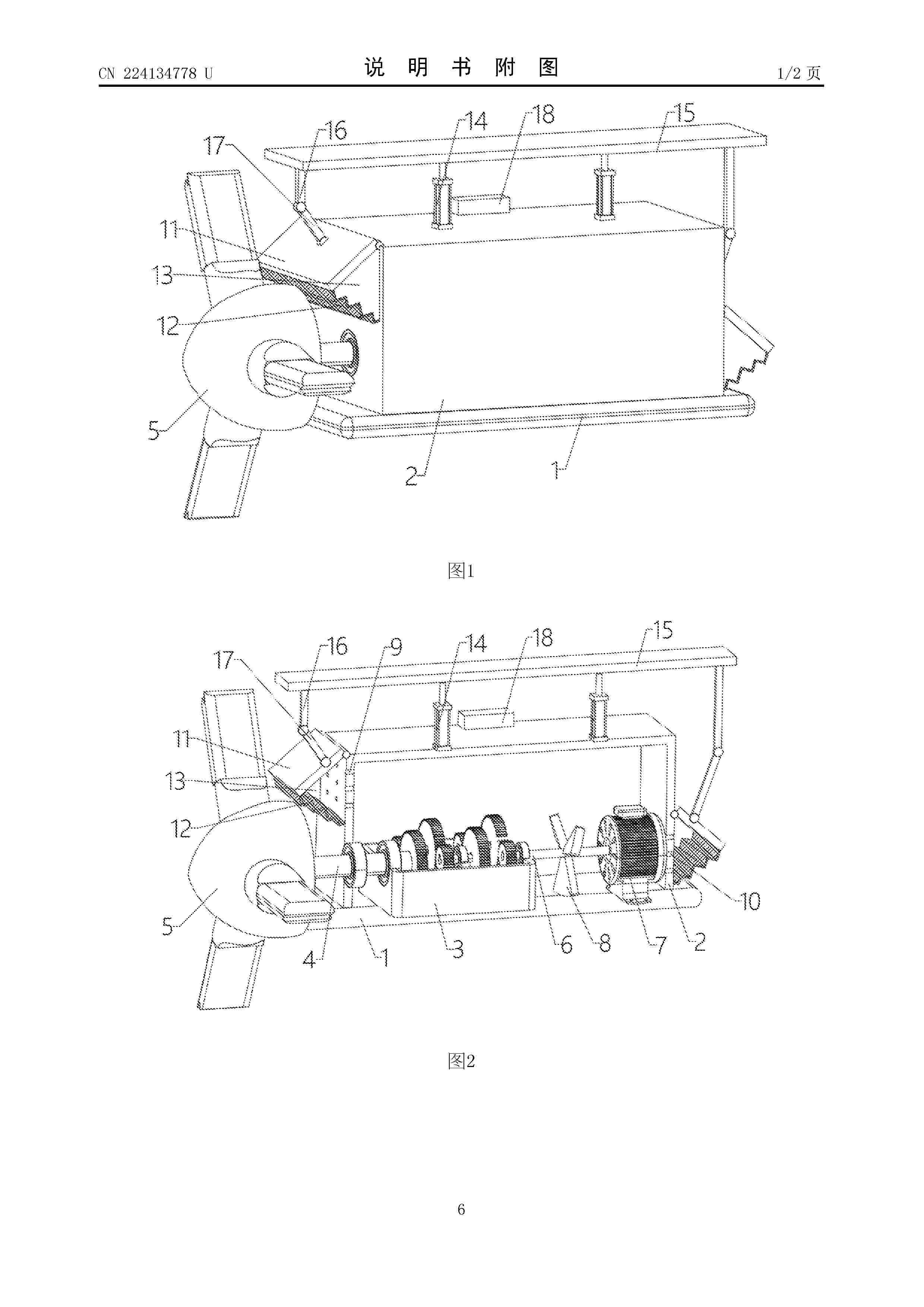
Resumen de: CN224134778U
本实用新型涉及风力发电技术领域,具体涉及一种风力发电机组散热装置,包括:底座,所述底座上端密封固定连接有机舱,所述机舱内安装有齿轮箱,所述机舱内安装有发电机,所述齿轮箱一侧通过输入轴安装有风轮件,所述齿轮箱另一侧通过输出轴与发电机连接;散热机构,所述散热机构包括固定连接在输出轴侧壁的多个叶轮。本实用新型设置散热机构,当外界下雨时,此时雨量传感器感应到外界下雨的信号,此时会通过外界控制机构控制两个电动推杆收缩,使得横板带动两个第一杆下移,进而两个第一杆通过两个第二杆带动两个防护板向下转动,对多个进风口和多个出风口处倾斜遮挡,避免外界雨水通过多个进风口和多个出风口进入机舱内。
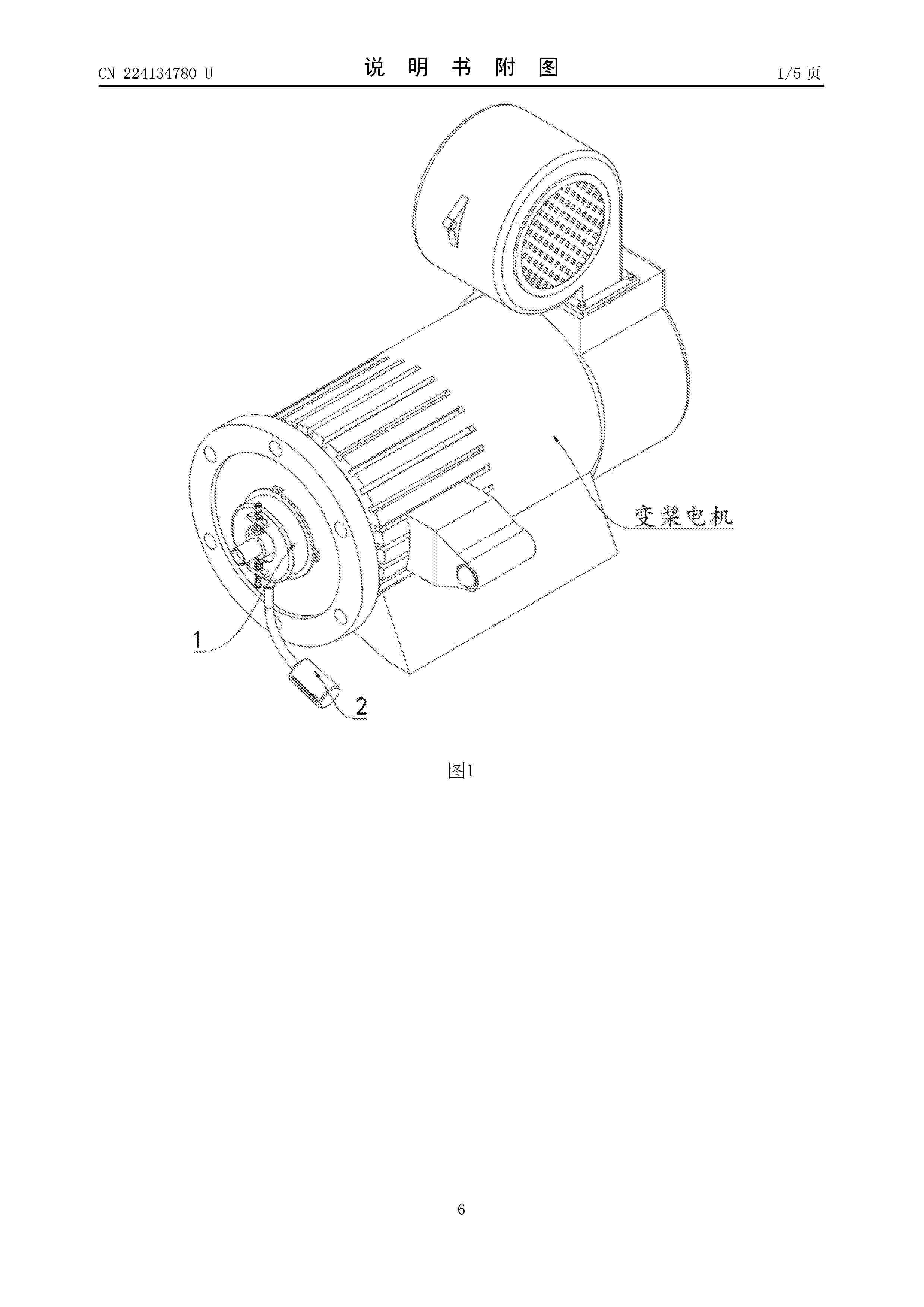
Resumen de: CN224134780U
本实用新型涉及变桨电机技术领域,尤其为一种防漏油罩,包括防漏油结构安装与变桨电机外表面,所述防漏油结构包括磁吸套环和金属密封垫;所述磁吸套环的内壁固定安装有锥形环,所述磁吸套环的外表面一侧固定安装有两个固定座,所述磁吸套环的内部开设有通孔,通过防漏油结构,在将防漏油结构固定在变桨电机上时,通过将磁吸套环套在输出轴外部并吸附在电机外表面,此时通过分别转动转把,使其转动,由于两侧限位杆的限位,可使螺纹杆推动安装座移动将输出轴夹持,由此可在电机工作时不妨碍输出轴的转动,同时由于锥形环的设置,可使润滑油停留在磁吸套环内部,而避免电机内部的润滑油从通孔处甩出,由此达到了防止变桨电机漏油的目的。
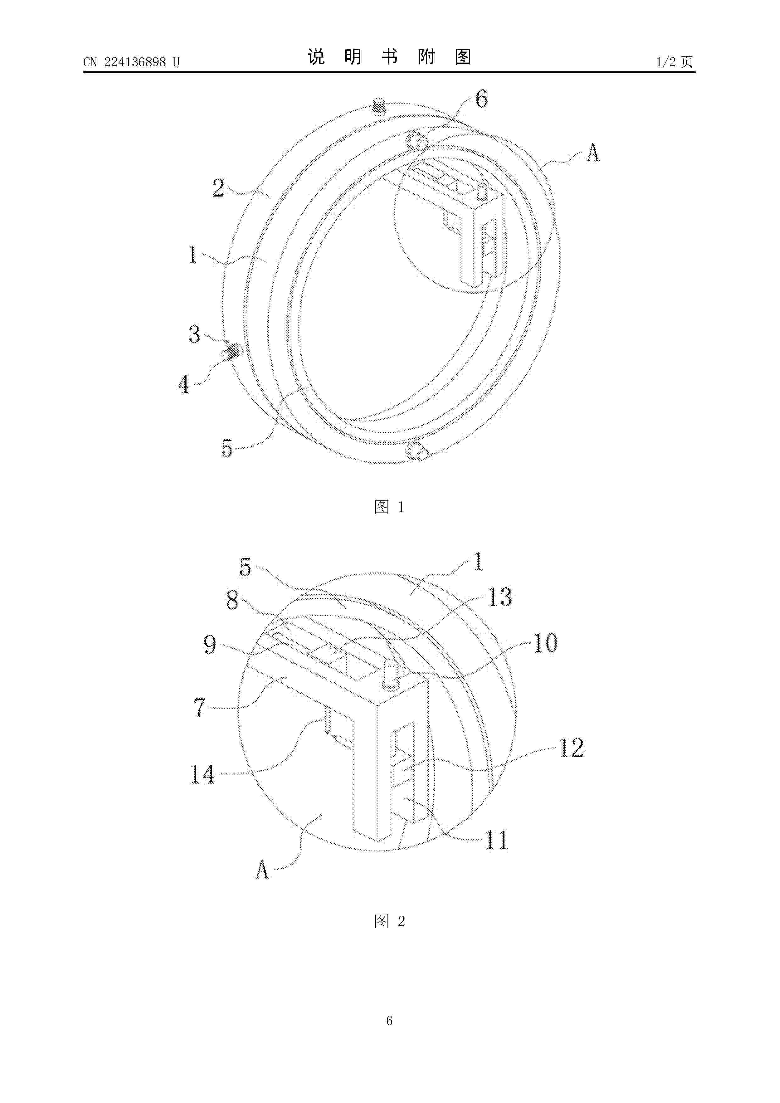
Resumen de: CN224136898U
本实用新型提供一种变桨轴承开裂预警装置,包括固定座,所述固定座的边侧固定有限位座,所述限位座上焊接有螺纹座,所述螺纹座的内部转动安装有螺纹柱,所述固定座的内部转动安装有环座,所述环座的内壁上焊接有固定架,所述固定架上分别开有固定槽和开槽,所述固定槽的内部活动安装有固定块,所述开槽的内部活动安装有活动块,所述活动块和固定块上均活动安装有探针。该一种变桨轴承开裂预警装置,在使用时固定块和活动块上的探针分别与轴承的固定环和转动环相接触,通过探针实现轴承的全面检测,在检测时探针前后移动完成对轴承的全面快速检测。
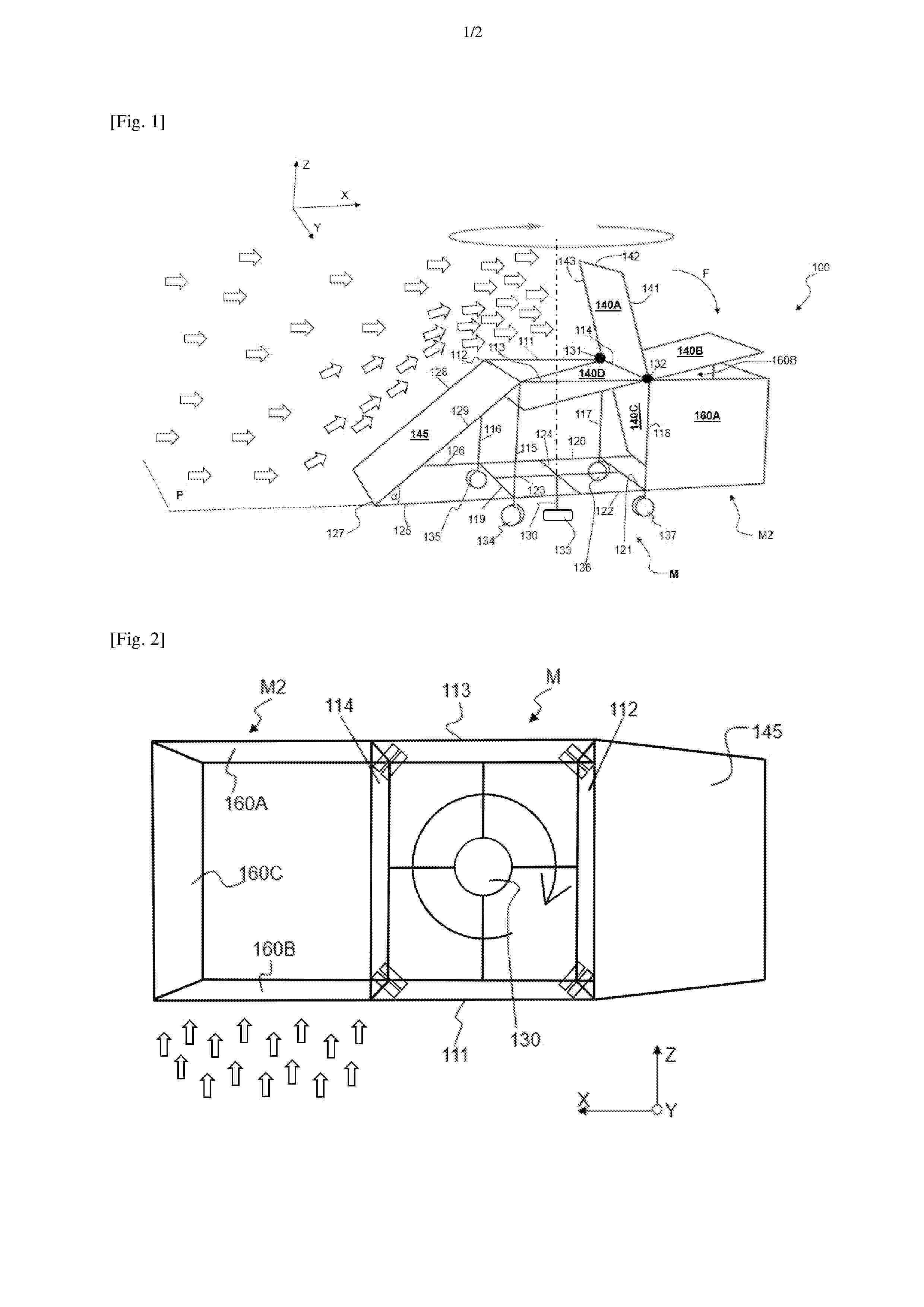
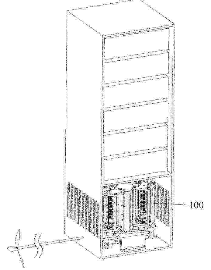
Resumen de: FR3167410A1
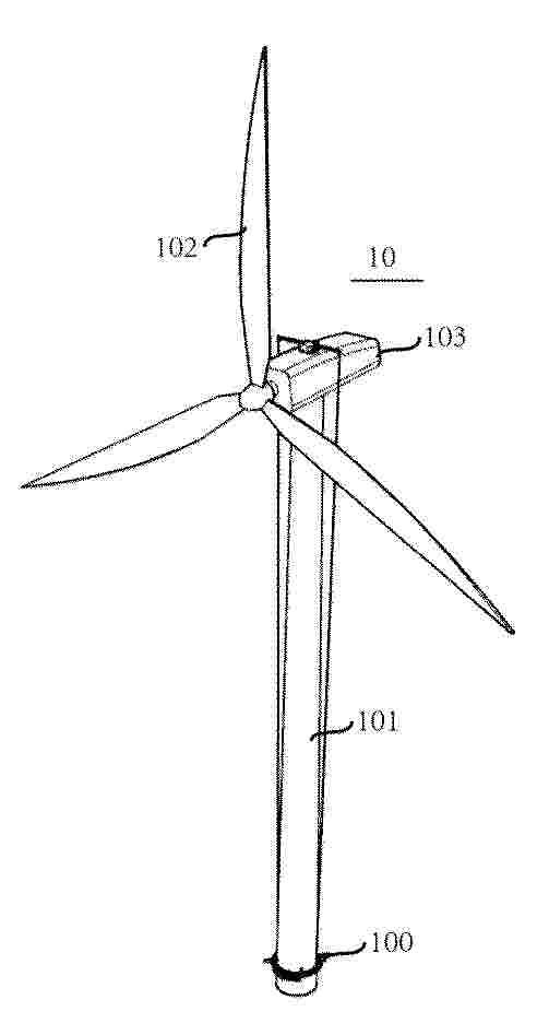
L’invention concerne une éolienne (100) modulaire à axe horizontal de rotation (114), comprenant au moins deux pales (140A, 140B, 140C, 140D) solidaires dudit axe horizontal de rotation et régulièrement espacées les unes par rapport aux autres, ladite éolienne (100) étant caractérisée en ce qu’elle comprend au moins un premier module (M) présentant une ossature cubique, une arête supérieure de ladite ossature cubique (M) formant ledit axe horizontal de rotation (114). Figure de l’abrégé : Fig 1
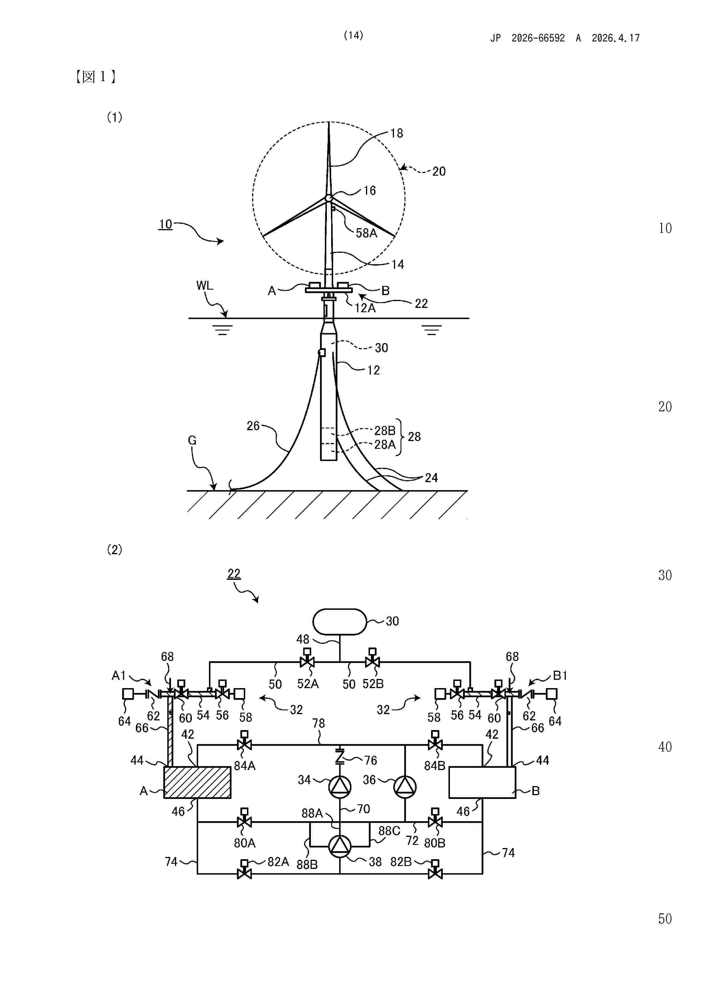
Resumen de: JP2026066592A
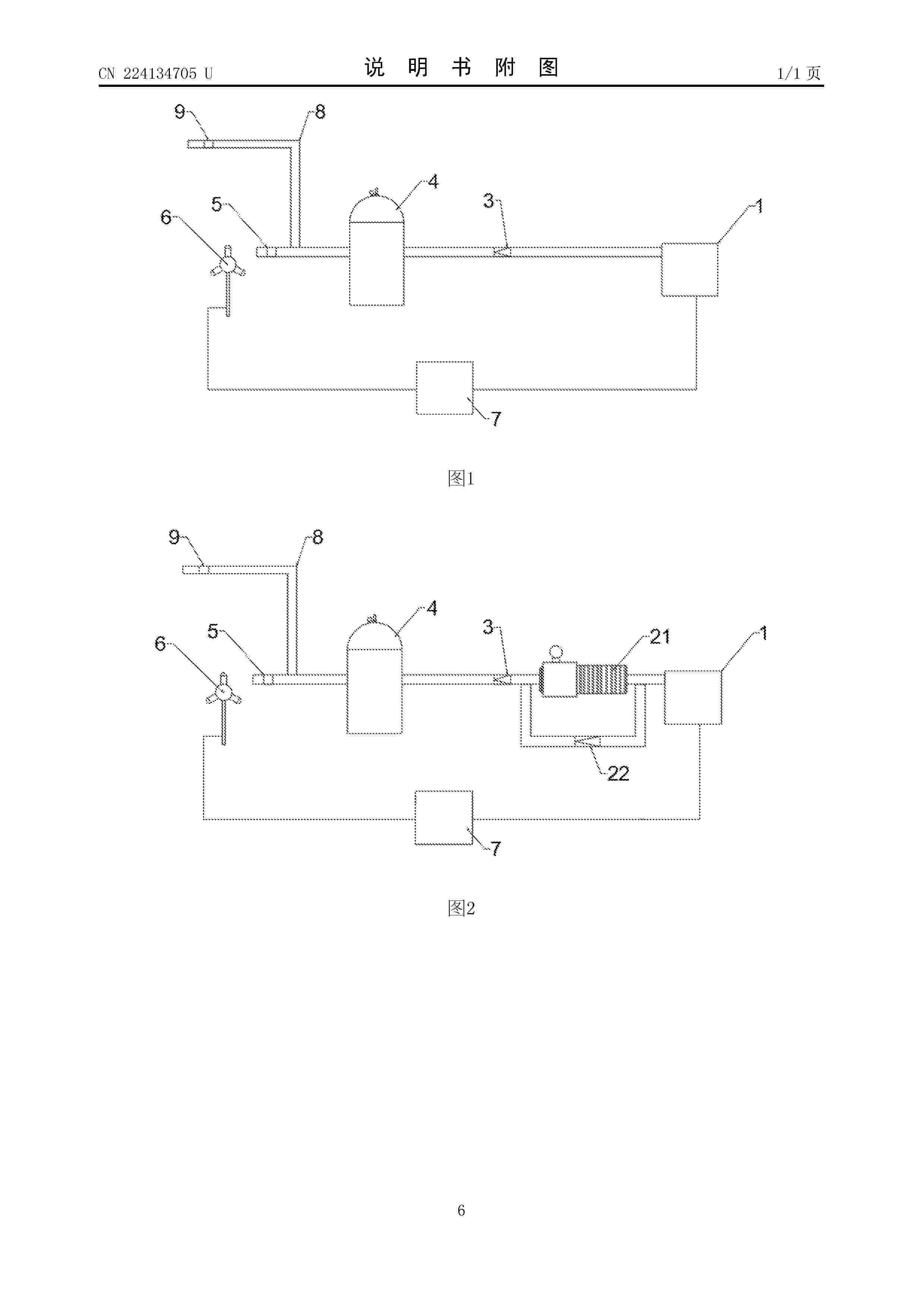
0001 【課題】洋上風力発電に適した設置、運用が可能な蓄電装置を備えた洋上風力発電設備を提供する。 【解決手段】洋上風力発電設備10であって、蓄電装置22は、圧縮空気を蓄えるエアタンク30と、連通先をエアタンク30と大気のいずれか一方に切り換え可能に設けられ、水と空気を混合して貯留可能な一対のタンク40と、大気に連通したタンク40から、もう一方のタンク40内に水を供給して水面を上昇させ、このタンク40内の空気を等温圧縮する空気圧縮手段34と、エアタンク30から圧縮空気をタンク40内に供給して水面を下降させ、このタンク40内の圧縮空気を等温膨張させてタンク40内の水を加圧し、加圧した加圧水の水力エネルギーを用いて水力発電を行う水力発電手段38とを有し、エアタンク30は、基礎構造12の内部に形成されるようにする。 【選択図】図1
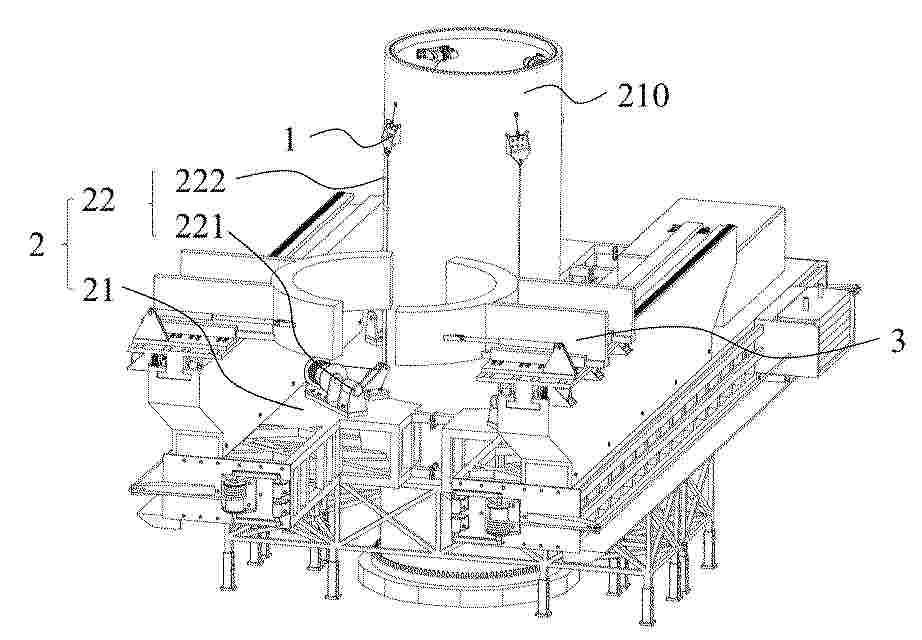
Resumen de: CN121872277A
本申请涉及一种风力发电机组的安装设备及安装方法,安装设备包括吊座、工装主体以及吊具主体,吊座连接于塔筒段的外壁面,工装主体包括安装平台以及设置于安装平台上的第一动力装置,第一动力装置包括第一驱动件以及第一牵引索,第一牵引索与吊座相连,第一驱动件用于收放第一牵引索,并使安装平台沿第一方向升降设置,吊具主体连接于安装平台并能够随安装平台移动,吊具主体用于夹取其中一个塔筒段或者风机部件,以使其中一个塔筒段安装至另一塔筒段上或者使风机部件安装至塔架上。本申请实施例中的风力发电机组,能够降低对吊具的性能要求,克服风力发电机组向高塔架、大容量发展的瓶颈,具有更广泛的应用前景。
Resumen de: CN121875897A
本发明涉及光伏发电领域,其公开了一种太阳能发电机节能装置,包括辅助蓄能构件,辅助蓄能构件包括安装架,安装架上设置有分配组件、蓄能组件以及扇轴,扇轴的输入端伸出至外界并设置有叶片,扇轴的输出端与分配组件的输入端连接,分配组件的输出端设置有多个且每个输出端均连接有一个蓄能组件,多个蓄能组件的输出端之间设置有发电机,蓄能组件包括底座、顶座以及用于两者连接的连接杆,底座与顶座之间安装有主丝杆与导杆,主丝杆与分配组件的输出端之间通过减速器实现动力连接,主丝杆的外部设置有升降件,升降件与导杆构成滑动连接,升降件与顶座之间设置有蓄能弹簧,底座与顶座之间安装有副丝杆,副丝杆与升降件构成螺纹连接。
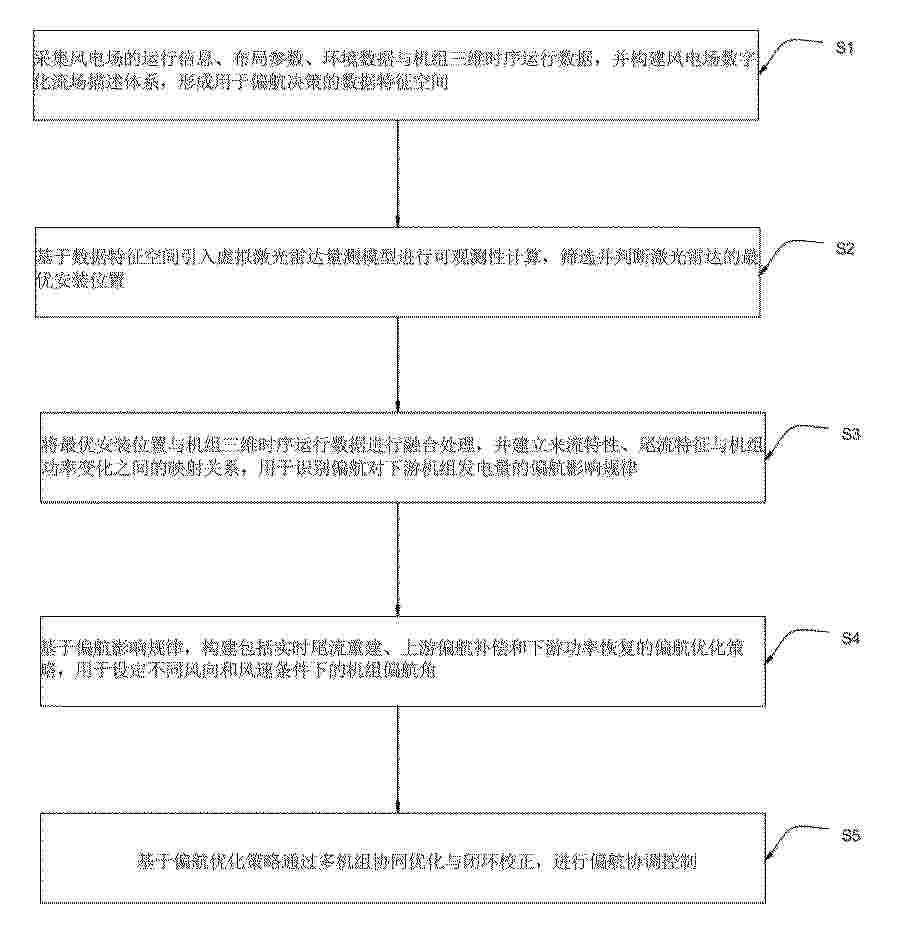
Resumen de: CN121875893A
本发明涉及风电场智能控制技术领域,具体地说,涉及一种适用于密集排布风电场的偏航优化方法。其包括以下步骤:采集风电场的运行信息、布局参数、环境数据与机组三维时序运行数据,并构建风电场数字化流场描述体系,形成用于偏航决策的数据特征空间;基于数据特征空间引入虚拟激光雷达量测模型进行可观测性计算,筛选并判断激光雷达的最优安装位置;将最优安装位置与机组三维时序运行数据进行融合处理。本发明通过构建融合空间拓扑、时间动态与环境敏感性的高维数字化流场特征空间,并结合虚拟激光雷达可观测性分析与尾流影响规律建模,能够精准识别上游机组偏航对下游机组功率的耦合影响。
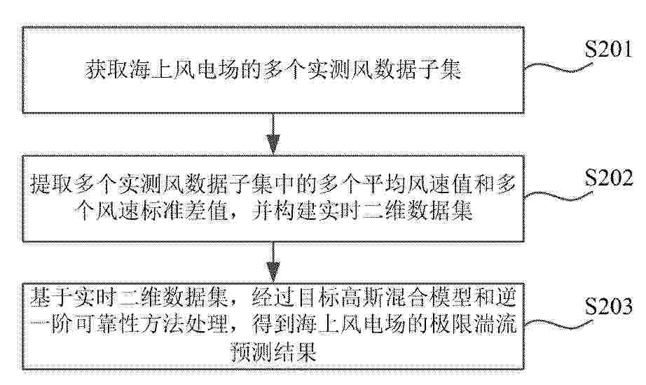
Resumen de: CN121880854A
本发明涉及海上风电技术领域,公开了一种极限湍流预测方法、装置、电子设备、介质及产品,该方法包括:获取海上风电场的多个实测风数据子集;提取多个实测风数据子集中的多个平均风速值和多个风速标准差值,并构建实时二维数据集;基于实时二维数据集,经过目标高斯混合模型和逆一阶可靠性方法处理,得到海上风电场的极限湍流预测结果,目标高斯混合模型用于拟合平均风速与湍流强度的联合概率分布。通过实施本发明,实现了精准、可靠的极限湍流预测,满足海上风电场应用需求。
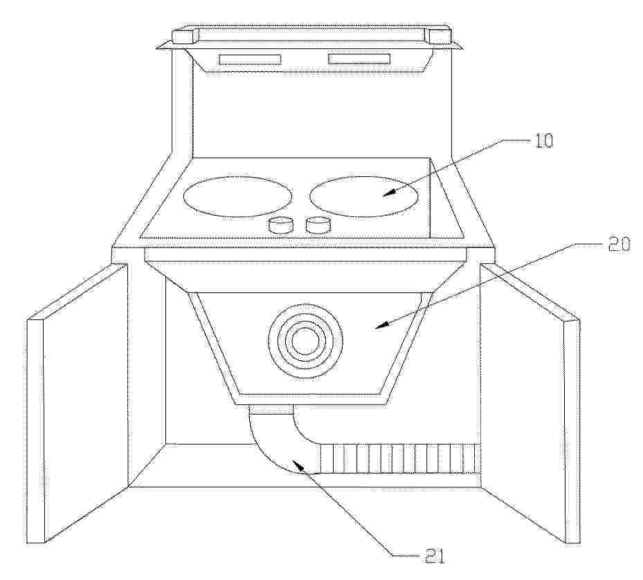
Resumen de: CN121876488A
本发明公开了一种具有主动散热功能的集成灶系统及其方法。该系统包括:灶具组件,包括燃烧器以及设置于燃烧器下方的玻璃面板;烟机组件,设置于玻璃面板的下方,具有用于抽排油烟的主风道;导流通道,设置于玻璃面板和主风道之间,其进风端位于玻璃面板下方以形成与外部空间连通的空腔,其出风端与主风道连通;其中,烟机组件工作时在主风道内产生负压,该负压驱动气流自外部空间经由空腔和导流通道流向主风道。本发明利用烟机组件现有的抽吸能力作为驱动力,使气流流经玻璃面板下方进行对流换热,在不影响油烟抽排功能的前提下实现玻璃面板的主动散热,有效降低玻璃面板温度,减少用户烫伤风险和变形隐患,提高集成灶的安全性能。
Nº publicación: CN121876122A 17/04/2026
Solicitante:
国网吉林省电力有限公司经济技术研究院吉林省长春电力勘测设计院有限公司大连理工大学
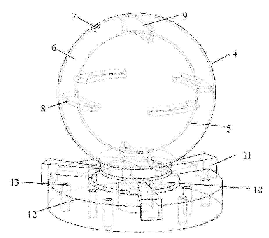
Resumen de: CN121876122A
一种电网侧储能协同的球壳夹层状三维晃液系统,属于减振设备技术领域,其布置于风力机组的塔筒中空内部,包括晃液舱和卡盘结构。晃液舱由晃液舱外壁与晃液舱内壁同心设置形成封闭夹层,围成晃液舱腔体室;晃液舱外壁设置有灌液口;晃液舱腔体室内部设有水平挡板和垂直挡板;晃液舱下部与晃液舱固定底座连接。本发明能够在多方向激励作用下形成稳定有效的晃液耗能,实现对塔筒低频、大位移低阶振动模态的有效匹配,适用于不同容量等级和结构特性的风力机塔筒;无需外部供能,适于长期稳定运行,工程适用性强;同时可通过抑制由结构振动诱发的机组运行波动,降低储能系统在风电并网平滑调节过程中的瞬时调节压力,提高风机运行稳定性和并网友好性。
 BOPI
BOPI
 Sede Electrónica