Ministerio de Industria, Turismo y Comercio LogoMinisterior
 

Alerta

Resultados 525 resultados
LastUpdate Última actualización 28/07/2026 [06:54:00]
pdfxls
Solicitudes publicadas en los últimos 15 días / Applications published in the last 15 days
previousPage Resultados 350 a 375 de 525 nextPage  

FUEL CELL CATALYST LIFETIME EXTENSION AND REFURBISHMENT

NºPublicación:  WO2026152089A1 16/07/2026
Solicitante: 
FC RENEW LLC [US]
FC RENEW, LLC
WO_2026152089_A1

Resumen de: WO2026152089A1

An approach is provided for fuel cell catalyst lifetime extension and refurbishment. The approach involves, for example, introducing a renewing agent into an assembled electrochemical stack (e.g., fuel cell stack). The approach also involves applying a first electrochemical potential to the electrocatalyst to induce dissolution of at least a portion of the electrocatalyst into the renewing agent. The approach further involves applying a second electrochemical potential to the electrocatalyst to induce redeposition of the dissolved electrocatalyst onto an electrode surface in a renewed distribution, thereby restoring catalytic activity and extending an operational lifetime of the assembled electrochemical stack.

MEMBRANE ELECTRODE ASSEMBLY

NºPublicación:  US20260204594A1 16/07/2026
Solicitante: 
TOYOTA JIDOSHA KK [JP]
TOYOTA JIDOSHA KABUSHIKI KAISHA
US_20260204594_A1

Resumen de: US20260204594A1

A membrane electrode assembly for a fuel cell includes, in this order, a cathode catalyst layer, a solid polymer electrolyte membrane, and an anode catalyst layer. The cathode catalyst layer contains at least a catalyst and a highly oxygen-permeable ionomer. At least one selected from the group consisting of the cathode catalyst layer, the solid polymer electrolyte membrane, and the anode catalyst layer contains a nitrogen-containing multidentate ligand coordinatable to an iron ion.

ELECTROLYTE MEMBRANE FOR HIGH-TEMPERATURE POLYMER ELECTROLYTE MEMBRANE FUEL CELL

NºPublicación:  US20260204608A1 16/07/2026
Solicitante: 
HYUNDAI MOTOR CO [KR]
KIA CORP [KR]
INDUSTRY ACADEMIC COOPERATION FOUNDATION GYEONGSANG NATIONAL UNIV [KR]
Hyundai Motor Company
Kia Corporation
INDUSTRY-ACADEMIC COOPERATION FOUNDATION GYEONGSANG NATIONAL UNIVERSITY
US_20260204608_A1

Resumen de: US20260204608A1

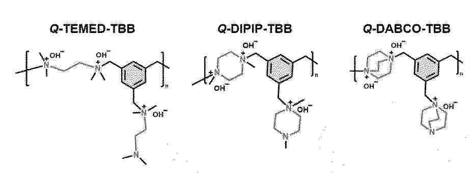
Disclosed are an electrolyte membrane for a high-temperature polymer electrolyte membrane fuel cell including a polymer electrolyte having a novel structure with an ether group introduced therein, and a method of manufacturing the same.

Verfahren zum Temperieren eines Brennstoffzellensystems und Brennstoffzellensystem für einen Flugantrieb

NºPublicación:  DE102025101402A1 16/07/2026
Solicitante: 
MTU AERO ENGINES AG [DE]
MTU Aero Engines AG
DE_102025101402_PA

Resumen de: DE102025101402A1

Die Erfindung betrifft ein Verfahren (100) zum Temperieren eines Brennstoffzellensystems (10) eines Flugantriebs (2) eines Flugzeugs (1) sowie ein Brennstoffzellensystem (10) für einen Flugantrieb (2), oder für ein Flugzeug (1) mit einem Flugantrieb (2). Das Brennstoffzellensystem (10) umfasst ein Temperiersystem (20) und ein separates Heizsystem (50), um das Brennstoffzellensystem (10) auch bei sehr niedrigen Systemtemperaturen (T), die unterhalb eines ersten Schwellenwerts (T1) liegen, aufheizen zu können. Das Heizsystem (50) kann dabei bei Bedarf an das Temperiersystem (20) des Brennstoffzellensystems (10) angeschlossen werden.

FUEL CELL

NºPublicación:  US20260204598A1 16/07/2026
Solicitante: 
SUBARU CORP [JP]
SUBARU CORPORATION
US_20260204598_A1

Resumen de: US20260204598A1

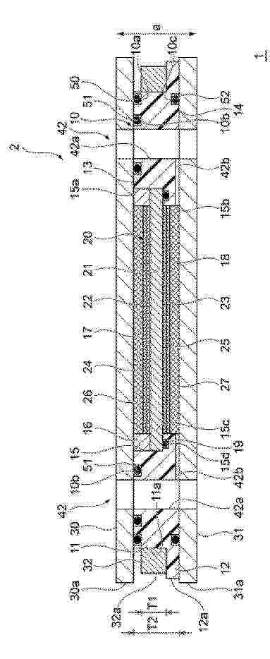
A fuel cell at least includes a first separator, a first gasket, a sub-gasket, a membrane electrode assembly, a second separator, and a second gasket that are stacked together. One or each of the first separator and the second separator is a flow-channel separator. The fuel cell further includes a tension applier disposed outward with respect to an end portion of the first gasket and configured to apply a tension to the sub-gasket to press the sub-gasket against the first gasket in a region in which a surface pressure applied to the sub-gasket by the flow-channel separator is relatively low.

液体分離デバイスおよび使用方法

NºPublicación:  JP2026523941A 16/07/2026
Solicitante: 
ポール・コーポレーション
JP_2026523941_A

Resumen de: WO2025006137A1

A liquid separator device, a method of using the liquid separator device, and a system including at least one liquid separator device, are disclosed.

CARBON DIOXIDE CAPTURE SYSTEM FOR FUEL CELL SYSTEM

NºPublicación:  WO2026151183A1 16/07/2026
Solicitante: 
HD KOREA SHIPBUILDING \uFF06 OFFSHORE ENG CO LTD [KR]
\uC5D0\uC774\uCE58\uB514\uD55C\uAD6D\uC870\uC120\uD574\uC591 \uC8FC\uC2DD\uD68C\uC0AC
WO_2026151183_A1

Resumen de: WO2026151183A1

A carbon dioxide capture system for a fuel cell system, according to the present invention, comprises: a moisture separator for separating moisture from the fuel electrode exhaust gas discharged from a fuel electrode of a fuel cell stack comprising the fuel electrode (anode), to which a fuel is supplied, and an air electrode (cathode) to which air is supplied; a carbon dioxide capture device for capturing carbon dioxide from the fuel electrode exhaust gas from which moisture has been separated by the moisture separator; a carbon dioxide capture line connected to the carbon dioxide capture device after passing the moisture separator from the fuel electrode of the fuel cell stack; and a hydrogen recycle line for distributing, to the fuel electrode of the fuel cell stack and a post-combustor, the hydrogen gas separated out after carbon dioxide was captured by the carbon dioxide capture device.

FUEL CELL

NºPublicación:  US20260204596A1 16/07/2026
Solicitante: 
SUBARU CORP [JP]
SUBARU CORPORATION
US_20260204596_A1

Resumen de: US20260204596A1

A fuel cell at least includes a first separator, a second separator, and a membrane electrode assembly. The first separator includes a corrugated structure configured to define a gas flow channel adjacent to the membrane electrode assembly and a cooling-water flow channel adjacent to the second separator. The gas flow channel and the cooling-water flow channel are alternately arranged. The corrugated structure includes corners. The gas flow channel and the cooling-water flow channel are partitioned from each other by a partition wall including a protruding portion protruding toward the gas flow channel from a reference line connecting a first corner vertex of one of the corners that is adjacent to the membrane electrode assembly and a second corner vertex of another one of the corners that is adjacent to the second separator. The protruding portion includes a third corner vertex.

Composite Proton Exchange Membrane Composition and Method of Preparation

NºPublicación:  US20260204607A1 16/07/2026
Solicitante: 
SAUDI ARABIAN OIL CO [SA]
Saudi Arabian Oil Company
US_20260204607_A1

Resumen de: US20260204607A1

0000 A method of preparing a membrane. The method includes: preparing an amino-functionalized polybenzimidazole (APBI) from precursors including a benzidine derivative, an aromatic dicarboxylic acid, and an aromatic carboxylic acid that includes an amino group substituent; preparing a perfluorosulfonic acid (PFSA) solution including a PFSA resin; adding the APBI to the PFSA solution to form a casting solution; pouring the casting solution onto a glass plate to form a layer of a casted solution on the glass plate; and drying the layer of the casted solution on the glass plate to form a membrane on the glass plate, the membrane including the APBI and the PFSA resin.

TAPERED, INTERDIGITATED CHANNELS FOR UNIFORM FLOW

NºPublicación:  WO2026151893A2 16/07/2026
Solicitante: 
THE BOARD OF TRUSTEES OF THE UNIV OF ILLINOIS [US]
THE BOARD OF TRUSTEES OF THE UNIVERSITY OF ILLINOIS
WO_2026151893_A2

Resumen de: WO2026151893A2

A fluid-flow device for providing uniform flow of a fluid is disclosed. The fluid-flow device includes a porous medium, a plurality of inlet channels, and a plurality of outlet channels interdigitated with the inlet channels and in fluid communication with the outlet channels via the porous medium. At least one of the inlet channels and one of the adjacent outlet channels are defined by an outer-boundary profile having a cross-sectional geometry that varies non-linearly along its length. A shortest flow path distance through the porous medium between the outer boundary profile of the inlet channel and the outer boundary profile of the outlet channel is constant. The fluid-flow device provides uniform flow of fluid through the device with improved efficiency.

METHOD FOR THE PREPARATION OF A GAS DIFFUSION LAYER USING CALENDERING AND A GAS DIFFUSION LAYER OBTAINABLE BY SUCH METHOD

NºPublicación:  WO2026149966A1 16/07/2026
Solicitante: 
AVANTIUM KNOWLEDGE CENTRE B V [NL]
AVANTIUM KNOWLEDGE CENTRE B.V.
WO_2026149966_A1

Resumen de: WO2026149966A1

The present invention relates to a method for preparing gas-diffusion layers comprising the steps of: combining a layer of supporting material, a layer of the adhesive composition and a layer of the carrier-binder paste into a layered structure; heating the layered structure to a temperature in the range of between equal to or more than 70 °C and equal to or less than 90 °C with a maximum average heating rate of 2.0 °C/min; followed by at least two calendering steps comprising calendering the layered structure at least once at a temperature in the range 90-110 °C; and calendering the layered structure at least once at a temperature of at least 150 °C; wherein each calendering step is carried out using a gap width of 0-0.5 mm smaller than the gap width used in an immediately preceding calendering step.

Verfahren und Vorrichtung zur Überprüfung des Oxidationsmittelförderers eines Brennstoffzellensystems

NºPublicación:  DE102025100811A1 16/07/2026
Solicitante: 
BAYERISCHE MOTOREN WERKE AG [DE]
Bayerische Motoren Werke Aktiengesellschaft
DE_102025100811_PA

Resumen de: DE102025100811A1

Die hier offenbarte Technologie betrifft erfindungsgemäß eine Vorrichtung (103) zur Überprüfung eines Brennstoffzellensystems (100), das einen Brennstoffzellenstapel (102) und einen Oxidationsmittelförderer (211) zur Förderung von Oxidationsmittel (201) für den Brennstoffzellenstapel (102) aufweist. Die Vorrichtung (103) ist eingerichtet, einen stationären Referenz-Arbeitspunkt des Brennstoffzellensystems (100) einzustellen, sodass eine Vielzahl von Betriebsparametern des Brennstoffzellensystems (100) jeweils einen vordefinierten Referenzwert für den jeweiligen Betriebsparameter aufweist, wobei die Vielzahl von Betriebsparametern eine Drehzahl eines Elektromotors des Oxidationsmittelförderers (211) umfasst. Die Vorrichtung (103) ist ferner eingerichtet, einen Messwert eines tatsächlich von dem Elektromotor aufgenommenen drehmomentbildenden Stroms zu erfassen, während das Brennstoffzellensystem (100) in dem stationären Referenz-Arbeitspunkt betrieben wird, und auf Basis des Messwertes des tatsächlich von dem Elektromotor aufgenommenen drehmomentbildenden Stroms zu bestimmen, ob der Oxidationsmittelförderer (211) eine Beeinträchtigung, insbesondere eine Schwergängigkeit, aufweist.

Verfahren zur Herstellung einer Bipolarplatte

NºPublicación:  DE102025101417A1 16/07/2026
Solicitante: 
BOSCH GMBH ROBERT [DE]
Robert Bosch Gesellschaft mit beschr\u00E4nkter Haftung
DE_102025101417_PA

Resumen de: DE102025101417A1

Verfahren zur Herstellung einer Bipolarplatte (10, 51) mit den Schritten: primäres mechanisches Umformen mit einem Umformwerkzeug (79, 80, 81, 82) der ersten Rohplatte (83, 85) zu einer ersten Platte (64, 85) als ein erstes Plattenelement (85) indem mit dem Umformwerkzeug (79, 80, 81, 82) auf die erste Rohplatte (83, 85) eine primäre Umformkraft aufgebracht wird und/oder primäres mechanisches Umformen mit einem Umformwerkzeug (79, 80, 81, 82) der zweiten Rohplatte (84, 86) zu einer zweiten Platte (65, 86) als ein zweites Plattenelement (86) indem mit dem Umformwerkzeug (79, 80, 81, 82) auf die zweite Rohplatte (84, 86) eine primäre Umformkraft aufgebracht wird, Stapeln des ersten Plattenelements (64, 85) und des zweiten Plattenelements (65, 86) aufeinander, so dass Innenseiten (66) des ersten und zweiten Plattenelements (85, 86) an einem Kontaktbereich (68) aufeinander liegen, Herstellen wenigstens einer Schweißverbindung (69, 70, 71, 72) zwischen dem ersten und der zweiten Plattenelement (85, 86), so dass die Bipolarplatte (10, 51) aus dem mit der Schweißverbindung (69, 70, 71, 72) miteinander verbundenen ersten und zweiten Plattenelement (85, 86) ausgebildet wird, wobei das erste Plattenelement (85) und/oder das zweite Plattenelement (86) zusätzlich sekundär umgeformt wird indem das erste und/oder zweite Plattenelement (85, 86) erwärmt wird zur Reduzierung der notwendigen sekundären Umformkraft und mit einer sekundären Umformkraft das sekundäre Umformen im erwä

FUEL CELL SYSTEM

NºPublicación:  US20260204602A1 16/07/2026
Solicitante: 
TOYOTA JIDOSHA KK [JP]
TOYOTA JIDOSHA KABUSHIKI KAISHA
US_20260204602_A1

Resumen de: US20260204602A1

0000 A fuel cell system includes a housing and a fuel cell disposed inside the housing. A gas discharge hole and a hydrogen detection sensor are provided at an upper portion of the housing in a state in which the housing is installed, and an outside air introduction hole is provided at a lower portion of the housing in the state in which the housing is installed.

Verfahren und Vorrichtung zum Diagnostizieren eines Brennstoffzellensystems, Brennstoffzellensystem, Fahrzeug, Computerprogrammprodukt und Speichermedium

NºPublicación:  DE102025100959A1 16/07/2026
Solicitante: 
BAYERISCHE MOTOREN WERKE AG [DE]
Bayerische Motoren Werke Aktiengesellschaft
DE_102025100959_PA

Resumen de: DE102025100959A1

Die hier offenbarte Technologie betrifft erfindungsgemäß ein Verfahren zum Diagnostizieren eines Brennstoffzellensystems (10), aufweisend: Ansteuern eines Ejektor-Injektors (28) zum impulsartigen Leiten von Brennstoff durch den Ejektor (18) zur Anode (12), Ermitteln eines Ejektor-Einlassdruckverhaltens (91) mittels einer Einlassdrucksensorik (31) und Ermitteln eines Ejektor-Differenzdruckverhaltens (92) mittels einer Differenzdrucksensorik (32), Ansteuern eines Bypass-Injektors (38) zum impulsartigen Leiten von Brennstoff durch den Bypasspfad (34) zur Anode (12), Ermitteln eines Bypass-Einlassdruckverhaltens (93) mittels der Einlassdrucksensorik (31) und Ermitteln eines Bypass-Differenzdruckverhaltens (94) mittels der Differenzdrucksensorik (32), und Diagnostizieren des Brennstoffzellensystems (10) basierend auf dem ermittelten Ejektor-Einlassdruckverhalten (91), basierend auf dem ermittelten Ejektor-Differenzdruckverhalten (92), basierend auf dem ermittelten Bypass-Einlassdruckverhalten (93) und/oder basierend auf dem ermittelten Bypass-Differenzdruckverhalten (94). Die Technologie betrifft ferner eine Vorrichtung, ein Brennstoffzellensystem (10), ein Fahrzeug (100) und ein Computerprogrammprodukt (50) zum Durchführen des Verfahrens sowie ein computerlesbares Speichermedium (60), auf welchem das Computerprogrammprodukt (50) gespeichert ist.

Verfahren und Steuervorrichtung zum Betreiben einer Brennstoffzellenvorrichtung und Brennstoffzellenvorrichtung

NºPublicación:  DE102025101467A1 16/07/2026
Solicitante: 
BOSCH GMBH ROBERT [DE]
Robert Bosch Gesellschaft mit beschr\u00E4nkter Haftung
DE_102025101467_PA

Resumen de: DE102025101467A1

Die Erfindung betrifft ein Verfahren zum Betreiben einer Brennstoffzellenvorrichtung (100) für ein Kraftfahrzeug. Die Brennstoffzellenvorrichtung (100) weist eine Brennstoffzelle (110) zur Stromerzeugung aus Wasserstoff und einen Wasserstoffkreislaufsystem zum Transportieren von Wasserstoff aus einer Zuführeinheit über eine Brennstoffzelleneinheit (145) und einen Wasserabscheider (120) mit einem Drainventil (115) auf. Das Verfahren umfasst einen Schritt des Einlesens eines Ventilsignals und einen Schritt des Ausgebens eines Ansteuersignals. Im Schritt des Einlesens wird das Ventilsignal eingelesen, das eine Ist-Ventildurchflussmenge einer Flüssigkeit durch das Drainventil (115) der Brennstoffzellenvorrichtung (100) repräsentiert. Im Schritt des Ausgebens wird das Ansteuersignal zur Ansteuerung einer Komponente des Fahrzeugs und/oder einer Ausgabeeinheit ansprechend auf das Ventilsignal ausgegeben.

Verfahren zum Betreiben eines Brennstoffzellensystems, Computerprogrammprodukt, Steuereinheit und Brennstoffzellensystem

NºPublicación:  DE102025100923A1 16/07/2026
Solicitante: 
BOSCH GMBH ROBERT [DE]
Robert Bosch Gesellschaft mit beschr\u00E4nkter Haftung
DE_102025100923_PA

Resumen de: DE102025100923A1

Die Erfindung betrifft ein Brennstoffzellensystem (100) mit mindestens einem Brennstoffzellenstack (101), insbesondere für ein Fahrzeug (FCV),wobei das Brennstoffzellensystem (100) ein Luftsystem (10) zur Versorgung des mindestens einen Brennstoffzellenstacks (101) mit einem sauerstoffhaltigen Reaktanten aufweist,wobei das Luftsystem (10) mindestens eine Turbine (Turb) aufweist, die auf einen Verdichtungspfad (11) einwirkt,und wobei das Brennstoffzellensystem (100) ein Kühlmittelsystem (30) mit einem Kühlmittel zur Temperierung mindestens einer Komponente, insbesondere mindestens einer Komponente des Luftsystems (10), aufweist,wobei das Luftsystem (10) mit dem Kühlmittelsystem (30) derart gekoppelt ist, um das Kühlmittel des Kühlmittelsystems (30) mithilfe einer Abluft (L2) zu kühlen und insbesondere das Kühlmittelsystem (30) zu entlasten.

FLUID FLOW PATHWAYS IN FLOW FIELDS OF ELECTROCHEMICAL CELLS

NºPublicación:  US20260201581A1 16/07/2026
Solicitante: 
ELECTRIC HYDROGEN CO [US]
ELECTRIC HYDROGEN CO.
US_20260201581_A1

Resumen de: US20260201581A1

0000 The following disclosure relates to electrochemical or electrolysis cells and components thereof. More specifically, the following disclosure relates to improved flow fields with fluidic pathways within electrochemical cells. Flow fields comprise channels formed from a first side wall, a second side wall, and a back wall connecting an end of the first side wall with an end of the second side wall with a plurality of perforations in the walls of Outlet channels in the flow fields.

BORONIC ACID-FUNCTIONALIZED CARBON MATERIALS

NºPublicación:  AU2024389743A1 16/07/2026
Solicitante: 
1S1 ENERGY INC
1S1 ENERGY, INC.
AU_2024389743_PA

Resumen de: AU2024389743A1

A boronic acid-functionalized carbon material includes a carbon material and boronic acid groups linked to a surface of the carbon material. The carbon material may include carbon black, graphite, or graphene. The boronic acid groups comprise trivalent boronic acid groups and/or tetravalent boronic acid groups. The boronic acid-functionalized carbon material may be used as a catalyst support, a catalyst binder, and/or an ionomer for cation transport.

Düsenpumpe zur Rezirkulation von Wasserstoff in einer Brennstoffzelle

NºPublicación:  DE102025100852A1 16/07/2026
Solicitante: 
LIEBHERR COMPONENTS DEGGENDORF GMBH [DE]
Liebherr-Components Deggendorf GmbH
DE_102025100852_PA

Resumen de: DE102025100852A1

Die Erfindung betrifft eine Düsenpumpe zur Rezirkulation von Wasserstoff in einer Brennstoffzelle, umfassend einen Einlass zum Aufnehmen von Wasserstoff aus einem Wasserstofftank, ein elektrisch gesteuertes Ventil, das stromabwärts zum Einlass angeordnet ist und dazu ausgelegt ist, eine Menge an einströmenden Wasserstoff zu bestimmen, einen Wasserstoffspeicher, der stromabwärts zum elektrisch gesteuerten Ventil angeordnet ist und dazu ausgelegt ist, Wasserstoff in einer bestimmten Menge vorzuhalten, eine Venturi-Düse, die stromabwärts zu dem Wasserstoffspeicher angeordnet ist und über ein Verstellelement verfügt, das dazu ausgelegt ist, eine effektive Strömungsfläche an einem Engpass der Venturi-Düse zu verstellen, einen Sekundäreinlass, der stromabwärts zu dem Engpass der Venturi-Düse angeordnet und mit diesem fluidisch verbunden ist und dazu ausgelegt ist, einen überschüssigen Wasserstoff einer Brennstoffzelle anzusaugen, einen Mischabschnitt, der stromabwärts zu einer Verbindung des Sekundäreinlasses und der Engstelle der Venturi-Düse angeordnet ist und dazu ausgelegt ist, die von der Engstelle der Venturi-Düse stammende Strömung mit der von dem Sekundäreinlass stammenden Strömung zu mischen, und einen Auslass zum Abgeben von Wasserstoff an einer Brennstoffzelle, der stromabwärts zum Mischabschnitt angeordnet ist.

SYSTEMS, METHODS, AND STORAGE MEDIUM FOR CONTROLLING HYDROGEN REFUELING ACTIONS OF FUEL CELL VEHICLES

NºPublicación:  US20260200330A1 16/07/2026
Solicitante: 
CATARC NEW ENERGY VEHICLE TEST CENTER TIANJIN CO LTD [CN]
CHINA AUTOMOTIVE TECH & RESEARCH CENTER CO LTD [CN]
CATARC NEW ENERGY VEHICLE TEST CENTER (TIANJIN) CO., LTD.
CHINA AUTOMOTIVE TECHNOLOGY & RESEARCH CENTER CO., LTD.
US_20260200330_A1

Resumen de: US20260200330A1

Disclosed are a system, a method, and storage medium for controlling a hydrogen refueling action of a fuel cell vehicle. The method includes: obtaining a structural design parameter of a hydrogen system of the fuel cell vehicle and a driving data set of the fuel cell vehicle; determining a first hydrogen refueling feature set and a second hydrogen refueling feature set of the fuel cell vehicle; determining whether the fuel cell vehicle is in a high hydrogen consumption state; generating a consumption reduction command and sending the consumption reduction command to a vehicle control unit; and controlling, by the vehicle control unit based on the consumption reduction command, a fuel cell control unit (FCU) to adjust an injection frequency of a hydrogen injector, and controlling a motor control unit (MCU) to set a peak threshold of a stator current to limit a maximum phase current of a motor.

Verfahren zum Betreiben eines Brennstoffzellensystems, Computerprogrammprodukt, Steuereinheit und Brennstoffzellensystem

NºPublicación:  DE102025100928A1 16/07/2026
Solicitante: 
BOSCH GMBH ROBERT [DE]
Robert Bosch Gesellschaft mit beschr\u00E4nkter Haftung
DE_102025100928_PA

Resumen de: DE102025100928A1

Die Erfindung betrifft ein Brennstoffzellensystem (100) mit mehreren Brennstoffzellenstacks (101), wobei das Brennstoffzellensystem (100) ein, insbesondere gemeinsames, Luftsystem (10) zur Versorgung der Brennstoffzellenstacks (101) mit einem sauerstoffhaltigen Reaktanten aufweist, wobei das Luftsystem (10) mindestens eine, insbesondere gemeinsame, Turbine (Turb) aufweist, die auf einen Verdichtungspfad (11) einwirkt, wobei das Luftsystem (10) stackindividuelle Turbinenbypasspfade mit jeweils einem Turbinenbypassventil (ByT1, ByT2) aufweist.

Verfahren zum Bestimmen eines Zustands eines Brennstoffzellensystems

NºPublicación:  DE102025100925A1 16/07/2026
Solicitante: 
BOSCH GMBH ROBERT [DE]
Robert Bosch Gesellschaft mit beschr\u00E4nkter Haftung
DE_102025100925_PA

Resumen de: DE102025100925A1

Die vorgestellte Erfindung betrifft ein Verfahren (100) zum Bestimmen eines Zustands eines Brennstoffzellensystems (200), wobei das Verfahren (100) umfasst:- Messen (101) eines Füllstands eines Wasserabscheiders (203) des Brennstoffzellensystems (200) mit Wasser mittels eines Füllstandsensors (207),- Abgleichen (103) des gemessenen Füllstands mit einem Erwartungswert für den Füllstand,- Zuordnen (105) eines Zustands des Brennstoffzellensystems (200) zu einer Abweichung des gemessenen Füllstands von dem Erwartungswert mittels eines Zuordnungsschemas,- Ausgeben (107) des der Abweichung zugeordneten Zustands.

MALFUNCTION DETECTION AND DETERIORATION ESTIMATION DEVICE

NºPublicación:  US20260204605A1 16/07/2026
Solicitante: 
KK TOYOTA CHUO KENKYUSHO [JP]
DENSO CORP [JP]
KABUSHIKI KAISHA TOYOTA CHUO KENKYUSHO
DENSO CORPORATION
US_20260204605_A1

Resumen de: US20260204605A1

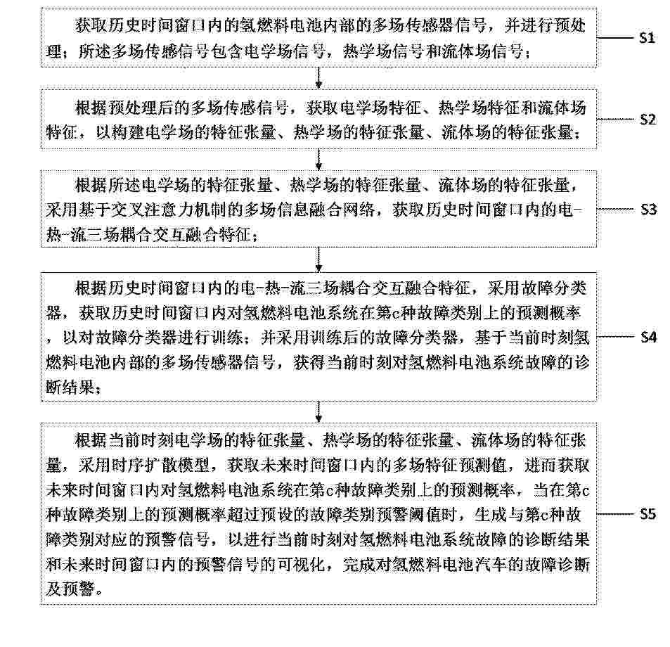
Output data including an FC current i(t), a first cell voltage V1(t), a first feature amount X1(t), and a second feature amount X2(t) of a fuel cell at a time t is obtained sequentially. Next, from among output data, time t and first cell voltage V1(t) when FC current i(t) is a representative current ir are extracted, and a representative I-V characteristic Vf(t, ir) is calculated using these. Next, from among output data, time t, first feature amount X1(t), and the second feature amount X2(t) when the FC current i(t) is the representative current ir are extracted, and a temporary fluctuation Ym(X1, X2) in cell voltage is calculated using these. Next, an average I-V characteristic Vmean(t, ir) at the time t is calculated by subtracting Ym(X1, X2) from Vf(t, ir). Further, it is determined on the basis of Vmean(t, ir) whether or not the fuel cell has malfunctioned or deteriorated.

GAS TURBINE ENGINE AND FUEL CELL ASSEMBLY

Nº publicación: US20260201837A1 16/07/2026

Solicitante:

GENERAL ELECTRIC CO [US]
General Electric Company

US_20260201837_A1

Resumen de: US20260201837A1

A gas turbine engine is provided. The gas turbine engine includes a turbomachine having a turbomachine having a compressor section, a combustor, and a turbine section arranged in serial flow order, the turbomachine further including an outer casing; and a fuel cell assembly positioned within the outer casing of the turbomachine, the fuel cell assembly including a fuel cell, an inlet line in fluid communication with an inlet of the fuel cell, and an output products line in fluid communication with an outlet of the fuel cell for receiving output products from the fuel cell, wherein the inlet line is positioned to be in thermal communication with the output products during operation of the gas turbine engine.

traducir