Si deseas distinguir tus productos, servicios o ambos de los de otra empresa, es posible que necesites una marca o nombre comercial. Descubre qué son, en qué consiste su procedimiento de registro y qué implica.

Información sobre los plazos de presentación de solicitudes de transformación de marcas de la Unión Europea en marca nacional española. Más información


Si tienes un nuevo dispositivo, producto o procedimiento que resuelva un problema técnico o tenga una ventaja práctica, existen distintas formas de protegerlo en España y en otros países. Descubre cómo hacerlo.

¿Tu innovación reside en la estética, la ornamentación o la apariencia de tu producto? Protégela mediante un diseño industrial. Descubre qué derechos confiere el registro y cómo realizar la tramitación.

Las indicaciones geográficas protegen el nombre de un producto originario de una zona geográfica, a la cual le debe una determinada calidad, reputación u otra característica. Descubre qué son, en qué consiste su procedimiento de registro y qué beneficios conceden.

Las patentes publicadas en todo el mundo son una valiosa fuente de información científica, técnica y comercial.

Si eres emprendedor/a o una empresa y quieres potenciar y mejorar la rentabilidad de tu negocio protegiendo de forma adecuada los activos intangibles de tu organización, en este espacio encontrarás lo necesario.


 156
resultados
156
resultados
 Última actualización
02/07/2026 [06:48:00]
Última actualización
02/07/2026 [06:48:00]


 Resultados 75 a 100 de 156

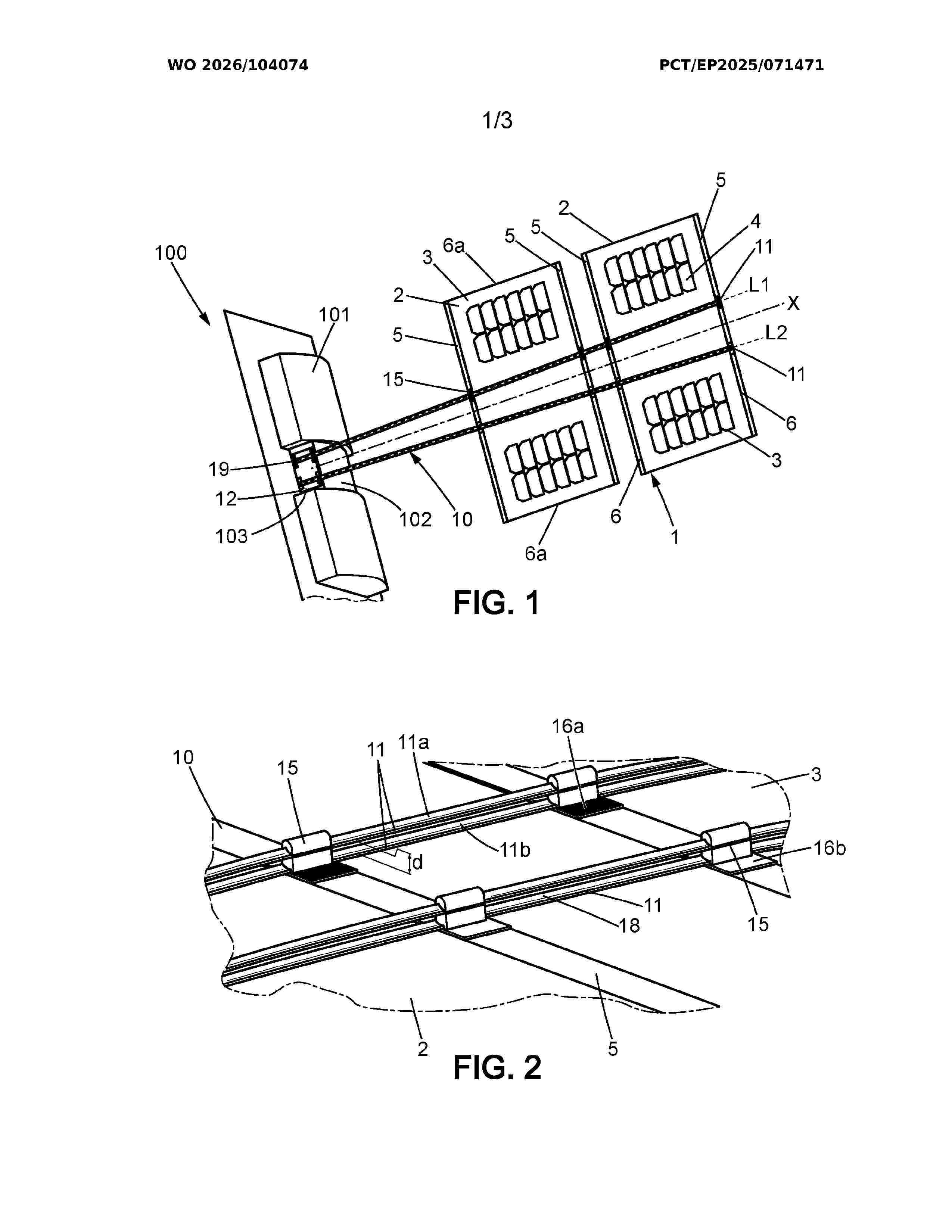
Resumen de: WO2026104074A1
A solar wing (1) for a spacecraft (100), the solar wing (1) being configured to be movable between a stowed position and a deployed position wherein the solar wing (1) comprises: a. at least one solar panel (2) positioned along a longitudinal axis (X), in the deployed position, each solar panel (2) comprising a flexible sheet (3) supporting solar cells (4), b. on each solar panel (2), at least two electrically conductive transversal bands (5) fixed to two opposite edges (6) that are transversal to the longitudinal axis (X) and that are electrically and mechanically connected to the solar cells (4), c. a back-bone structure (10) comprising at least one pair of electrically conductive C-shaped tape springs (11) fixed to said solar panel (2) and configured to link said solar panel (2) to the spacecraft (100), the back-bone structure (10) extending in at least one line in the deployed position from a connecting area (12) to the solar panel (2) that is distal from the spacecraft (100) in the deployed position, the connecting area (12) being configured to mechanically and electrically connect the solar wing to the spacecraft (100), wherein the transversal bands (5) and the back-bone structure (10) are connected to each other and are configured to transport electrical energy from the solar cells (4) to the connecting area (12).

Resumen de: EP4770346A2
The present application applies to the field of solar cell technology and provides a back-contact solar cell, back-contact solar cell assembly, and photovoltaic system. The groove area and non groove area are alternately disposed on the shady face of silicon chip. At a predetermined position in the groove area, a first doped layer has an extending portion that extends above the groove area, and the second doped layer has a wrapping portion which covers and recombines with the first surface of the extending portion. No silicon wafer part is provided on the side of the position where the wrapping portion recombines with the first surface, and the edge recombination generated by the boundary area between them has a relatively narrow impact range, which can effectively improve the efficiency with a higher filling factor. Meanwhile, the recombination between the wrapping portion and the first surface of the extending portion can provide a certain recombination area to increase the current during electrical injection, and improve the repair efficiency and effectiveness during the subsequent repair of back-contact solar cells.
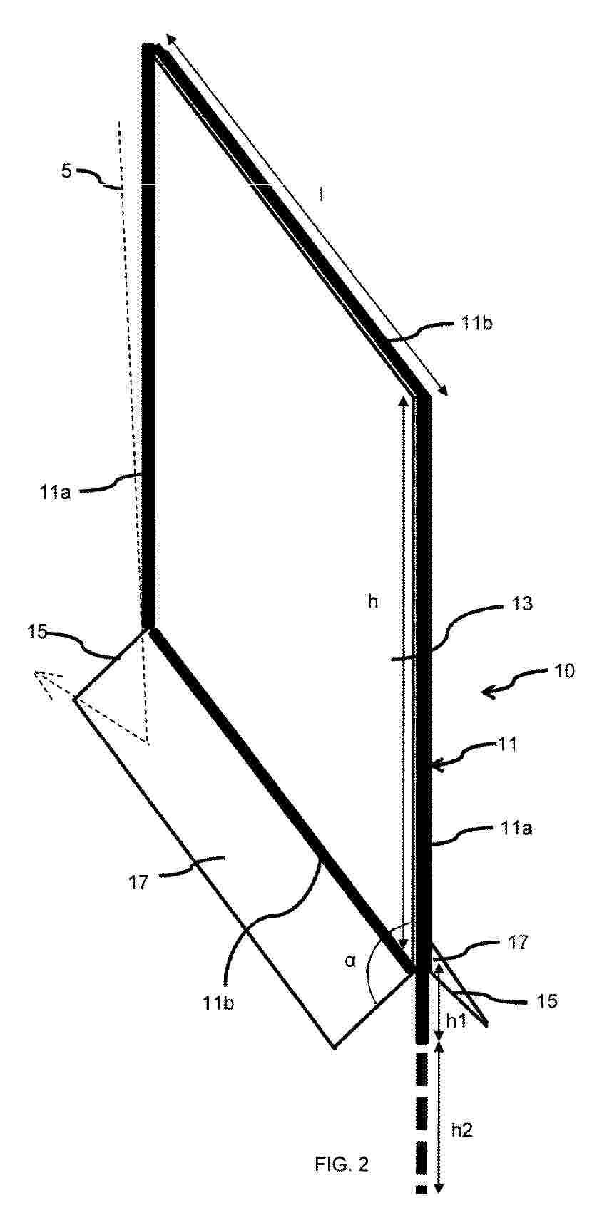
Resumen de: EP4769938A1
The present invention refers to a photovoltaic equipment (10) comprising:- a carrying structure (11),- at least one photovoltaic module (13) arranged sensibly vertically on the carrying structure (11),- at least one reflective surface (17) with a top side arranged on the carrying structure (11) below the, at least one, photovoltaic module (13),wherein the angle between the reflective surface (17) and the photovoltaic module (13) is higher than 90°.
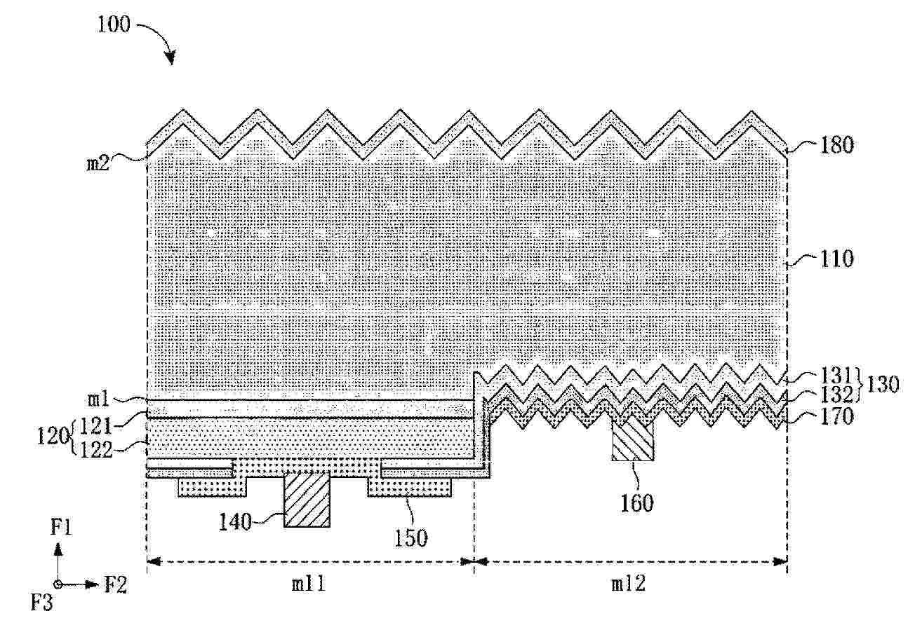
Resumen de: EP4770339A2
0001 A back contact cell (100) includes a substrate (110), a plurality of first passivation contact layers (120), and a plurality of second passivation contact layers (130). The substrate has a first surface (m1), and the first surface defines a plurality of first zones (m11) and a plurality of second zones (m12) that are alternately arranged. The first passivation contact layer (120) includes a tunneling layer (121) and a first doped layer (122). The second passivation contact layer (130) includes an amorphous material layer (131) and a second doped layer (132). The first surface defines a middle region (mz) and two edge regions (mb). On at least one edge region (mb), along the arrangement direction of the first zones (m11) and the second zones (m12), a total size of the first passivation contact layers (120) is greater than a total size of the second passivation contact layers (130) located on the second zones (m12).
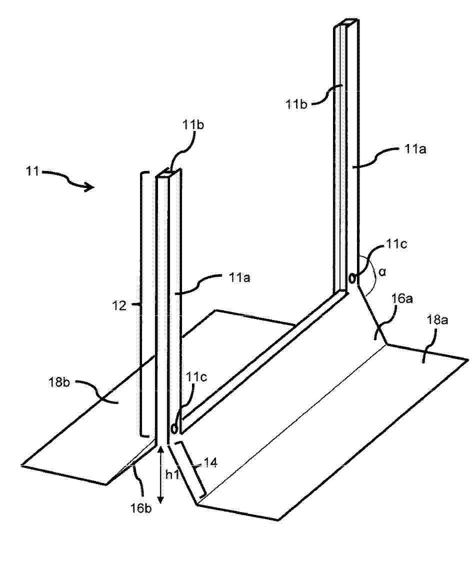
Resumen de: EP4769937A1
The present invention refers to a photovoltaic module carrying structure (11) comprising a metallic frame providing:- a holding part (12) comprising a first vertical post (11a) comprising a first slot (11b) configured for receiving a first side edge of a photovoltaic module (13) and a second vertical post (11a) comprising a second slot (11b) configured for facing the first slot (11b) for receiving a second side edge of the photovoltaic module (13),- a supporting part (14) comprising a first surface (16a) configured for extending from the bottom of the holding part (14) on a first side of the holding part (12) with an angle higher than 90°, with respect to the orientation of the first vertical post (11a) and the second vertical post (11a) and a second surface (16b) configured for extending from the bottom of the holding part (12) on a second side of the holding part (12) opposite to the first side with an angle higher than 90° with respect to the orientation of the first vertical post (11a) and the second vertical post (11a).
Resumen de: EP4770347A1
The present disclosure provides a solar cell and a preparation method therefor. The solar cell comprises a silicon substrate; the silicon substrate comprises a first surface and a second surface which are oppositely arranged; a diffusion layer is formed on the first surface of the silicon substrate; the first surface comprises first areas and second areas distributed at intervals; the second surface comprises third areas and fourth areas distributed at intervals; each first area is provided with a first tunnel passivation structure and a first electrode; and each third area is provided with a second tunnel passivation structure and a second electrode.
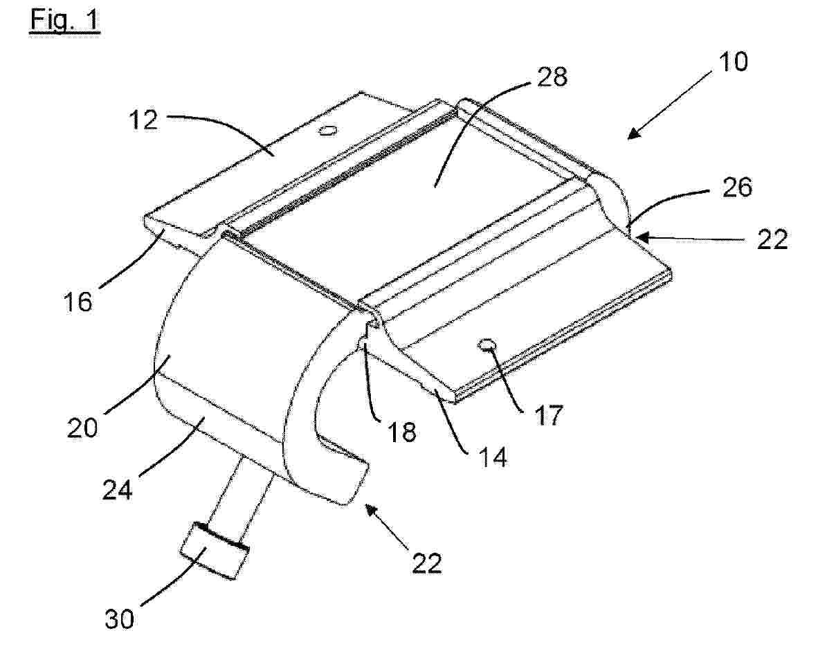
Resumen de: WO2025149362A1
The invention relates to a fastening device (10) for fastening at least one frame (38), preferably a module frame of a solar or photovoltaic module, to a framework (36), preferably a mounting rail, having a holding body (12) with a frame placement region (14) and a framework placement region (16), a fastening body (20) with a fastening portion (22) extending underneath the frame placement region (14) and/or the framework placement region (16), and a fixing element (30), preferably a screw, which is arranged in or on the fastening portion (22) of the fastening body (20).
Resumen de: WO2025144533A1
An ultra-thin transmissive cadmium (Cd) alloy solar cell is provided. The ultra-thin transmissive cadmium (Cd) alloy solar cell includes a substrate section, a conductive section, a window section, and an absorber section. The absorber section includes a transmissive cadmium (Cd) alloy and a seven hundred (700) or less nanometer (nm) section thickness. The ultra-thin transmissive cadmium (Cd) alloy solar cell includes a percent (10%) transmissivity for portions of a first irradiance wavelength range between three hundred fifty (350) nanometers (nm) to approximately eight hundred twenty-five (825) nanometers (nm). The ultra-thin transmissive cadmium (Cd) alloy solar cell includes a sixty-five percent (65%) transmissivity for portions of a second irradiance wavelength range between to approximately eight hundred twenty-five (825) nanometers (nm) to one thousand two hundred (1200) nanometers (nm).
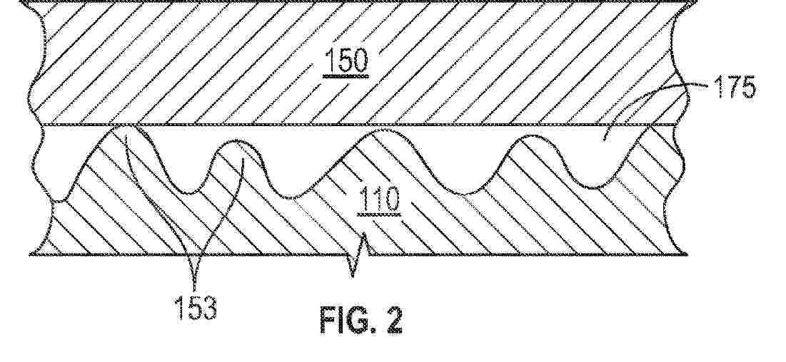
Resumen de: WO2025040970A1
A system is described comprising a solar article (110) that comprises a first major surface (that faces the sun during daytime use) and an opposing second major surface. The protective film (150) comprises a first major surface (that faces the sun during daytime use) and an opposing second major surface. The first major surface of the solar article (110) and/or the opposing second major surface of the protective film (150) comprises surface structures (153). The surface structures (153) are microstructures and/or nanostructures having at least two dimensions less than 1 mm. The structures can provide/maintain an air interface (175) between the first major surface of the solar article (110) and the second major surface of the protective film (150). Also described is a structured polyolefin film suitable for use as a protective film (150) for a solar article, as described herein and a method of improving the efficiency of a solar article.
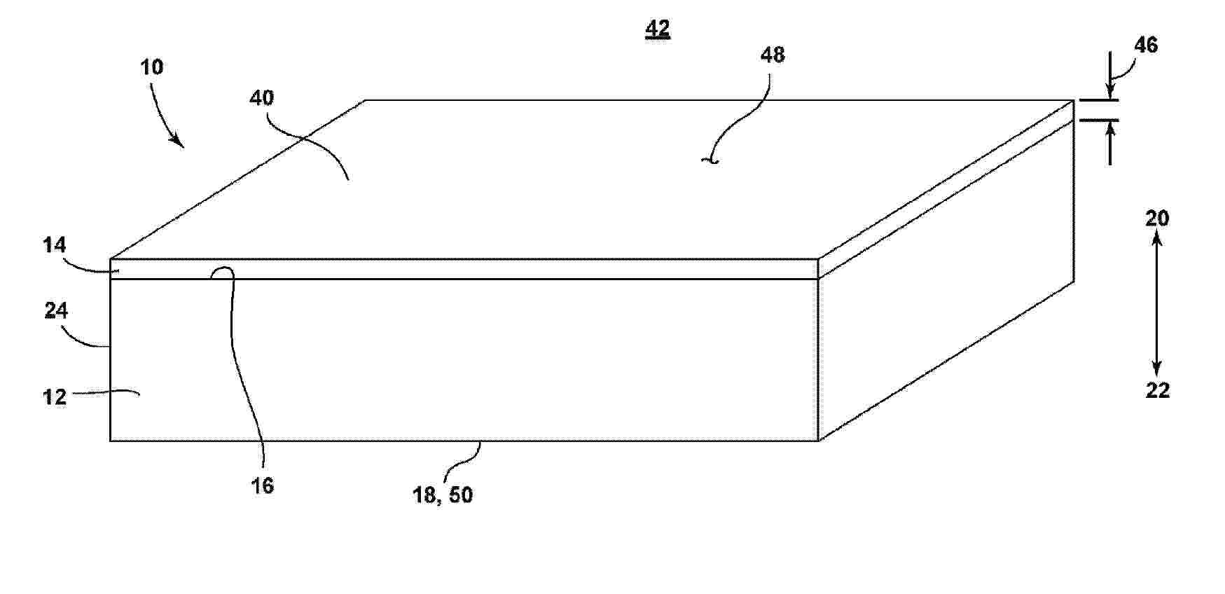
Resumen de: WO2025042702A1
An article is described herein that comprises: a substrate comprising a first major surface and a second major surface; and a multilayer coating disposed on the first major surface of the substrate, the multilayer coating comprising at least one period of a layer of low refractive index material and a layer of high refractive index material. The article exhibits a prime surface average reflectance of less than or equal to 0.550% across an entire wavelength range of from 600 nm to 750 nm. A solar panel including the article as a cover glass disposed over an array of photovoltaic cells.
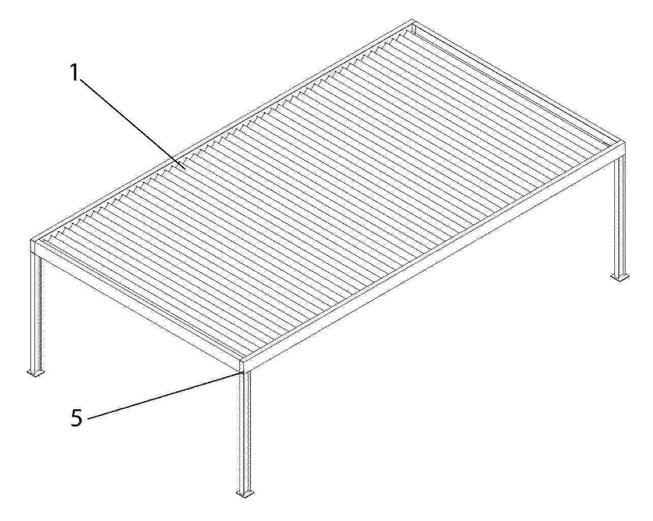
Resumen de: EP4768675A1
The invention relates to a retractable, adjustable photovoltaic bioclimatic pergola comprising a set of slats (1) incorporating photovoltaic cells (2) designed to capture solar radiation and convert it into electrical energy. The slats are connected to a transmission system (3) enabling controlled movement.
Resumen de: US2025070712A1
0000 An automated maintenance system for solar components is disclosed. The system includes a condensate reservoir, a wiping element, a motor, and a fluid delivery element. The fluid delivery element is configured to transport a fluid from the condensate reservoir to a solar component, and the motor is configured to operate the wiping element via a controller. The system is designed to clean solar components automatically, without the need for manual intervention. The system is efficient, cost-effective, and environmentally friendly.
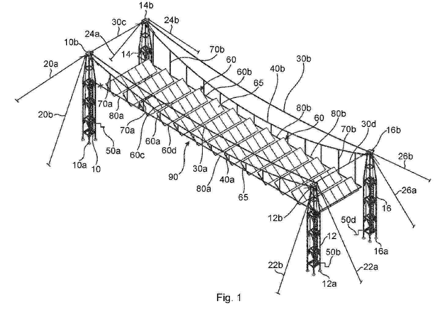
Resumen de: WO2025040745A1
A solar panel suspension system comprising; at least four uprights (10, 12, 14, 16), each upright exhibiting a bottom end (10a, 12a, 14a, 16a) and a top end (10b, 12b, 14b, 16b), said at least four uprights being arrangeable in pairs, wherein each pair comprises two uprights aligned in a first direction and wherein the pairs are arranged in parallel, side by side in a second direction which is perpendicular to the first direction. Supporting wires (20a 20b, 22a, 22b, 24a, 24b, 26a, 26b, 30a 30b, 30c, 30d) are arranged to support the uprights by supportingly connecting each upright to the ground and to at least two neighbouring uprights. At least two first suspension wires (40a, 40b) are arranged to extend in a first direction between the top end of two uprights in a respective pair of uprights. The system further comprises a plurality of rectangular planar support frames (60), which are arranged to be supportingly connected to two first suspension wires (40a, 40b). A hoisting arrangement (50a, 50b, 50d) is arranged to extend and retract each first suspension wire (40a, 40b) from the top end of both uprights (10, 12, 14, 16) in each pair of uprights. A method of erection such a system is also described.
Resumen de: EP4770345A1
0001 Provided are a solar cell, a method for preparing the same, and a photovoltaic module. The solar cell includes a silicon substrate, a tunneling passivation contact structure, and a second electrode. The silicon substrate includes a first surface and a second surface arranged opposite to the first surface. The second surface includes first regions and second regions that are alternately arranged. A tunneling passivation is disposed on the second surface. A projection of the tunneling passivation contact structure on the second surface of the silicon substrate is located within the first region. The tunneling passivation contact structure includes a tunneling layer in direct contact with the silicon substrate, a second doped layer disposed on the tunneling layer, and a blocking layer and a third doped layer that are sequentially disposed on the second doped layer. The second doped layer, the third doped layer and the silicon substrate contain impurities of same conductive type. The second electrode is disposed in the second region and in contact with the third doped layer. The solar cell of the present disclosure can reduce parasitic absorption on the back surface of the cell and increase a current, without affecting contact performance between the electrode and the doped layer on the back surface, thereby improving a cell efficiency and bifaciality and enhancing a process window.
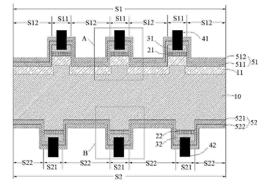
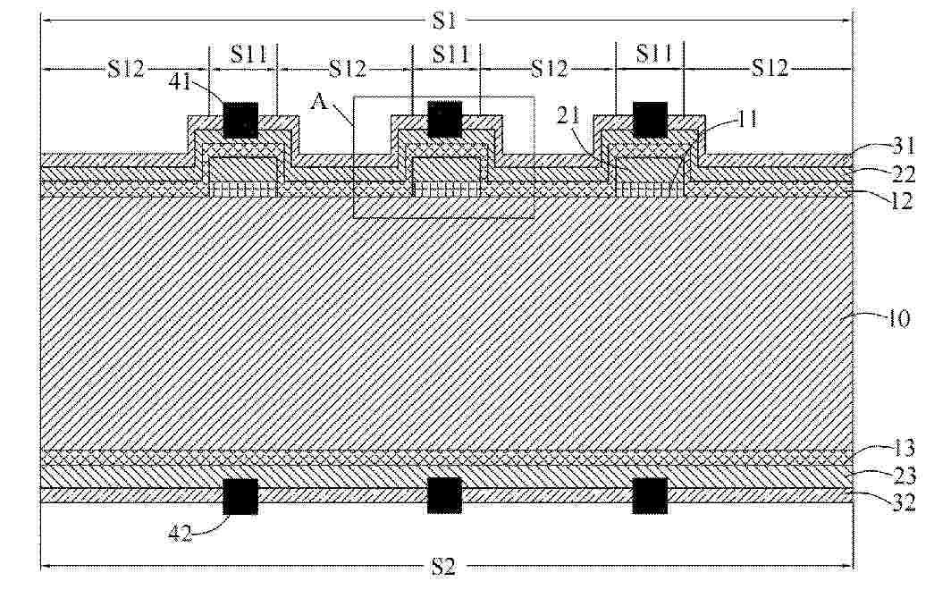
Resumen de: EP4770337A1
0001 Provided are a solar cell and a manufacturing method therefor. The solar cell includes a silicon substrate (10) including a first surface (S1) and a second surface (S2) opposite to each other, where the first surface (S1) includes a first region (S11) and a second region (S12) arranged at intervals, a tunneling passivation structure is provided on the first region (S11), a passivation structure is provided on the second region (S12), a first electrode (41) electrically connected to the tunneling passivation structure is further provided on the first region (S11), and the width W of the first region (S11) is greater than the width L of the first electrode (41).
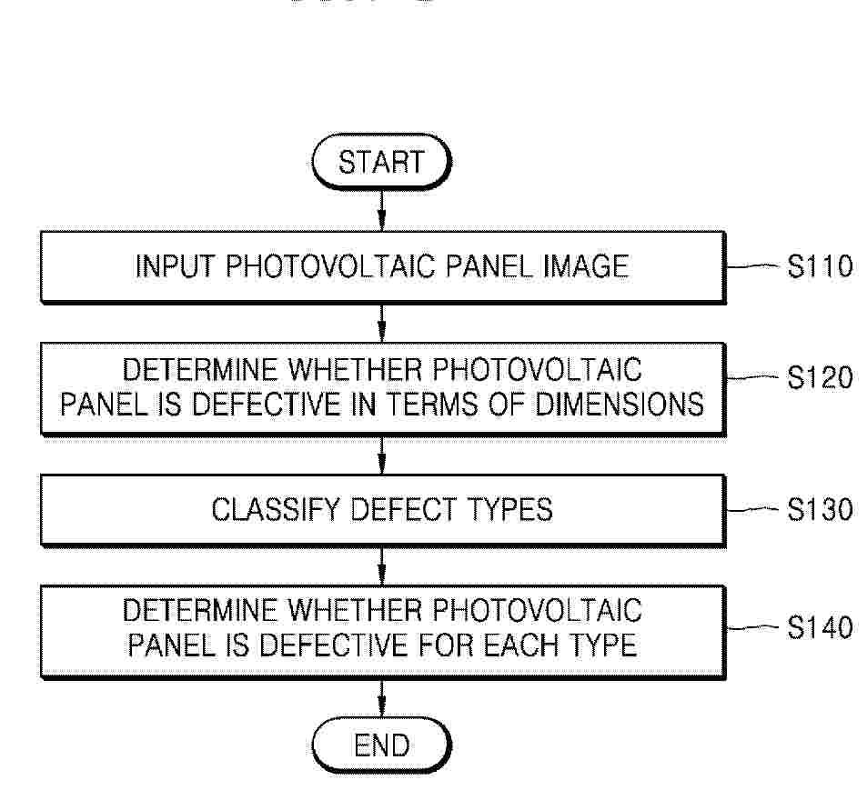
Resumen de: EP4769941A1
0001 The present disclosure relates to a method and device for detecting defects in a photovoltaic panel by using an image of the photovoltaic panel, and according to the method and device for detecting defects in a photovoltaic panel, it is possible to determine whether a photovoltaic panel is defective more quickly and accurately during a photovoltaic panel production process, by using a pre-trained artificial intelligence unit to detect defects, which are undetectable in an electroluminescence (EL) image, in an optical image of a photovoltaic panel rather than an EL image, and classify the detected defects by type, and measuring sizes of the defects to finally determine whether the photovoltaic panel is defective, thereby providing advantageous effects of shortening process time and reducing cost losses by improving a defect detection rate.
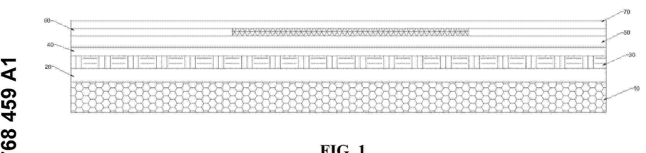
Resumen de: EP4768459A1
Disclosed in the present invention is a building-integrated photovoltaics system, comprising a back plate layer, a photovoltaic cell layer, and a facing layer from inside to outside. The facing layer comprises, in percentage by weight, 30-40% of a hydraulic material, 30-50% of natural calcium carbonate, 7-16% of an acrylic emulsion, 5-12% of glass fiber powder, 0.1-0.5% of a silane coupling agent, 0.1-0.5% of an acrylic light diffusing agent, and 5-20% of water. In the present invention, the building-integrated photovoltaics system is mounted on a building external wall, a building roof and a roof extension, can implement solar power generation, and is integrated with a building; external colors and patterns match the building; and the function of solar power generation is achieved while the aesthetics of the building is not damaged.
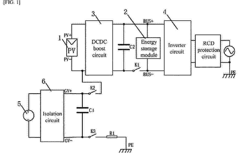
Resumen de: EP4769939A1
0001 Provided are a potential induced degradation (PID) repair circuit and PID repair method for a photovoltaic (PV) system. The PV system includes a solar cell module, an energy storage module, a direct current direct current (DCDC) boost circuit, and an inverter circuit; the PID repair circuit includes a DC power supply and an isolation circuit; after the DC power supply is processed by the isolation circuit, one end of the isolation circuit is connected to a positive terminal PV+ or a negative terminal PV- of the solar cell module, and another end of the isolation circuit is connected to a ground terminal PE; and a first switch is disposed on a connection path between the solar cell module and the energy storage module; PID repair is performed on the solar cell module by applying a negative voltage to the positive terminal PV+ of the solar cell module or a positive voltage to the negative terminal PV- of the solar cell module via the DC power supply; and a connection path between the solar cell module and the inverter circuit is disconnected during the PID repair. This application can prevent an internal short circuit caused by the inverter circuit during the PID repair, thereby effectively guaranteeing the operational safety of the PV system.
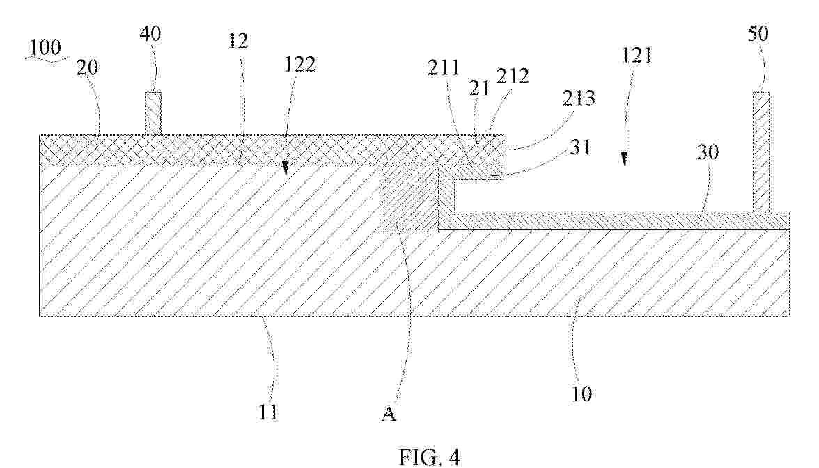
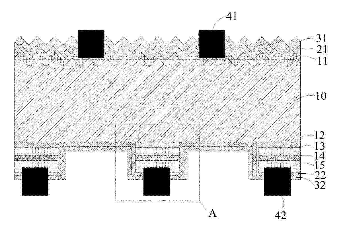
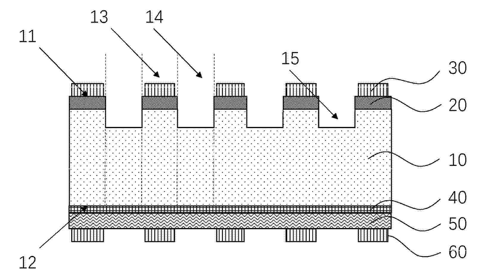
Resumen de: EP4770338A2
0001 A photovoltaic cell includes a silicon substrate (10), a doped region (20) and a first electrode (30). The silicon substrate (10) has a first surface (11) and a second surface (12) opposite to each other. The first surface (11) defines a first region (13) and a second region (14), the doped region (20) is located in the first surface (11) in the first region (13). The first electrode (30) is electrically connected to the doped region (20); and the silicon substrate (10) is provided with a groove (15) in the second region (14). In a thickness direction of the silicon substrate (10), a depth of the groove (15) is in a range of 1.5µm to 3µm.
Resumen de: CO2026005382A1
La invención se refiere a un dispositivo de seguimiento para módulos solares y/o fotovoltaicos, que comprende al menos dos postes, un tubo central que se extiende al menos parcialmente entre los postes y está montado de forma giratoria en ellos, un segmento de arco conectado al tubo central de manera fija en rotación y que presenta varios rebajes dispuestos lateralmente, y una transmisión por engranajes con dientes, en la que la transmisión por engranajes está configurada para acoplarse a los rebajes mediante sus dientes.
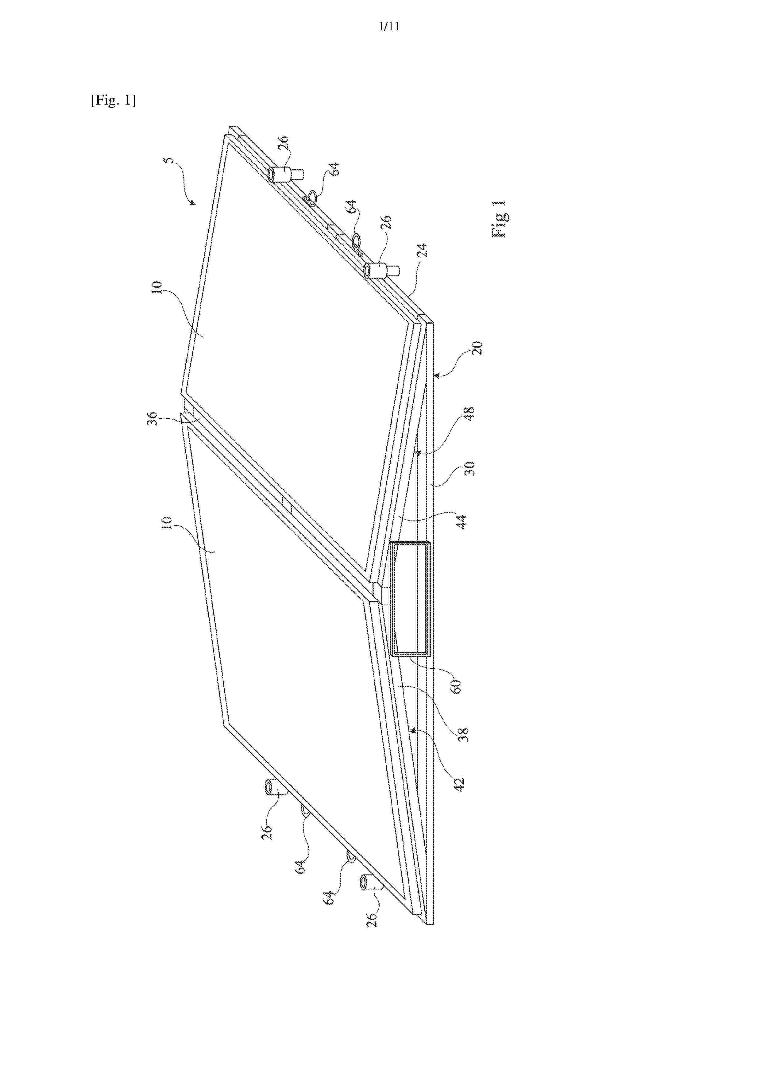
Resumen de: FR3170746A1
Structure photovoltaïque La présente description concerne une structure photovoltaïque (5) comprenant un panneau photovoltaïque (10) et un support (20) configuré pour supporter le panneau photovoltaïque (10), la structure photovoltaïque étant gerbable. Figure pour l'abrégé : Fig. 1
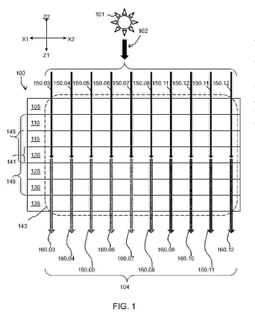
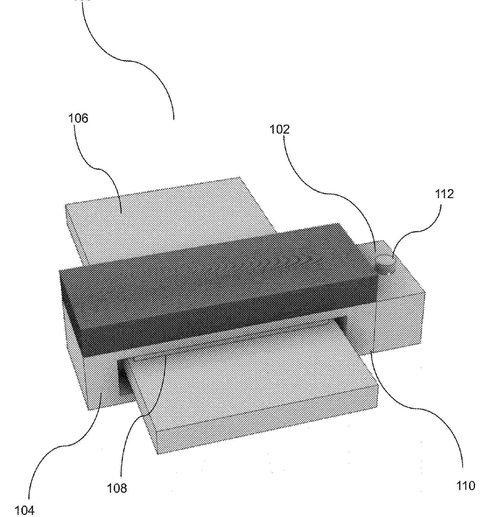
Resumen de: FR3170600A1
Procédé et système de détermination d’une température nocturne au moyen d'un module photovoltaïque La présente description concerne un procédé de détermination d’une température ambiante extérieure nocturne Ta’ dans un système comportant un module photovoltaïque (104), le procédé comprenant: a) déterminer, au moyen d'un dispositif électronique de traitement (110), à partir de mesures du courant de court-circuit Isc et de mesures de la tension de circuit ouvert Voc du module photovoltaïque, une première valeur Ta1 représentative de la température ambiante extérieure au voisinage de l’aube d’une première journée et une deuxième valeur Ta2 représentative de la température ambiante extérieure au voisinage du crépuscule de la première journée ; etb) calculer, au moyen du dispositif électronique de traitement, à partir de la première valeur Ta1 et de la deuxième valeur Ta2, en utilisant une fonction mathématique Ta’ prédéfinie, un ensemble d’une ou plusieurs valeurs représentatif de l’évolution de la température ambiante extérieure nocturne au cours de la nuit suivant ladite première journée. Figure pour l'abrégé : Fig. 2
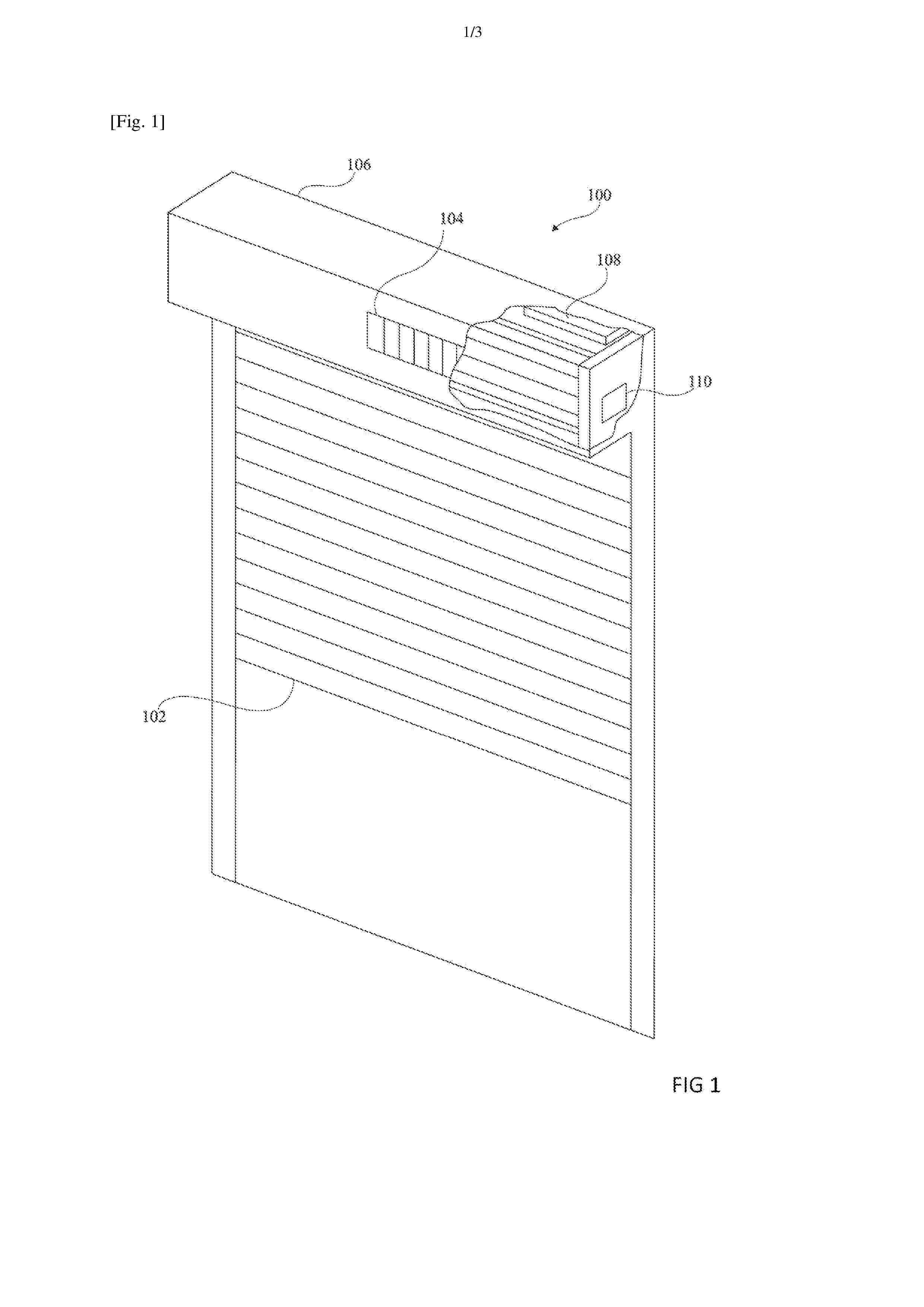
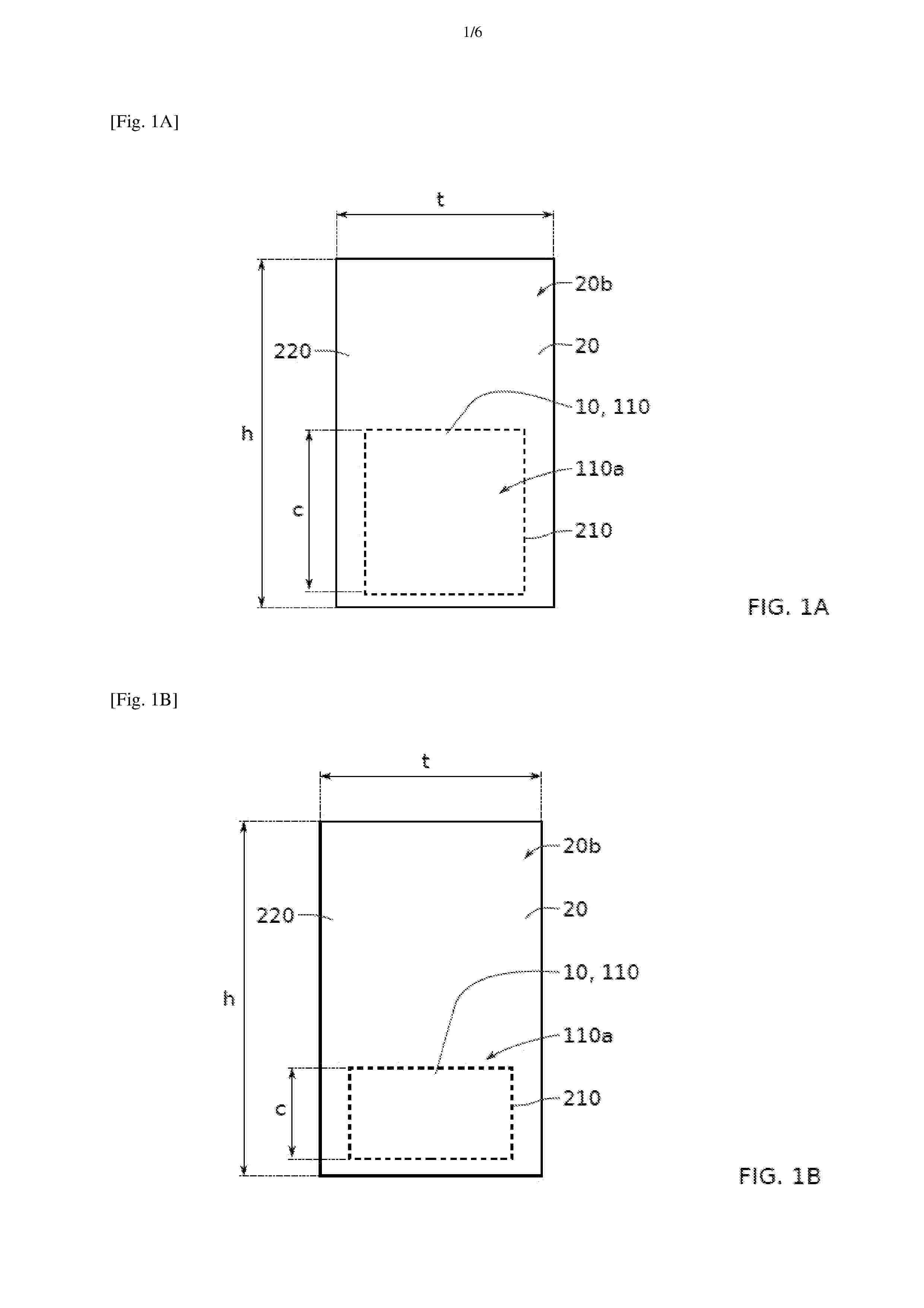
Resumen de: FR3170518A1
Titre : Tuile photovoltaïque et procédé de réalisation d’une tuile photovoltaïque L’invention concerne une tuile photovoltaïque (1) comprenant au moins un module photovoltaïque (10) comprenant au moins une cellule photovoltaïque (110) présentant une face avant (110a) destinée à recevoir un rayonnement solaire, un panneau (20) présentant une face interne (20a) tournée au regard de la face avant de la cellule photovoltaïque et une face externe (20b) tournée vers l’extérieur de la tuile photovoltaïque, le panneau (20) présentant, au moins dans une première zone (210) couvrant la face avant de la cellule photovoltaïque, une transparence au rayonnement solaire, caractérisé en ce que la tuile photovoltaïque comprend également une enveloppe élastique (30), l’enveloppe élastique (30) étant conformée de sorte à enserrer au moins une partie du module photovoltaïque, au moins une partie du panneau et au moins une partie d’une tuile passive (40). Figure pour l’abrégé : Fig.3A
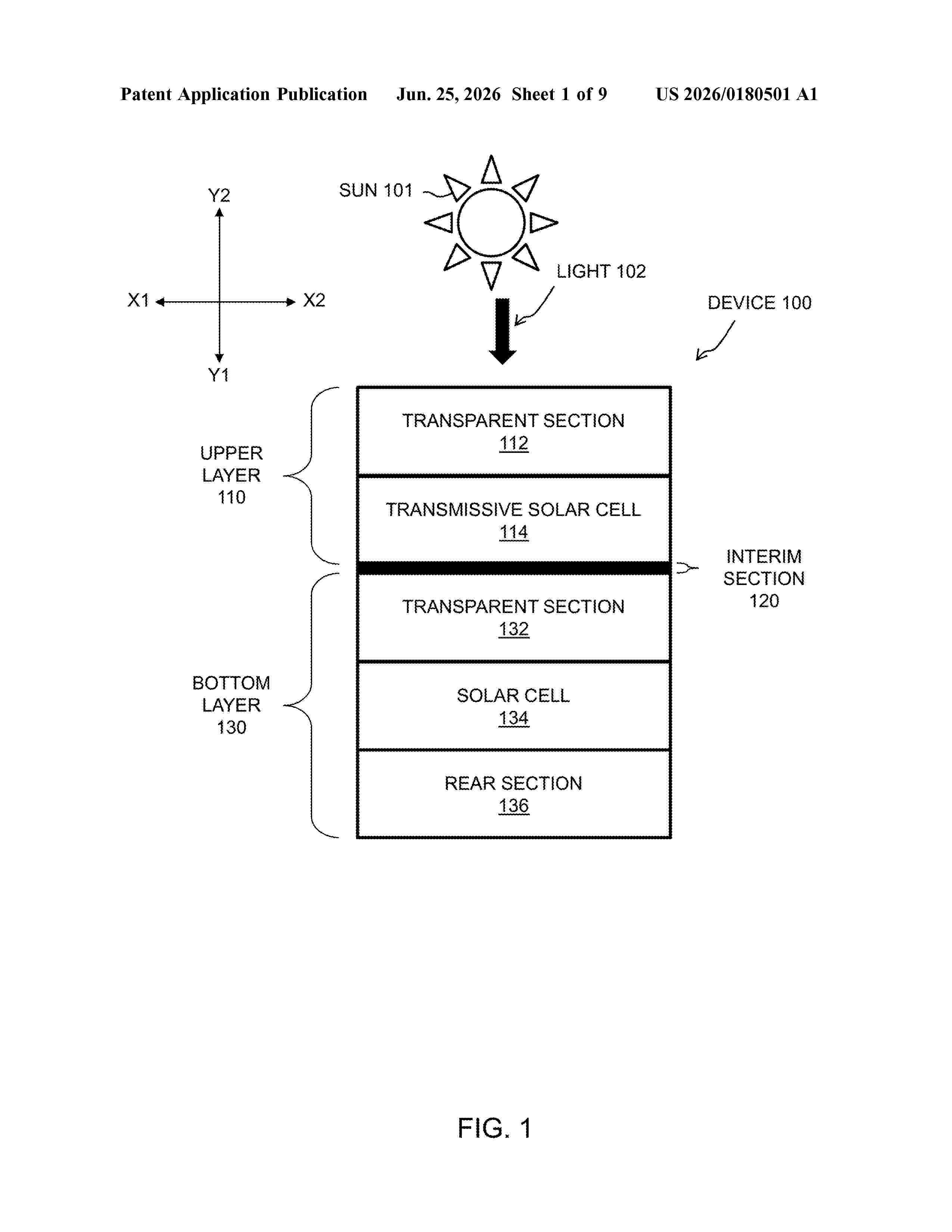
Resumen de: US20260180501A1
A device is provided. The device includes mechanically stacked layers. The mechanically stacked layers include a bottom layer and upper layers. Each upper layer includes a transmissive solar cell that converts light energy into electricity. Each upper layer transmits unconverted portions of the light energy towards the bottom layer. The bottom layer includes a solar cell that converts the unconverted portions of the light energy into electricity.
Nº publicación: US20260180495A1 25/06/2026
Solicitante:
UNIRAC INC [US]
Unirac, Inc.
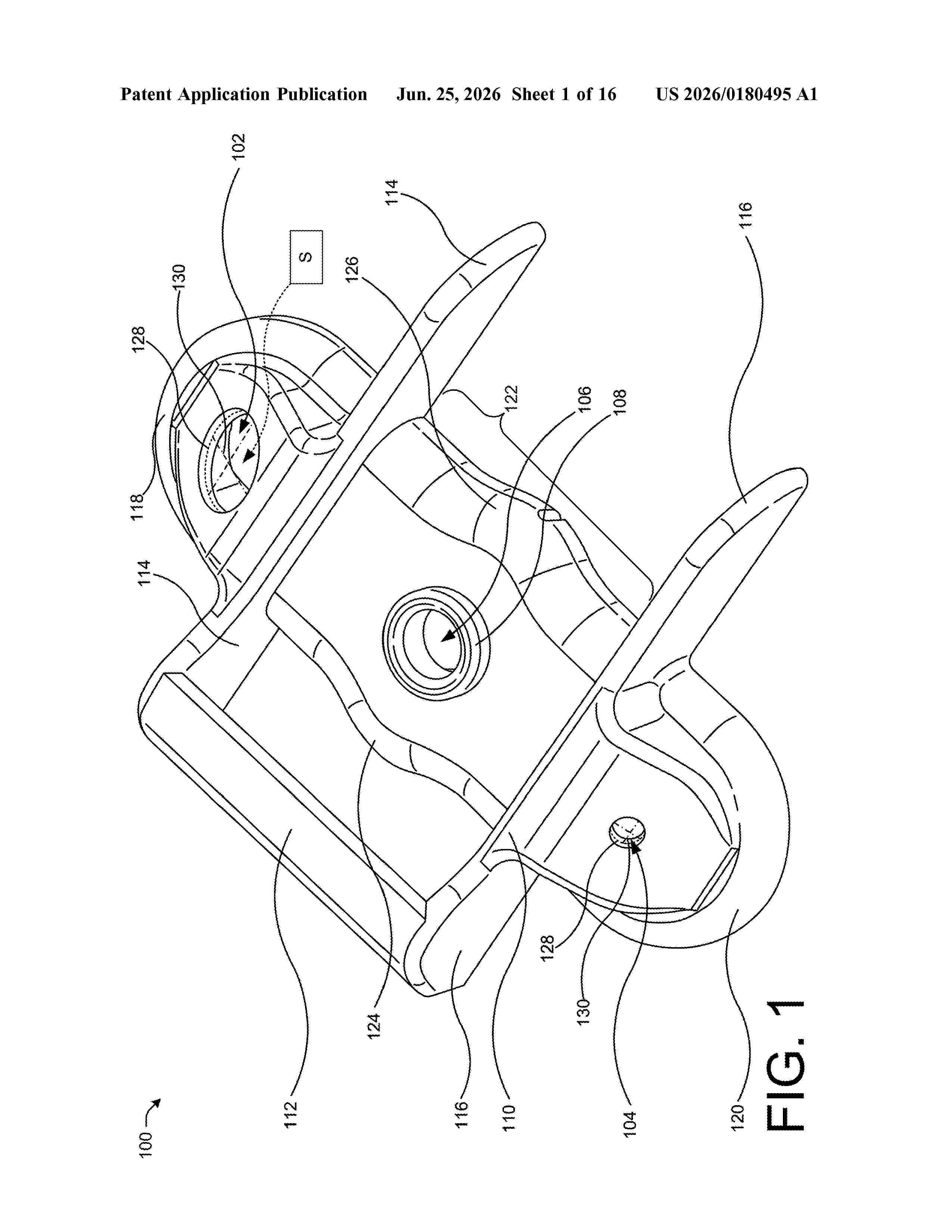
Resumen de: US20260180495A1
A mounting system includes a mounting device. The mounting device includes an internal cavity defined in a side of the mounting device, a first sealant aperture defined in the mounting device and opening into the internal cavity, a second sealant aperture defined in the mounting device and opening into the internal cavity, the first sealant aperture and the second sealant aperture being in fluid communication when the mounting device is placed on a surface for use, and a fastener aperture defined through the internal cavity. The mounting system further includes a coupling bracket including a bottom portion, an underside surface of which is correspondingly shaped in conformance with a shape of an outer surface of a central portion of the mounting device so as to be accommodated thereon when in use, and a fastener to couple the mounting device and the coupling bracket together via the fastener aperture.
 BOPI
BOPI
 Sede Electrónica