Si deseas distinguir tus productos, servicios o ambos de los de otra empresa, es posible que necesites una marca o nombre comercial. Descubre qué son, en qué consiste su procedimiento de registro y qué implica.

Información sobre los plazos de presentación de solicitudes de transformación de marcas de la Unión Europea en marca nacional española. Más información


Si tienes un nuevo dispositivo, producto o procedimiento que resuelva un problema técnico o tenga una ventaja práctica, existen distintas formas de protegerlo en España y en otros países. Descubre cómo hacerlo.

¿Tu innovación reside en la estética, la ornamentación o la apariencia de tu producto? Protégela mediante un diseño industrial. Descubre qué derechos confiere el registro y cómo realizar la tramitación.

Las indicaciones geográficas protegen el nombre de un producto originario de una zona geográfica, a la cual le debe una determinada calidad, reputación u otra característica. Descubre qué son, en qué consiste su procedimiento de registro y qué beneficios conceden.

Las patentes publicadas en todo el mundo son una valiosa fuente de información científica, técnica y comercial.

Si eres emprendedor/a o una empresa y quieres potenciar y mejorar la rentabilidad de tu negocio protegiendo de forma adecuada los activos intangibles de tu organización, en este espacio encontrarás lo necesario.


 1034
resultados
1034
resultados
 Última actualización
23/10/2026 [07:18:00]
Última actualización
23/10/2026 [07:18:00]


 Resultados 425 a 450 de 1034

Resumen de: WO2026214535A1
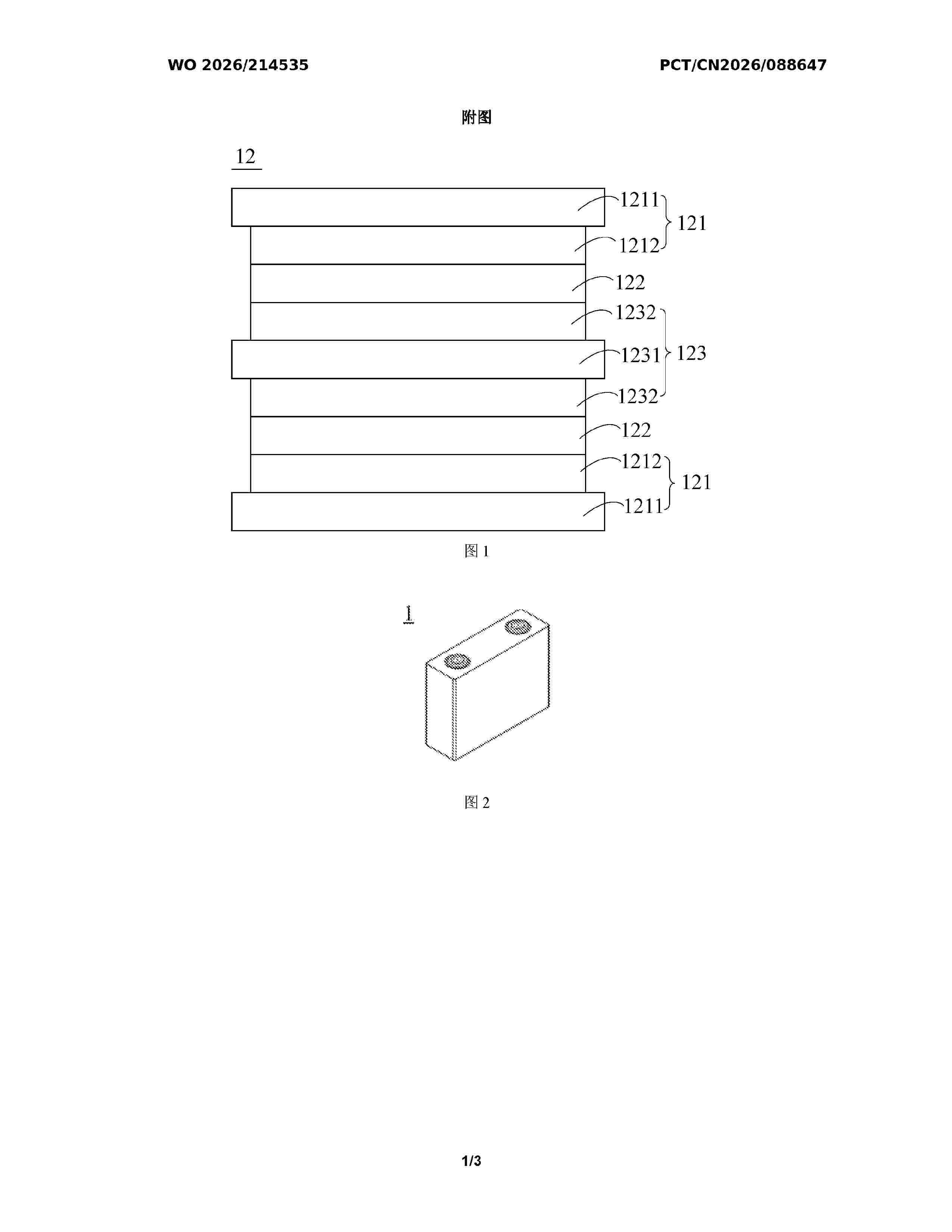
The present application provides a solid-state battery, a solid-state electrolyte membrane, a preparation method for the solid-state electrolyte membrane, and an electric device. The solid-state battery comprises a positive electrode layer, a solid-state electrolyte membrane, and a negative electrode layer, wherein the solid-state electrolyte membrane is located between the positive electrode layer and the negative electrode layer; the solid-state electrolyte membrane comprises a porous support and a solid-state electrolyte, the solid-state electrolyte is provided in pores of the porous support, and the tensile strength of the porous support is greater than the tensile strength of the solid-state electrolyte membrane.

Resumen de: DE102025114725A1
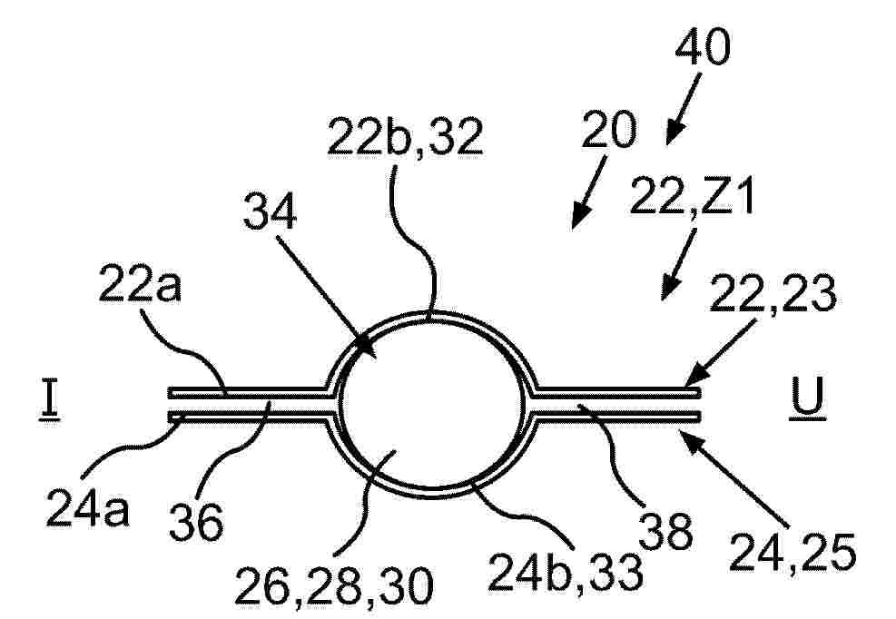
Die Erfindung betrifft eine Bauteilanordnung (20) mit einer fließfähigen Dichtmasse (26, 28), wobei die Bauteilanordnung (20) ein erstes Bauteil (22, 23) aufweist, das eine erste Fläche (22a) mit einem ersten Dichtbereich (22b) umfasst, und ein zweites Bauteil (24, 25) aufweist, das eine zweite Fläche (24a) mit einem zweiten Dichtbereich (24b) umfasst, wobei der erste Dichtbereich (22b) dem zweiten Dichtbereich (24b) gegenüberliegt, wobei die fließfähige Dichtmasse (26, 28) zwischen dem ersten und zweiten Dichtbereich (22b, 24b) und kontaktierend am ersten und zweiten Dichtbereich (22b, 24b) angeordnet ist. Dabei ist vorgesehen, dass zumindest der erste Dichtbereich (22b) als eine erste Nut (32) in der ersten Fläche (22a) ausgebildet ist, wobei die erste Nut (32) zusammen mit dem zweiten Dichtbereich (24b) eine Dichtkammer (34) bildet, in der die fließfähige Dichtmasse (26, 28) angeordnet ist.
Resumen de: WO2026213827A1
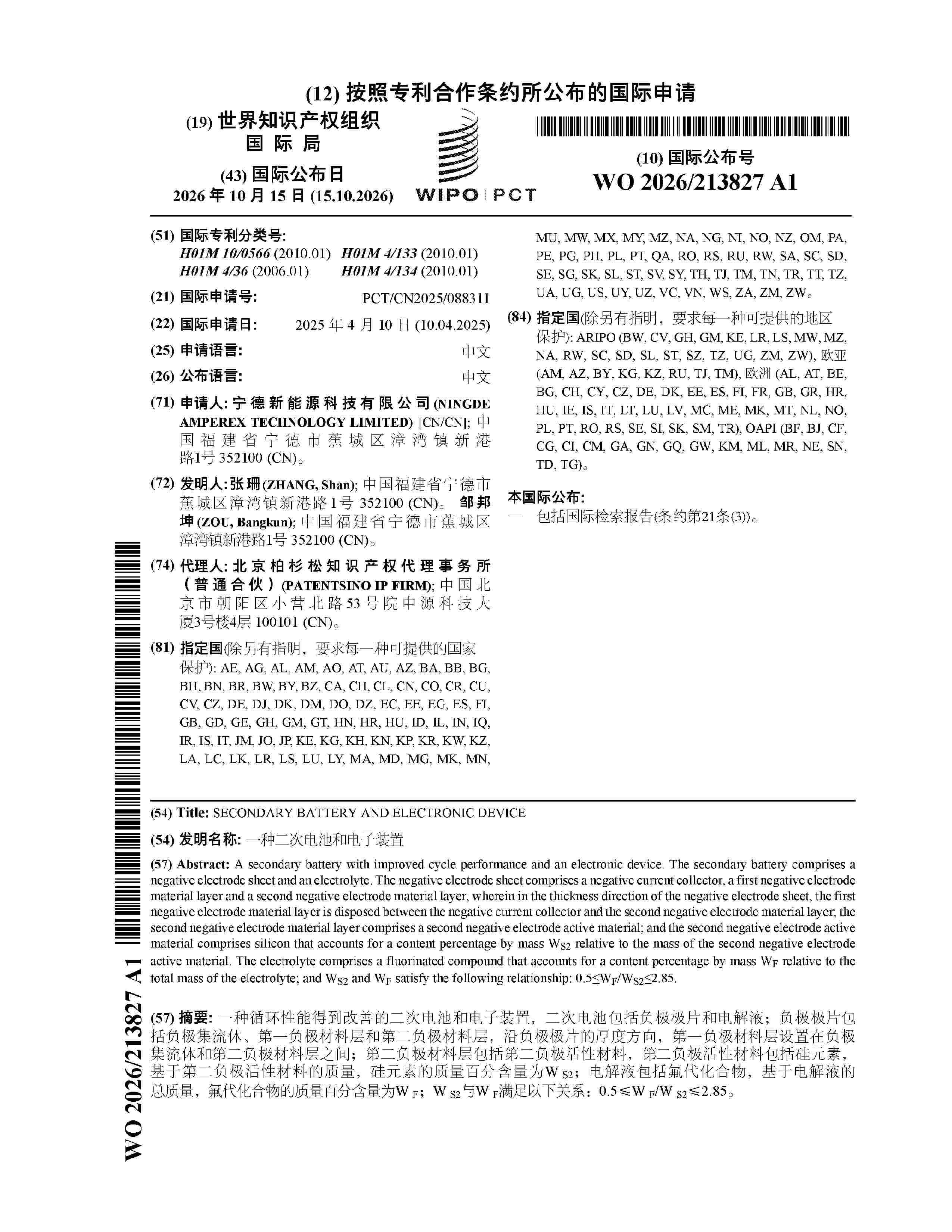
A secondary battery with improved cycle performance and an electronic device. The secondary battery comprises a negative electrode sheet and an electrolyte. The negative electrode sheet comprises a negative current collector, a first negative electrode material layer and a second negative electrode material layer, wherein in the thickness direction of the negative electrode sheet, the first negative electrode material layer is disposed between the negative current collector and the second negative electrode material layer; the second negative electrode material layer comprises a second negative electrode active material; and the second negative electrode active material comprises silicon that accounts for a content percentage by mass WS2 relative to the mass of the second negative electrode active material. The electrolyte comprises a fluorinated compound that accounts for a content percentage by mass WF relative to the total mass of the electrolyte; and WS2 and WF satisfy the following relationship: 0.5≤WF/WS2≤2.85.
Resumen de: WO2026216696A1
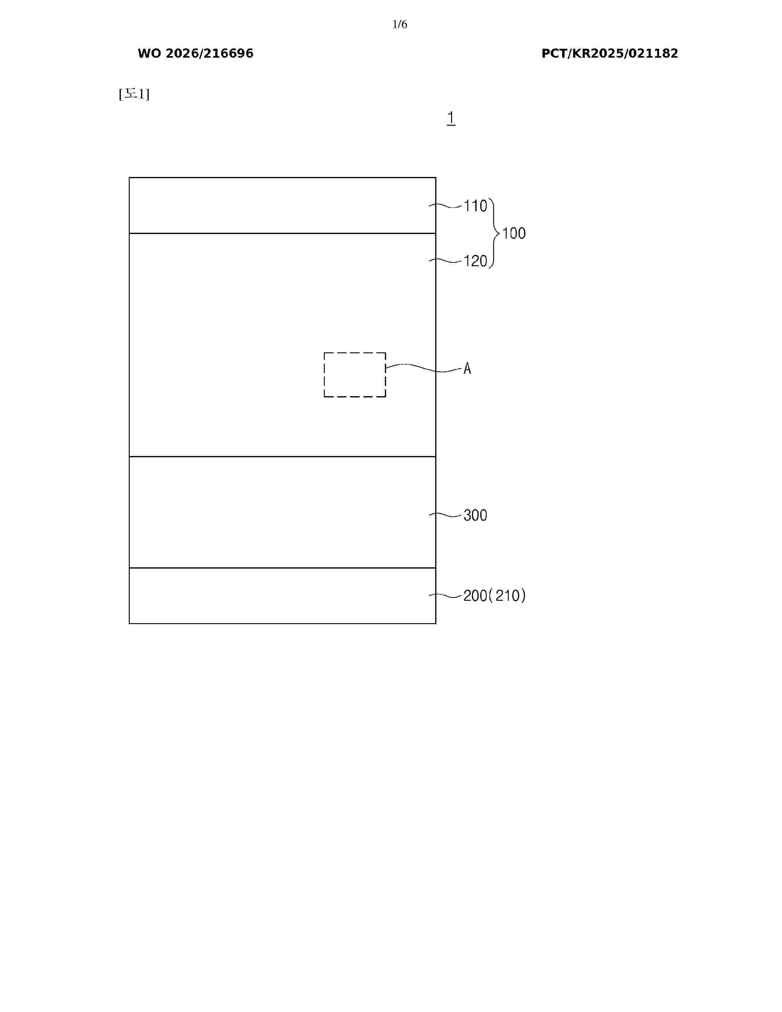
The present invention relates to a positive electrode for a lithium-sulfur battery and a lithium-sulfur battery comprising same. The positive electrode for a lithium-sulfur battery comprises: a positive electrode current collector; and a positive electrode active material layer disposed on at least one surface of the positive electrode current collector, wherein the positive electrode active material layer includes a positive electrode active material including a sulfide-based composite, a solid electrolyte, and a polymer composite, the sulfide-based composite includes a sulfur-based material, a metal halide salt, and a carbon-based material, and the polymer composite is derived from a mixture of a nitrile-based compound, an acrylate-based compound, and a lithium salt.
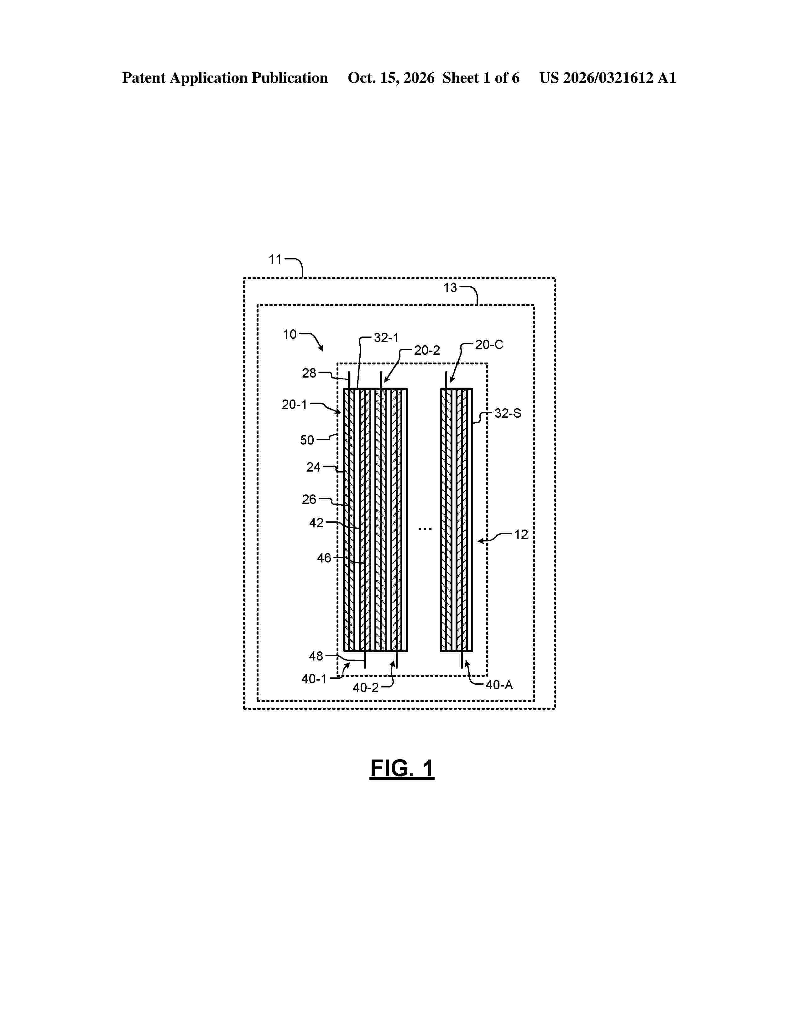
Resumen de: US20260321612A1
A solid-state battery cell includes C cathode electrodes including a cathode active material layer arranged on a cathode current collector, S separators, and A anode electrodes including an anode active material layer arranged on an anode current collector, where C, A, and S are integers. The anode active material layer includes ferrosilicon microparticles including a silicon framework and embedded ferrosilicon domains. The ferrosilicon microparticles may be produced by cleaning and crushing ferrosilicon rock to produce crushed ferrosilicon. The crushed ferrosilicon is milled to produce ferrosilicon microparticles. The ferrosilicon microparticles are separated from the crushed ferrosilicon using a sieve. The ferrosilicon microparticles include a silicon framework and embedded ferrosilicon domains. The ferrosilicon microparticles are mixed with a binder. The anode electrode includes the ferrosilicon microparticles and the binder.
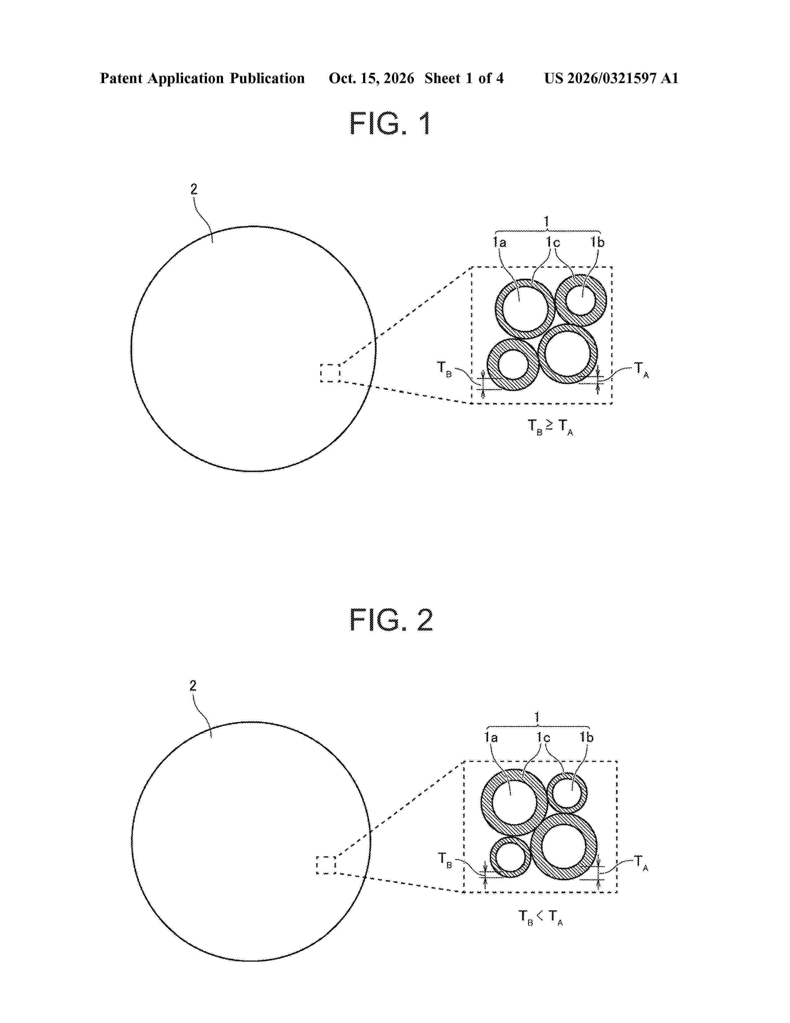
Resumen de: US20260321597A1
0000 A positive electrode active material includes a secondary particle, wherein: the secondary particle includes a first particle group, a second particle group, and a carbon layer; each of the first particle group and the second particle group is composed of primary particles; the first particle group has a larger average particle diameter than the second particle group; the primary particles contain an olivine-type compound; the carbon layer covers at least part of a surface of the primary particle and satisfies a relationship of T
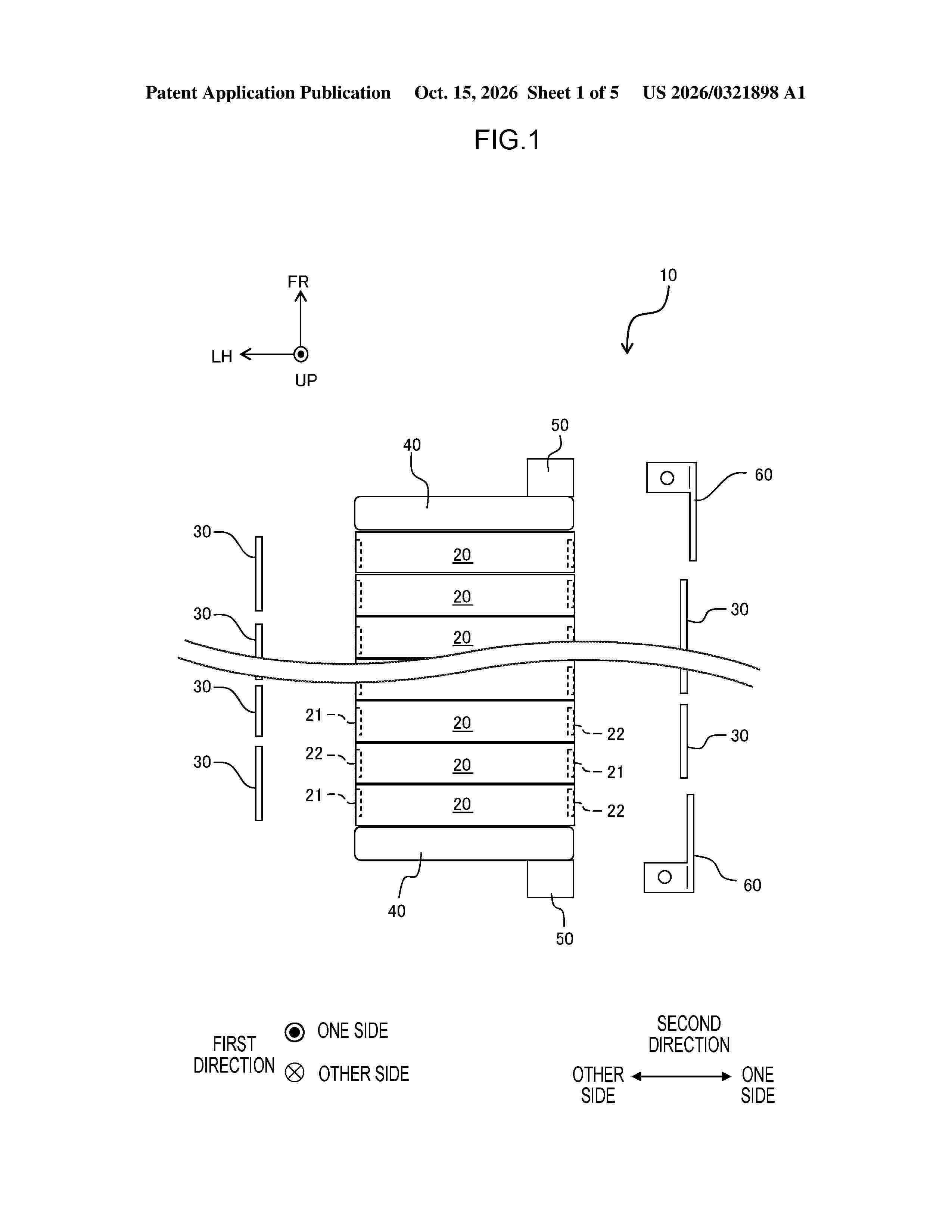
Resumen de: US20260321898A1
A battery module 10 includes plural battery cells 20 that include electrode terminals 21 and 22, a conductive member 60 that is connected to the electrode terminals 21 and 22 of at least one battery cell 20 of the plural battery cells 20, and a terminal block 50 to which the conductive member 60 is fixed. The conductive member 60 includes a first plate portion 61 having a plate thickness direction in a first direction. The first plate portion 61 is fixed to the terminal block 50. The conductive member 60 includes a second plate portion 62 having a plate thickness direction in a second direction that is a direction perpendicular to the first direction. The second plate portion 62 is fixed to the terminal block 50.
Resumen de: WO2026214222A1
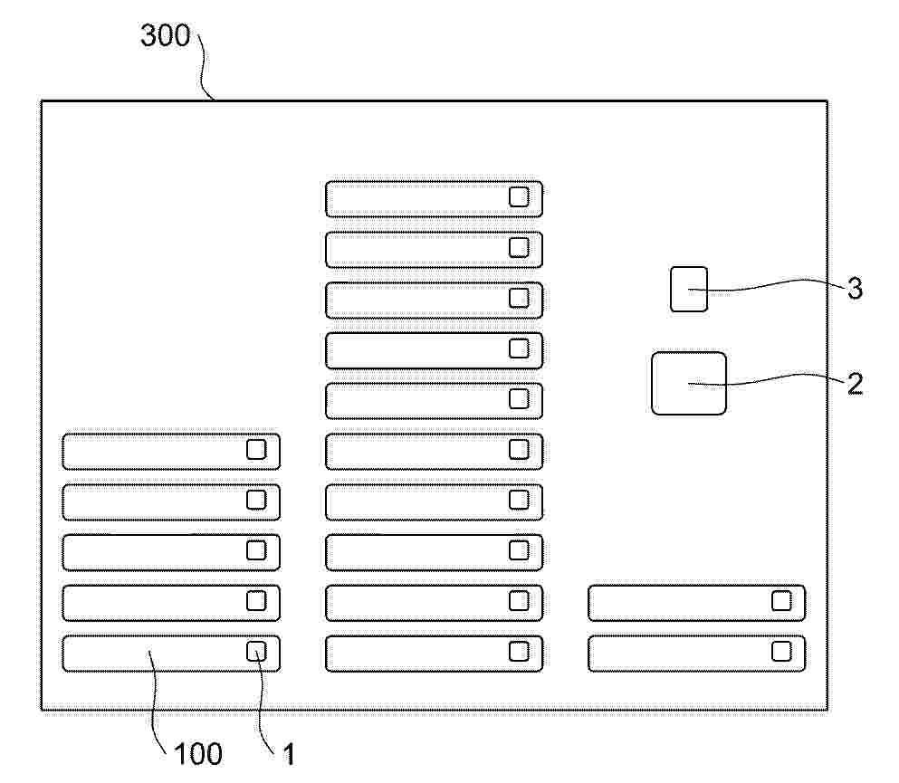
A battery cell, a battery device and an electric device. The battery cell comprises: a casing assembly (1); an electrode assembly (3) comprising a tab group (32) and an active material coating portion (31), wherein the tab group (32) comprises a welding portion (322); a terminal post assembly (2) arranged on a mounting wall (11) of the casing assembly (1) and comprising a terminal post body (21), wherein the terminal post body (21) has a first surface (21a) and a second surface (21b), which are opposite each other, the welding portion (322) is connected to the second surface (21b), and a second weld mark (6) of welding from the first surface (21a) towards the electrode assembly (3) is formed between the terminal post body (21) and the electrode assembly (3); and a support member configured to support the welding portion (322), such that the welding portion (322) is spaced apart from the active material coating portion (31).
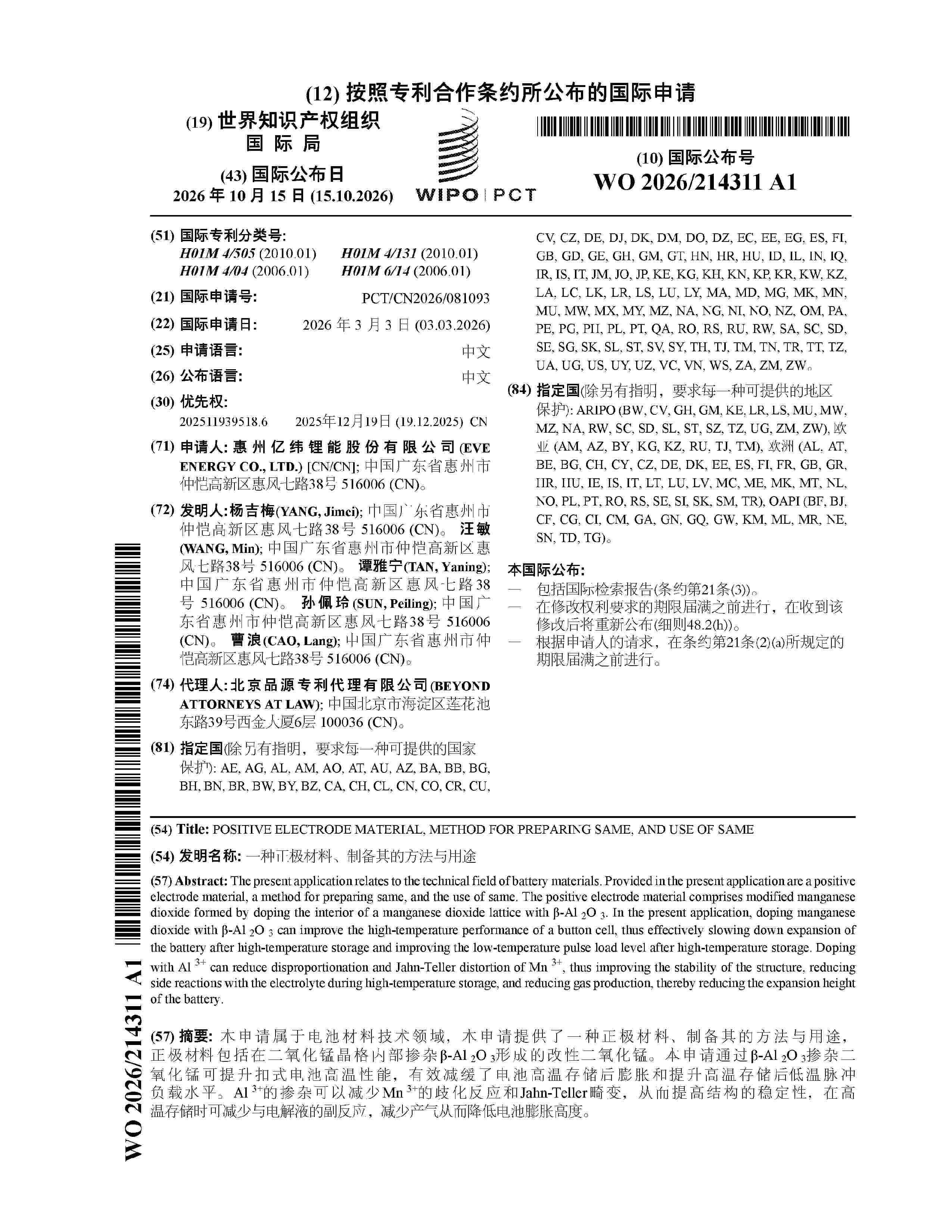
Resumen de: WO2026214311A1
The present application relates to the technical field of battery materials. Provided in the present application are a positive electrode material, a method for preparing same, and the use of same. The positive electrode material comprises modified manganese dioxide formed by doping the interior of a manganese dioxide lattice with β-Al 2O 3. In the present application, doping manganese dioxide with β-Al 2O 3 can improve the high-temperature performance of a button cell, thus effectively slowing down expansion of the battery after high-temperature storage and improving the low-temperature pulse load level after high-temperature storage. Doping with Al 3+ can reduce disproportionation and Jahn-Teller distortion of Mn 3+, thus improving the stability of the structure, reducing side reactions with the electrolyte during high-temperature storage, and reducing gas production, thereby reducing the expansion height of the battery.
Resumen de: DE102025114304A1
Es wird ein Verfahren zum Betrieb einer Hochvoltbatterie (100), insbesondere einer Traktionsbatterie eines Kraftfahrzeugs (200), vorgeschlagen, wobei ein Kommunikationsmodul (1) der Hochvoltbatterie (100) in regelmäßigen Zeitabständen drahtlos Informationen zum Zustand der Hochvoltbatterie (100) sendet.
Resumen de: WO2026214208A1
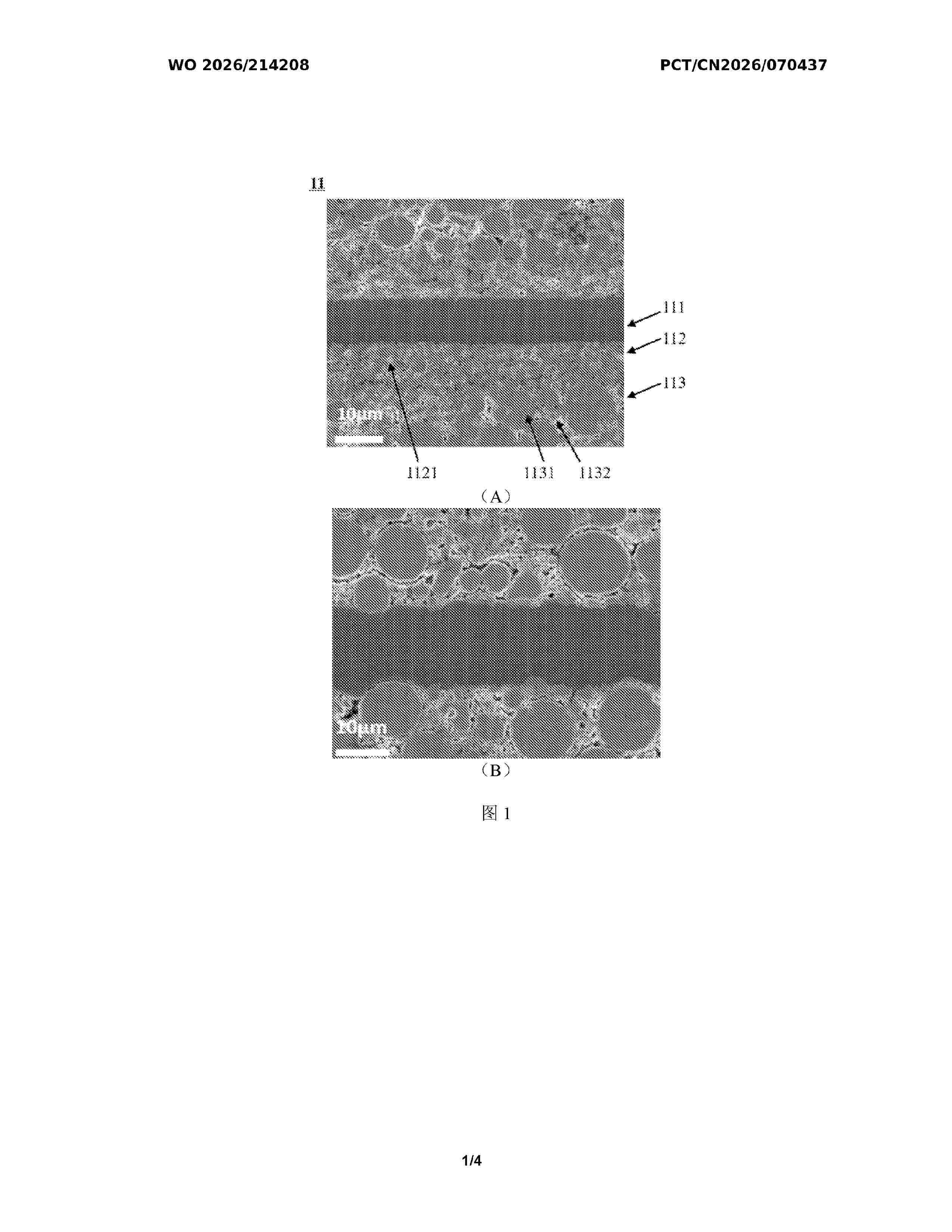
A battery cell. The battery cell comprises a positive electrode sheet. The positive electrode sheet comprises a positive electrode current collector, a positive electrode film layer arranged on at least one side of the positive electrode current collector, and a bottom coating located between the positive electrode current collector and the positive electrode film layer arranged on at least one side of the positive electrode current collector, wherein the positive electrode film layer comprises polycrystalline particles, the bottom coating comprises first single crystal particles, the volume particle size distribution Dv99 of the first single crystal particles ranges from 10 μm to 20 μm, the first single crystal particles comprise cobalt, and on the basis of the total number of moles of transition metals in the first single crystal particles, the molar ratio of cobalt in the first single crystal particles ranges from 4.5% to 10%.
Resumen de: WO2026216254A1
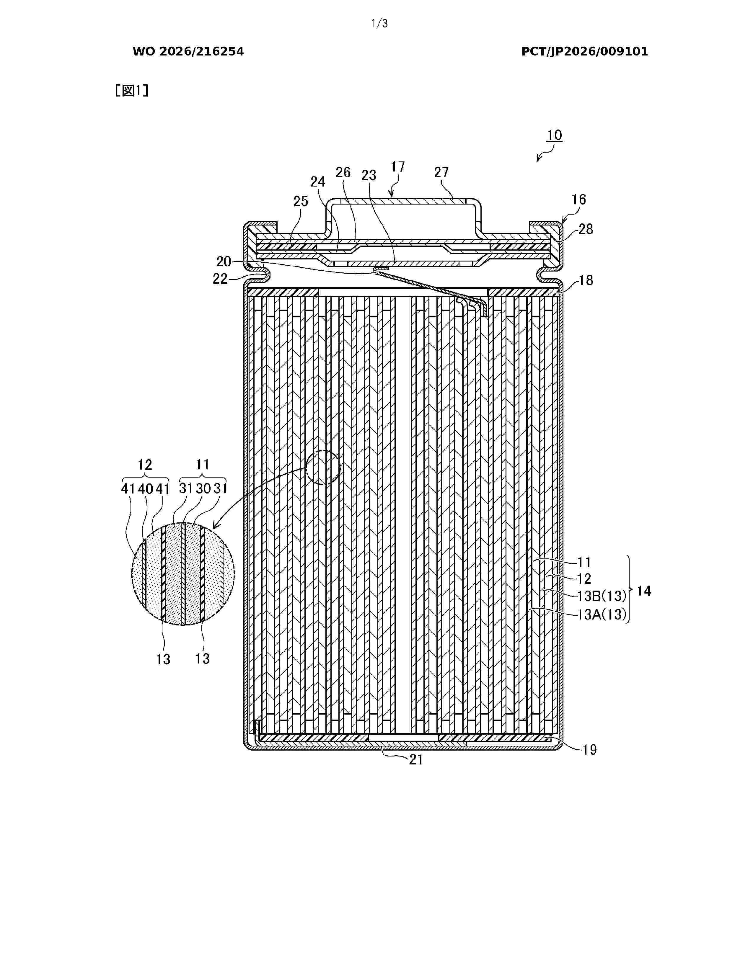
This invention is characterized by comprising: a winding mechanism (110) which has a rotatable winding core (111) and which winds a first electrode (11), a second electrode (12), and a separator (13) by rotation of the winding core (111); and a transport mechanism (120) that performs transport with respect to the winding core (111). This invention is also characterized in that: the transport mechanism (120) has a cutting device (131) that cuts the first electrode (11), and a transport device (133) that is disposed closer to the winding core (111) than the cutting device (131) and that transports the first electrode (11) to the winding core (111) by rotation of transport rollers (134); the transport device (133) is configured to enable adjustment of the position of the first electrode (11) in the width direction; and during at least a partial period when the first electrode (11) is wound, the speed at which the first electrode (11) is wound around the winding core (111) is made greater than the speed at which the first electrode (11) is transported by the transport device (133).
Resumen de: WO2026214237A1
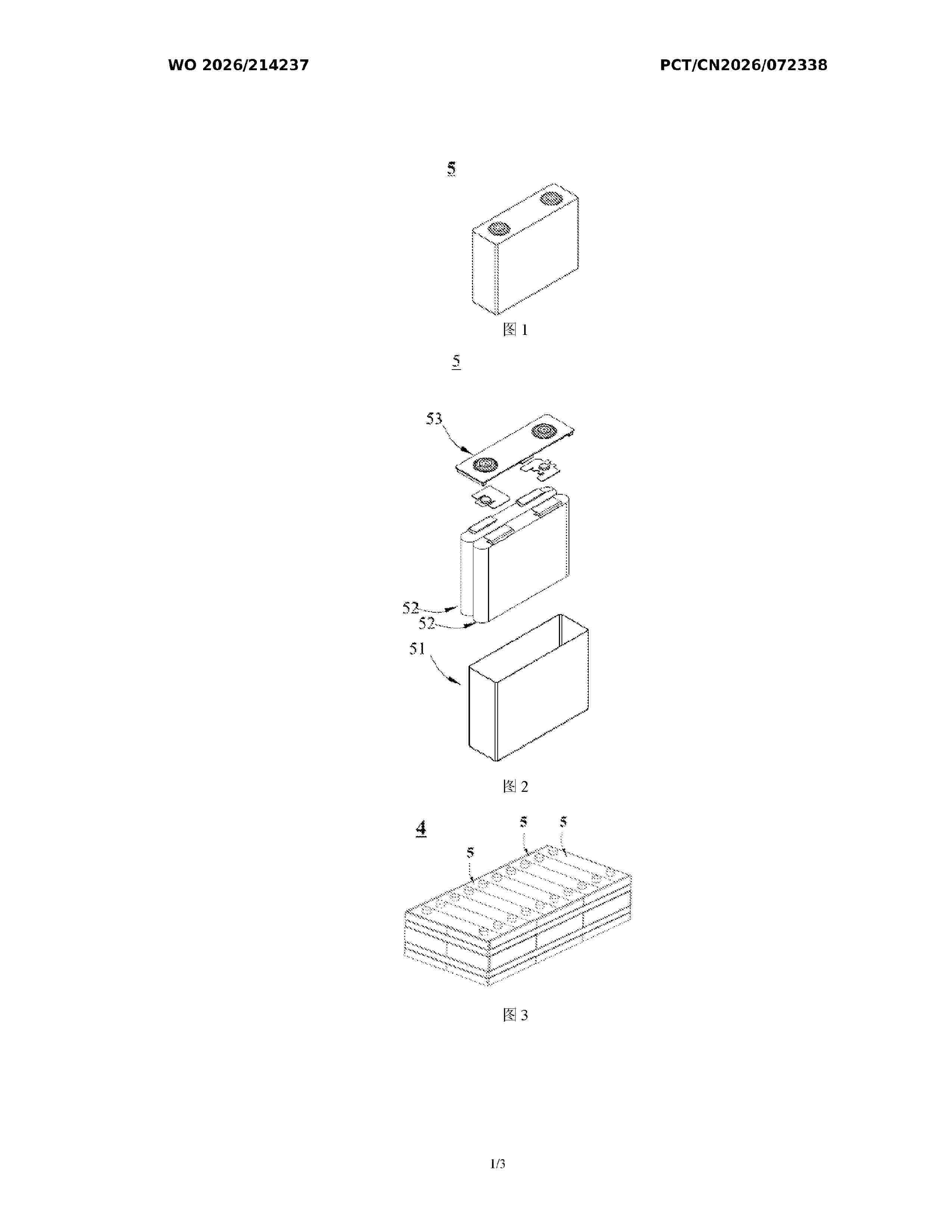
The present application provides a secondary battery and a manufacturing method therefor, and an electric device. The secondary battery comprises a negative electrode sheet. The negative electrode sheet comprises: a negative electrode current collector; and a negative electrode active material layer, the negative electrode active material layer being located on at least one side of the negative electrode current collector, and the porosity of the negative electrode active material layer being 35% to 45%.
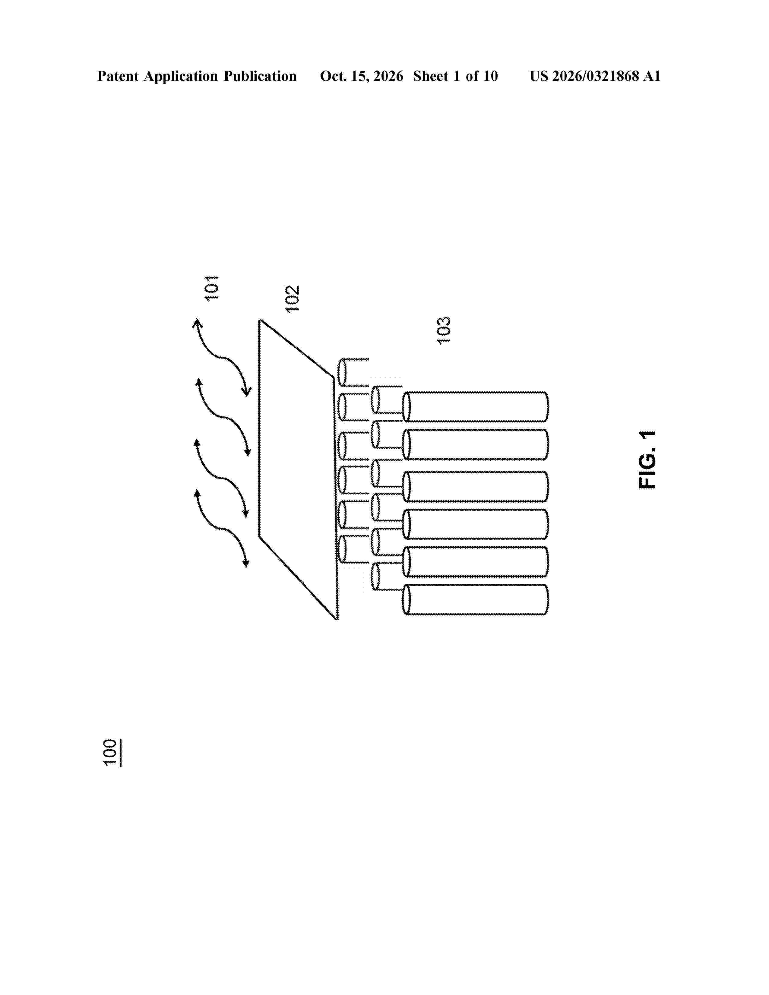
Resumen de: US20260321868A1
A pressure relief device is disclosed, such as may be used with a battery. According to one embodiment, the pressure relief device may comprise a flanged portion; a curved surface; and a line of weakness on the curved surface. The line of weakness may comprise a first end, a central line portion, and a second end, wherein at least one of the first end or the second end extends outside of a plane defined by the central line portion. The curved surface may have an aspect ratio greater than 1:1.
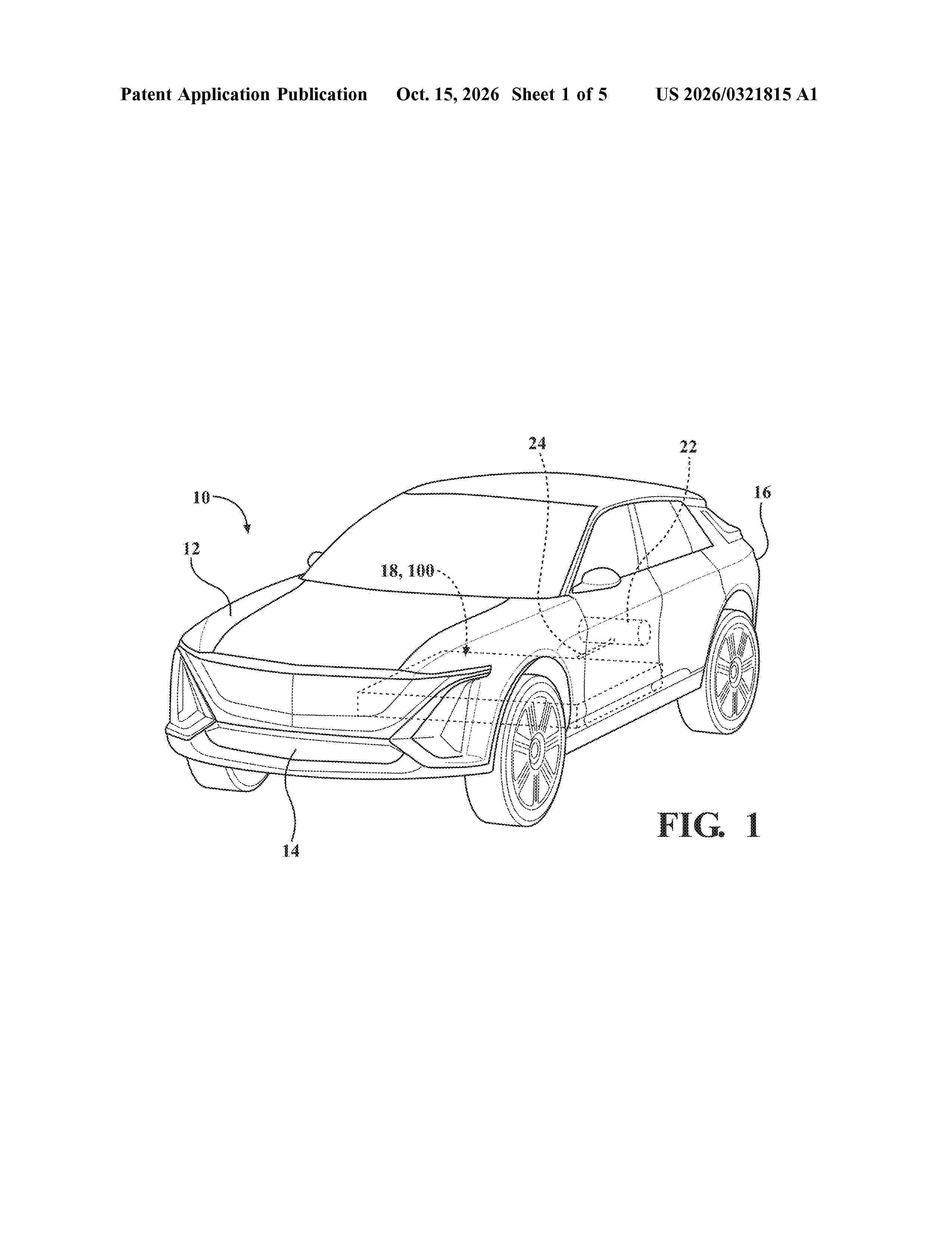
Resumen de: US20260321815A1
0000 A battery cell including an electrode that has a cathode, an anode, and a separator. The battery cell includes an inner enclosure at least partially surrounding the electrode assembly. The inner enclosure includes a shallow-drawn metallic housing having an inner surface that is at least partially coated with a first polypropylene (PP) layer, a closure member including a second PP layer that is sealed to the first PP layer of the shallow-drawn metallic housing, and at least one lead tab electrically connected to the electrode assembly and extending outwardly from the inner enclosure. The battery cell includes an outer enclosure surrounding at least a portion of the inner enclosure. The outer enclosure has a coating layer that includes aluminum tri-hydrate (ATH). The outer enclosure has a first region with a first thickness and a second region with a second thickness greater than the first thickness.
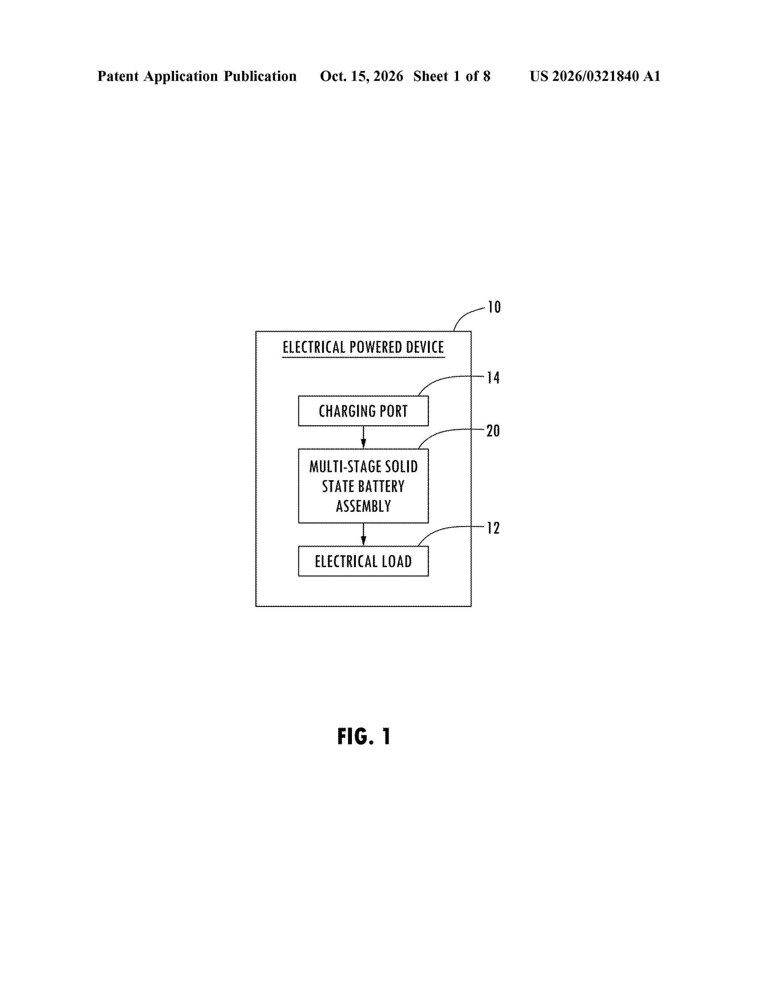
Resumen de: US20260321840A1
0000 A battery assembly including first and second end plate and a plurality of battery cells stacked between the first and second end plates. At least one first compression spring has a first spring travel distance, at least one second compression spring has a second spring travel distance that is less than the first spring travel distance, and at least one travel end stop is disposed proximate to the at least first compression spring and the at least second compression spring. A tension belt system is wrapped around the first and second end plates to provide stacked compression between the first and second end plates.
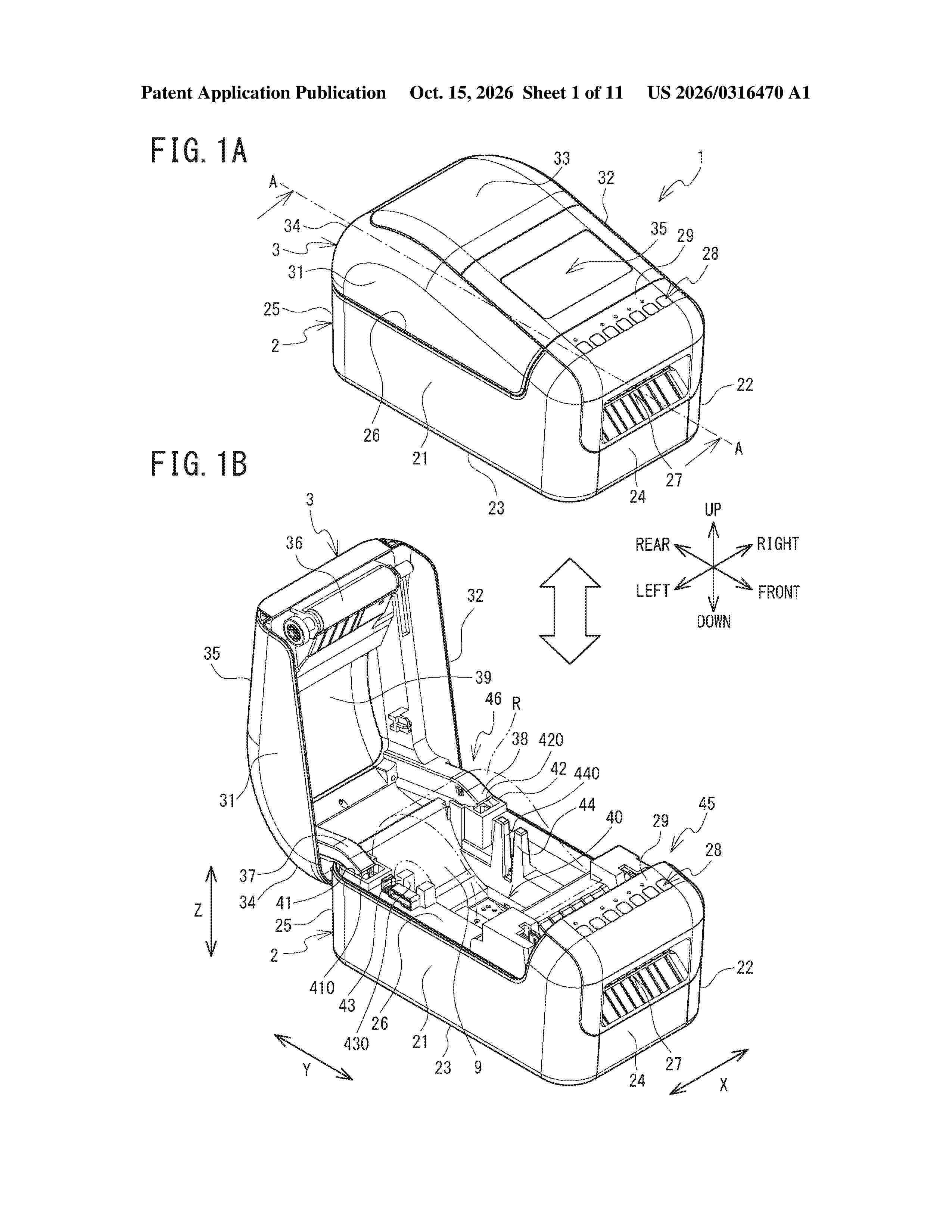
Resumen de: US20260316470A1
A printer includes a print head, a housing, and a battery housing portion. The print head extends in a main scanning direction. The housing including a first wall, a second wall, a lower wall, and a housing space. The first wall extends in a direction that crosses the main scanning direction. The second wall opposes the first wall. The lower wall connects the first wall and the second wall with each other in the main scanning direction. The housing space is defined between the first wall and the second wall and configured to house a print medium. The battery housing portion is included in the first wall of the housing and configured to house a coin cell battery.
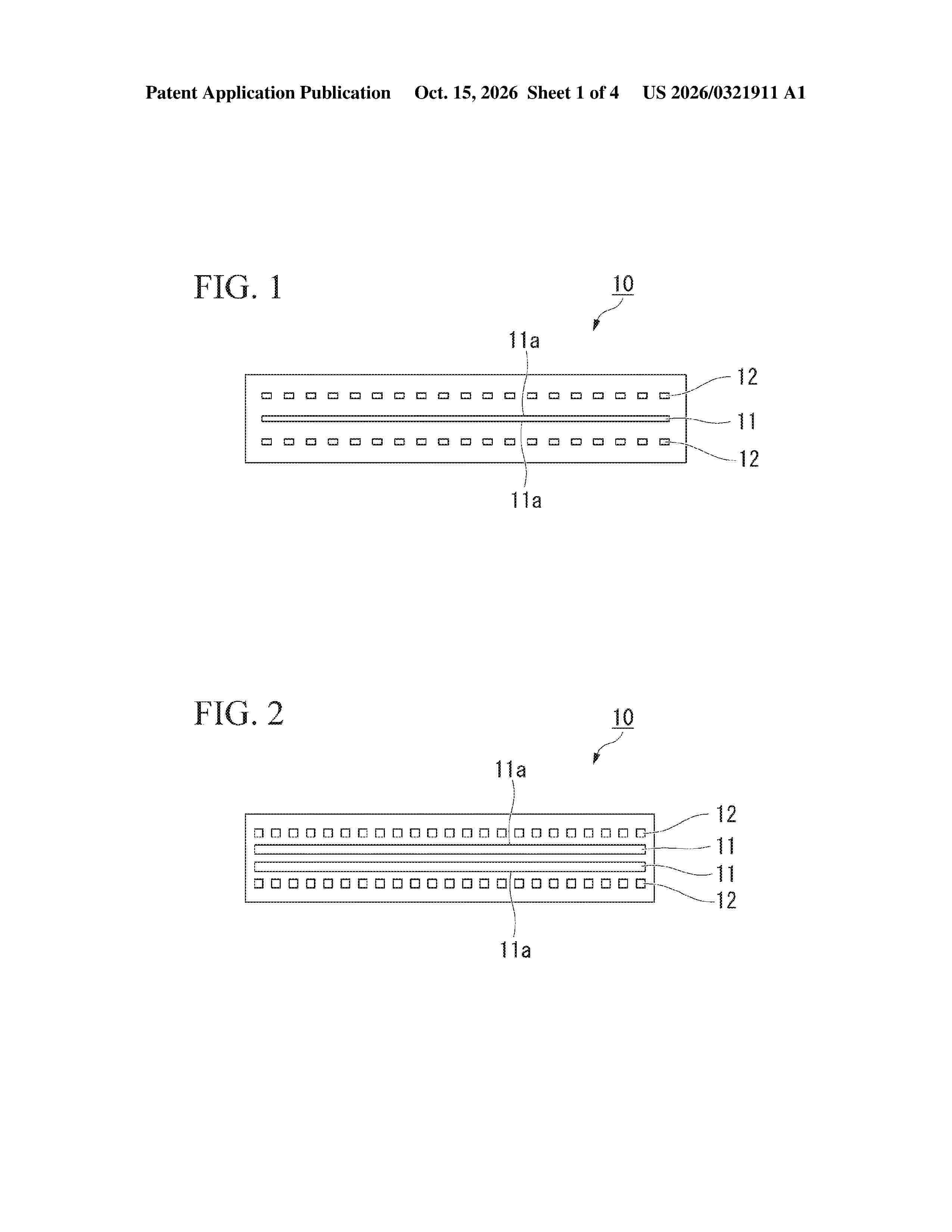
Resumen de: US20260321911A1
A battery includes: an electrode group including a positive electrode and a negative electrode; a plurality of current collector tabs electrically connected to the positive electrode or the negative electrode of the electrode group; and a tab lead joined to the plurality of current collector tabs, wherein a joint portion between the tab lead and a current collector tab of the plurality of current collector tabs has a first joint portion having a linear form and a second joint portion having a broken line form along a longitudinal direction of the current collector tab and the tab lead.
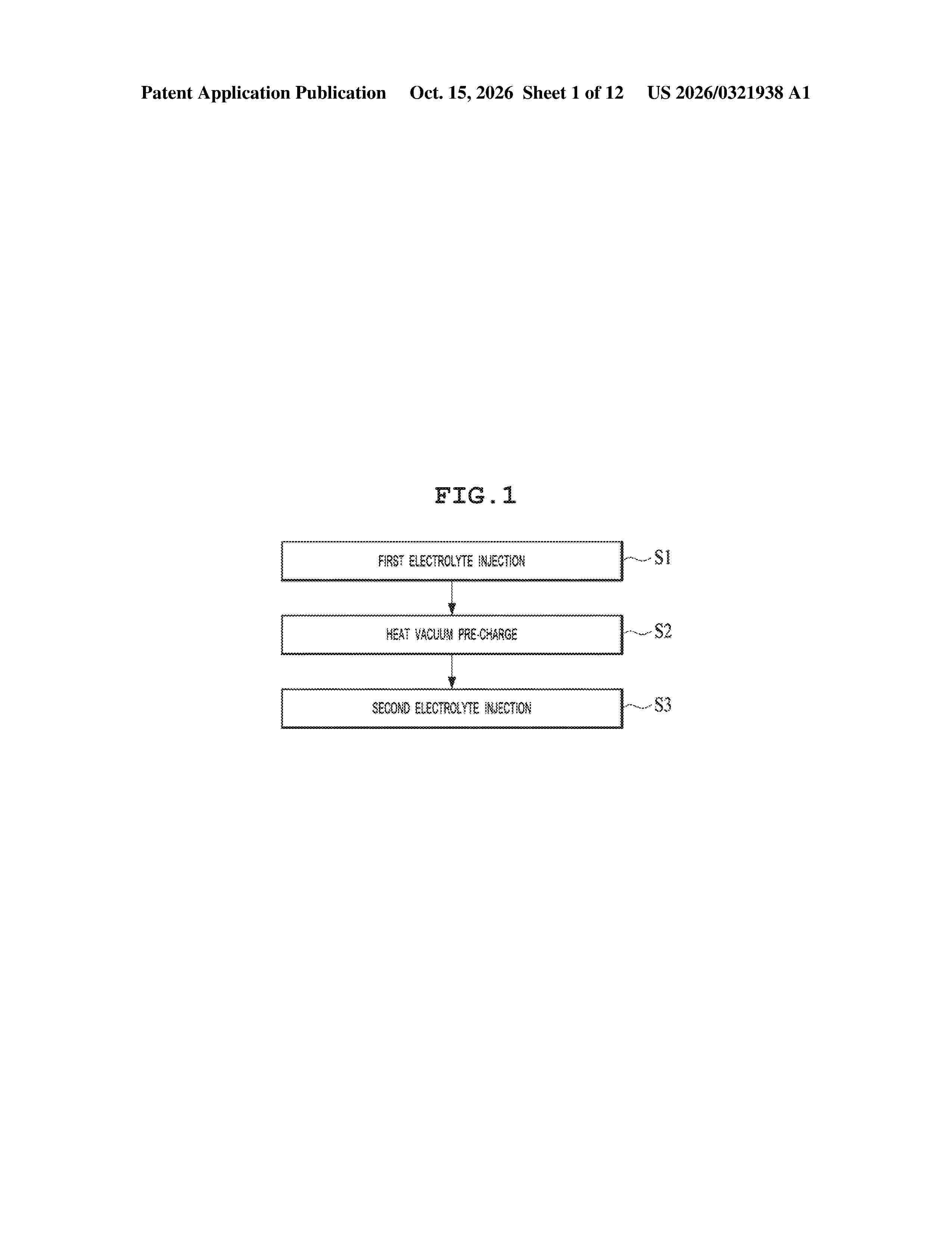
Resumen de: US20260321938A1
Proposed is an apparatus and method for injecting an electrolyte into a battery cell. The apparatus comprises at least one tray provided to receive a case with an electrode assembly inserted therein, at least one first hopper provided to inject the electrolyte into the case therethrough, at least one level sensor provided to measure the level of the electrolyte injected into the case, and a controller configured to be informed of the electrolyte level from the level sensors and to measure the degree of impregnation of the electrolyte by comparing the electrolyte level with a reference level.
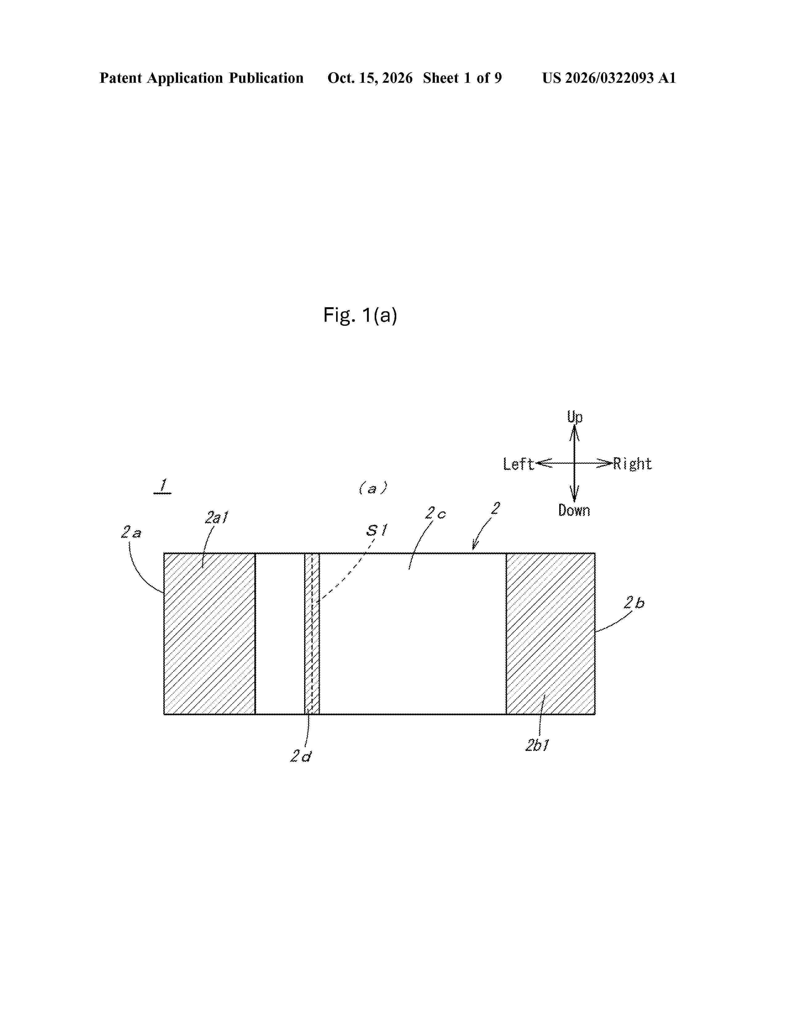
Resumen de: US20260322093A1
A flexible bus bar includes a flexible bus bar main body having flexibility; and a left fixing portion and a right fixing portion 2b1 for fixing both side portions of the flexible bus bar main body. When performing a bending process on the flexible bus bar main body at a bending line, a bending-specific fixing portion that includes the bending line is formed on the flexible bus bar main body in addition to the left fixing portion and the right fixing portion. The flexible bus bar that is capable of improving appearance and stabilizing the quality of a product.
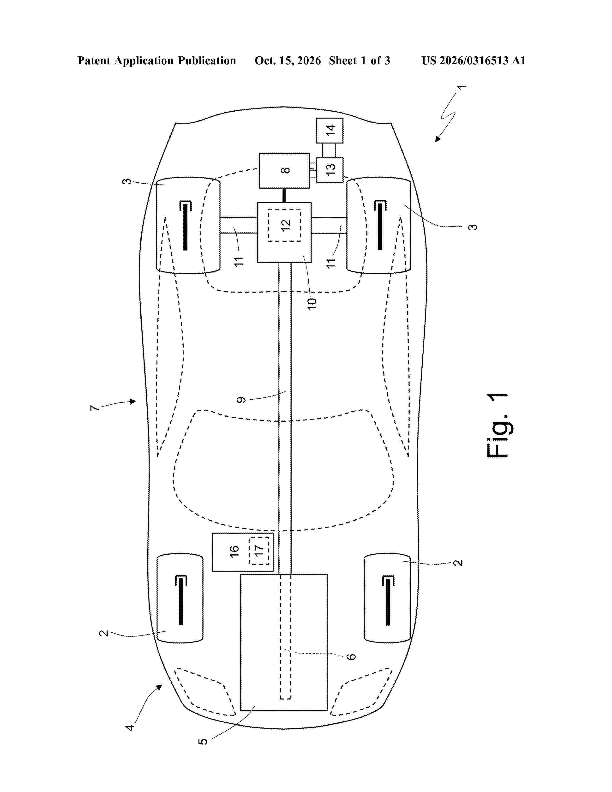
Resumen de: US20260316513A1
A storage system for an electric vehicle. The storage system is designed to store electrical energy and has at least one group of electrochemical pouch cells and a watertight container under pressure, which houses, on the inside, the group of electrochemical pouch cells. The group of electrochemical pouch cells is arranged inside a flexible, watertight casing inside which a vacuum is created. There is a compressor configured to maintain a pressure inside the container that is greater than atmospheric pressure.
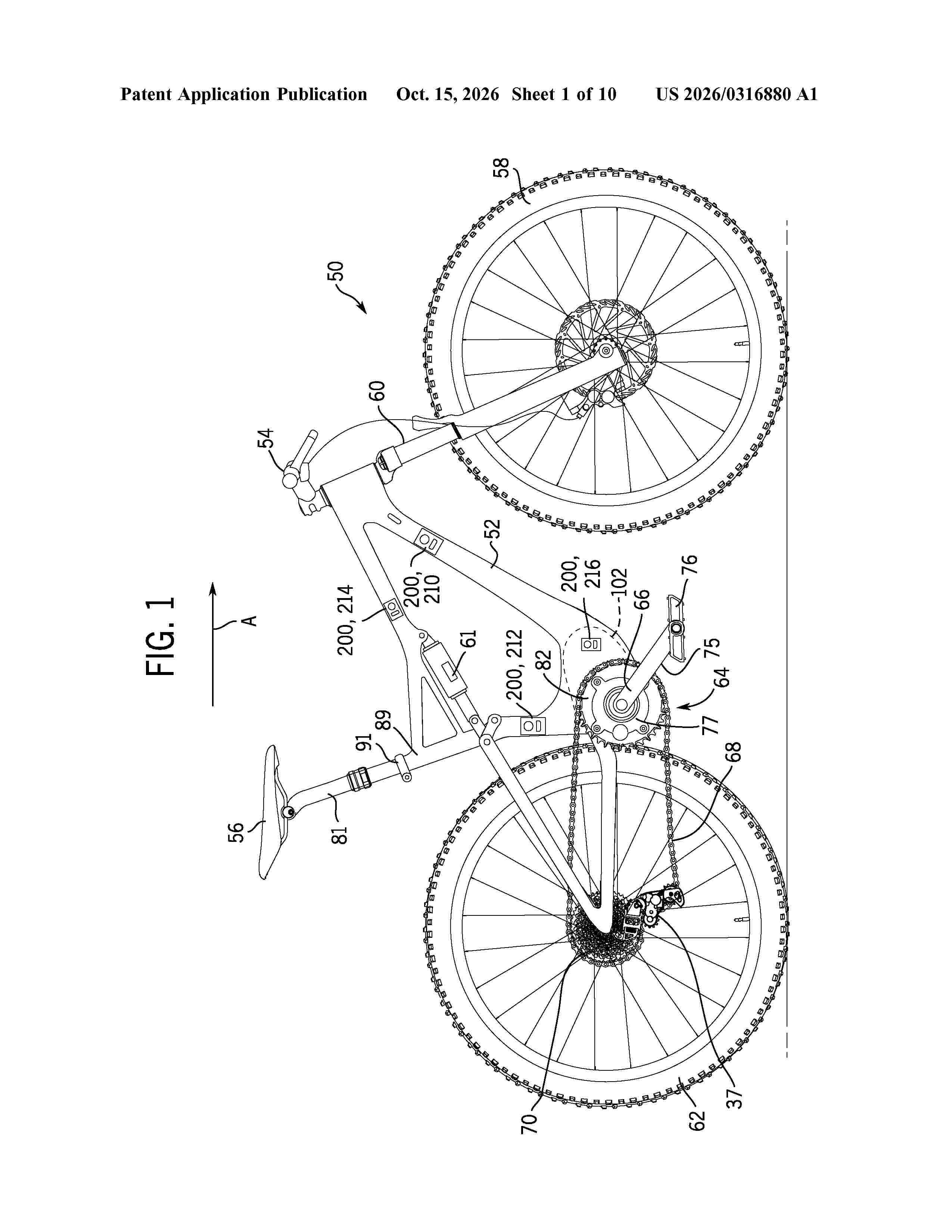
Resumen de: US20260316880A1
A system for an electric bicycle includes an energy storage device. The energy storage device includes a housing that is mountable to a frame of the electric bicycle, battery cells disposed within the housing, and output power terminals supported by the housing and electrically connectable to the battery cells. The energy storage device includes a processor and a first wireless communication device. The system includes a human/machine interface (HMI) electrically connected to the energy storage device via the output power terminals. The HMI includes a second wireless communication device. The processor is configured to change a mode of the energy storage device based on a signal received by the first wireless communication device from the second wireless communication device.
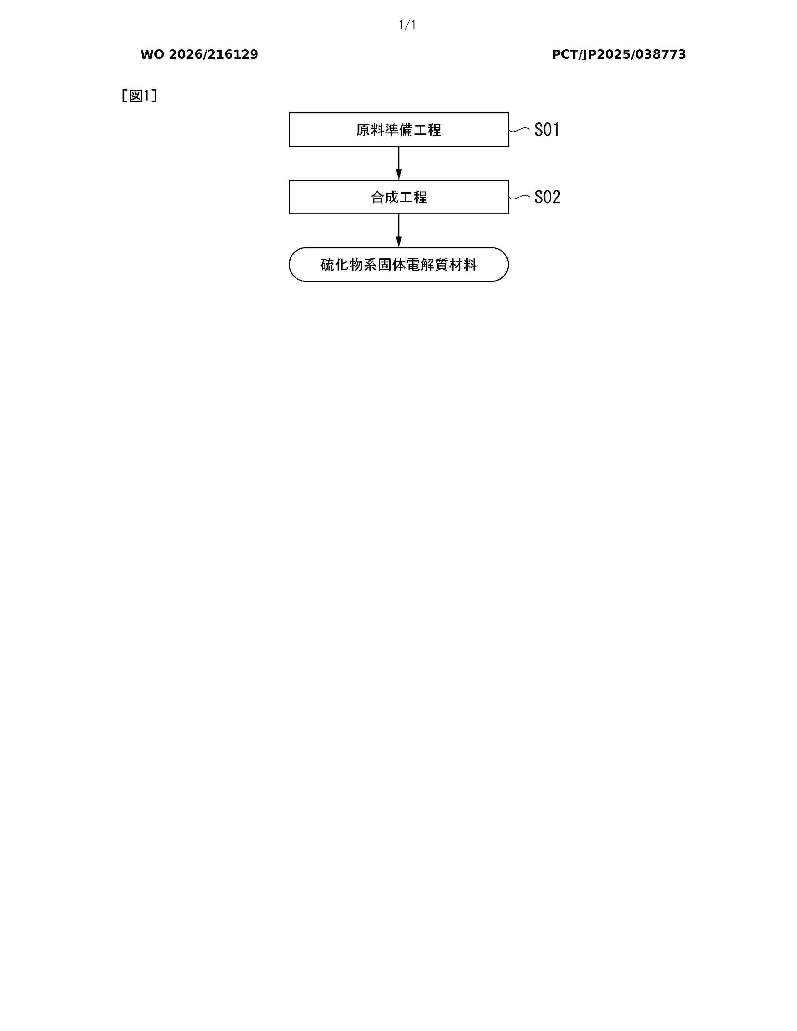
Resumen de: WO2026216129A1
This method for producing a sulfide-based solid electrolyte material comprises: a raw material preparation step (S01) for preparing an electrolyte raw material containing elements constituting the sulfide-based solid electrolyte material; and a synthesis step (S02) for synthesizing the sulfide-based solid electrolyte by heating the electrolyte raw material. In the raw material preparation step (S01), a sulfur raw material is blended such that the ratio of sulfur in the electrolyte raw material exceeds the stoichiometric ratio of a target composition. In the synthesis step (S02), the synthesis is performed in the presence of liquid-phase sulfur at the point when the electrolyte raw material has been heated to 400 °C.
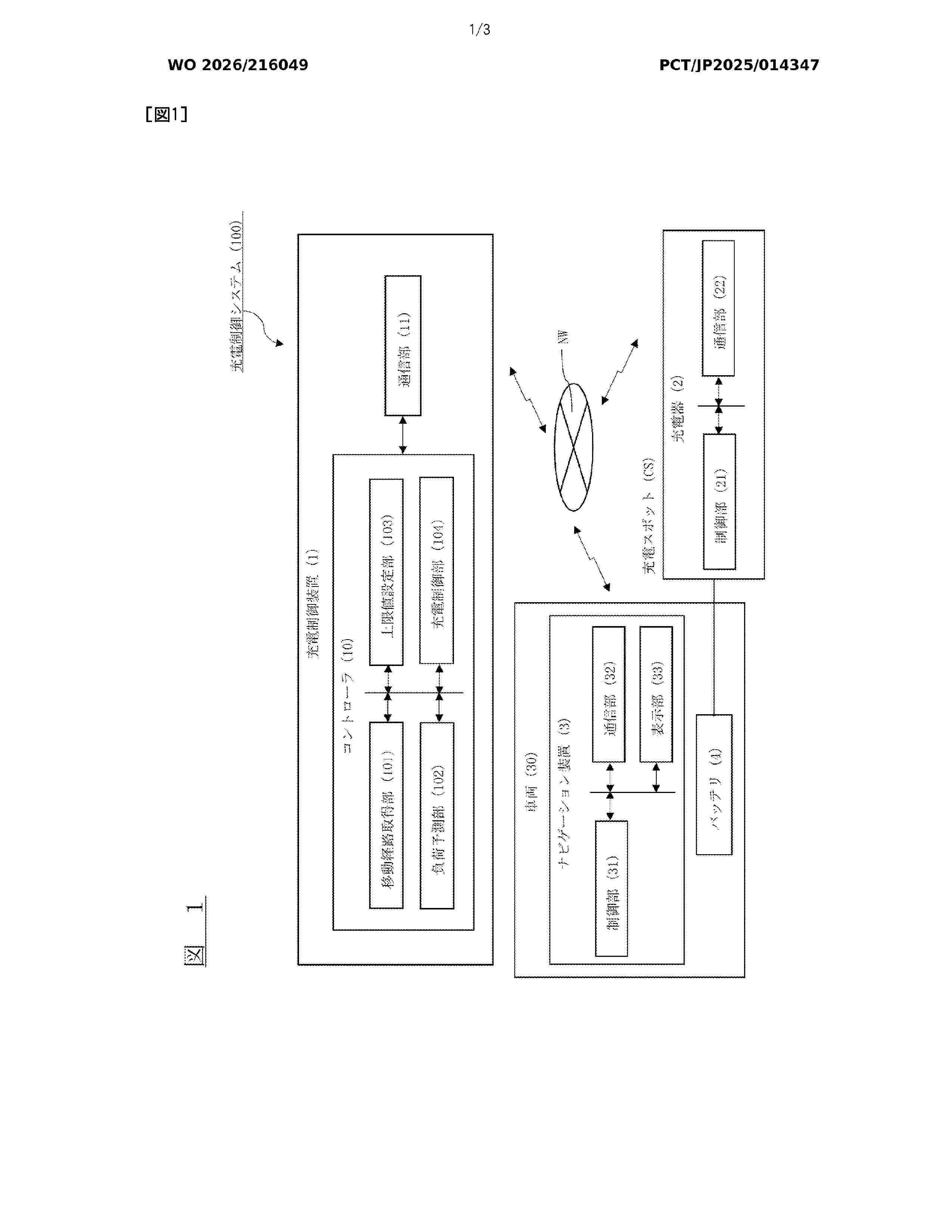
Resumen de: WO2026216049A1
This controller acquires a movement route from a charging spot through which a mobile body passes to a destination of the mobile body, and, if a movement load required for the mobile body to travel along the movement route is equal to or less than a predetermined threshold value, sets an upper limit of a charging control value at the charging spot to be higher than an upper limit set when the movement load is greater than the predetermined threshold value, and limits the charging control value on the basis of the upper limit.
Nº publicación: WO2026214217A1 15/10/2026
Solicitante:
CONTEMPORARY AMPEREX TECH CO LIMITED [CN]
\u5B81\u5FB7\u65F6\u4EE3\u65B0\u80FD\u6E90\u79D1\u6280\u80A1\u4EFD\u6709\u9650\u516C\u53F8
Resumen de: WO2026214217A1
A battery cell and a manufacturing method therefor, a secondary battery, and an electric device, relating to the technical field of secondary batteries. By controlling the roughness of a second coating to be greater than the roughness of a first coating, a capillary effect formed between the second coating and a negative electrode sheet is stronger than a capillary effect formed between the first coating and a positive electrode sheet, and an electrolyte wicking channel formed between the second coating and the negative electrode sheet is superior to an electrolyte wicking channel formed between the first coating and the positive electrode sheet, so that an electrolyte absorption rate on a negative electrode side is greater than an electrolyte absorption rate on a positive electrode side, thereby matching the requirements of the negative electrode sheet and the positive electrode sheet for an electrolyte, rapidly supplementing the electrolyte on the negative electrode side, fully utilizing the electrolyte, and improving the cycle performance of the secondary battery.
 BOPI
BOPI
 Sede Electrónica