Si deseas distinguir tus productos, servicios o ambos de los de otra empresa, es posible que necesites una marca o nombre comercial. Descubre qué son, en qué consiste su procedimiento de registro y qué implica.

Información sobre los plazos de presentación de solicitudes de transformación de marcas de la Unión Europea en marca nacional española. Más información


Si tienes un nuevo dispositivo, producto o procedimiento que resuelva un problema técnico o tenga una ventaja práctica, existen distintas formas de protegerlo en España y en otros países. Descubre cómo hacerlo.

¿Tu innovación reside en la estética, la ornamentación o la apariencia de tu producto? Protégela mediante un diseño industrial. Descubre qué derechos confiere el registro y cómo realizar la tramitación.

Las indicaciones geográficas protegen el nombre de un producto originario de una zona geográfica, a la cual le debe una determinada calidad, reputación u otra característica. Descubre qué son, en qué consiste su procedimiento de registro y qué beneficios conceden.

Las patentes publicadas en todo el mundo son una valiosa fuente de información científica, técnica y comercial.

Si eres emprendedor/a o una empresa y quieres potenciar y mejorar la rentabilidad de tu negocio protegiendo de forma adecuada los activos intangibles de tu organización, en este espacio encontrarás lo necesario.


 1318
resultados
1318
resultados
 Última actualización
15/03/2026 [07:37:00]
Última actualización
15/03/2026 [07:37:00]


 Resultados 525 a 550 de 1318

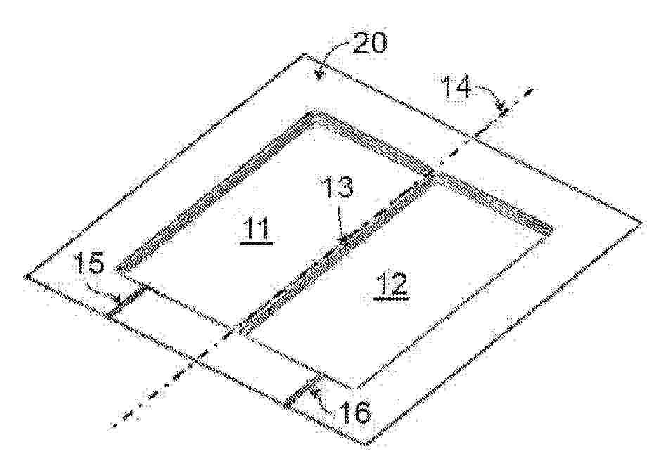
Resumen de: FR3165999A1
Procédé de fabrication d'une cellule en sachet comprenant les étapes suivantes: - formation, dans un film (20) multicouche, d'une première cavité (11) et d'une deuxième cavité (12), la première cavité et la deuxième cavité ayant un bord (13) en commun intégrant une ligne (14) de pliage permettant un rabattement de la première cavité (11) sur la deuxième cavité (12) de sorte à former un sachet apte à recevoir un empilement d'électrodes;- formation d'une première goulotte (15) semi-cylindrique dans le bord de la première cavité (11) et d'une deuxième goulotte (16) semi-cylindrique dans le bord de la deuxième cavité (12) de sorte que, lorsque la première cavité (11) est rabattue sur la deuxième cavité (12), la deuxième goulotte (16) forme avec la première (15) goulotte un conduit (17) apte à recevoir un câble s'étendant dans ledit sachet. Figure pour l’abrégé : Fig.2

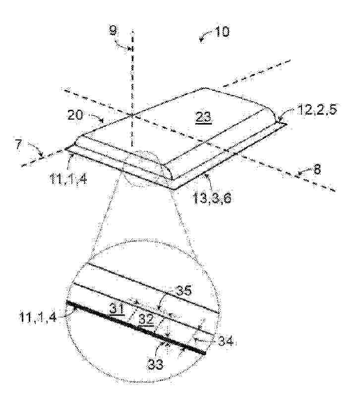
Resumen de: FR3166002A1
Cellule électrochimique comprenant :- une enveloppe comportant un premier et un deuxième logement formant un logement principal lorsque l’enveloppe extérieure est repliée autour d’un axe de pliage,le premier logement étant bordé transversalement par un premier bord et par un deuxième bord et parallèlement à l'axe de pliage par un troisième bord;le deuxième logement étant bordé transversalement par un quatrième bord et par un cinquième bord et parallèlement à l'axe de pliage par un sixième bord;- le premier bord et le quatrième bord étant solidaires selon une première jonction thermoscellée,- le deuxième bord et le cinquième bord étant solidaires selon une deuxième jonction thermoscellée,- le troisième bord et le sixième bord étant solidaires selon une troisième jonction thermoscellée;l’une au moins des jonctions comprenant une première portion d’une première épaisseur et une deuxième portion d’une deuxième épaisseur supérieure à la première épaisseur. Figure pour l’abrégé : Fig.2
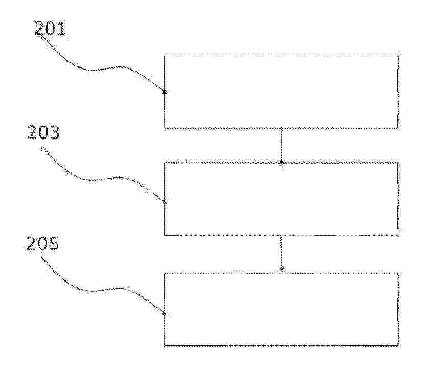
Resumen de: FR3165826A1
Un procédé de gestion de la charge électrique d’un véhicule automobile ayant une motorisation électrique alimentée par une batterie est mis en œuvre par un processeur et comprend les étapes de : recueil (201) des consommations électriques de la motorisation, des fonctions de confort et de la mise en température de charge de la batterie ;détermination (203) à partir des consommations électriques recueillies et de la charge restante de la batterie d’une distance maximale atteignable ;recherche (205) d’une station de recharge de la batterie se trouvant à une distance inférieure à la distance maximale atteignable. Un dispositif pour mettre en œuvre ce procédé et un véhicule automobile comprenant le dispositif sont également décrits. Figure à publier avec l’abrégé : Fig 2
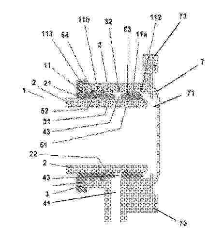
Resumen de: FR3165938A1
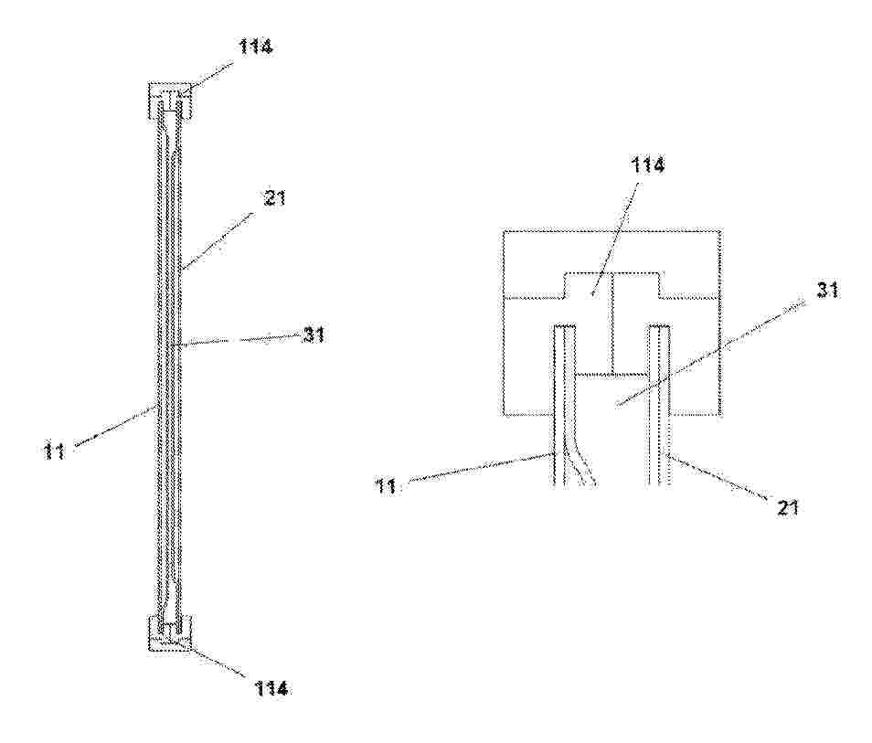
Mécanisme de jonction entre une extrémité de canalisation de type mâle et une extrémité de canalisation de type femelle L’invention concerne un système (1) de jonction pour la circulation d’un fluide entre un conduit mâle (2) et un conduit femelle (3) qui comprend : une première interface de connexion (21) réalisée par la surface extérieure du conduit mâle (2),une seconde interface de connexion (31) complémentaire à la première interface de connexion (21) et réalisée par la surface intérieure du conduit femelle (3),un dispositif intermédiaire élastique axial de jonction (11) comprenant au moins une surface respective (112, 113) en vis-à-vis de la première (21) et de la seconde (31) interface de connexion, pour être comprimé entre ces interfaces (21, 31), caractérisé en ce que : la seconde interface de connexion (31) comprend un orifice de drainage (41) vers un canal de drainage porté par le conduit femelle (3),le dispositif intermédiaire élastique axial de jonction (11) comprend, en vis-à-vis de la seconde interface de connexion (31), au moins deux lèvres ou séries de lèvres (51, 52) orthogonales à l’axe du dispositif (11), le dispositif intermédiaire de jonction (11) étant positionné en insertion dans le conduit femelle (31) de sorte que chaque lèvre ou série de lèvres (51, 52) est disposée de part et d’autre de l’orifice de drainage (41) de la seconde interface de connexion (31). Figure à publier avec l’abrégé : pas d
Resumen de: FR3166000A1
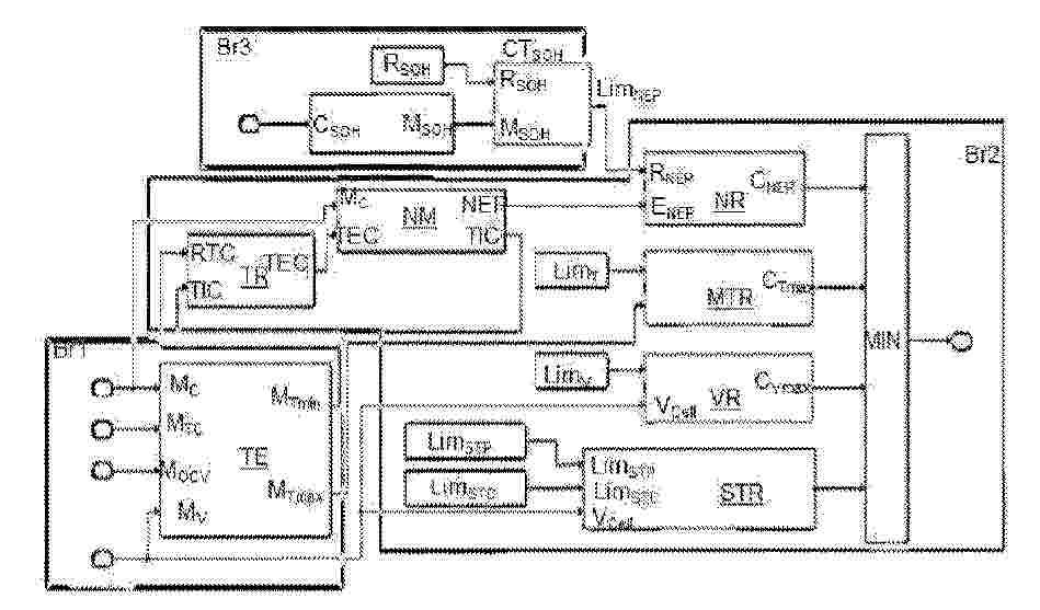
L’invention concerne un véhicule automobile comprenant une batterie équipée de cellules ayant au moins une électrode négative, et un contrôleur de batterie qui comprend :- des moyens de mesure de courant (MC) et de tension (MV) et de température (MTC) des cellules ;- un moyen d’estimation d’un potentiel d’électrode négative (NR) maximal à partir d’un modèle dudit potentiel (NM) en fonction du courant (MC) et de la température des cellules (MTC) ;- un moyen d’estimation de surchauffe (MTR) des cellules en fonction d’un seuil de température ; - un moyen d’estimation de surtension (VR) des cellules en fonction d’un seuil de tension ;- un moyen d’évaluation d’un courant de charge minimal (MIN) correspondant à la fois au seuil du potentiel d’électrode négative, au seuil de température, et au seuil de tension. L’invention concerne également un procédé et un programme sur la base d’un tel véhicule. Figure 2
Resumen de: FR3166011A1
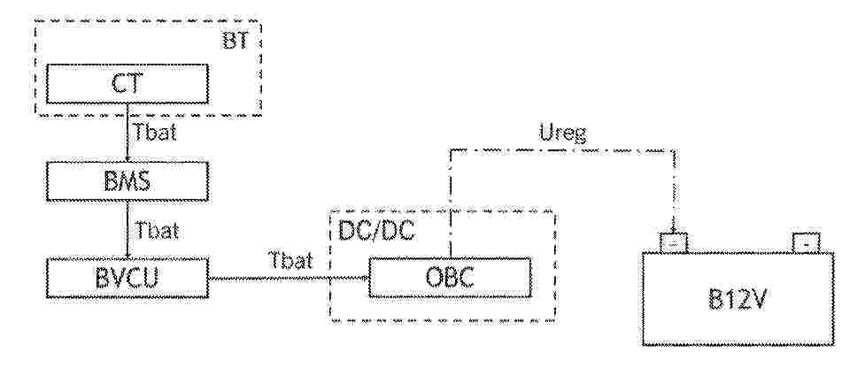
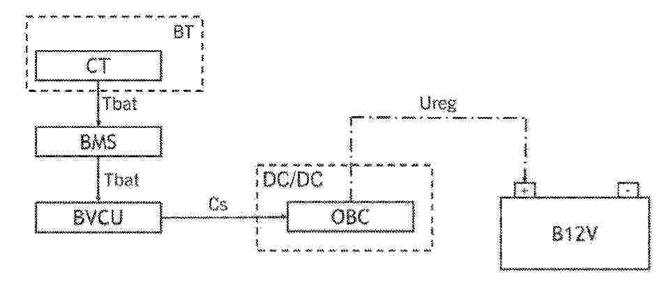
L’invention concerne un procédé de régulation d’une tension de sortie (Ureg) d’un convertisseur de tension continue-continue (DC/DC) d’un véhicule automobile comportant une étape de mesure de la température de la batterie 12V (B12V) par ledit capteur de température (CT), la température (Tbat) mesurée étant transmise vers l’unité de contrôle de la tension de la batterie (BVCU) ; une étape de transmission de la température (Tbat) depuis l’unité de contrôle de la tension de la batterie (BVCU) vers le chargeur embarqué (OBC) via une passerelle de communication ; et une étape de régulation de la tension de sortie (Ureg) émise par ledit chargeur embarqué (OBC) vers ladite batterie 12V (B12V), ladite tension de sortie (Ureg) étant déterminée en fonction de la température (Tbat) par le chargeur embarqué (OBC). Figure 1
Resumen de: FR3165896A1
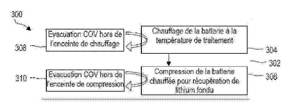
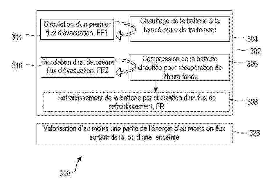
L’invention concerne un procédé (300) d’extraction de lithium d’une batterie électrique comprenant du lithium, ledit procédé (300) comprenant une phase (302) d’extraction de lithium, ladite phase d’extraction (302) comprenant les étapes suivantes réalisées, au moins en partie, dans au moins une enceinte : chauffage (304) de ladite batterie à une température, dite température de traitement, supérieure ou égale à la température de fusion du lithium métallique ; compression (306) de ladite batterie pour évacuer le lithium fondu hors de la batterie ; caractérisé en ce qu’il comprend, lors d’au moins une partie de ladite phase d’extraction (302), une évacuation (308,310) de composés organiques volatiles se trouvant dans ladite enceinte, ou au moins une desdites enceintes. Elle concerne également un système mettant en œuvre un tel procédé. Figure : Fig. 3
Resumen de: FR3165894A1
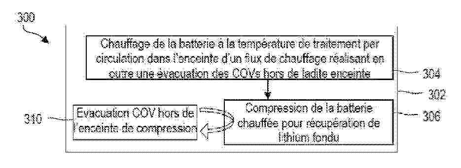
L’invention concerne un procédé (300) d’extraction de lithium d’une batterie électrique comprenant du lithium métallique, ledit procédé (300) comprenant une phase (302) d’extraction de lithium, ladite phase d’extraction (302) comprenant les étapes suivantes réalisées, au moins en partie, dans une enceinte : chauffage (304) de ladite batterie à une température, dite température de traitement, supérieure ou égale à la température de fusion du lithium métallique ; compression (306) de ladite batterie pour évacuer le lithium fondu hors de la batterie ; caractérisé en ce que l’étape de chauffage (304) est réalisée par circulation, dans ladite enceinte, d’un flux chaud, dit flux de chauffage, venant au contact de ladite batterie. Elle concerne également un système mettant en œuvre un tel procédé. Figure : Fig. 3
Resumen de: FR3166010A1
L’invention concerne un procédé de régulation d’une tension de sortie (Ureg) d’un convertisseur de tension continue-continue (DC/DC) d’un véhicule automobile, caractérisé en ce que ledit procédé comporte une étape de mesure de la température de la batterie de traction 48V (BT) par ledit capteur de température (CT) ; une étape de détermination d’une consigne (Cs) par l’unité de contrôle de la tension de la batterie (BVCU), ladite consigne (Cs) étant la valeur de tension de sortie (Ureg) appropriée pour la batterie 12V (B12V) en fonction de la température (Tbat) mesurée lors de ladite étape de mesure, ladite consigne (Cs) étant transmise au chargeur embarqué (OBC) et une étape de régulation de la tension de sortie (Ureg) émise par ledit chargeur embarqué (OBC) vers ladite batterie 12V (B12V), ladite tension de sortie (Ureg) étant égale à la consigne (Cs). Figure 1
Resumen de: FR3165827A1
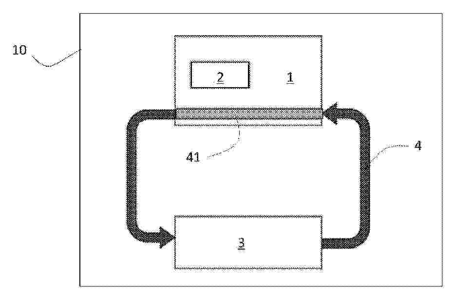
L’invention concerne un procédé de gestion de la température d’une batterie de traction (1) d’un véhicule automobile (10) comprenant un système de régulation thermique (3) de la batterie de traction, le procédé comportant des étapes de : mesure d’une température maximale à l’instant t de la batterie de traction, puis de comparaison avec au moins une température seuil parmi une température d’arrêt seuil « TempératureDArrêtDuCooling», une température d’activation seuil « TempératureDActivationDuCooling », une première température seuil « TemperatureStartDerating » et une deuxième température seuil « TemperatureNoPower », dans lequel, préalablement à l’étape de mesure, il comporte une réévaluation d’au moins l’une température seuil en fonction d’un état de santé instantanée à l’instant t de la batterie de traction (1) évalué par un système de gestion de la batterie (2) et d’un niveau de de vieillissement cible prédéfini à cet instant t. Figure 1
Resumen de: FR3165952A1
Module pour ensemble d’échanges thermiques avec des cellules de batteries La présente invention porte sur un module pour ensemble d’échanges thermiques avec au moins une cellule de batteries, comprenant au moins : une structure support d’au moins une cellule de batterie comprenant au moins un orifice formant un logement de forme complémentaire du bord périphérique de la au moins une cellule,un panneau d’échanges thermiques (11) positionné contre la structure support et comprenant un volume intérieur pour la circulation d’un fluide caloporteur entre au moins un orifice d’entrée et un orifice de sortie du fluide, caractérisé en ce que le panneau d’échanges thermiques est réalisé par au moins deux structures de forme sensiblement plane positionnées en vis-à-vis l’une de l’autre et assemblées entre elles par leurs bords périphériques de sorte que l’étanchéité du volume intérieur du panneau d’échanges thermiques est opérée par une soudure périphérique entre les deux structures. Figure à publier avec l’abrégé : Fig. 8
Resumen de: FR3165895A1
L’invention concerne un procédé (300) d’extraction de lithium d’une batterie électrique comprenant une phase (302) d’extraction, réalisée, au moins en partie, dans une ou plusieurs enceintes et comprenant les étapes de : chauffage (304) de ladite batterie à une température de traitement supérieure ou égale à la température de fusion du lithium métallique ; compression (306) de ladite batterie pour évacuer le lithium fondu hors de la batterie ; ladite phase d’extraction (302) comprenant en outre une circulation d’un flux dans ladite enceinte, ou dans au moins une desdites enceintes ; ledit procédé (300) comprenant en outre une valorisation (320) d’au moins une partie de l’énergie du flux sortant de ladite enceinte. Elle concerne également un système mettant en œuvre un tel procédé. Figure : Fig. 3
Resumen de: FR3166004A1
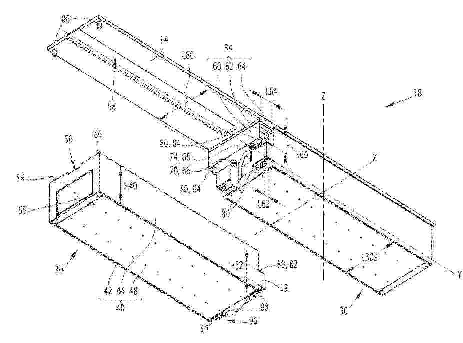
Système de batteries pour véhicule électrique ou hybride La présente invention concerne un système de batteries (18), pour véhicule électrique ou hybride, comprenant des modules de batterie (30), comportant un boîtier (40) s’étendant perpendiculairement à un axe vertical (Z), des cellules électrochimiques (32) et une plaque terminale (50) fermant le boîtier ; et un système de refroidissement (34) ayant un châssis (60) fixé au sol du véhicule, un conduit d’entrée (62) et un conduit de sortie (64). Des raccords fluidiques d’entrée (66) et de sortie (68) sont respectivement associés aux plaques terminales et s’étendent entre le châssis et les plaques terminales, parallèlement ou obliquement à l’axe vertical, pour les relier aux conduits d’entrée et de sortie et permettre la circulation d’un fluide réfrigérant dans les modules de batterie. Des éléments de fixation (80) fixent les plaques terminales au châssis en s’étendant parallèlement ou obliquement à l’axe vertical entre les plaques terminales et le châssis. Figure pour l'abrégé : 2
Resumen de: FR3166003A1
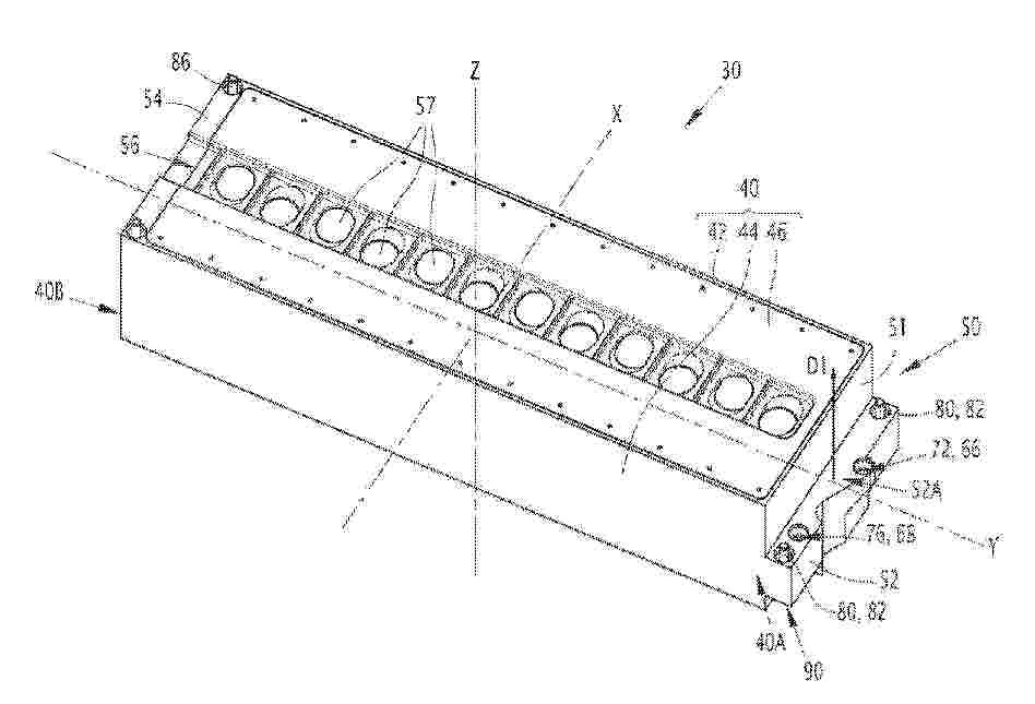
MODULE DE BATTERIE POUR UN SYSTÈME DE BATTERIES D’UN VÉHICULE ÉLECTRIQUE OU HYBRIDE ET SYSTÈME DE BATTERIES ASSOCIÉ La présente invention concerne un module de batterie (30), pour un système de batteries d’un véhicule électrique ou hybride, comprenant un boîtier (40) tubulaire, une première plaque terminale (50) et une deuxième plaque terminale (54) fermant les extrémités (40A, 40B) du boîtier, et des cellules électrochimiques disposées dans le boîtier. La première plaque terminale comprend un corps (51) ; un canal d’entrée (65A) et un canal de sortie (65B), ménagés dans le corps et permettant une circulation de fluide réfrigérant dans le module de batterie entre le canal d’entrée et le canal de sortie pour refroidir les cellules électrochimiques ; une borne positive (88A) et une borne négative (88B), fixées au corps, électriquement connectées aux cellules électrochimiques et s’étendant hors du boîtier ; et des organes de fixation (85), disposés dans le corps et permettant la fixation du module de batterie au véhicule. Figure pour l'abrégé : 3
Resumen de: FR3166001A1
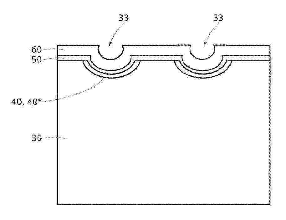
Titre : Dispositif de stockage et procédé de fabrication L’invention concerne un procédé de réalisation d’une électrode d’une batterie solide comprenant au moins les étapes suivantes : une réalisation d’une électrode (30) sur un support, l’électrode (30) présentant une face supérieure (31) opposée au support, l’électrode (30) présentant au moins une cavité (33) s’étendant en creux depuis sa face supérieure (31), une formation d’une couche ioniquement isolante, dite couche barrière (40), sur la face supérieure (31) de l’électrode (30) et dans l’au moins une cavité (33), puis un retrait de la couche barrière (40) de sorte à mettre à découvert la face supérieure (31) de l’électrode (30), tout en laissant en place la portion de la couche barrière (40) s’étendant dans l’au moins une cavité (33). Figure pour l’abrégé : Fig.5C
Resumen de: FR3165835A1
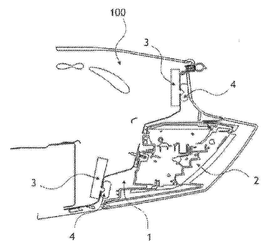
L’invention concerne un véhicule (100) automobile électrique ou hybride comportant une batterie, ledit véhicule (100) comportant un conduit de remplissage joint à ladite batterie, ledit conduit de remplissage comportant une ouverture, ledit conduit de remplissage étant destiné à recevoir et à guider un fluide vers ladite batterie, ledit véhicule (100) comportant au moins un logement (1) configuré pour contenir un phare (2), ladite ouverture étant accessible depuis ledit logement (1), caractérisé en ce que ledit véhicule (100) comporte au moins un moyen d’éjection configuré pour éjecter ledit phare (2) en dehors dudit logement (1). En outre, l’invention concerne un procédé d’éjection du phare (2) en dehors du logement du véhicule (100) automobile électrique ou hybride. Figure. 1
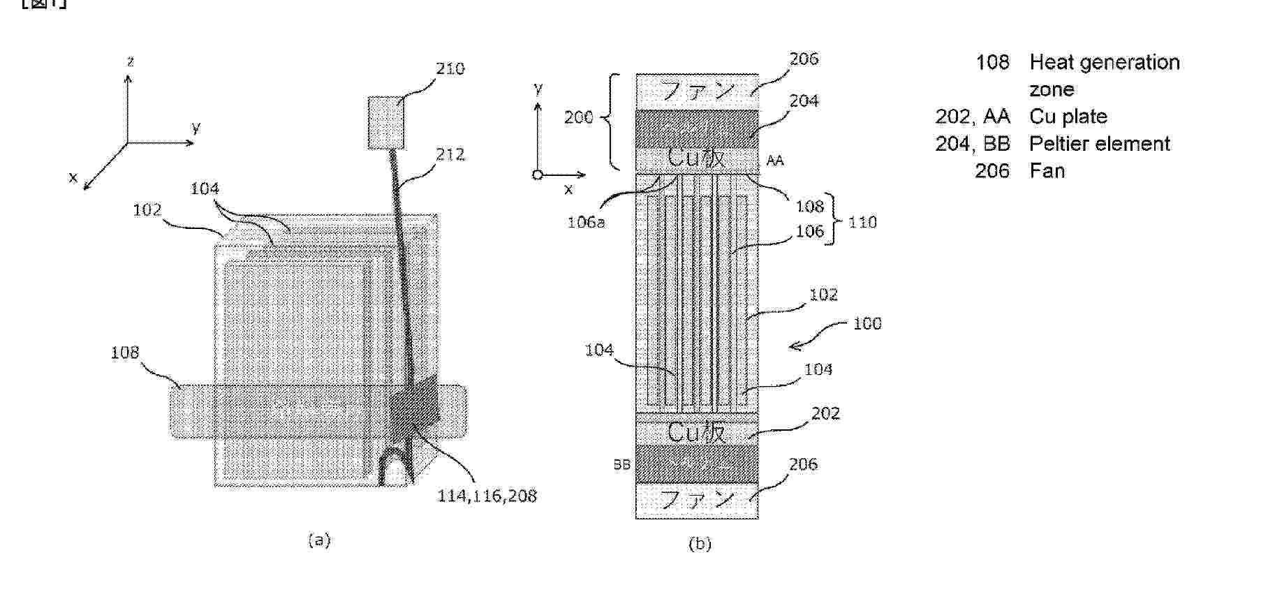
Resumen de: WO2026049036A1
Problem To provide a rapid-charging battery unit for use in an electric motorcycle, other electric light vehicles, and an electric robot, and an indoor installable charging station capable of charging the rapid-charging battery unit. Solution The rapid-charging battery unit comprises: a battery case inside which a plurality of rechargeable sheet-shaped battery cells is arranged side by side and sealed with positive and negative terminals thereof being connected in series/parallel by conductive busbars; and a plate-shaped heat absorption/dissipation means made of copper, aluminum, or graphite resin that is positioned to have heat absorption sections arranged in parallel and inserted in a layered configuration between the outer surfaces of the battery cells in a region on the charging side of each battery cell and/or arranged in parallel at the outer surfaces of the outermost battery cells, and a heat dissipation section connected to the edges of the heat absorption sections and exposed to the outside.
Resumen de: WO2026049034A1
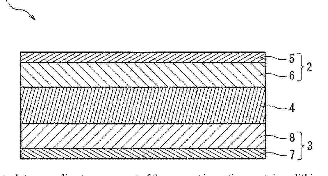
A solid electrolyte according to one aspect of the present invention contains a lithium element, a phosphorus element, a silicon element, a sulfur element, and a halogen element, and has a crystal structure, in which the molar ratio (Si/(P+Si)) of the content of the silicon element to the total content of the phosphorus element and the silicon element is 0.25-0.85 inclusive, the molar ratio (X/(P+Si)) of the content of the halogen element to the total content of the phosphorus element and the silicon element is 0.35 or more, and the halogen element does not contain a chlorine element, or the halogen element contains the chlorine element and the molar ratio (Cl/(P+Si)) of the content of the chlorine element to the total content of the phosphorus element and the silicon element is 0.30 or less.
Resumen de: WO2026049033A1
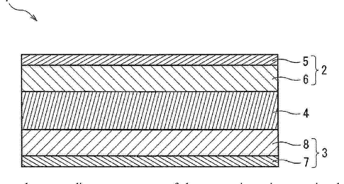
A solid electrolyte according to one aspect of the present invention contains, as constituent elements, lithium, phosphorus, silicon, sulfur, and X, with X being bromine and iodine, wherein: the molar ratio (Si/(P+Si)) of the content of silicon to the total content of phosphorus and silicon is 0.10-0.50; the molar ratio (X/(P+Si)) of the content of X to the total content of phosphorus and silicon is 0.40-0.80; and the molar ratio (Br/(P+Si)) of the content of bromine to the total content of phosphorus and silicon is 0.22-0.47.
Resumen de: WO2026049031A1
A solid electrolyte according to one aspect of the present invention comprises elemental lithium, elemental phosphorus, elemental silicon, elemental sulfur, and a halogen element, wherein the halogen element includes at least one of elemental bromine and elemental iodine, and expression (1), expression (2A), and expression (3) are satisfied. In expression (1), expression (2A), and expression (3), P, Si, S, and X are the mole-based content of the elemental phosphorus, the elemental silicon, the elemental sulfur, and the halogen element, respectively, in the solid electrolyte. Expression (1): 0.25≤Si/(P+Si)≤0.45 Expression (2A): 3.75≤S/(P+Si)≤4.03 Expression (3): 0.40≤X/(P+Si)
Resumen de: WO2026049030A1
A solid electrolyte according to one aspect of the present invention contains, as constituent elements, lithium, phosphorus, M, sulfur, and a halogen, with M being at least one element selected from the group consisting of silicon, germanium, and tin, wherein in an X-ray diffraction pattern obtained by using CuKα radiation, a diffraction peak A is observed within the diffraction angle 2θ range of 20.1°±0.3°, a diffraction peak B is observed within the diffraction angle 2θ range of 29.4°±0.3°, and a diffraction peak C is observed within the diffraction angle 2θ range of 33.3°±0.3°; and formula (1) and formula (2A) are satisfied. In formula (1) and formula (2A), P, M, and S are contents on a molar basis of phosphorus, M, and sulfur in the solid electrolyte, respectively. (1): 0.12 ≤ M/(P+M) ≤ 0.45 (2A): 0.94 ≤ S/4(P+M) ≤ 1.00
Resumen de: WO2026049027A1
A solid electrolyte according to one aspect of the present invention contains a lithium element, a phosphorus element, a tin element, a sulfur element, and an element X, wherein the element X is a bromine element and an iodine element, a molar ratio (Sn/(P+Sn)) of the content of the tin element to the total content of the phosphorus element and the tin element is 0.15 to 0.45, a molar ratio (S/(P+Sn)) of the content of the sulfur element to the total content of the phosphorus element and the tin element is 3.70 to 4.10, and a molar ratio (X/(P+Sn)) of the content of the element X to the total content of the phosphorus element and the tin element is 0.10 to 1.00.
Resumen de: WO2026049029A1
A solid electrolyte according to one aspect of the present invention contains the element lithium, the element phosphorus, an element M, the element sulfur, and an element X, wherein the element M is at least one selection from the group consisting of the element silicon, the element germanium, and the element tin, and the element X is at least one selection from the group consisting of the element bromine and the element iodine. In an X-ray diffraction diagram of the solid electrolyte obtained using CuKα radiation, a diffraction peak A is present in the range of diffraction angle 2θ = 20.1° ± 0.3°, a diffraction peak B is present in the range of diffraction angle 2θ = 29.4° ± 0.3°, and a diffraction peak C is present in the range of diffraction angle 2θ = 33.3° ± 0.3°. The ratio IC/IB in the X-ray diffraction diagram of the intensity IC of the diffraction peak C to the intensity IB of the diffraction peak B is at least 0.15. The X-ray diffraction diagram either does not have a diffraction peak in the range of diffraction angle 2θ = 24.9° ± 0.3° or has a diffraction peak D in the range of diffraction angle 2θ = 24.9° ± 0.3° with the ratio ID/IB of the intensity ID of the diffraction peak D to the intensity IB of the diffraction peak B being not more than 0.05.
Resumen de: WO2026049016A1
A solid electrolyte according to one aspect of the present invention contains elemental lithium, elemental phosphorus, elemental silicon, elemental sulfur, and a halogen element. The molar ratio of the elemental silicon content to the total elemental phosphorus and silicon content (Si/(P+Si)) is 0.12 or greater. The halogen element contains elemental bromine and/or elemental iodine, and the molar ratio of the total elemental bromine content and the elemental iodine and halogen element content ((Br+I)/X) is 0.30 or greater. In an X-ray diffraction pattern (CuKα), diffraction peaks are present across a diffraction angle 2θ of 20.0° ± 0.5° and across a diffraction angle 2θ of 29.3° ±0.5°. In the X-ray pattern, either no diffraction peak is not present across a diffraction angle 2θ of 17.5° ±0.5°, or a diffraction peak is present across a diffraction angle 2θ of 17.5° ±0.5°, and the intensity of the diffraction peak across the diffraction angle 2θ of 17.5° ± 0.5° is equal to or less than 1/5 the intensity of the diffraction peak across the diffraction angle 2θ of 20.0°± 0.5°.
Nº publicación: WO2026049014A1 05/03/2026
Solicitante:
GS YUASA INT LTD [JP]
\u682A\u5F0F\u4F1A\u793E\uFF27\uFF33\u30E6\u30A2\u30B5
Resumen de: WO2026049014A1
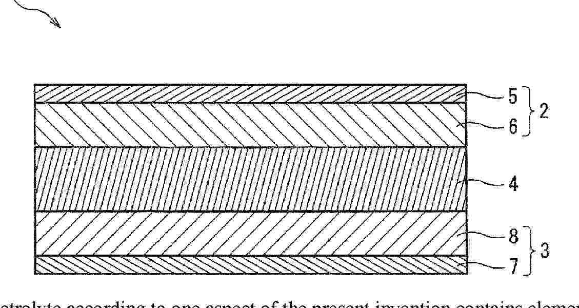
A solid electrolyte according to one aspect of the present invention contains a lithium element, a phosphorus element, a silicon element, a sulfur element, and a halogen element, in which the molar ratio (Si/(P+Si)) of the content of the silicon element to the total content of the phosphorus element and the silicon element is 0.04-0.55 inclusive, the molar ratio (S/(P+Si)) of the content of the sulfur element to the total content of the phosphorus element and the silicon element is 3.50-4.10 inclusive, the halogen element contains at least one of a bromine element and an iodine element, and the molar ratio ((Br+I)/X) of the total content of the bromine element and the iodine element to the content of the halogen element is 0.80 or more, and the solid electrolyte has a predetermined crystal structure.
 BOPI
BOPI
 Sede Electrónica