Si deseas distinguir tus productos, servicios o ambos de los de otra empresa, es posible que necesites una marca o nombre comercial. Descubre qué son, en qué consiste su procedimiento de registro y qué implica.

Información sobre los plazos de presentación de solicitudes de transformación de marcas de la Unión Europea en marca nacional española. Más información


Si tienes un nuevo dispositivo, producto o procedimiento que resuelva un problema técnico o tenga una ventaja práctica, existen distintas formas de protegerlo en España y en otros países. Descubre cómo hacerlo.

¿Tu innovación reside en la estética, la ornamentación o la apariencia de tu producto? Protégela mediante un diseño industrial. Descubre qué derechos confiere el registro y cómo realizar la tramitación.

Las indicaciones geográficas protegen el nombre de un producto originario de una zona geográfica, a la cual le debe una determinada calidad, reputación u otra característica. Descubre qué son, en qué consiste su procedimiento de registro y qué beneficios conceden.

Las patentes publicadas en todo el mundo son una valiosa fuente de información científica, técnica y comercial.

Si eres emprendedor/a o una empresa y quieres potenciar y mejorar la rentabilidad de tu negocio protegiendo de forma adecuada los activos intangibles de tu organización, en este espacio encontrarás lo necesario.


 1653
resultados
1653
resultados
 Última actualización
13/03/2026 [07:13:00]
Última actualización
13/03/2026 [07:13:00]


 Resultados 50 a 75 de 1653

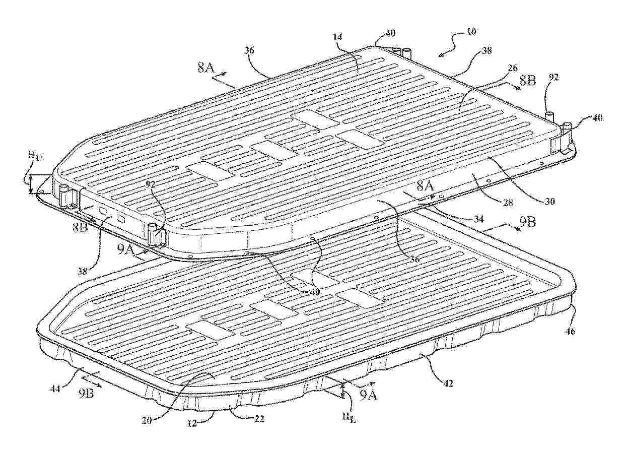
Resumen de: CN121014138A
A battery housing for an automobile includes a lower basin and an upper cover disposed on the lower basin to collectively define an interior cavity. At least one battery module is disposed in the interior cavity and encapsulated between the lower basin and the upper cover. At least one of the lower basin or the upper cover is formed as a one-piece stamped part by a two-part expansion forming process. In a preferred arrangement, both the lower basin and the upper cover of the battery case are each formed as a one-piece stamped part by a two-part expansion forming process, which provides both the upper cover and the lower basin, which are more compact than the one-piece stamped part design of the prior art. The upper cover and the lower basin have a tighter draft angle (less than 2 degrees) and sharper upper and lower corners (a plan corner radius between 20 mm and 95 mm, etc.), increasing the space for the interior cavity.

Resumen de: WO2024226833A1
A lithium-ion battery cell includes an electrode assembly having an anode and a cathode. The anode includes an anode current collector and a first silicon-containing anode active material layer disposed on a first side of the anode current collector, where the first silicon-containing anode active material layer includes at least 85 atomic % silicon. The cathode includes a cathode current collector and a first cathode active material layer disposed on a first side of the cathode current collector, where the first side of the cathode current collector is proximal to the first side of the anode current collector. The battery cell further includes a lithium-ion electrolyte disposed between the anode and cathode, and a battery cell housing containing the electrode assembly and the electrolyte. During an electrochemical charging event, the first cathode active material layer is compressible to less than 95% of its thickness prior to the charging event.
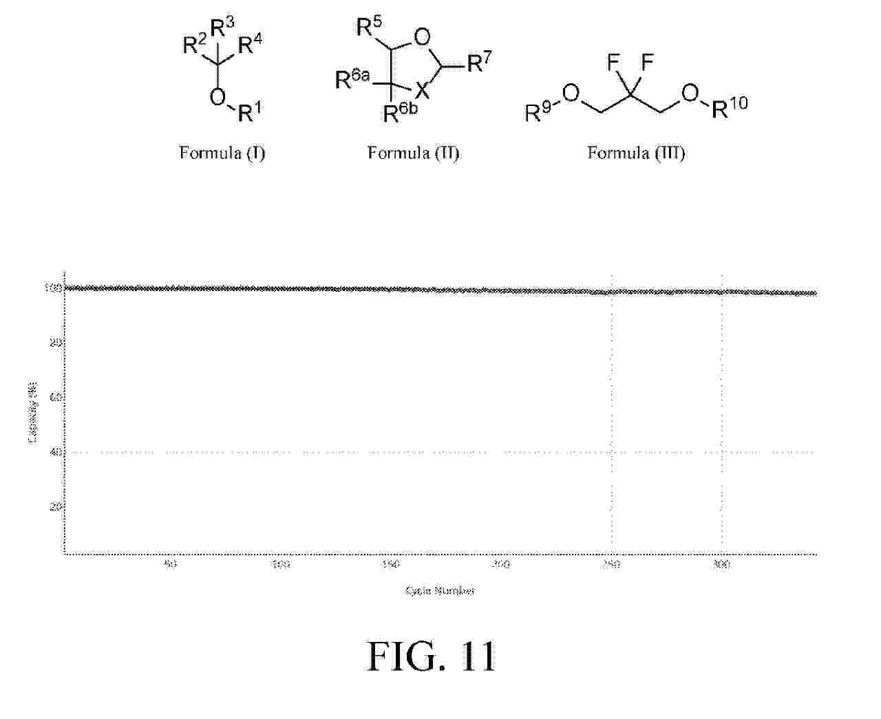
Resumen de: WO2024226580A2
Provided herein are halogenated ether compounds of Formula (I), Formula (II), or Formula (III): Formula (I)Formula (II)Formula (III) Also provided are electrolytes comprising one or more compounds of Formula (I), Formula (II), or Formula (III) and electrochemical cells comprising electrolytes comprising one or more compounds of Formula (I), Formula (II), or Formula (III).
Resumen de: CN119731791A
A coating is disclosed comprising two elements (A and B) and a carbonaceous material, where element A is capable of alloying with lithium and element B is not capable of alloying with lithium. A method for preparing the coating and an all solid state battery (ASSB) comprising the coating are also disclosed. In one embodiment, ASSBs comprising the coating exhibit reduced charge overpotential as well as improved specific capacity and cycle life.
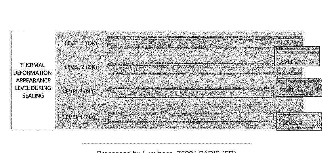
Resumen de: EP4708477A1
The present specification relates to a cell pouch film, a packaging structure comprising same, and a method for storing the corresponding cell pouch film. Therefore, the moisture regain of the cell pouch film is controlled such that moldability, the level of thermal deformation bubbles, and mechanical properties can all be excellent.
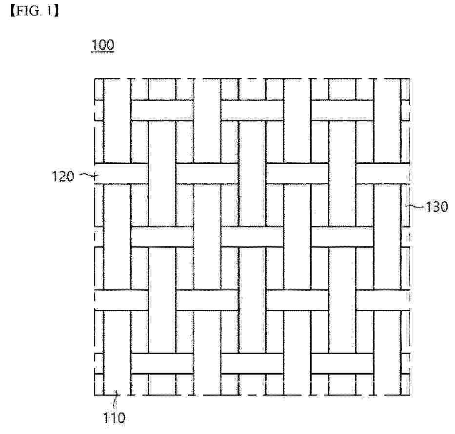
Resumen de: EP4707459A1
A molded article of the present invention comprises: a woven composite sheet formed from two or more stacked sheets of thermoplastic continuous fiber reinforced woven composites; and a nonwoven fabric heated and compressed to be stacked on at least one surface of the woven composite sheet, wherein the thermoplastic continuous fiber reinforced woven composites are woven using, as warp and weft, a glass fiber composite comprising approximately 100 parts by weight of glass fiber, approximately 35-72 parts by weight of a polypropylene resin, approximately 12-35 parts by weight of piperazine pyrophosphate, approximately 1-20 parts by weight of a phosphazene compound and approximately 1-20 parts by weight of zeolite. The glass fiber composite has excellent lightweightness, flame retardancy, impact resistance, stiffness, exterior characteristics and the like.
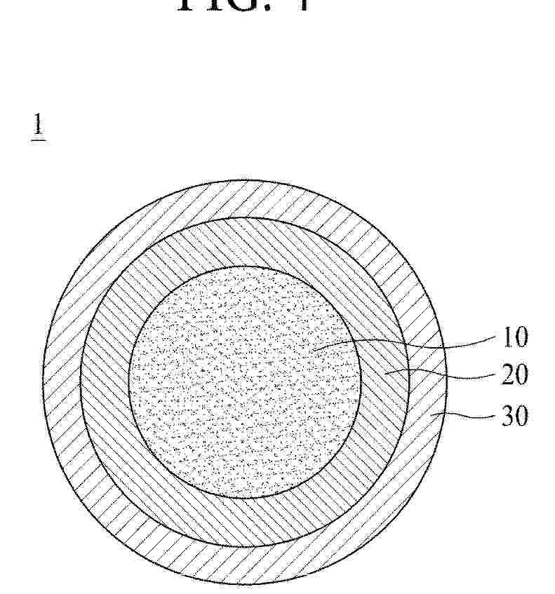
Resumen de: EP4706787A1
A fire extinguishing material for lithium battery fire suppression, of the present invention, is composed of: a granular first fire extinguishing material, which is prepared by firing a silica powder and the like and which has a predetermined size; a second fire extinguishing material of a single-layer graphene compound applied, in multiple layers, to the surface of the first fire extinguishing material; and a third fire extinguishing material made of a metal carbonate covalently bonded or applied to the graphene compound. During a lithium battery fire, when the fire extinguishing material of the present invention is applied to a fire source through a discharge means such as a fire extinguisher, the fire extinguishing material is put on top of the fire source, the second fire extinguishing material, that is, the metal carbonate, which comes in direct contact with the fire source, adsorbs carbon dioxide, which is most abundantly generated from the fire source, so as to absorb radicals while being converted into a bicarbonate, thereby primarily extinguishing the fire, and the graphene compound, which is the second fire extinguishing material with excellent thermal conductivity, rapidly releases heat from the fire to the outside so as to improve, by means of effective cooling, fire extinguishing performance for the lithium battery fire, thereby preventing thermal runaway during the lithium battery fire, and extinguishes the lithium battery fire together with an additional smothe
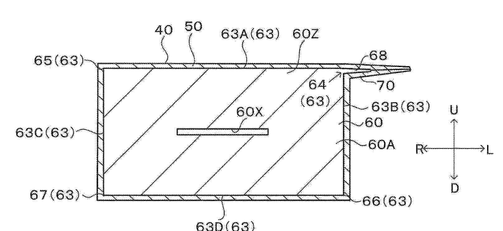
Resumen de: EP4708485A1
Provided is a lid used with a casing of a power storage device, wherein the lid includes a heat-fusible resin layer the main material of which is an olefin-based copolymer.
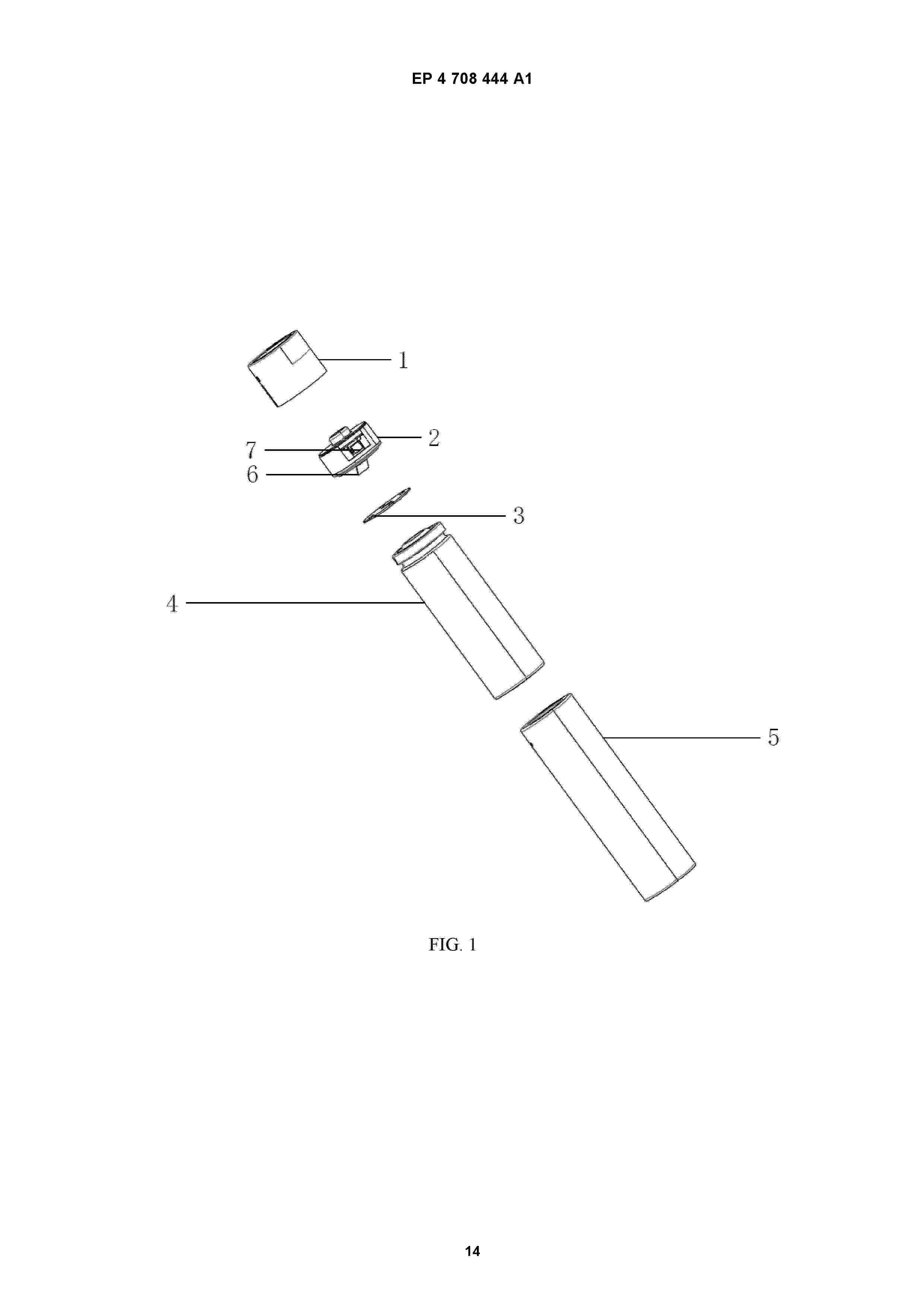
Resumen de: EP4708444A1
The present application relates to a preparation method, apparatus, device and medium for a No. 5 lithium-ion battery. The method includes: preparing a battery cell based on a preparation process of the battery cell; selecting a steel material for preparing the battery and stamping it to obtain an upper steel shell of the battery; acquiring and determining bending parameters of the spring sheet based on user requirements and attribute parameters of the spring sheet; assembling a PCB board and the upper steel shell of the battery based on the bending parameters of the spring sheet, bending a negative spring sheet on a side of the PCB board downwards, so that the negative spring sheet is in elastic contact with the upper steel shell, and bending a positive spring sheet at a bottom of the PCB board downwards, so that the positive spring plate is in elastic contact with a top of the battery cell, thus obtaining a complete step-down charging terminal; fitting the complete step-down charging terminal onto the battery cell to obtain a semi-finished product of the battery; and fixing the semi-finished product of the battery by roller pressing along a groove of the battery cell, and covering an insulating film on a outside of the semi-finished product after being fixed roller pressing to obtain a finished product of the battery. The present application has an effect of improving a safety of lithium-ion batteries.
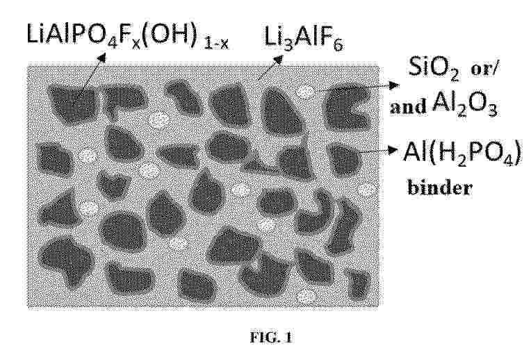
Resumen de: EP4707258A1
Provided in the present disclosure is a composite material, which comprises LiAlPO4(OH)xF1-x and Al(H2PO4)3 compounded on the surface of the LiAlPO4(OH)xF1-x, wherein 0≤x≤1. A corresponding core-shell/glassy solid-state electrolyte material is also prepared in the present disclosure. The composite solid electrolyte has good ionic conductivity, good flexibility, a stable composite structure and thermal stability, such that when being applied to positive electrode coating, the composite solid electrolyte can slow down reduction in the capacity of a positive electrode by a coating layer, effectively remove alkaline residual lithium left on the surface in the preparation process of a positive electrode material, and convert the residual lithium into Li3PO4 favorable for ionic conductivity of the coating layer and AlPO4 capable of protecting the positive electrode. Moreover, Li3AlF6 is more stable to HF, and the good flexibility of a glassy structure thereof is beneficial to effective interfacial contact between the positive electrode and an electrolyte solution of the electrolyte, such that good interfacial ion conduction is achieved.
Resumen de: EP4707242A1
The present disclosure provides a lithium ion battery material and a preparation method therefor and a use thereof. The structural formula of the lithium ion battery material is Li4ZrF8-2XOX, wherein 0
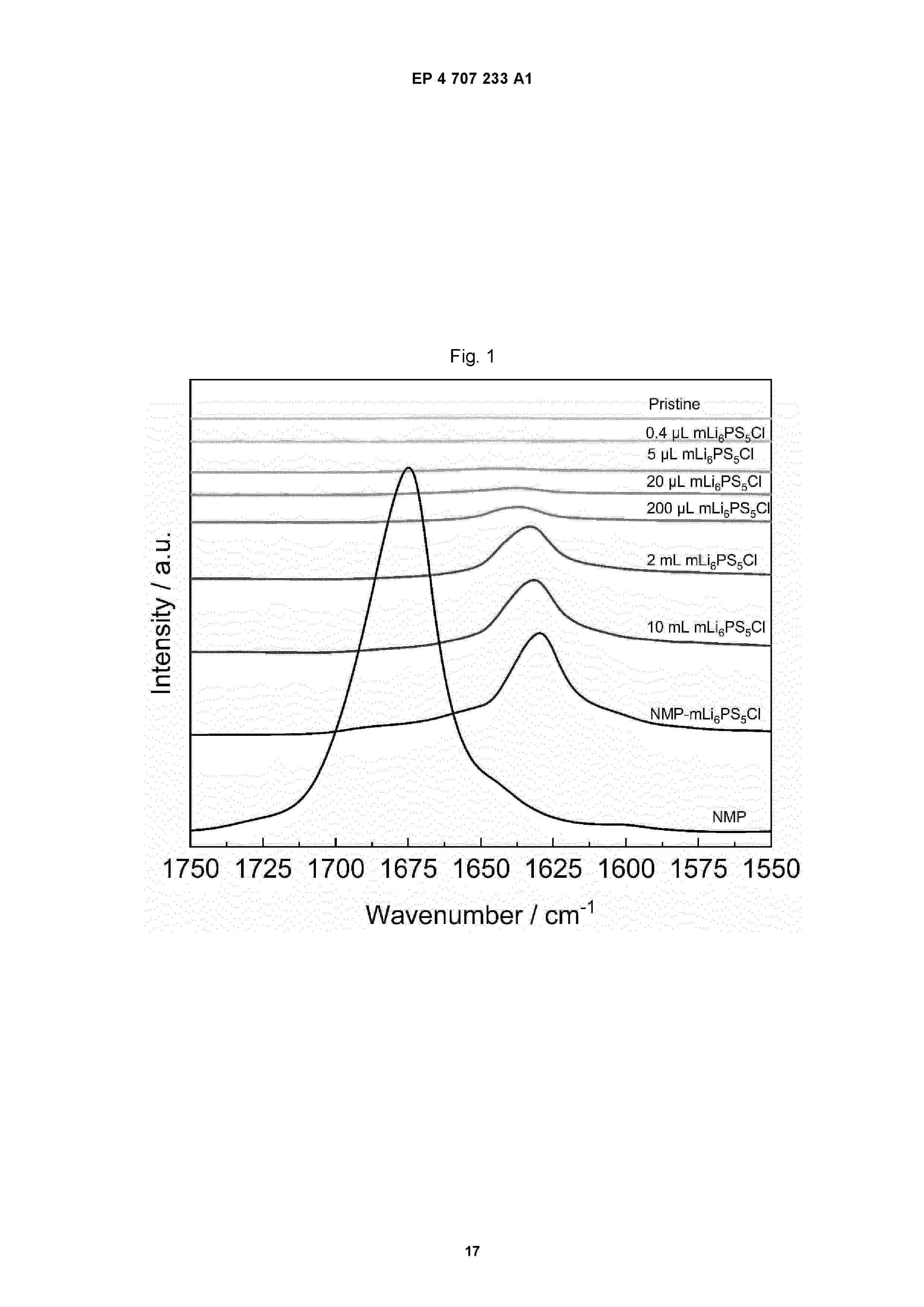
Resumen de: EP4707233A1
The subject matter of the invention provides a viable solvent treatment method for manufacturing surface-modified alkali metal sulfides or alkali metal thiophosphates, especially surface-modified lithium thiophosphates, e.g. Li<sub>6</sub>PS<sub>5</sub>Cl (mLi<sub>6</sub>PS<sub>5</sub>Cl). Utilizing nonpolar organic solvents to reduce the concentration of additives with Lewis-basic activity, the surface of, for example Li<sub>6</sub>PS<sub>5</sub>Cl, is modified to improve the ionic conductivity of electrolytes of type Li<sub>6</sub>PS<sub>5</sub>Cl or other lithium thiophosphates.
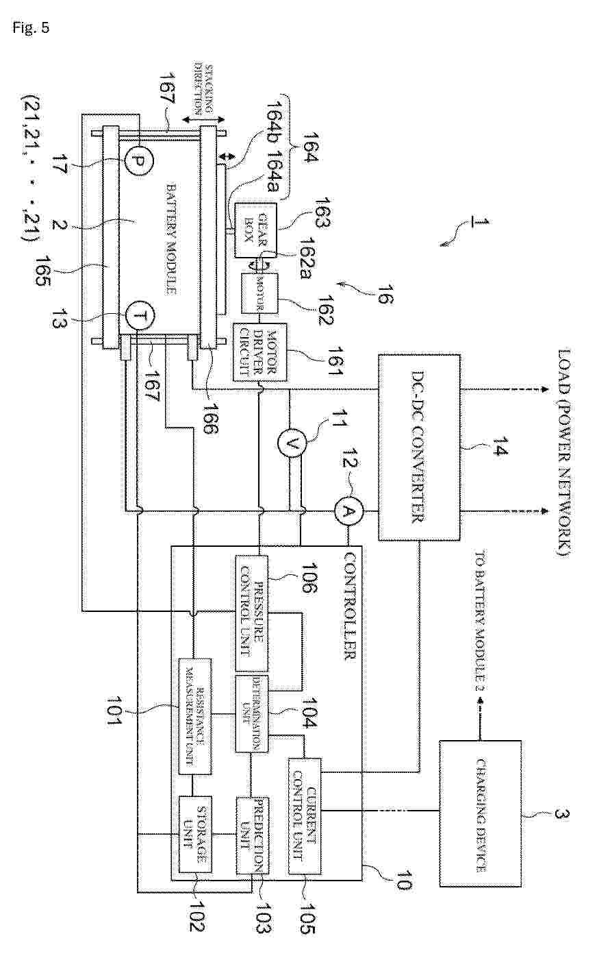
Resumen de: EP4708611A1
A short circuit precursor detection system (1) includes a battery cell (21), a temperature sensor (13) that measures a battery temperature, a resistance measurement unit (101) that measures electrolyte resistance of a solid-state electrolyte of the battery cell (21), and a determination unit (104) that determines presence or absence of a precursor of occurrence of short circuit between a positive electrode and a negative electrode. The determination unit (104) determines that the precursor is present when an amount of decrease of the electrolyte resistance measured by the resistance measurement unit (101) during charging is larger than an amount of decrease of the electrolyte resistance caused by change in the battery temperature by a predetermined value or more.
Resumen de: EP4707416A1
The invention relates to a battery foil (current collector) comprising an aluminum alloy, with the following composition:Si: 0.1 - 0.2wt-%,Fe: ≤ 0.6wt-%,Cu: 0.1 - 0.2wt-%,Mn: 0.03 - 0.05wt-%,Mg: 0.0 - 0.05wt-%Zn: 0.0-0.1wt-%Ti: 0.0 - 0.05wt-%,with 3-4 times as much Fe as Si,with at least 4 times as much Cu as Ti,wherein the aluminum alloy may have impurities of Cd with a max 20ppm, Pb with a max 100ppm and Hg with a max 5ppm, the sum of Pb, Hg, Cd and CrVI being ≤100ppm, the others (not mentioned) individually <0.05 wt-% and the sum of the others ≤0.15 wt-%, with the rest of the alloy being Al,and, wherein the battery cathode foil has intermetallic phases having an average diameter length of 0.5µm or more and their number density being on average 1.3×10<4>particles/mm<2> or more.
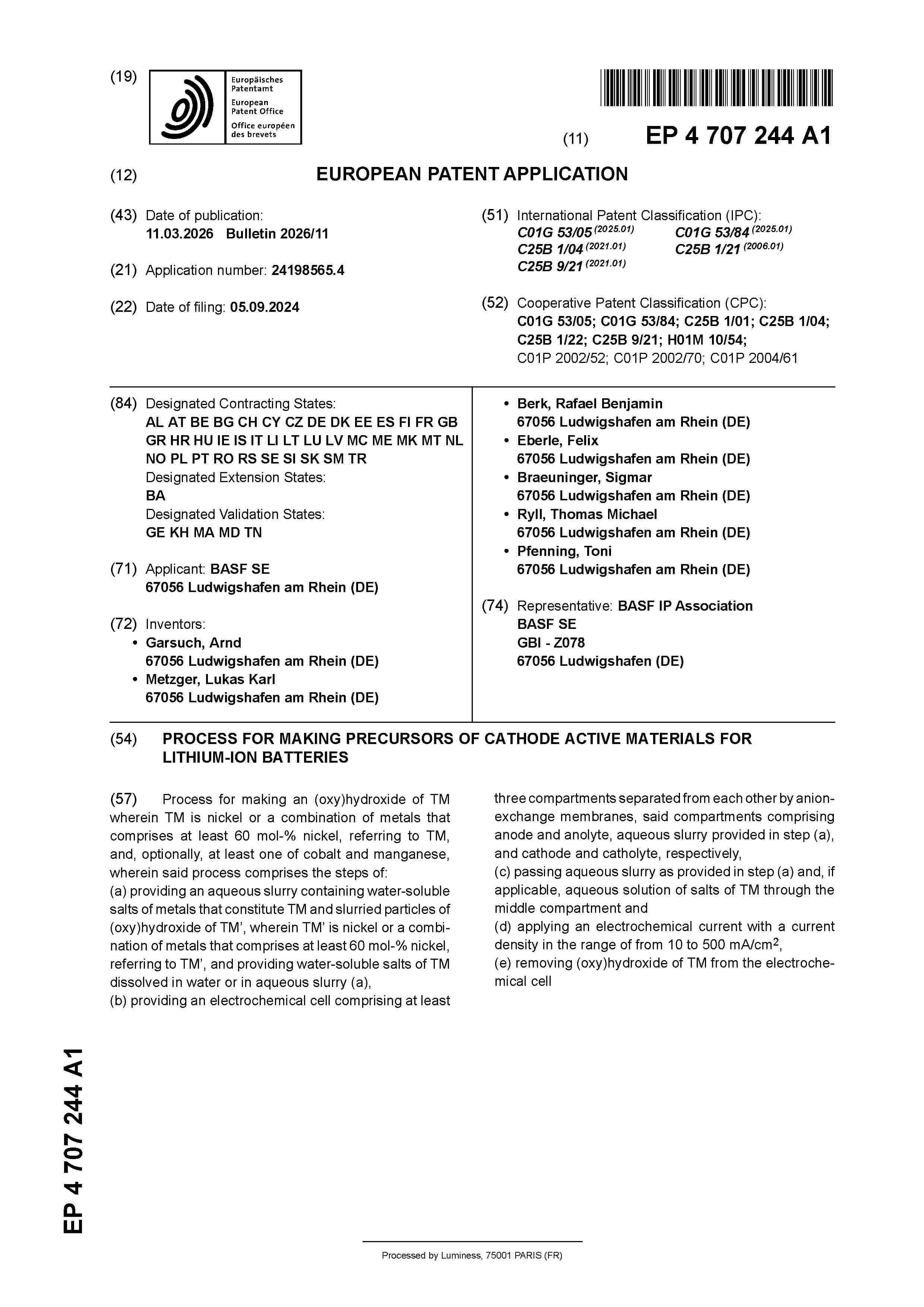
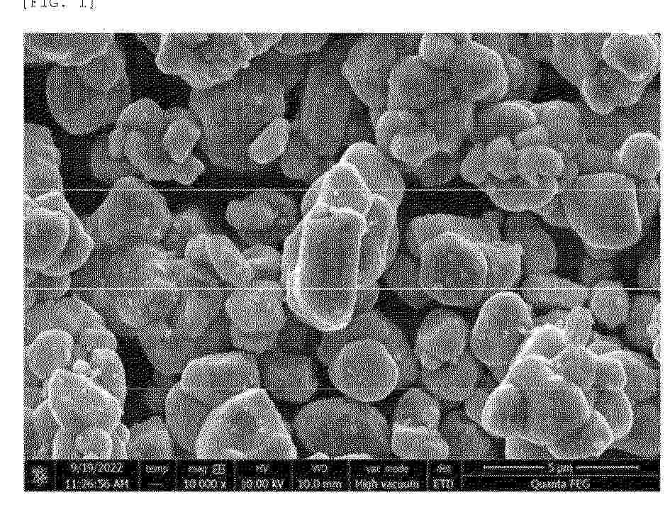
Resumen de: EP4707244A1
Process for making an (oxy)hydroxide of TM wherein TM is nickel or a combination of metals that comprises at least 60 mol-% nickel, referring to TM, and, optionally, at least one of cobalt and manganese, wherein said process comprises the steps of:(a) providing an aqueous slurry containing water-soluble salts of metals that constitute TM and slurried particles of (oxy)hydroxide of TM', wherein TM' is nickel or a combination of metals that comprises at least 60 mol-% nickel, referring to TM', and providing water-soluble salts of TM dissolved in water or in aqueous slurry (a),(b) providing an electrochemical cell comprising at least three compartments separated from each other by anion-exchange membranes, said compartments comprising anode and anolyte, aqueous slurry provided in step (a), and cathode and catholyte, respectively,(c) passing aqueous slurry as provided in step (a) and, if applicable, aqueous solution of salts of TM through the middle compartment and(d) applying an electrochemical current with a current density in the range of from 10 to 500 mA/cm<sup>2</sup>,(e) removing (oxy)hydroxide of TM from the electrochemical cell
Resumen de: EP4708388A1
The present invention relates to a positive electrode active material capable of improving performance of a lithium secondary battery, wherein it relates to a positive electrode active material including a lithium composite transition metal oxide in a form of a single particle; and a coating portion which is formed on the lithium composite transition metal oxide and includes an amorphous lithium compound, wherein the coating portion includes a first coating portion; and a second coating portion, wherein the first coating portion is in a form of a discontinuously formed island, and the second coating portion is in a form of a continuously formed coating layer, wherein the first coating portion and the second coating portion each independently include boron (B) and cobalt (Co), and optionally include at least one coating element selected from the group consisting of Co, Al, Ba, Ce, Cr, F, Mg, V, Ti, Fe, Zr, Zn, Si, Y, Nb, Ga, Sn, Mo, W, P, S, Sr, Ta, La, and Hf, and a positive electrode and a lithium secondary battery which include the same.
Resumen de: EP4708398A1
The present invention relates to a positive electrode active material comprising a lithium transition metal oxide in a form of a single particle, wherein the lithium transition metal oxide contains 60 mol% or more of nickel among total transition metals, wherein, when a pressure of 6,500 kgf/cm<sup>2</sup> is applied to the positive electrode active material, an amount of fine powder having a particle diameter of 1 µm or less is 10 vol% or less based on a total volume of the positive electrode active material after the applying the pressure, a method for preparing the positive electrode active material, and a positive electrode and lithium secondary battery including the positive electrode active material.
Resumen de: EP4708387A1
The present invention relates to a positive electrode active material including a lithium composite transition metal oxide in a form of a single particle; and a coating portion formed on a surface of the lithium composite transition metal oxide, wherein the coating portion includes a first coating portion; and a second coating portion, wherein the first coating portion is in a form of a discontinuously formed island, and the second coating portion is in a form of a continuously formed coating layer, wherein the first coating portion has a concentration gradient in which an amount of boron (B) decreases and an amount of cobalt (Co) increases from a surface thereof toward a center of a positive electrode active material particle, and the amount of the boron (B) among total metals excluding lithium in the positive electrode active material is in a range of 0.1 mol% to 1.25 mol%, and a positive electrode and a lithium secondary battery which include the same.
Resumen de: WO2025022197A1
Castable compositions are described. The castable composition comprise a liquid silicone rubber, a thixotropic agent comprising organic fibrils, and hollow glass microspheres. Cured compositions and methods of making the castable compositions, as well as battery modules comprising a plurality of battery cells and such cured compositions are also described.
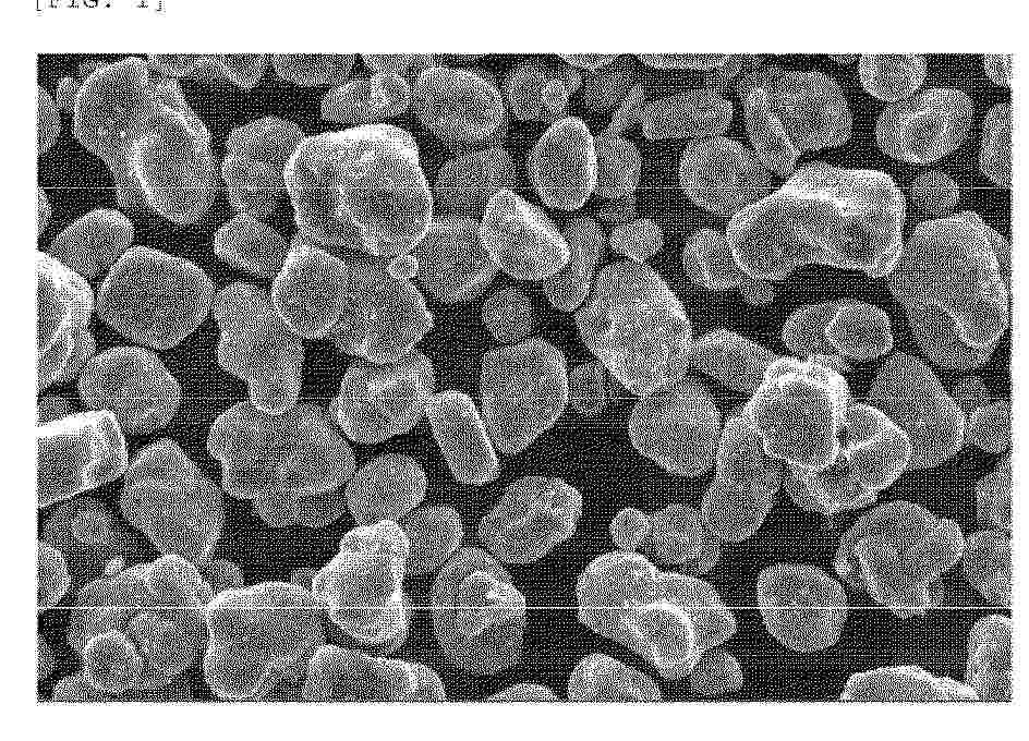
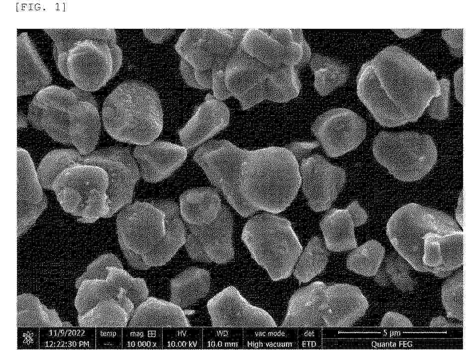
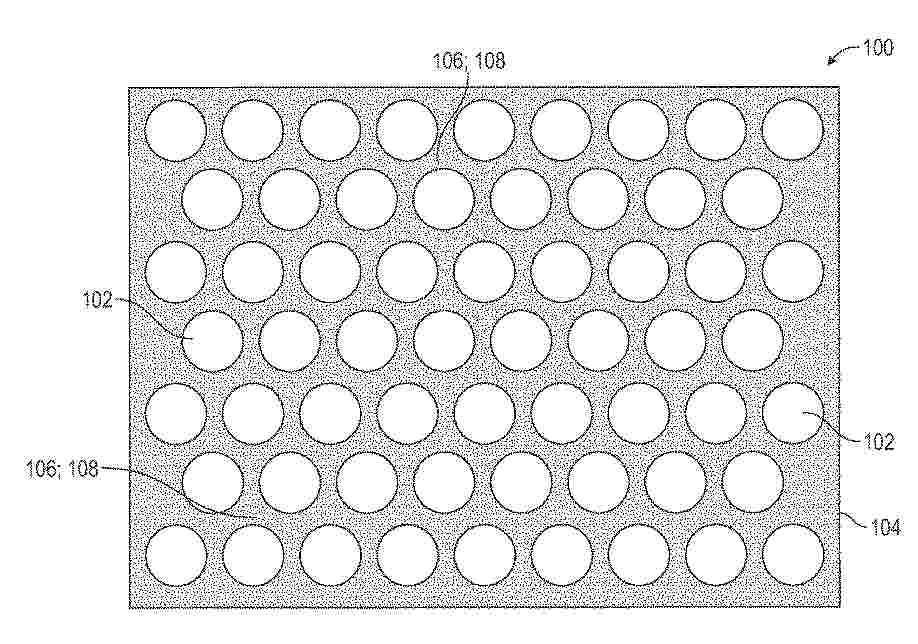
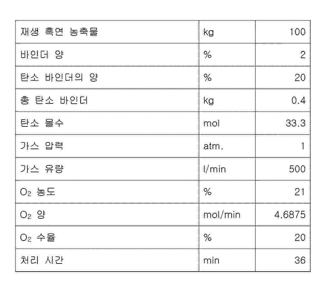
Resumen de: AU2024265063A1
The present disclosure concerns a method (100) for producing recycled graphite, the method (100) comprising the steps of providing a reclaimed graphite concentrate comprising any one or more of carboxymethyl cellulose and styrene-butadiene rubber, pre-treating (120) the reclaimed graphite concentrate by subjecting the reclaimed graphite concentrate to an oxidizing environment at a temperature in the range 250 - 380 °C, thereby reducing the total concentration of carboxymethyl cellulose and styrene- butadiene rubber to less than 0.25 %, and thermally treating (130) the pre-treated reclaimed graphite concentrate by subjecting the pre-treated reclaimed graphite concentrate to a non-oxidizing environment at a temperature of at least 2300 °C. The invention also describes a recycled graphite, use of a recycled graphite, and a battery comprising a recycled graphite.
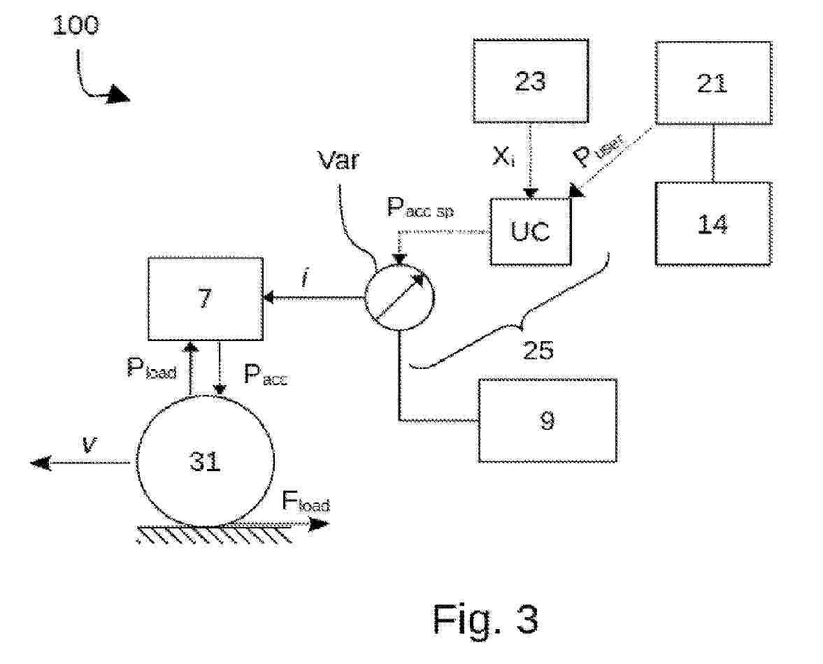
Resumen de: WO2024227995A1
The invention relates to a device for controlling an electric motor (7) of a vehicle (1), comprising: a pedal assembly (14); means (23) for estimating state variables (Xi) each making it possible to estimate the value of one force from a set of forces (Fload) opposing or contributing to the progress of the vehicle (1); wherein the control means (25) comprise a memory storing a set of steady states (SSmap) of the pedal assembly (14) defining the instantaneous power (Pssp user) for keeping the speed (v) of the vehicle (1) constant according to the values of the state variables (Xi); the control means (25) being configured to accelerate or decelerate the vehicle (1) if the power applied by the user (Puser) is higher or lower, respectively, than the instantaneous power for keeping the speed of the vehicle constant (Pssp user).
Resumen de: EP4708386A1
The present invention relates to a positive electrode active material capable of improving performance of a lithium secondary battery, the positive electrode active material including a lithium composite transition metal oxide in a form of a single particle; and a coating portion provided on the lithium composite transition metal oxide, wherein the coating portion comprises a first coating portion and a second coating portion, wherein the first coating portion is in a form of a discontinuously formed island, and the second coating portion is in a form of a continuously formed coating layer, wherein the first coating portion comprises boron (B) and optionally comprises at least one coating element selected from the group consisting of Co, Al, Ba, Ce, Cr, F, Mg, V, Ti, Fe, Zr, Zn, Si, Y, Nb, Ga, Sn, Mo, W, P, S, Sr, Ta, La, and Hf, the second coating portion comprises a compound having a composition represented by Formula 1 or 2 set forth in the specification, and an amount of boron (B) among total metals excluding lithium in the positive electrode active material is 0.1 mol% to 1.25 mol%, a method for preparing the positive electrode active material, and a positive electrode and lithium secondary battery including the positive electrode active material.
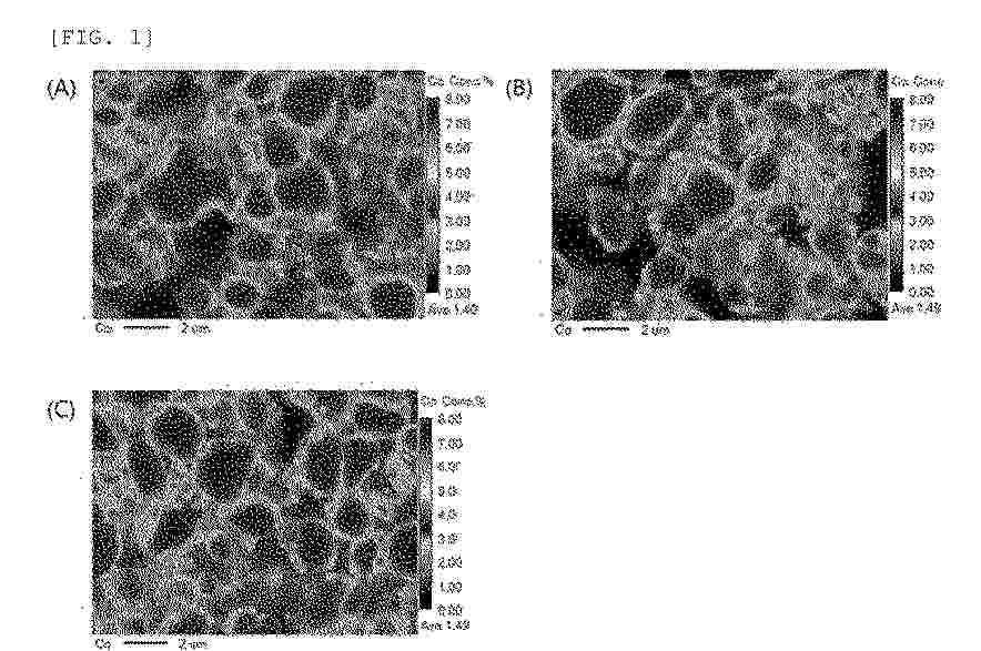
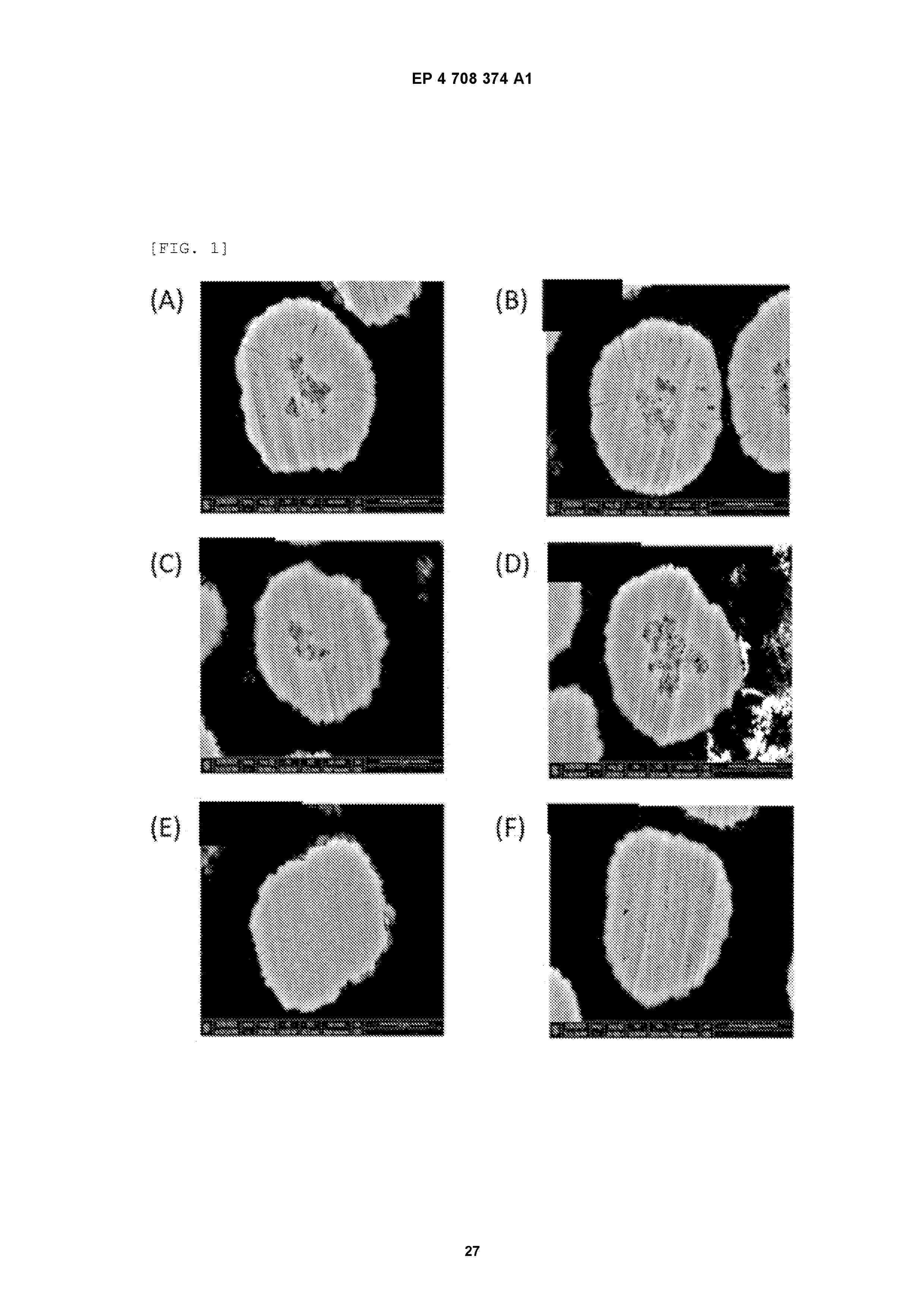
Resumen de: EP4708374A1
The present invention relates to a positive electrode active material capable of improving performance of a lithium secondary battery, the positive electrode active material including: a first lithium composite transition metal oxide in a form of a single particle; and optionally a second lithium composite transition metal oxide in a form of a single particle, wherein the first lithium composite transition metal oxide in the form of a single particle includes 30 or less disk-type primary particles, wherein each of the disk-type primary particles is a primary particle observed from a scanning electron microscope (SEM) image of a surface or cross section of the positive electrode active material, wherein, when an imaginary tangent line with the most contact points is drawn to each of two boundary lines of the primary particle present within an angle of 45° or less based on a long diameter direction and one imaginary line crossing the two tangent lines is drawn, interior angles of same side are at least 150° and at most 210°, and an aspect ratio of (major axis/minor axis) is 1.5 or more, wherein the positive electrode active material includes the first lithium composite transition metal oxide in an amount of 20 vol% to 100 vol% based on a total volume of the positive electrode active material, a method for preparing the positive electrode active material, and a positive electrode and lithium secondary battery including the positive electrode active material.
Resumen de: EP4708384A1
The present invention relates to a method of preparing a positive electrode slurry composition, which includes steps of (S1) adding a positive electrode active material, a conductive agent, a binder, and a non-aqueous solvent to a mixer and mixing to prepare a mixture having a solid content of greater than 60 wt% and a temperature of -20°C to 45°C; (S2) cooling the mixture to -30°C to 15°C to prepare a positive electrode slurry composition precursor; and (S3) maintaining a temperature of the positive electrode slurry composition precursor to prepare a positive electrode slurry composition having a V<sub>72</sub> of 0% to 50%, wherein V<sub>n</sub> is a viscosity increase rate when the temperature of the positive electrode slurry composition precursor is maintained for n hours, and the viscosity increase rate is represented by Equation 1 described in the present specification, and a method of preparing a positive electrode.
Nº publicación: EP4706112A1 11/03/2026
Solicitante:
COATEX SAS [FR]
Coatex
Resumen de: CN121039820A
The present invention relates to a composition for preparing a positive electrode undercoat layer comprising a polyacrylic acid binder having a low molecular weight and carbon particles. The invention also relates to the use of said composition for producing a positive electrode and to a positive electrode which can be used for producing a rechargeable battery cell.
 BOPI
BOPI
 Sede Electrónica