Si deseas distinguir tus productos, servicios o ambos de los de otra empresa, es posible que necesites una marca o nombre comercial. Descubre qué son, en qué consiste su procedimiento de registro y qué implica.

Información sobre los plazos de presentación de solicitudes de transformación de marcas de la Unión Europea en marca nacional española. Más información


Si tienes un nuevo dispositivo, producto o procedimiento que resuelva un problema técnico o tenga una ventaja práctica, existen distintas formas de protegerlo en España y en otros países. Descubre cómo hacerlo.

¿Tu innovación reside en la estética, la ornamentación o la apariencia de tu producto? Protégela mediante un diseño industrial. Descubre qué derechos confiere el registro y cómo realizar la tramitación.

Las indicaciones geográficas protegen el nombre de un producto originario de una zona geográfica, a la cual le debe una determinada calidad, reputación u otra característica. Descubre qué son, en qué consiste su procedimiento de registro y qué beneficios conceden.

Las patentes publicadas en todo el mundo son una valiosa fuente de información científica, técnica y comercial.

Si eres emprendedor/a o una empresa y quieres potenciar y mejorar la rentabilidad de tu negocio protegiendo de forma adecuada los activos intangibles de tu organización, en este espacio encontrarás lo necesario.


 1509
resultados
1509
resultados
 Última actualización
17/03/2026 [07:16:00]
Última actualización
17/03/2026 [07:16:00]


 Resultados 750 a 775 de 1509

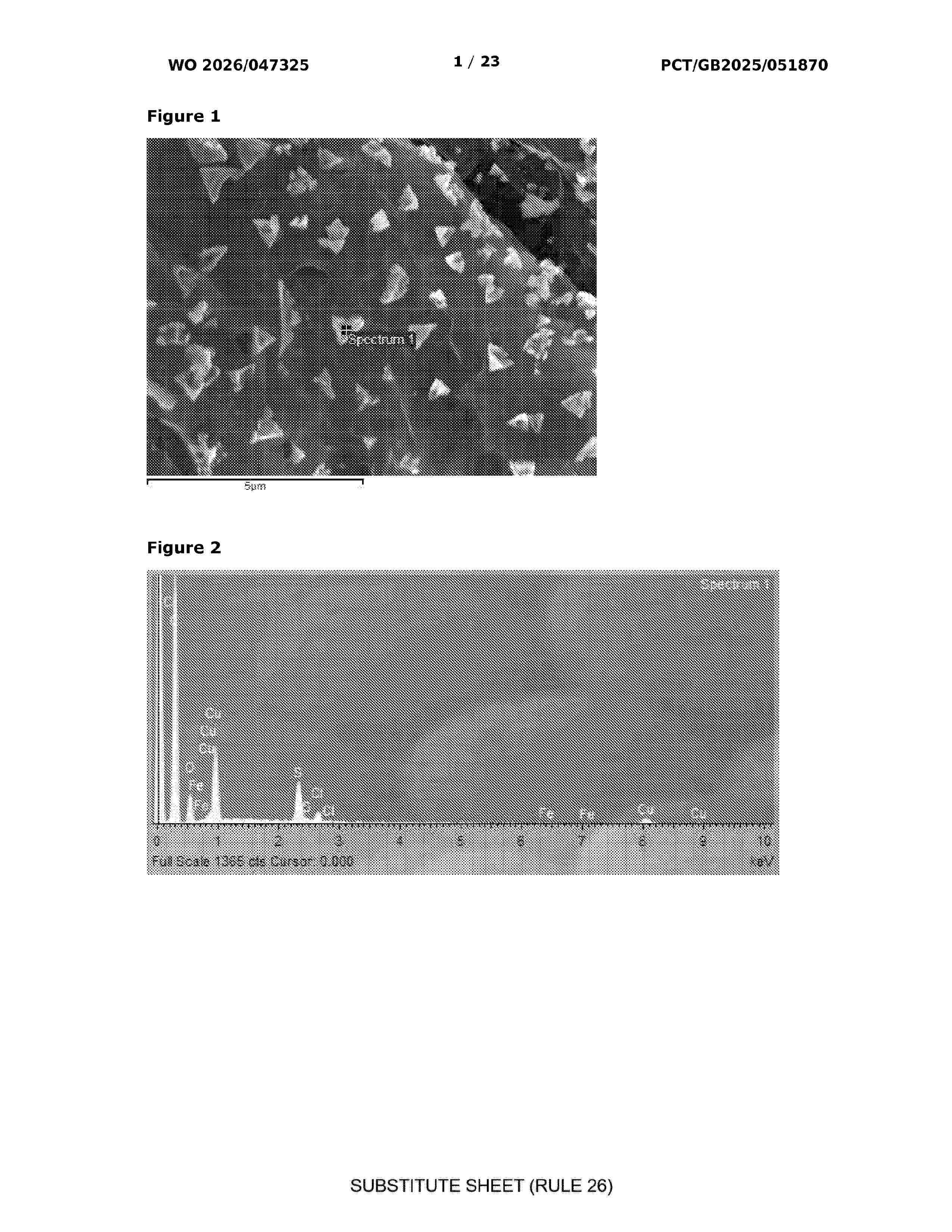
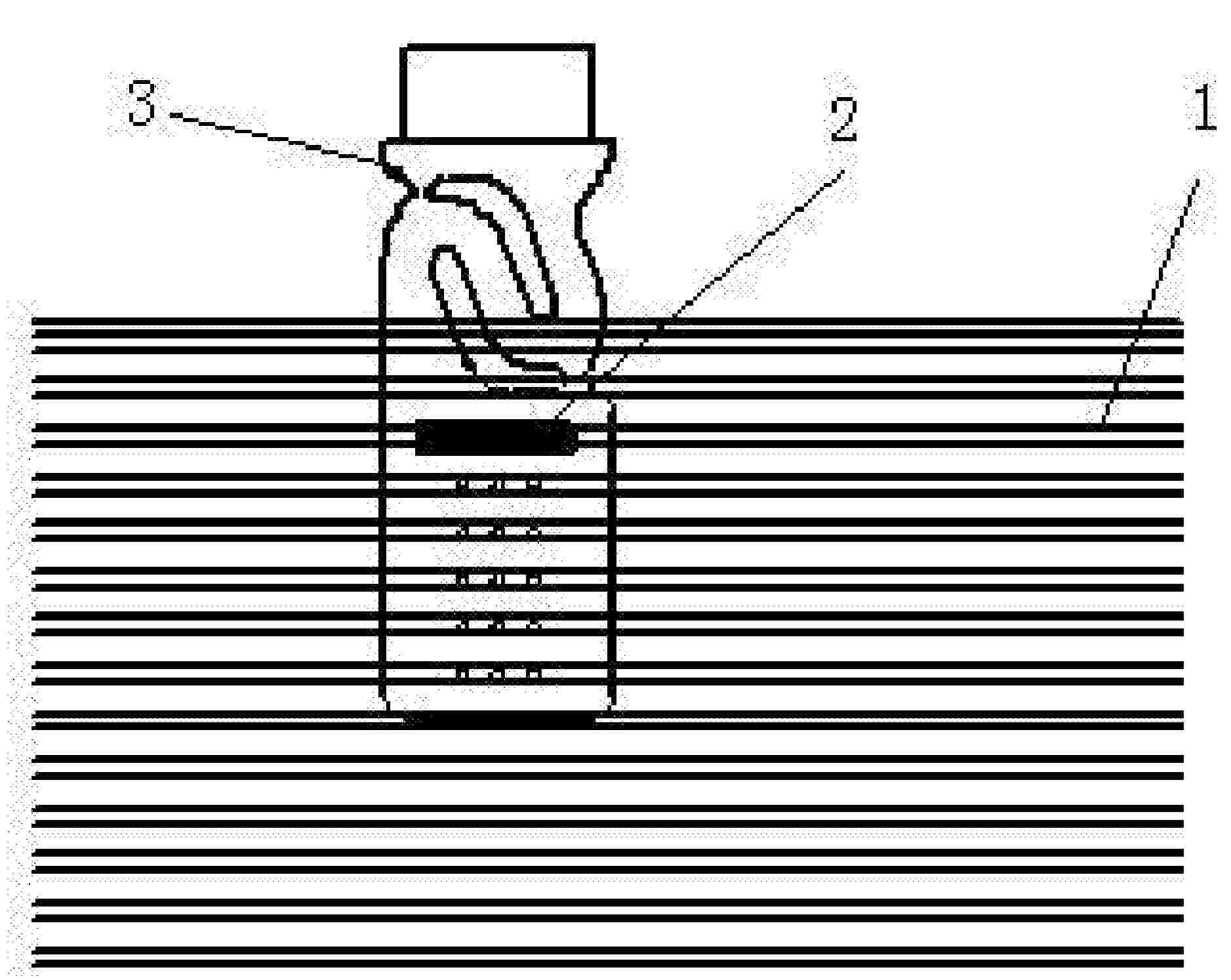
Resumen de: WO2026047325A1
The disclosure relates to a method of recovering a target metal, a compound comprising the target metal or a salt thereof, from a composition comprising the target metal or a first oxidised form thereof. The method comprises contacting the composition and an extraction liquid to extract the target metal or the first oxidised form thereof from the composition and to thereby produce a first solution. The extraction liquid comprises or consists of an ionic liquid and/or a deep eutectic solvent (DES) and the first solution comprises a second oxidised form of the target metal dissolved therein. The method further comprises conducting a reaction to cause the second oxidised form of the target metal to be converted to the target metal, the compound comprising the target metal or a solid salt of the target metal.

Resumen de: US20260068049A1
Disclosed are a flexible printed circuit and a battery pack. The flexible printed circuit comprises a flexible cable, wherein a window portion is formed in the middle of the flexible cable, and a flexible die-cutting circuit is electrically connected to the window portion. The flexible cable is a flexible flat cable. The flexible die-cutting circuit or a small flexible printed circuit is electrically connected to the window portion. The window portion is rectangular. The invention has the beneficial effect that an FCC manufactured by a new process is bendable while original FFCs and FDCs are non-bendable.
Resumen de: US20260066337A1
A separator for a sodium battery, and a sodium battery, a secondary battery, and an electric apparatus comprising the separator. The separator for the sodium battery has a first surface and a second surface along its thickness direction, and a porosity of the separator decreases gradually from the first surface to the second surface.
Resumen de: US20260066348A1
A non-aqueous electrolyte includes vinylene carbonate and Formula I compound, where based on a total mass of the non-aqueous electrolyte, a mass percentage of vinylene carbonate is A %, where 0.01≤A≤3; a mass percentage of a compound of Formula I is B %; and P=B/A, where 0.5≤P≤50.
Resumen de: US20260066375A1
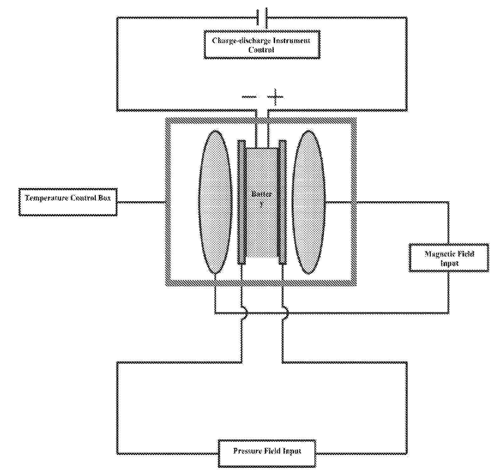
A multi-field synergistic repair method for retired batteries and devices thereof relates to the technical field of battery repair, which comprises the following steps: charging and discharging a retired battery in sequence; the charging and/or discharging are performed under the action of synergistic fields to obtain a regenerated battery; the synergistic fields are at least one of magnetic fields, pressure fields or temperature fields; the charging and discharging are cycled 1 time to 20 times in total. The invention solves the problems of complex process, high cost and poor effect of existing battery recycling processes; the battery performance can be restored to more than 80% of the initial capacity of the new battery, realizing the regeneration of lithium-ion batteries and sodium-ion batteries; the battery regeneration method has the advantages of no need to disassemble the battery, short time, low energy consumption, low cost, and zero emission.
Resumen de: US20260066353A1
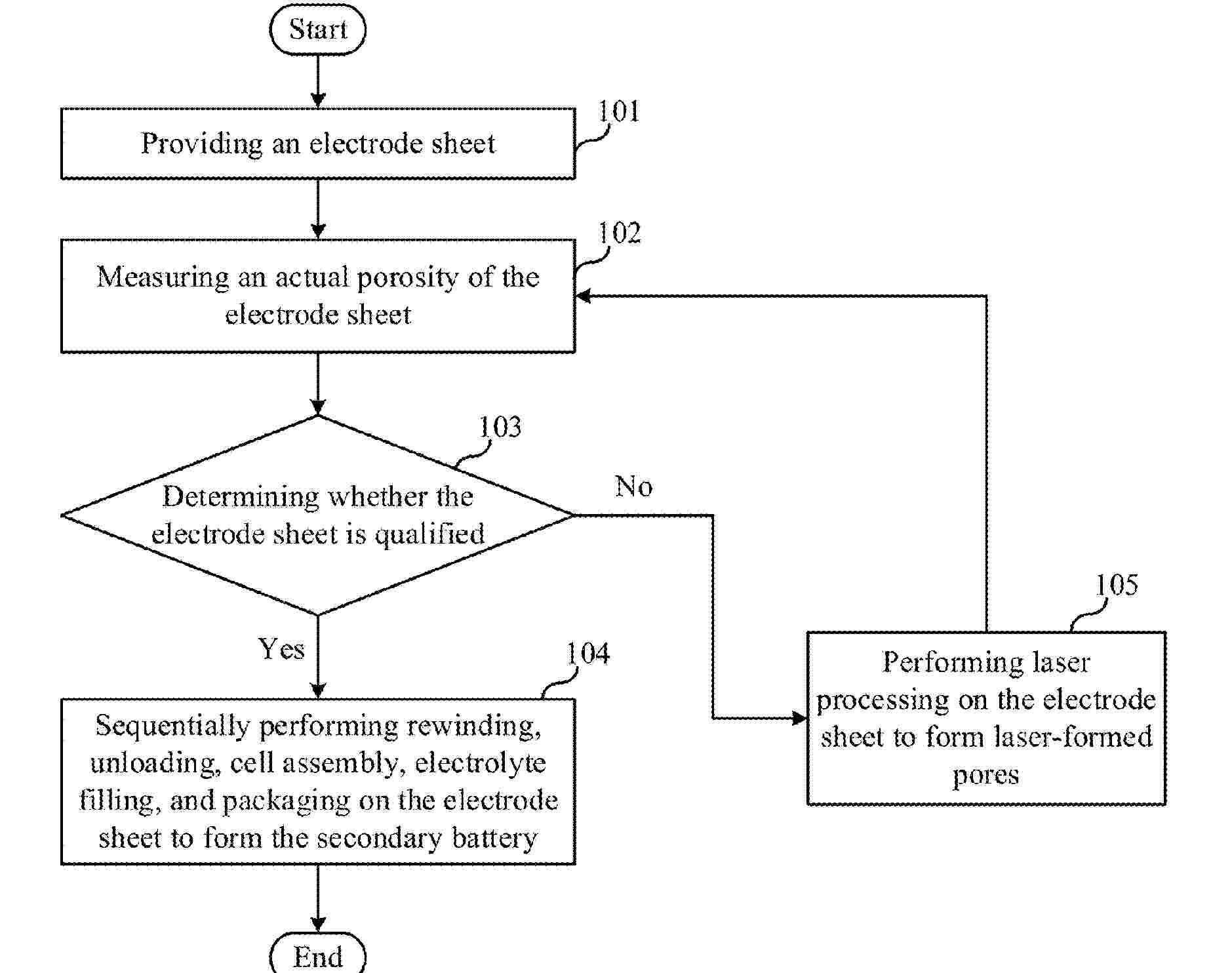
A method for manufacturing a secondary battery, a secondary battery manufactured by the method, an energy storage system, and an electric device are provided. The method includes: providing an electrode sheet; measuring an actual porosity of the electrode sheet; determining whether the electrode sheet is qualified based on the actual porosity of the electrode sheet; in response to the electrode sheet being determined to qualified, forming the secondary battery using the electrode sheet; in response to the electrode sheet being determined to be unqualified, performing laser processing to form laser-formed pores on the electrode sheet, and repeating the measuring operation and the determining operation until the electrode sheet is qualified. In this way, the uniformity of electrode sheet porosity is improved, the wettability of the electrode sheet is enhanced, and the electrical performance of the secondary battery is improved.
Resumen de: DE102024124740A1
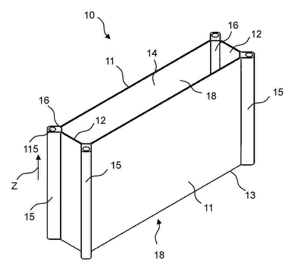
Die Erfindung betrifft ein Zellgehäuse (10) für eine prismatische Batteriezelle (20) für einen Hochvoltspeicher für ein Kraftfahrzeug, aufweisend einen Aufnahmekörper (13) zur Aufnahme einer Batteriestruktur (21) mit zwei einander gegenüberliegend angeordneten Seitenwänden (11) und zwei diese Seitenwände (12) verbindende, einander gegenüberliegend angeordnete Stirnwände (11).
Resumen de: DE102024125225A1
Eine Batteriezelle (100) weist ein zylindrisches Gehäuse (110) und einen Elektrodenwickel (120) mit einem um einen Wickelkern (190) herum gewickelten Schichtaufbau (200) auf. Zumindest eine Elektroden weist einen in Längsrichtung abstehend Stromableiter (150) auf, wobei der Elektrodenwickel (120) derart in dem Gehäuse (110) angeordnet ist, dass durch den Stromableiter (150) ein elektrischer Kontakt zu einem Pluspol bzw. Minuspol der Batteriezelle (100) ausgebildet ist. Der Stromableiter (150) weist eine Vielzahl von Laschen (151, 152) auf, welche sich in der Längsrichtung von entsprechenden der Anodenschicht und der Kathodenschicht erstrecken, wobei die Laschen (151, 152) umgebogen sind, um dadurch eine Kontaktebene an einer entsprechenden Stirnseite des Elektrodenwickels (120) für den elektrischen Kontakt zu bilden. Die Laschen (151, 152) sind in einem ersten Bereich, welcher umlaufend an einen Außenumfang des Elektrodenwickels (120) angrenzt, in einer Richtung zu dem Wickelkern (190) hin und in einem zweiten Bereich der Stirnseite, welcher umlaufend an den Wickelkern (190) angrenzt, in einer Richtung weg von dem Wickelkern (190) umgebogen
Resumen de: DE102025113884A1
Ein Verfahren der vorliegenden Offenbarung zum Herstellen einer Batterie umfasst ein Fördern eines Stapels mit Hilfe von Walzen, so dass eine Förderrichtung des Stapels, der einer Erwärmung auf eine Temperatur von 120°C oder mehr unterzogen wurde, um 45° oder mehr entlang einer Richtungsänderungswalze geändert wird, wobei der Stapel eine Basismaterialschicht und eine Elektrodenaktivmaterialschicht umfasst. Ferner beträgt bei dem Verfahren der vorliegenden Offenbarung eine Temperaturdifferenz zwischen dem Stapel nach der Erwärmung und der Richtungsänderungswalze 80°C oder weniger.
Resumen de: DE102024124988A1
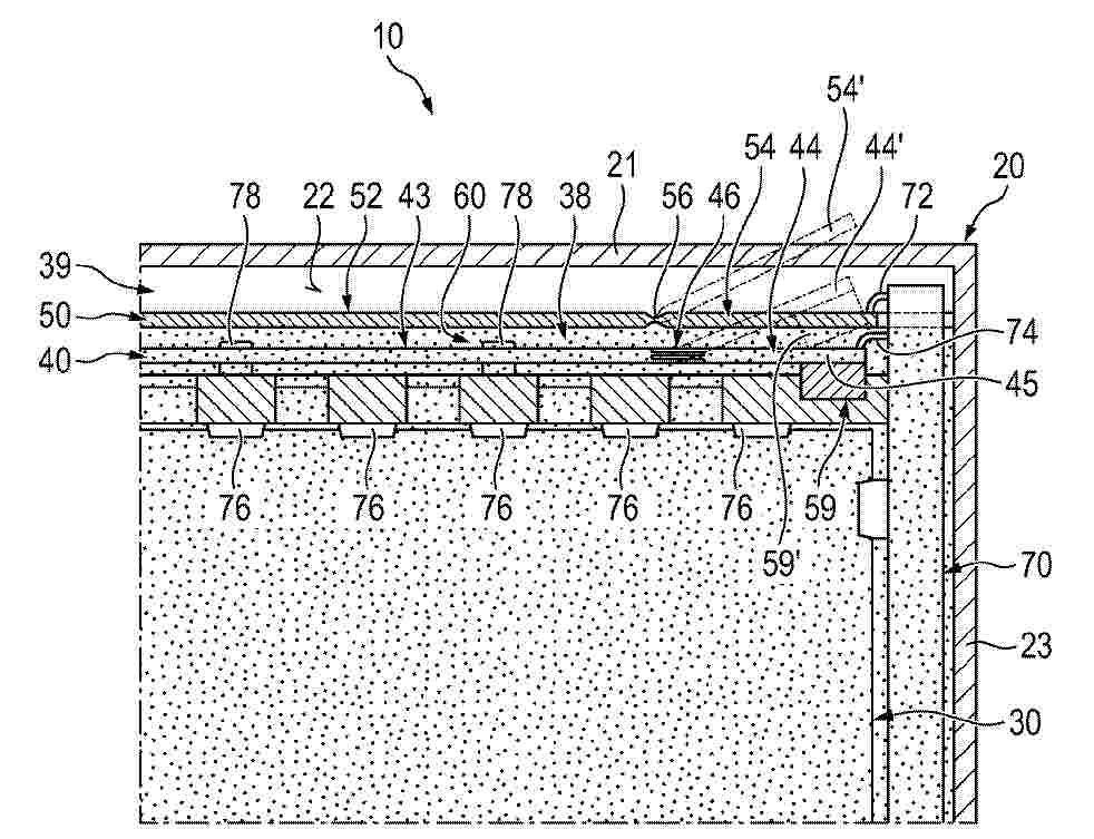
Die Erfindung bezieht sich auf eine Kfz-Traktionsbatterie (10) miteinem prismatischen Batteriegehäuse (20) mit mehreren Batteriegehäuse-Wänden (21 - 23),einer Vielzahl einzelner gestapelter Batteriezellen (30) und einer die Batteriezellen (30) elektrisch verbindenden Stromschiene (40), die einen fixierten Schienenabschnitt (43) und einen beweglichen Schienenabschnitt (44) aufweist, der mechanisch beweglich ausgebildet ist, undeinem separaten und elektrisch isolierenden Isolationsdeckel (50), der einen Zellenraum (38), in dem die Batteriezellen (30) und die Stromschiene (40) angeordnet sind, elektrisch und fluidisch abschirmt gegenüber einem Freiraum (39) innerhalb des Batteriegehäuses (20),wobei der Isolationsdeckel (50) einen statischen Deckelkörper (52) und im Bereich des flexiblen Schienenabschnitts (44) eine Isolationsdeckel-Klappe (54) aufweist, die in Bezug auf den statischen Deckelkörper (52) beweglich ist,wobei der Zellenraum (38) mit Brandschutzschaum (60) gefüllt ist, undwobei der Freiraum (39) distal des Isolationsdeckels (50) frei von Brandschutzschaum ist.
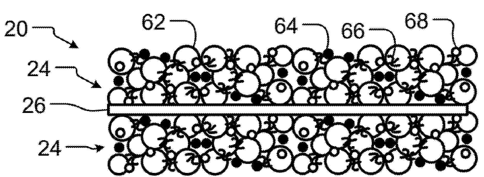
Resumen de: US20260066344A1
Disclosed is a polymer electrolyte, including: a polymer substrate; and a copolymer, wherein the polymer substrate includes a support material, and the copolymer contains cyano groups, ester groups, and sulfonic acid groups. In the present disclosure, the polymer substrate serves as a support material to provide a mechanical strength, and the function of the copolymer is to form a stable interface with positive electrodes and negative electrodes. Furthermore, the copolymer contains cyano groups, ester groups, and sulfonic acid groups, all of which are polar groups that enable improvement of the mechanical properties of the electrolyte, while having high a reduction resistance and an oxidation resistance, enabling formation of a stable SEI film with the negative electrodes and a stable CEI film with the positive electrodes, which may enable the prepared secondary battery to have a high energy density and to be able to operate cycles in the long term.
Resumen de: US20260066301A1
A battery cell includes A anode electrodes, C cathode electrodes, and S separators where C, A and S are integers greater than one. The C cathode electrodes each include a cathode current collector and a cathode active material layer arranged on the cathode current collector. The cathode active material layer comprises a cathode active material, a conductive filler, and a binder including a fibrillating binder and a co-polymer including polyacrylonitrile (PAN) and polyacrylic acid (PAA).
Resumen de: US20260066347A1
An electrochemical apparatus includes a negative electrode plate and an electrolyte. The negative electrode plate includes a negative electrode material layer, the negative electrode material layer contains silicon-carbon particles, and a surface of the silicon-carbon particles has a surface layer, where a thickness of the surface layer is X μm. The electrolyte includes a compound represented by formula I, and based on a mass of the electrolyte, a mass percentage of the compound represented by formula I is a %, 0.5≤a≤20, and 1
Resumen de: US20260066447A1
The present application provides a battery and an electric apparatus, the battery includes a cell and a support member, the support member is provided with a configuration compartment and an exhaust compartment, the cell is disposed in the configuration compartment, the cell includes a housing, an electrode, and a valve member, the valve member is disposed on a side of the housing facing the exhaust compartment and is in communication with the exhaust compartment in an open state, and the electrode is disposed on a side of the housing facing away from the valve member.
Resumen de: US20260066438A1
A method for potting the battery pack includes filling the accommodating chamber with a foam adhesive for a plurality of times prior to installation of the cover to form a pre-potted structure formed by at least one filling of the foam adhesive and a post-potted structure formed by at least one filling of the foam adhesive, in which the battery assembly is connected to the cover through the post-potted structure. A battery pack includes a case having an accommodating chamber with an opening, a battery assembly located in the accommodating chamber, a cover closing the opening, a pre-potted structure formed by foam adhesive and located in the accommodating chamber, and a post-potted structure formed by foam adhesive and located in the accommodating chamber. The battery assembly is connected to the cover through the post-potted structure.
Resumen de: DE102024124574A1
Die vorliegende Erfindung betrifft eine Filtereinrichtung (1), die ein Gehäuse (2), durch das sich ein Strömungspfad (12) für Flüssigkeit erstreckt, ein Filterelement (15) zum Filtern der Flüssigkeit, das in dem Gehäuse (2) angeordnet ist, und eine in dem Gehäuse (2) angeordnete Trocknungseinrichtung (16) mit einem Trocknungsmittel (17) zum Trocknen der Flüssigkeit aufweist. Wesentlich für die Erfindung ist, dass die Trocknungseinrichtung (16) das Filterelement (15) radial außen umlaufend umschließt, sodass die Außenmantelfläche (18) des Filterelements (15) einen ersten, von der Trocknungseinrichtung (16) überdeckten Mantelflächenabschnitt (19) und einen zweiten Mantelflächenabschnitt (20) aufweist, und dass der Strömungspfad (12) in dem Gehäuse (2) in zwei Teilpfade (21, 22) aufgeteilt ist. Die Erfindung betrifft insbesondere ein Immersionskühlsystem für ein Fahrzeug mit einer solchen Filtereinrichtung (1) sowie weiter insbesondere eine Verwendung einer solchen Filtereinrichtung (1).
Resumen de: DE102025120626A1
Ein Batteriepack weist einen Batteriestapel und einen Bandkörper auf, der die Batteriezellen des Batteriestapels zwischen dem Batteriestapel und einem Kühler, der die Batteriezellen kühlt, bindet. In dem Batteriepack ist zwischen den Batteriezellen und dem Bandkörper und zwischen dem Kühler und dem Bandkörper eine Vielzahl von wärmeleitenden Blättern vorgesehen. Zwischen den Batteriezellen und dem Bandkörper wird ein Endabschnitt jedes gekrümmten wärmeleitenden Blattes mit den Batteriezellen in Oberflächenkontakt gebracht und verbunden, und ein anderer Endabschnitt von ihnen wird mit dem Bandkörper in Oberflächenkontakt gebracht und verbunden. Dadurch kann selbst dann, wenn auf dem Bandkörper eine Krümmung oder dergleichen auftritt und Abstände zwischen den Batteriezellen und dem Bandkörper variieren, eine Verschlechterung der Kühleffizienz der gestapelten Batteriezellen eingeschränkt werden, weil eine elastische Verformung der wärmeleitenden Blätter folgt.
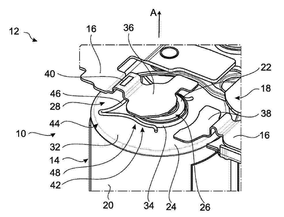
Resumen de: DE102024124370A1
Eine Baugruppe (44) besteht aus einer elektrochemischen Zelle (14) eines Hochvolt-Energiespeichers (12) und einem elektrischen Kurzschlusselement (42). Die Zelle (14) weist einen ersten Pol (22) auf, der von einem elektrisch isolierenden Dichtring (34) aus einem Kunststoffmaterial umgeben ist. Das Kurzschlusselement (42) besteht zumindest abschnittsweise aus einem elektrisch leitfähigen Material und weist einen Anlageabschnitt (46) auf, der permanent an einem zweiten Pol (24) anliegt, und einen Klemmabschnitt (48), der in einem Zustand der Zelle (14) mit normaler Betriebstemperatur permanent radial außen am Dichtring (34) anliegt und unter einer radial nach innen gerichteten Vorspannung (F) steht. In einem Zustand der Zelle (14) mit einer überhöhten Betriebstemperatur, bei der der Dichtring (34) über eine Erweichungstemperatur aufgeheizt ist, kommt der Klemmabschnitt (48) aufgrund der radialen Vorspannung (F) in direkten elektrischen Kontakt mit dem Zellfortsatz (26). Die Zelle (14) ist Teil eines Zellverbunds (10), der in einem Batteriegehäuse aufgenommen und innerhalb des Batteriegehäuses elektrisch durch ein Zellkontaktiersystem (18) kontaktiert ist.
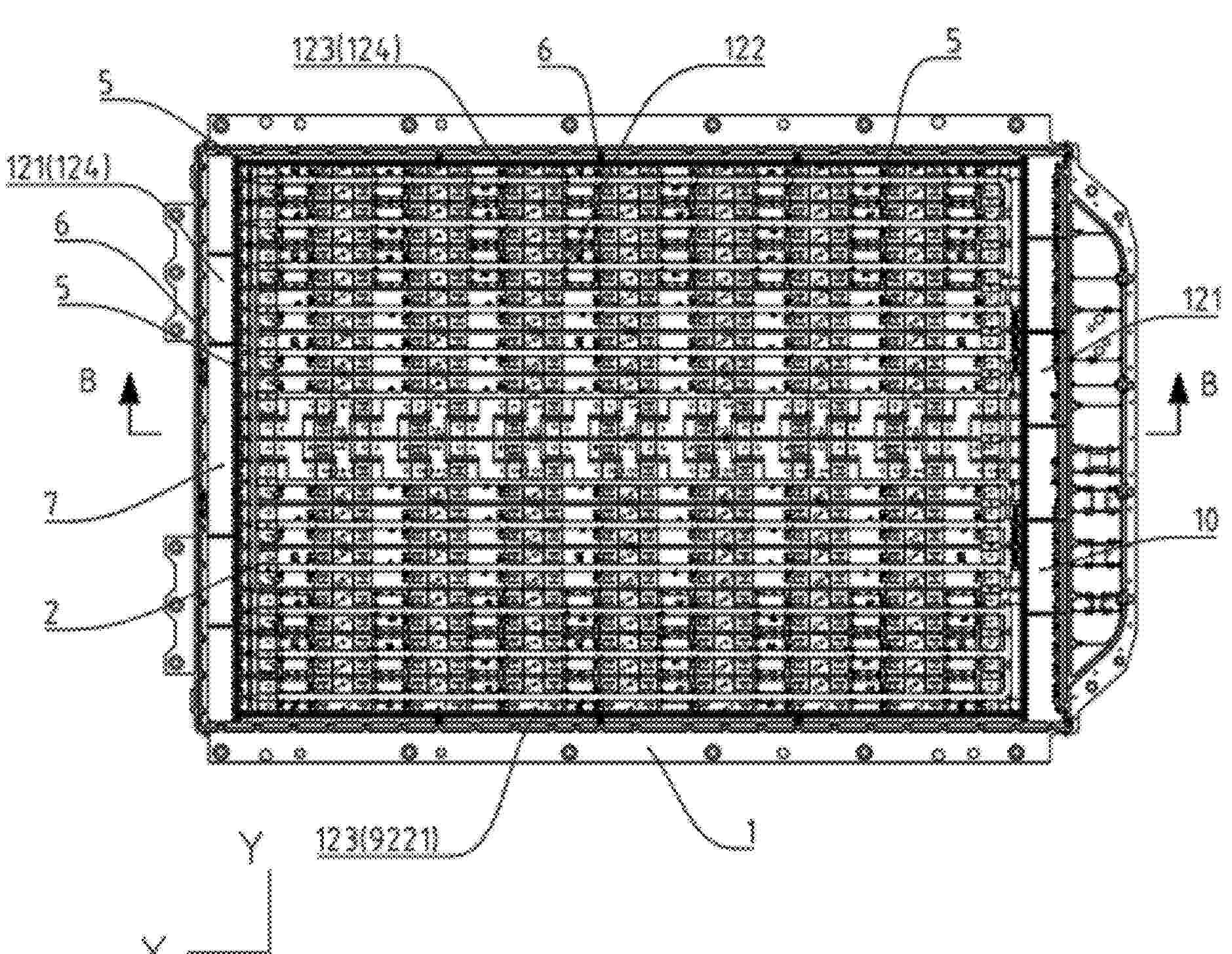
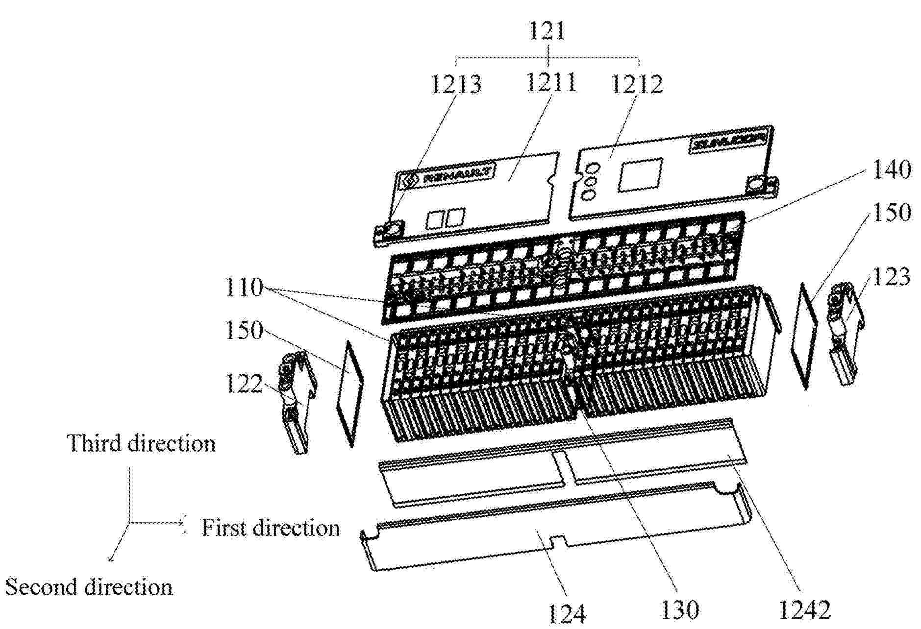
Resumen de: US20260066419A1
A battery module and a battery pack, where the battery module has a first direction, a second direction and a third direction that intersect with each other pairwise. The battery module includes a plurality of single cells and a protective casing. The protective casing includes a top cover, a first end plate, a second end plate and a plurality of side plates, where the first end plate and the second end plate are arranged at intervals along the first direction; the plurality of side plates are arranged at intervals along the second direction and connected between the first end plate and the second end plate; the top cover is connected to a same side of the first end plate, the second end plate and the two side plates along the third direction, and together they define an accommodating cavity.
Resumen de: US20260066428A1
This application provides a battery and an electric apparatus that includes the battery. The battery includes a battery unit, a box, and a reinforcing member. The box has a box body and a first box wall that covers one end of the box body. The battery unit is housed in a space formed by the box body and the first box wall. At least part of the reinforcing member is positioned on the first box wall and fixed to the box body. This structure strengthens the first box wall and keeps it stable relative to the box body through joint constraint by the reinforcing member and the box body. As a result, vibration of the first box wall is reduced, helping to minimize abnormal noise from the battery.
Resumen de: US20260066432A1
This application provides a battery and a battery module. The battery module includes a plurality of batteries and a structural adhesive. Each battery includes a battery cell and an insulating layer. The insulating layer is arranged on a side of the battery cell. One or more openings are formed in the insulating layer. The insulating layer in the one or more openings is less in thickness than other parts of the insulating layer. The structural adhesive is arranged on a surface of the battery cell, and is located in at least one of the one or more openings, and the battery and a component adjacent to battery are connected by the structural adhesive.
Resumen de: US20260066443A1
An explosion-proof valve and a box are provided in the application. The explosion-proof valve is configured for installing in the box, and includes a valve body including a breathing passage, a press cover and a breathing mechanism. The valve body is connected to the valve body, and a gap is between the press cover and the valve body. The breathing mechanism is movably connected to the press cover, and a breathing switch is formed between the breathing mechanism and the valve body. When the breathing mechanism abuts against the valve body, the breathing switch is closed, and an inside of the box is not in communication with an outside of the box. When the breathing mechanism is separated from the valve body, the breathing switch is opened, and the inside of the box is communicated with the outside of the box.
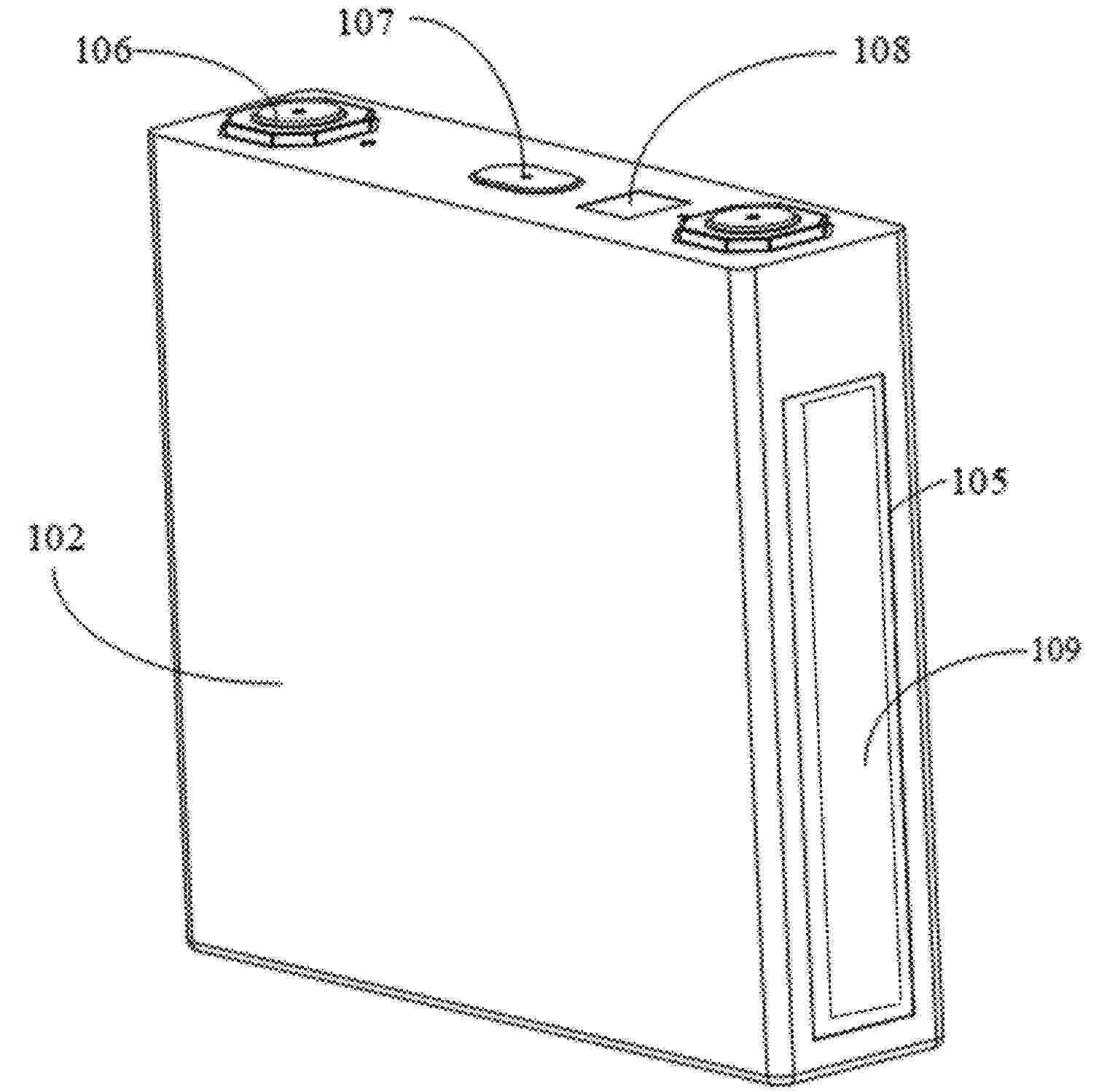
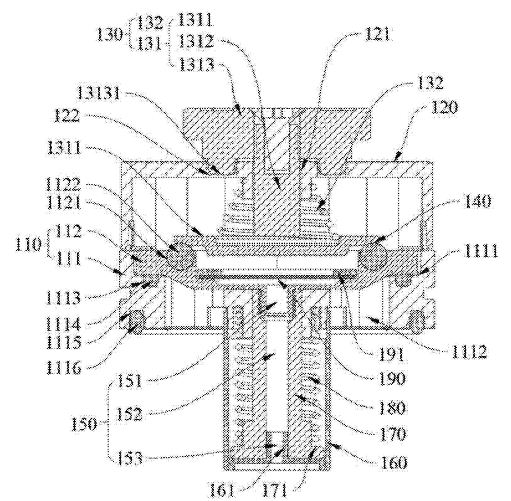
Resumen de: US20260066461A1
A separator comprises aluminum atoms and fluorine atoms, and in a 2 μm×2 μm region, a ratio A of atomic percentages of the aluminum atoms to the fluorine atoms satisfies 1≤A≤4. The separator includes a substrate, and the surface of the substrate is provided with a coating. The coating includes a plurality of spaced stripes, and an average spacing between two adjacent stripes is 1 mm to 3 mm. The separator provided in this application can improve the high-temperature cycle performance, low-temperature intermittent cycle performance, and thermal safety performance of the electrochemical apparatus.
Resumen de: DE102024125224A1
Es wird ein Verfahren zum Prüfen der Isolationsfähigkeit eines Feststoffelektrolyten (1) für eine Festkörperbatteriezelle für eine Antriebsbatterie eines Elektrofahrzeugs offenbart. Dabei wird der Feststoffelektrolyt (1) als bahnenförmiges Material bereitgestellt und mittels eines Transportsystems transportiert. Die Isolationsfähigkeit des Feststoffelektrolyten (1) wird während des Transportierens geprüft, wobei das Prüfen folgendes umfasst: Der Feststoffelektrolyt (1) wird zwischen einer ersten Walze (11) und einer zweiten Walze (12) eines Walzenpaares (10) geführt, wobei die Walzen (11, 12) zumindest an ihrer jeweiligen Oberfläche elektrisch leitfähig ausgebildet sind. Es wird elektrische Spannung an zumindest eine der ersten und zweiten Walze (11) im Hochvoltbereich angelegt, sodass zwischen der ersten und zweiten Walze (11, 12) eine Potentialdifferenz herrscht und durch einen Querschnitt des Feststoffelektrolyten (1) hindurch ein elektrischer Strom fließt. Zumindest ein elektrischer Parameter wird anhand der angelegten elektrischen Spannung gemessen und ausgewertet, um daraus einen möglichen Defekt des Feststoffelektrolyten (1) abzuleiten.
Nº publicación: DE102025123943A1 05/03/2026
Solicitante:
TOYOTA MOTOR CO LTD [JP]
TOYOTA JIDOSHA KABUSHIKI KAISHA
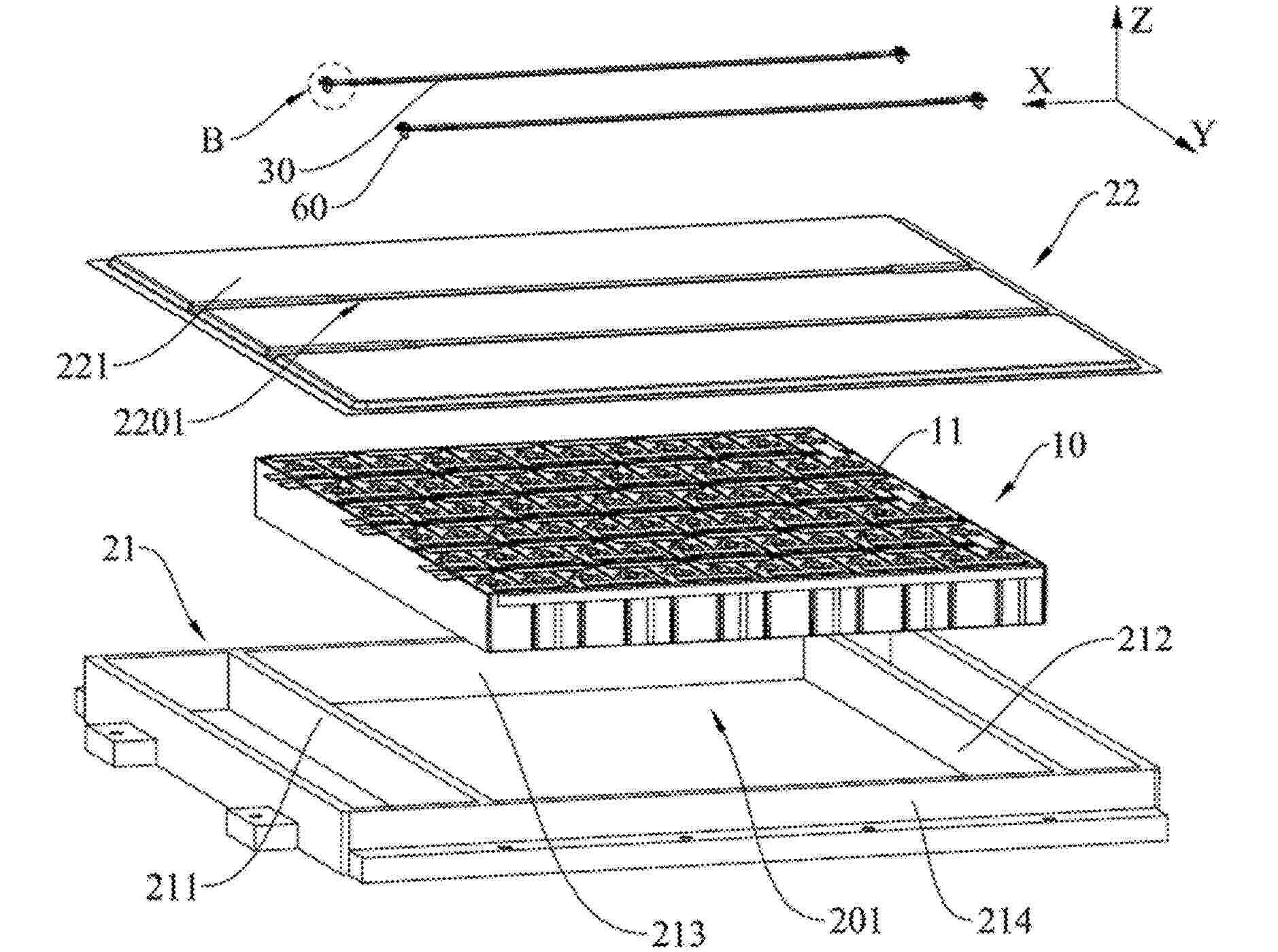
Resumen de: DE102025123943A1
Energiespeichervorrichtung mit einer Vielzahl von Energiespeicherzellen, die in einer ersten Richtung angeordnet sind, einer oberen Abdeckung, die oberhalb der Energiespeicherzellen angeordnet ist, einem Klebeelement, das die Energiespeicherzellen und die obere Abdeckung miteinander verbindet, und einem Eingriffselement, das aus Gummi besteht und zwischen den Energiespeicherzellen und der oberen Abdeckung angeordnet ist. Das Eingriffselement weist ein Paar Eingriffsabschnitte auf, die sich in der ersten Richtung erstrecken und an Stellen angeordnet sind, die das Klebeelement in einer zweiten Richtung in die Mitte nehmen, die sowohl zu der ersten Richtung als auch zu einer Oben-Unten-Richtung orthogonal ist. Jeder Eingriffsabschnitt ist mit einem Eingriffsraum versehen, der sich in die erste Richtung erstreckt.
 BOPI
BOPI
 Sede Electrónica