Si deseas distinguir tus productos, servicios o ambos de los de otra empresa, es posible que necesites una marca o nombre comercial. Descubre qué son, en qué consiste su procedimiento de registro y qué implica.

Información sobre los plazos de presentación de solicitudes de transformación de marcas de la Unión Europea en marca nacional española. Más información


Si tienes un nuevo dispositivo, producto o procedimiento que resuelva un problema técnico o tenga una ventaja práctica, existen distintas formas de protegerlo en España y en otros países. Descubre cómo hacerlo.

¿Tu innovación reside en la estética, la ornamentación o la apariencia de tu producto? Protégela mediante un diseño industrial. Descubre qué derechos confiere el registro y cómo realizar la tramitación.

Las indicaciones geográficas protegen el nombre de un producto originario de una zona geográfica, a la cual le debe una determinada calidad, reputación u otra característica. Descubre qué son, en qué consiste su procedimiento de registro y qué beneficios conceden.

Las patentes publicadas en todo el mundo son una valiosa fuente de información científica, técnica y comercial.

Si eres emprendedor/a o una empresa y quieres potenciar y mejorar la rentabilidad de tu negocio protegiendo de forma adecuada los activos intangibles de tu organización, en este espacio encontrarás lo necesario.


 1532
resultados
1532
resultados
 Última actualización
18/03/2026 [07:26:00]
Última actualización
18/03/2026 [07:26:00]


 Resultados 875 a 900 de 1532

Resumen de: WO2026045635A1
The present application discloses a mobile energy storage device and an energy storage system. The mobile energy storage device comprises a battery, a case assembly, and fasteners; the case assembly comprises a bottom case and a top case; the battery is arranged in the bottom case; first connecting columns extending in the height direction of the case assembly are arranged inside the top case; a threaded connecting hole is formed on the surface of each first connecting column facing the bottom case; first reinforcing ribs are arranged on the periphery of each first connecting column; the first reinforcing ribs extend in the height direction of the case assembly to be connected to the top case; second connecting columns extending in the height direction of the case assembly are arranged inside the bottom case; a connecting through hole is formed in each second connecting column, and the connecting through hole runs through the second connecting column and the bottom case in the height direction of the case assembly; second reinforcing ribs are arranged on the periphery of each second connecting column; the second reinforcing ribs extend in the height direction of the case assembly to be connected to the bottom case; and the fasteners pass through the connecting through holes in the height direction of the case assembly and are connected to the threaded connecting holes.

Resumen de: WO2026045628A1
Disclosed in the present application are a secondary battery, an irreversible additive for a positive electrode and a preparation method therefor, a positive electrode sheet, and an electric device. The secondary battery comprises a positive electrode sheet, wherein the positive electrode sheet comprises a positive electrode active material and an irreversible additive for a positive electrode; the irreversible additive for a positive electrode comprises an active metal ion supplement and a catalyst; and the catalyst comprises AM2O4, where A comprises a metal element having a charge of +2, M comprises a metal element having a charge of +3, and A and M are different. The irreversible additive for a positive electrode of the present application can improve the first-cycle specific charge capacity of a battery containing same and prolong the cycle life thereof.
Resumen de: WO2026045625A1
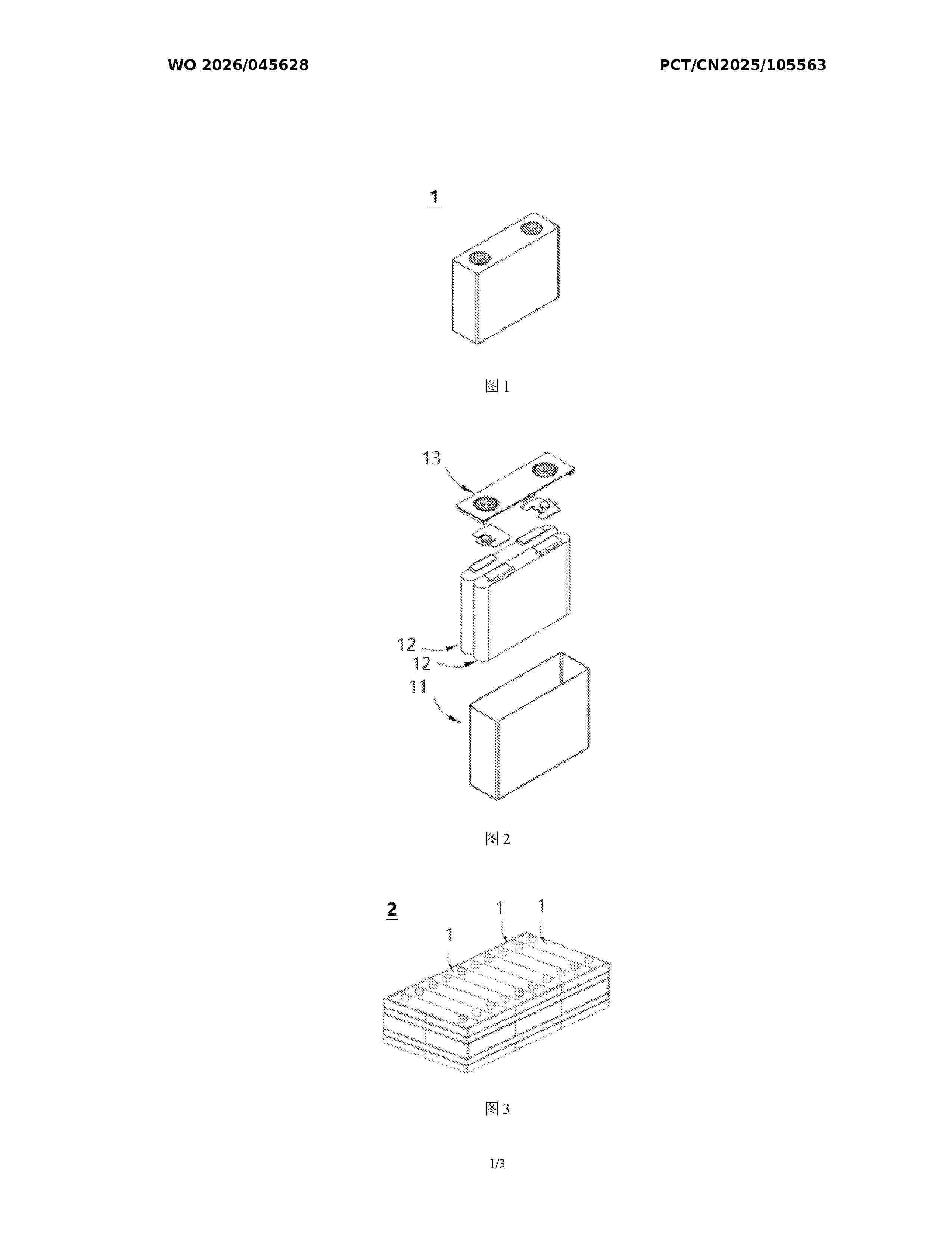
The present application discloses a cylindrical battery and an electronic device. The cylindrical battery comprises a case and an electrode assembly. The electrode assembly is arranged in the case, and the electrode assembly comprises a first electrode sheet. The first electrode sheet comprises a first hollow foil portion; the first hollow foil portion consists of a first part and a second part; the first part extends in a winding direction of the electrode assembly; the second part is formed by bending part of the first hollow foil portion in a direction in which the tail end of the first electrode sheet is close to a first end wall; the second part is connected to the first part and the first end wall of the case; and the area where the second part is connected to the first end wall is a first area. A first edge is provided at the position where the first part is connected to the second part, the first part is provided with a second edge and a third edge, and the first edge intersects the third edge to form a first folding point. The minimum distance between the first end wall and a second end wall of the case is H, the inner radius of a surrounding wall of the case is R, and the minimum distance from the first folding point to the first area is L1, wherein H+R≤L1. The service life of the cylindrical battery is prolonged by providing the second part.
Resumen de: WO2026049010A1
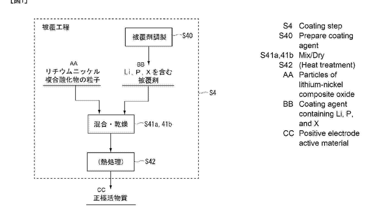
The present invention provides a positive electrode active material for a lithium ion secondary battery, the positive electrode active material having resistance against high voltage, being sufficient for practical use in a lithium ion secondary battery, and having a high battery capacity. The positive electrode active material for a lithium ion secondary battery has particles of a lithium-nickel composite oxide and a coating layer for coating at least a part of the surfaces of the particles of the lithium-nickel composite oxide. As elements other than oxygen, the lithium-nickel composite oxide contains Li, Ni, Co, and optionally an element M. The ratio of the amounts of substance of these elements is expressed as Li:Ni:Co:M = t:1-x-y:x:y (where 0.95 ≤ t ≤1.20, 0 < x ≤ 0.22, and 0 ≤ y ≤ 0.15). The coating layer contains a compound containing Li, P, and an element X (where the element X is at least one element selected from the group consisting of elements forming a hexavalent cation).
Resumen de: WO2026048970A1
This power storage unit comprises: a first electrode body and a second electrode body in each of which a positive electrode plate having a positive electrode active material layer formed on a positive electrode current collector foil and a negative electrode plate having a negative electrode active material layer formed on a negative electrode current collector foil are stacked; a first electrolyte and a second electrolyte composed of a potassium ion nonaqueous electrolyte or a sodium ion nonaqueous electrolyte; and a container that accommodates the first electrode body, the second electrode body, the first electrolyte, and the second electrolyte. The container integrally includes a first accommodation part that accommodates the first electrode body and the first electrolyte in a state in which the negative electrode plate of the first electrode body is electrically connected, and a second accommodation part that accommodates the second electrode body and the second electrolyte in a state in which the positive electrode plate of the second electrode body is electrically connected. The first accommodation part includes a positive electrode terminal insulated from the first accommodation part and electrically connected to the positive electrode plate of the first electrode body. The second accommodation part includes a negative electrode terminal insulated from the second accommodation part and electrically connected to the negative electrode plate of the second electrode body.
Resumen de: WO2026048969A1
This power storage element comprises: an electrode body in which a positive electrode plate having a positive electrode active material layer formed on a positive electrode current collector foil, is stacked with a negative electrode plate having a negative electrode active material layer formed on a negative electrode current collector foil; an electrolyte comprising a potassium ion nonaqueous electrolyte or a sodium ion nonaqueous electrolyte; a rectangular container that houses the electrode body and electrolyte; a positive electrode terminal that is disposed outside the rectangular container and is electrically connected to the positive electrode plate; and a negative electrode terminal that is disposed outside the rectangular container and is electrically connected to the negative electrode plate. The positive electrode terminal and negative electrode terminal are formed from aluminum or an aluminum alloy.
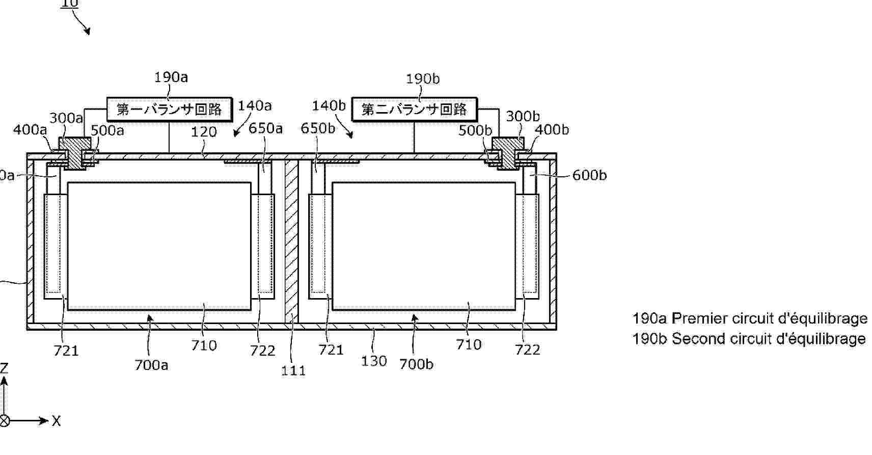
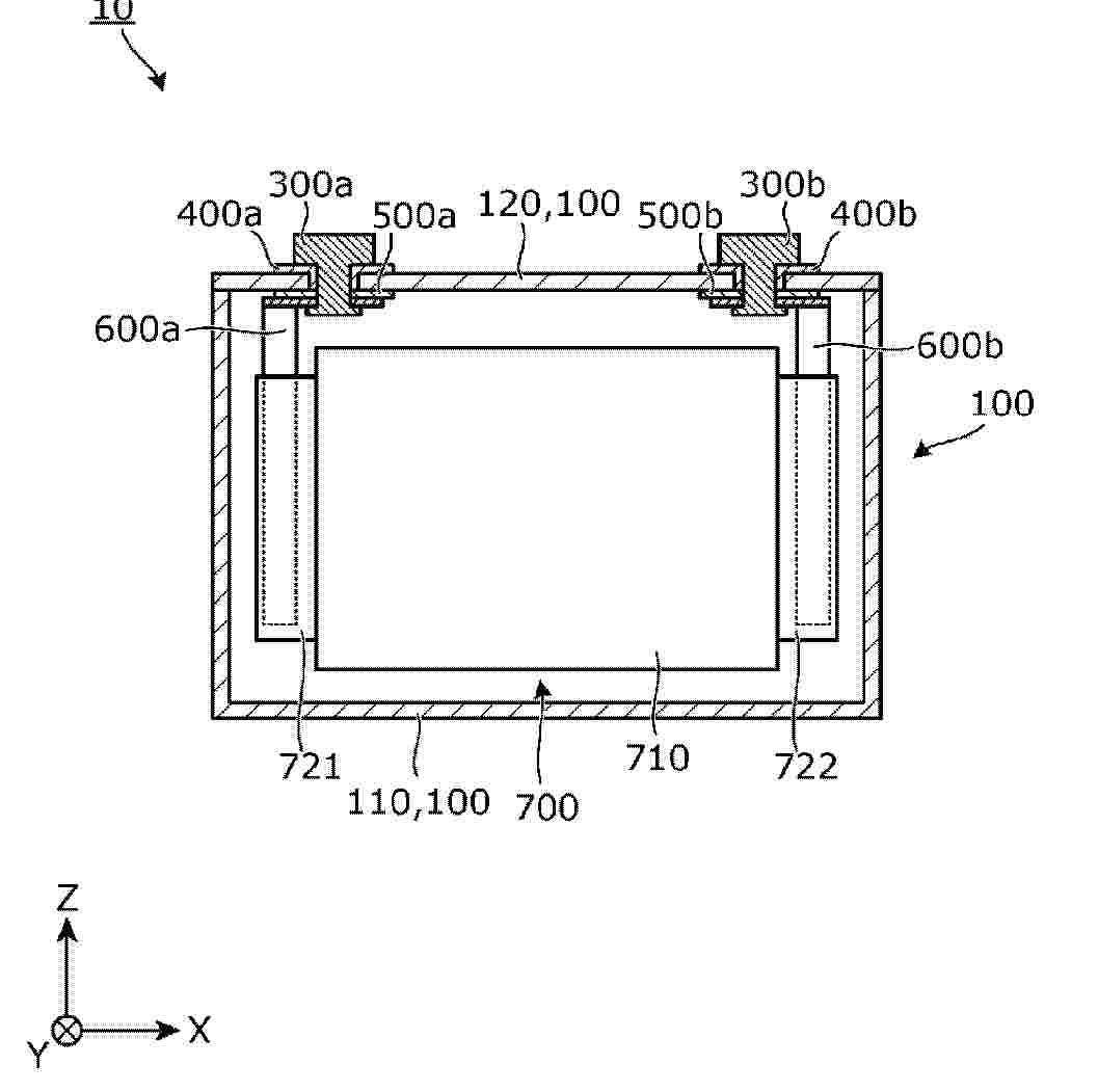
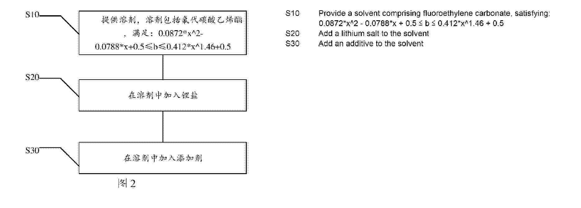
Resumen de: WO2026045104A1
A battery, a battery apparatus, and an electrical device. An electrolyte is used for the battery. The battery comprises an electrolyte and a negative electrode. The electrolyte comprises fluoroethylene carbonate. The negative electrode comprises a negative electrode active material. The negative electrode active material comprises silicon. The weight percentage of silicon in the negative electrode active material is x wt%, and the weight percentage of fluoroethylene carbonate in the electrolyte is b wt%, satisfying: 0.0872*x^2 - 0.0788*x + 0.5 ≤ b ≤ 0.412*x^1.46 + 0.5. By controlling the weight percentage b wt% of fluoroethylene carbonate in the electrolyte after formation and the weight percentage x wt% of silicon in the negative electrode to satisfy the above relationship, the battery can achieve a balance between energy density, cycling performance, and high-temperature storage performance.
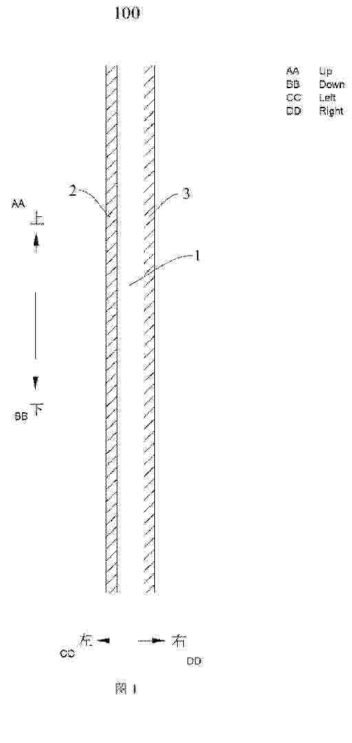
Resumen de: WO2026045105A1
An electrical device (1000), comprising a battery (400). The battery (400) comprises an electrode sheet (200) or an electrode core (300). The electrode core (300) comprises the electrode sheet (200). The electrode sheet (200) comprises a current collector (100). The current collector (100) comprises a support layer (1), a first conductive layer (2), and a second conductive layer (3). The support layer (1) comprises a main body and a conductive material. The support layer (1) is obtained by mixing and forming the main body and the conductive material. The resistance of the support layer (1) is R1, where R1 satisfies: 1 Ω ≤ R1 ≤ 1000 GΩ.
Resumen de: WO2026045112A1
Embodiments of the present disclosure provide a heat exchange apparatus, a battery pack, and an electric device. The heat exchange apparatus comprises a liquid inlet and a plurality of cooling areas, wherein the plurality of cooling areas are sequentially arranged in a first direction, and each cooling area is provided with a flow channel; in the first direction, the liquid inlet is located on one side of the plurality of cooling areas, and is separately communicated with liquid inlet ends of the cooling areas; in the first direction, flow channels of the cooling areas among the plurality of cooling areas other than the cooling area closest to the liquid inlet are each provided with at least one diversion node; and in the first direction and in a direction moving away from the liquid inlet, the number of diversion nodes in the plurality of cooling areas tends to increase.
Resumen de: WO2026045087A1
A battery apparatus comprises: a case, an explosion-proof valve and at least one battery cell assembly. The explosion-proof valve comprises: a valve body defining a pressure relief channel and a pressure relief port; a valve cover mounted on the valve body; a sealing membrane mounted on the valve body, configured to isolate the pressure relief channel from the pressure relief port, and having a sealing section for sealing the valve body; a piston arranged in the valve body and facing the pressure relief channel, the sealing section being clamped between the piston and the valve body; and an elastic member abutting against the valve cover and configured to pressing the sealing section towards the valve body by pressing the piston. With the structure, the one-way ventilation function of the explosion-proof valve is realized, the sealing performance of the explosion-proof valve in a natural state is optimized, the frequency and the total amount of gas exchange between the interior of the case and the outside are reduced, condensed water generated inside the case is reduced, and the reliability of the battery apparatus is improved.
Resumen de: WO2026045631A1
A secondary battery and an electronic device. The secondary battery comprises an electrode assembly. The electrode assembly comprises first electrode sheets, second electrode sheets, and a separator. The first electrode sheets comprise two outer first electrode sheets and an inner first electrode sheet, and the two outer first electrode sheets are respectively located on the outermost two sides of the electrode assembly. Each first electrode sheet comprises a first current collector and a first active material layer, and the first current collector comprises a first surface and a second surface. At least one outer first electrode sheet is a single-sided first electrode sheet, and the first active material layer provided on the second surface of the single-sided first electrode sheet is a first material layer. The first active material layer is provided on each of the first surface and the second surface of the inner first electrode sheet, and the first active material layer provided on each of the first surface and the second surface of the inner first electrode sheet is a second material layer. The electrical conductivity of the single-sided first electrode sheet is a S/cm, the electrical conductivity of the inner first electrode sheet is b S/cm, and a≤b. By means of the above arrangement, the risk of black spots and lithium plating on the outer electrode sheets of the electrode assembly is reduced.
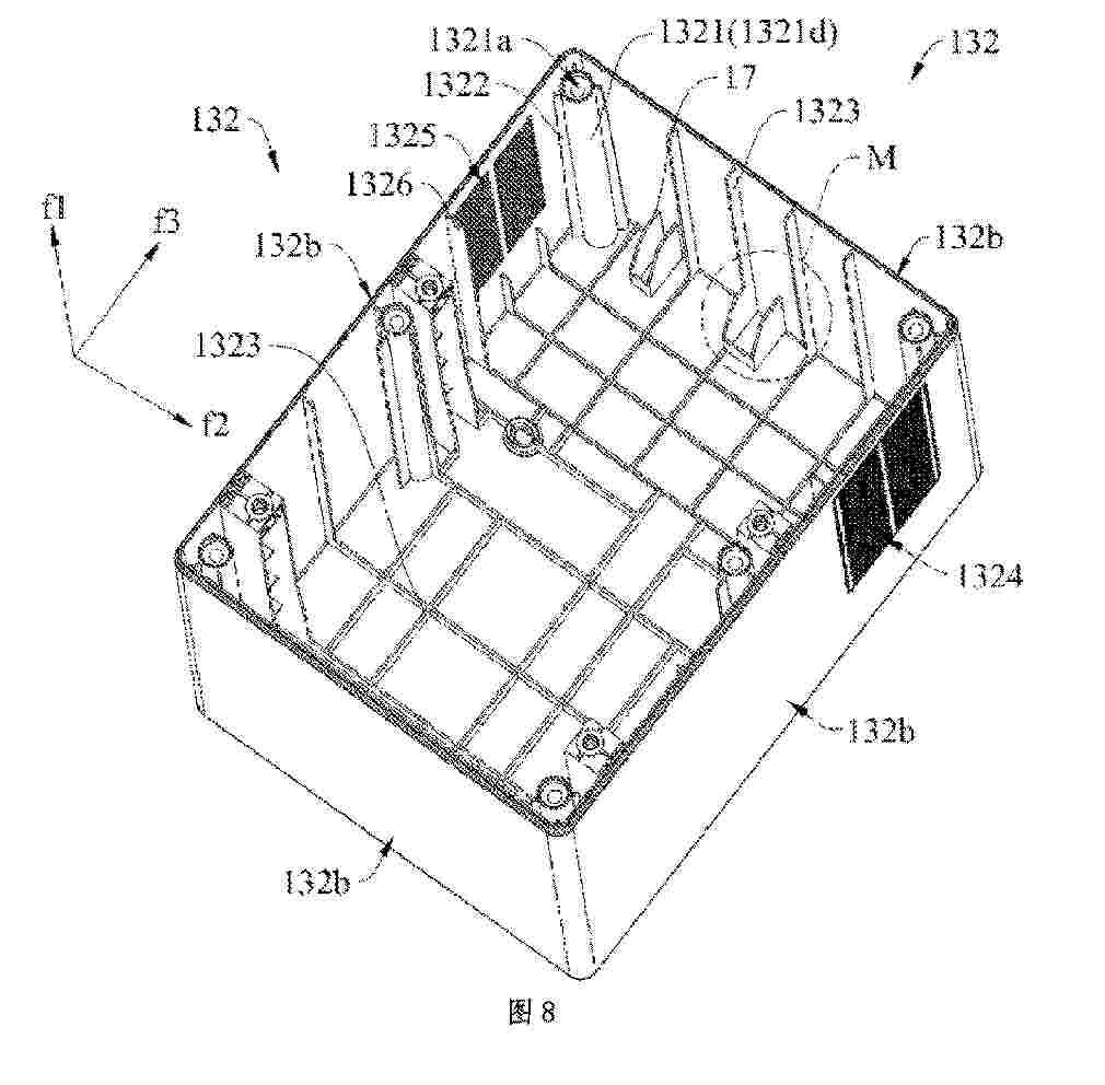
Resumen de: WO2026045638A1
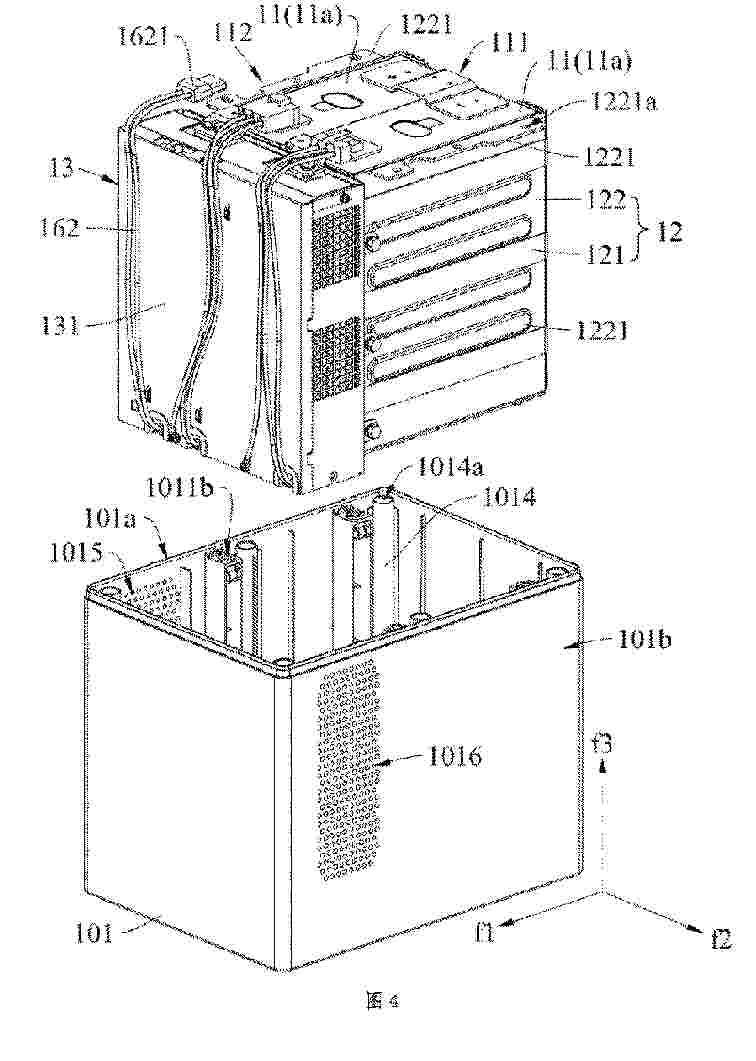
The present application discloses a portable energy storage apparatus and an energy storage system. The portable energy storage apparatus comprises a housing assembly, an energy storage unit, a fixing assembly and a control assembly. The housing assembly comprises a bottom housing and a top cover which are separately arranged. The energy storage unit is arranged inside the bottom housing and is of a cuboid structure. The energy storage unit has two small surface sides opposite to each other and two large surface sides opposite to each other. The fixing assembly and the control assembly are both arranged inside the bottom housing. The fixing assembly is at least partially arranged on the two large surface sides of the energy storage unit and clamps and fixes the energy storage unit. The fixing assembly is provided with a plurality of first positioning portions. The plurality of first positioning portions are detachably connected to the bottom housing. The control assembly is located on one small surface side of the energy storage unit and is electrically connected to the energy storage unit. The control assembly comprises a box body. The box body is provided with a plurality of first fixing portions. A plurality of second fixing portions protrude from the surfaces of the fixing assembly facing away from the large surface sides of the energy storage unit. The second fixing portions are detachably connected to the first fixing portions, so that the control assembly can be locked
Resumen de: WO2026045457A1
A battery cell and a manufacturing method therefor, and an electric device. The battery cell comprises a positive electrode sheet; the positive electrode sheet comprises a first metal oxide and a second metal oxide; the chemical formula of the first metal oxide satisfies Lia1M1Oc1, 0.2≤a1≤8.2, 1.8≤c1≤6.2, and M1 comprises one or more of V, Nb, Cr, Mo, Fe, Co, or Sn; the chemical formula of the second metal oxide satisfies Lia2Ni1-bM2 bOc2, 0≤a2≤2.2, 0≤b≤1, 0.8≤c2≤2.2, and M2 comprises one or more of Cu, Mg, Zn, Mn, Al, Zr, or Ti; and the ratio of the number of primary particles of the first metal oxide having a particle size of 5 μm-15 μm to a total number of all primary particles of the first metal oxide is 40%-90%. The present invention can reduce gas production in a battery cell and lower the risk of lithium precipitation.
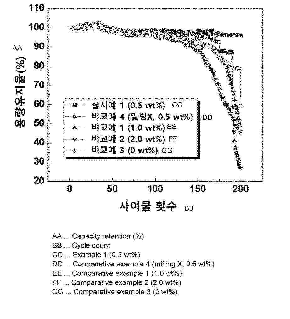
Resumen de: WO2026049105A1
The present invention relates to a secondary battery electrolyte additive comprising milled magnesium silicate, a secondary battery electrolyte comprising same, and a method for producing same and, more specifically, to magnesium silicate for a secondary battery electrolyte additive which is prepared by subjecting a mixture of magnesium silicate and a methyl ethyl ketone (MEK) solvent to primary milling using a bead mill and to secondary milling using a nano mill, as well as to a secondary battery electrolyte comprising same and a method for producing same. The present invention can provide an optimal content of the secondary battery electrolyte additive for enhancing capacity retention in a secondary battery electrolyte, and can provide a method for producing nano-sized magnesium silicate capable of reducing the process time through mechanical milling.
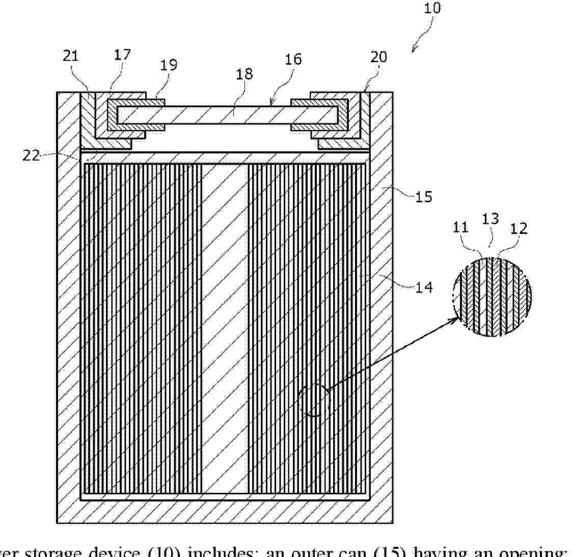
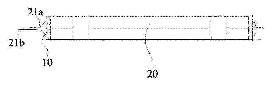
Resumen de: WO2026048779A1
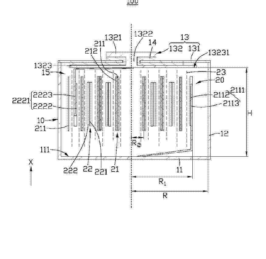
This power storage device (10) includes: an outer can (15) having an opening; an electrode body (14) which is accommodated in the outer can (15) together with an electrolyte and in which a positive electrode plate (11) and a negative electrode plate (12) are wound with a separator (13) interposed therebetween; and a sealing body (16) which closes the opening of the outer can (15). A shielding member (20) is provided between the outer can (15) and the sealing body (16). The outer can (15), the shielding member (20), and the sealing body (16) are joined. The shielding member (20) has an eaves part (21) positioned between the sealing body (16) and the electrode body (14) and extending radially toward the inside of the outer can (15).
Resumen de: WO2026048773A1
A nonaqueous electrolytic solution according to the present disclosure comprises a nonaqueous solvent, an electrolyte dissolved in the nonaqueous solvent, and particles that are insoluble in the nonaqueous solvent, the particles containing an alkali metal salt represented by formula (1), wherein M is an alkali metal and n is an integer of 1 or more. A secondary battery 100 according to the present disclosure comprises a positive electrode 5, a negative electrode 6, and the nonaqueous electrolytic solution according to the present disclosure. (1) CnH2n+1COOM
Resumen de: WO2026048772A1
A nonaqueous electrolytic solution according to the present disclosure comprises a nonaqueous solvent, an electrolyte dissolved in the nonaqueous solvent, and particles that are insoluble in the nonaqueous solvent, the particles containing an alkali metal carbonate represented by formula (1), wherein M is an alkali metal. A secondary battery 100 according to the present disclosure comprises a positive electrode 5, a negative electrode 6, and the nonaqueous electrolytic solution according to the present disclosure. (1) M2CO3
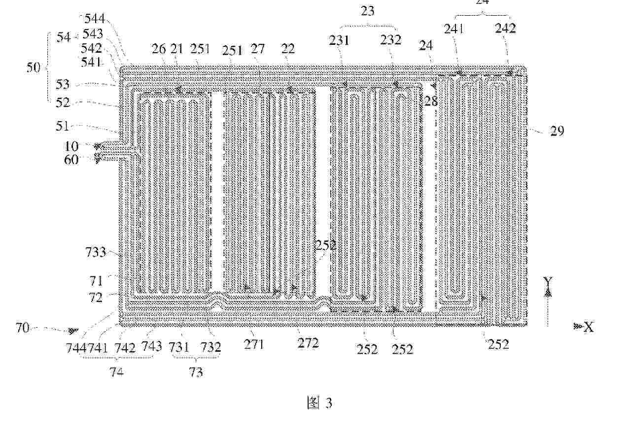
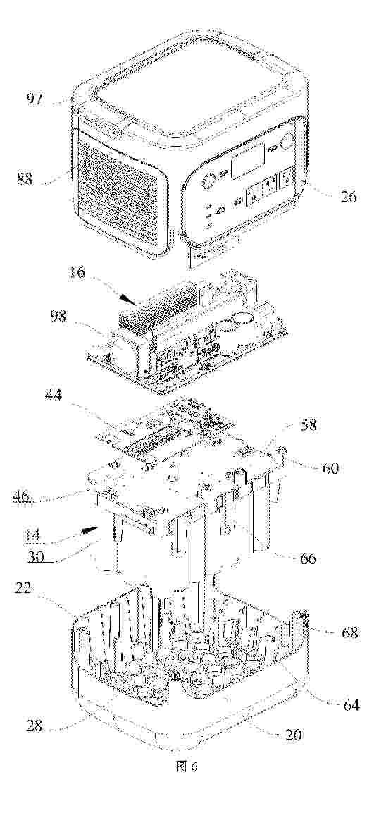
Resumen de: WO2026045084A1
An energy storage power supply (100) comprises: a housing (12), the housing (12) being provided with an accommodating cavity (18), the accommodating cavity (18) being provided with a first support (20), the first support (20) being provided with first accommodating slots (28), and the bottom of each first accommodating slot (28) being provided with a first through hole (34); battery cells (14), the battery cells (14) being located in the accommodating cavity (18), the battery cells (14) being provided on the first support (20), each battery cell (14) comprising a main body (30), and one end of the main body (30) being embedded in a corresponding first accommodating slot (28); a second support (46) fixedly connected to the housing (12), the second support (46) being provided on the side of the battery cells (14) facing away from the first support (20), and the battery cells (14) being sandwiched between the first support (20) and the second support (46); and an inverter (16), the inverter (16) being located in the accommodating cavity (18) and being electrically connected to the battery cells (14).
Resumen de: WO2026045086A1
The embodiments of the present application belong to the technical field of batteries, and provide an explosion-proof valve, a battery device, an energy storage device and an electric device. The battery device comprises a case, at least one battery cell assembly accommodated in the case, and an explosion-proof valve mounted on the case. The explosion-proof valve comprises a valve body in which a pressure relief channel and a pressure relief port are formed; a valve bonnet mounted on the valve body; a sealing film which is mounted on the valve body and is used for separating the pressure relief channel from the pressure relief port, and which comprises a first section, a second section and a sealing section that are connected in sequence, wherein the first section is connected to the valve body, a cavity in communication with the pressure relief port is formed between the second section and the valve body, and the sealing section is used for sealing the valve body; a piston disposed in the valve body, wherein the sealing section is sandwiched between the piston and the valve body; and an elastic member, one end of the elastic member abutting against the valve bonnet, and the other end of the elastic member pressing the sealing section towards the valve body by means of pressing the piston.
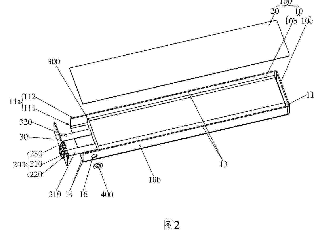
Resumen de: WO2026045083A1
Provided is a battery housing (100), comprising a casing (10). The casing (10) is provided with an accommodation cavity (11) having a cavity opening (11a) and used for placing an electrode core (300). The cavity opening (11a) comprises a first cavity opening (111) located on an end wall surface (12) of the casing (10) and a second cavity opening (112) located on a side wall surface (13) of the casing (10), the first cavity opening (111) and the second cavity opening (112) being in communication with each other. The battery housing (100) can overcome the technical defect that laser cannot be placed vertically during the welding process of terminals (240) and tabs of the electrode core (300), thereby facilitating the laser welding of the terminals (240) and the tabs of the electrode core (300), and improving working efficiency. Also provided are a secondary battery (1000) and a manufacturing method therefor.
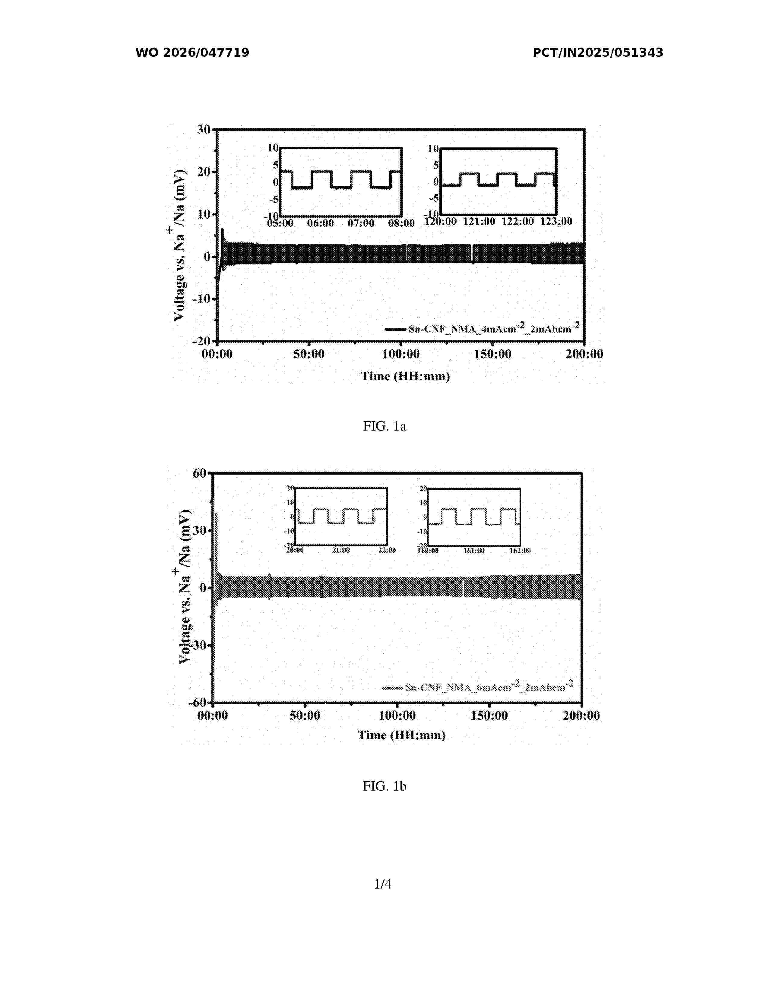
Resumen de: WO2026047719A1
The present invention generally relates to the metal batteries. The present invention discloses sodium-plated host material comprising sodium-plated or bonded with metal modified electrospun carbon nanofiber, wherein the metal is selected from tin (Sn), silicon (Si), germanium (Ge), zinc (Zn), cobalt (Co) and lead (Pb). The present invention also discloses a process for preparation of sodium-plated host material and a full cell comprising the sodium- plated host material.
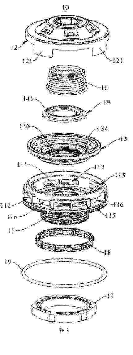
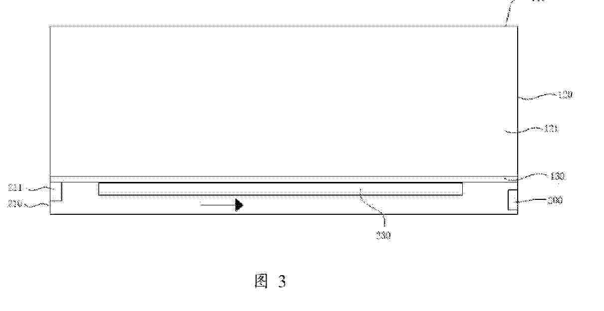
Resumen de: WO2026045489A1
An energy storage enclosure and an energy storage system. The energy storage enclosure comprises an enclosure body, a heat dissipation assembly, and a heat dissipation fan (200). The enclosure body is provided with an installation space (121), the installation space (121) being used for accommodating an electronic device (300) such as an energy storage module. The heat dissipation assembly is disposed on the enclosure body and has a heat dissipation space independent of the installation space (121), the heat dissipation space being used for exchanging heat with the installation space (121). The heat dissipation fan (200) is disposed on the heat dissipation assembly and is used for blowing air into the heat dissipation space, so as to achieve heat exchange between the heat dissipation space and the outside environment. Upon activation of the heat dissipation fan (200), a heat dissipation airflow blown out by the heat dissipation fan (200) enters the heat dissipation space and exchanges heat with the heat dissipation assembly. The heat dissipation assembly performs heat exchange by means of connection with the enclosure body, and the enclosure body then performs heat exchange with the electronic device (300) in the installation space (121), thereby ensuring the operating temperature of the electronic device in the installation space (121).
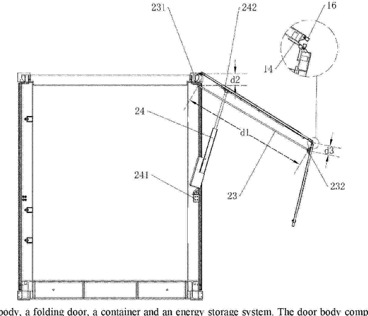
Resumen de: WO2026045450A1
A door body, a folding door, a container and an energy storage system. The door body comprises a first door panel and a second door panel, wherein the first door panel is adapted to be rotationally connected to a first beam; the second door panel is rotationally connected to the end of the first door panel away from the first beam; in a first state, a first included angle is formed between the first door panel and the second door panel, and both the first door panel and the second door panel are adapted to be connected to a door frame and close the door frame; in a second state, a second included angle is formed between the first door panel and the second door panel, the second door panel is spaced apart from the door frame, and the first included angle is greater than the second included angle; and during switching from the first state to the second state, the end of the second door panel close to the first door panel moves in a direction away from the door frame, and the end of the second door panel away from the first door panel moves toward the first beam. By means of applying the door body to a container, the space utilization rate of the container is improved.
Resumen de: WO2026045484A1
An end plate installation apparatus and a battery production device. The end plate installation apparatus is used to sleeve an end plate onto a positive terminal of a battery cell. The positive terminal of the battery cell is provided with a tab. The tab has a first end portion and a second end portion. The first end portion is connected to the positive terminal, and the second end portion is an end away from the positive terminal. The end plate installation apparatus comprises: a fixture, an end plate clamping assembly, a first tab holding assembly, and a second tab holding assembly. The fixture is used to support and fix the battery cell. The end plate clamping assembly is used to clamp the end plate and drive the end plate to move. The first tab holding assembly has a holding state and an avoidance state. When in the holding state, the first tab holding assembly contacts a middle portion of the tab to prevent the tab from sagging, and when in the avoidance state, the first tab holding assembly avoids a sleeving path of the end plate. The second tab holding assembly is configured such that, when the first tab holding assembly is in the avoidance state and the second end portion of the tab passes through the end plate, the second tab holding assembly contacts the second end portion of the tab to prevent the tab from sagging.
Nº publicación: WO2026048749A1 05/03/2026
Solicitante:
PANASONIC ENERGY CO LTD [JP]
\u30D1\u30CA\u30BD\u30CB\u30C3\u30AF\u30A8\u30CA\u30B8\u30FC\u682A\u5F0F\u4F1A\u793E
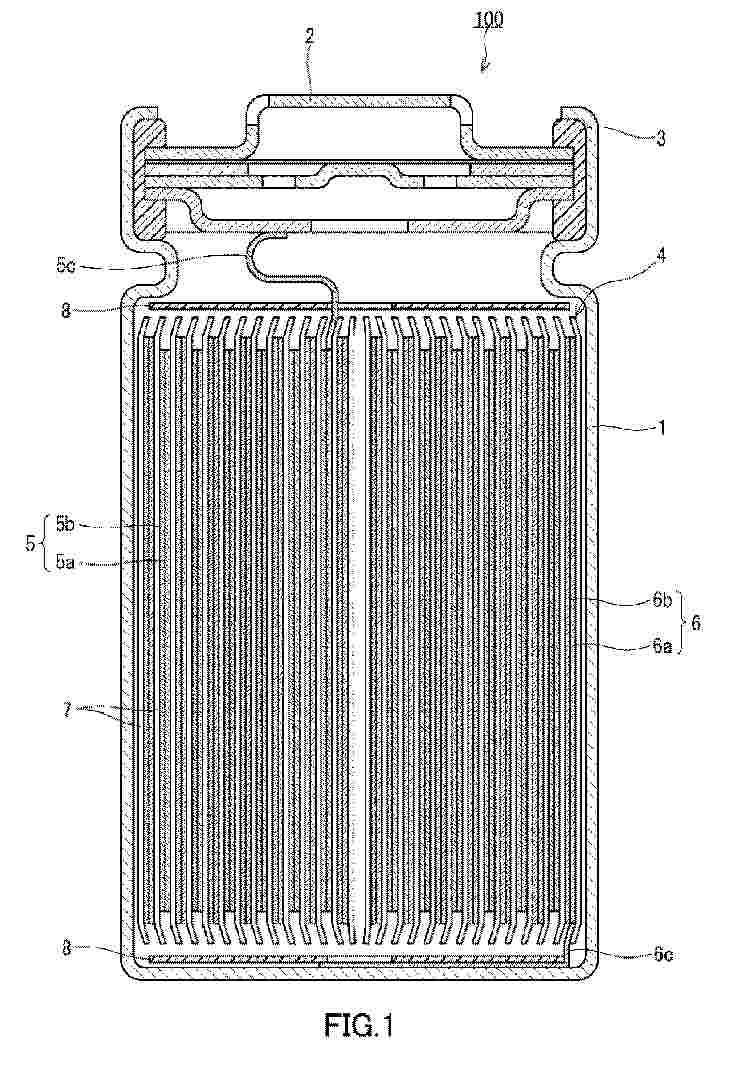
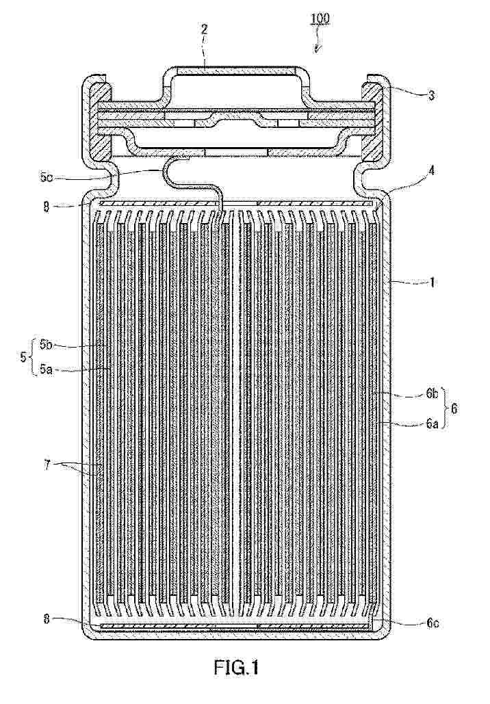
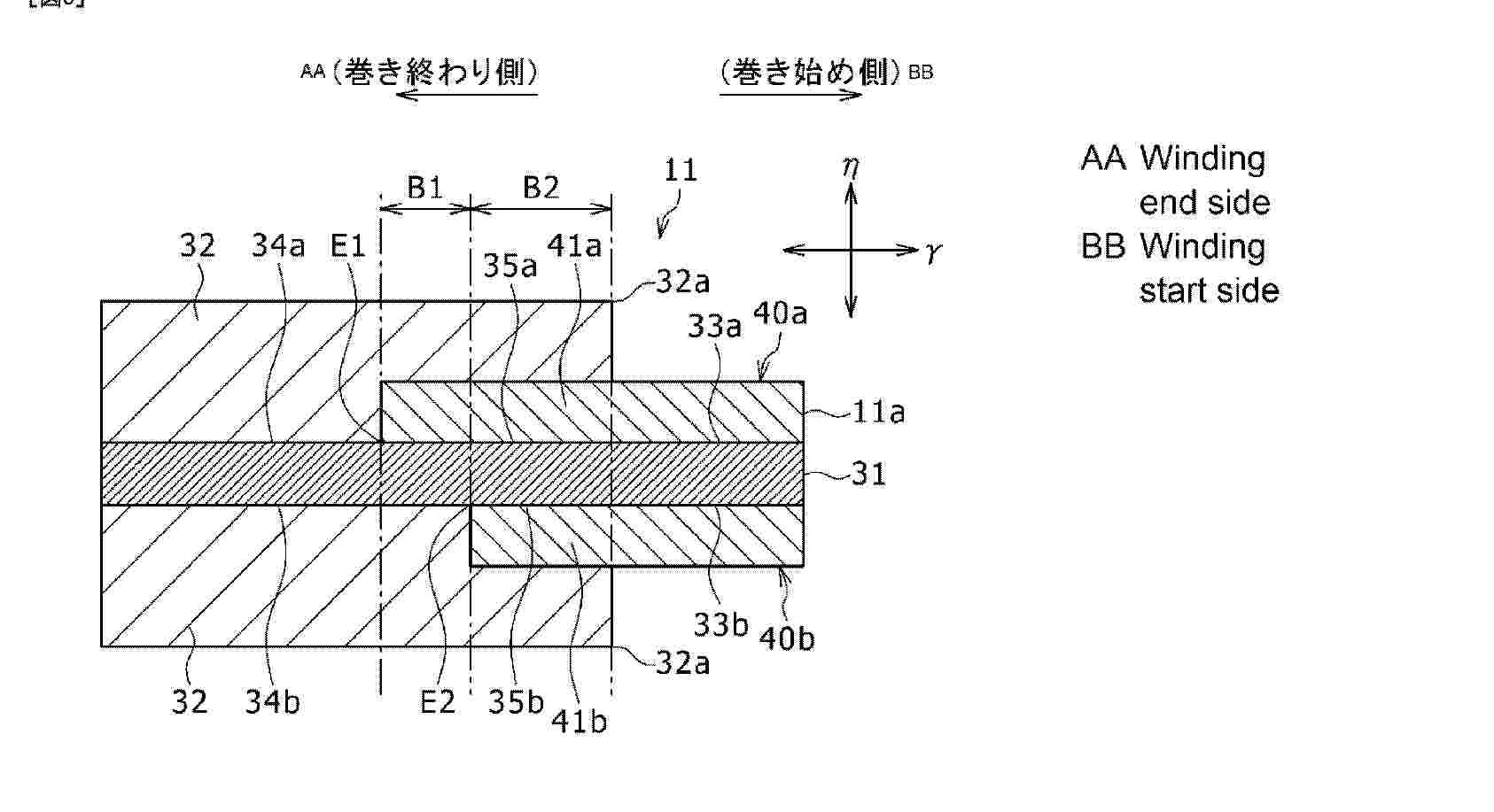
Resumen de: WO2026048749A1
This nonaqueous-electrolyte secondary battery comprises an electrode body in which a positive electrode (11) and a negative electrode are arranged with a separator interposed therebetween. The positive electrode (11) and/or the negative electrode comprises mixture layers (32) disposed on both surfaces of an electrode core (31) and protective layers (40a, 40b) disposed on both surfaces of the electrode core (31). At least some part of each of mixture-layer non- formation portions (33a, 33b) disposed on both surfaces of the electrode core is covered with the protective layer. On each thickness-direction side of the electrode core, some part of the protective layer is disposed between the electrode core (31) and the mixture layer (32). On both surfaces of the electrode core, the positions (E1, E2) of the boundaries between the mixture-layer formation portions (34a, 34b), in which the mixture layers are directly formed on the electrode core (31), and protective-layer formation portions (35a, 35b), in which the protective layers are formed, are arranged so as not to coincide with each other along the thickness direction.
 BOPI
BOPI
 Sede Electrónica