Si deseas distinguir tus productos, servicios o ambos de los de otra empresa, es posible que necesites una marca o nombre comercial. Descubre qué son, en qué consiste su procedimiento de registro y qué implica.

Información sobre los plazos de presentación de solicitudes de transformación de marcas de la Unión Europea en marca nacional española. Más información


Si tienes un nuevo dispositivo, producto o procedimiento que resuelva un problema técnico o tenga una ventaja práctica, existen distintas formas de protegerlo en España y en otros países. Descubre cómo hacerlo.

¿Tu innovación reside en la estética, la ornamentación o la apariencia de tu producto? Protégela mediante un diseño industrial. Descubre qué derechos confiere el registro y cómo realizar la tramitación.

Las indicaciones geográficas protegen el nombre de un producto originario de una zona geográfica, a la cual le debe una determinada calidad, reputación u otra característica. Descubre qué son, en qué consiste su procedimiento de registro y qué beneficios conceden.

Las patentes publicadas en todo el mundo son una valiosa fuente de información científica, técnica y comercial.

Si eres emprendedor/a o una empresa y quieres potenciar y mejorar la rentabilidad de tu negocio protegiendo de forma adecuada los activos intangibles de tu organización, en este espacio encontrarás lo necesario.


 859
resultados
859
resultados
 Última actualización
04/05/2026 [07:11:00]
Última actualización
04/05/2026 [07:11:00]


 Resultados 275 a 300 de 859

Resumen de: CN121802472A
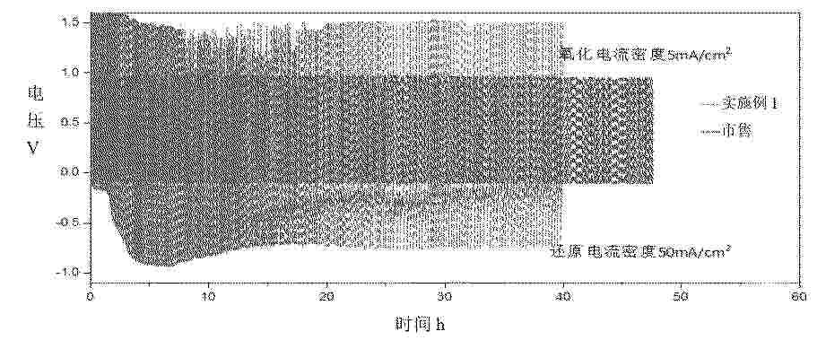
0001 本申请实施例公开了一种阴极催化剂及其制备方法、阴极气体扩散电极和电解槽,该阴极催化剂包括催化剂载体和负载于所述催化剂载体表面的活性物质,所述催化剂载体包括具有氧空位的金属氧化物,所述催化剂载体与所述活性物质的接触界面形成有异质结。本申请通过以具有氧空位的金属氧化物负载活性物质,在电解水制氢系统停机、负载波动或故障等情况下,阴极出现反极化现象时,金属氧化物具有较低的氧化还原电位,会先于活性物质被优先氧化,从而保护活性物质的活性位点不被氧化,进而减轻氧化反应对阴极气体扩散电极的破坏。

Resumen de: CN121797352A
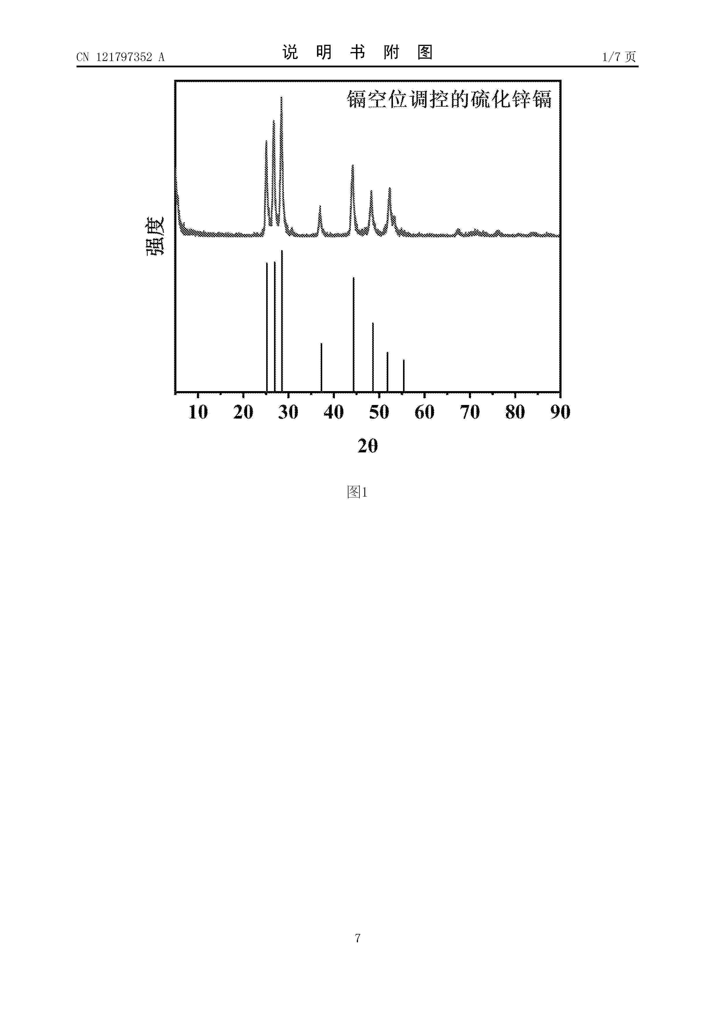
本发明涉及光催化析氢领域一种镉空位调控的硫化锌镉催化剂的制备及其应用。本发明的目的是提供一种制备工艺简便、成本低廉且具有高效光催化析氢性能的镉空位调控的硫化锌镉催化剂,以提升光催化析氢效率,缓解当前能源危机下对清洁能源的迫切需求。所采用的方法:以醋酸锌、氯化镉、硫脲、聚乙烯吡咯烷酮和水合肼溶液为原料,采用一步水热合成方法,制备了镉空位调控的硫化锌镉催化剂可适用于光催化析氢领域且具有较高的催化活性和稳定性。
Resumen de: CN121802477A
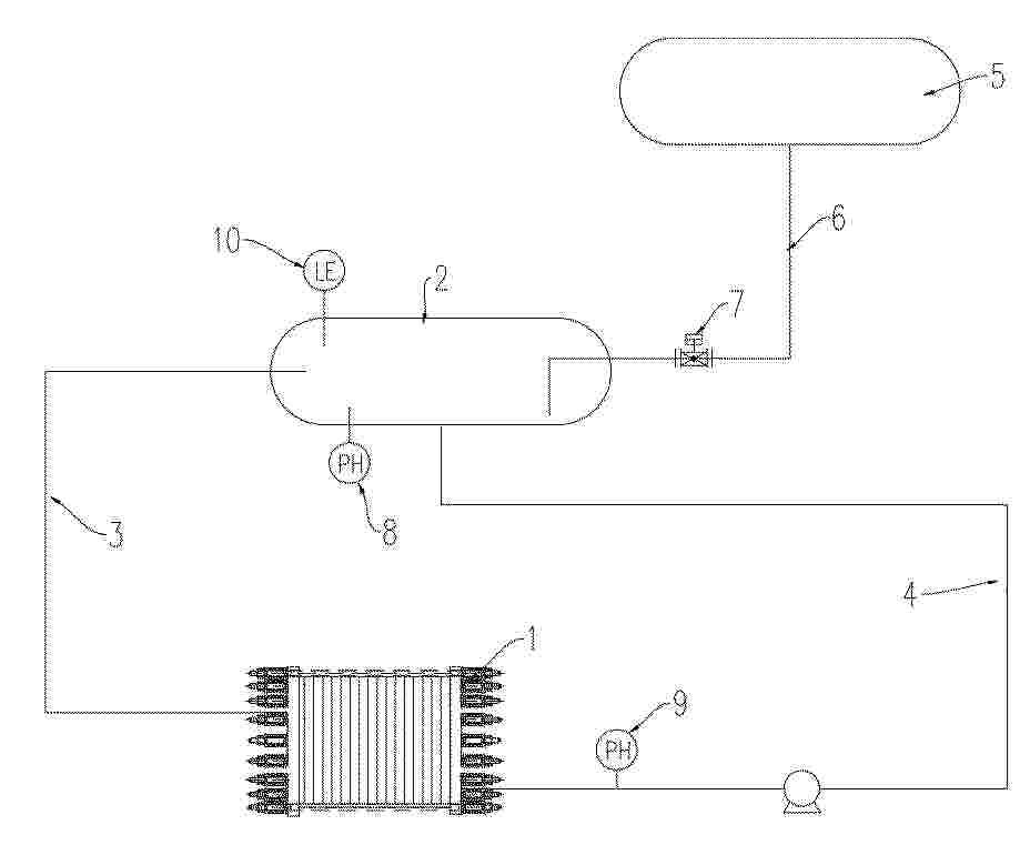
本发明公开了一种电解水制氢系统碱液浓度在线控制系统及方法,涉及电解水制氢技术领域。装置包括碱性电解槽、气液分离单元、多参数监测单元、补水模块以及智能控制模块;液位检测模块用于实时检测气液分离器内的碱液液位高度,pH在线检测模块实时检测碱液的pH值;智能控制模块预存碱液液位高度与pH值的对应关系模型,该模型覆盖28%‑32%浓度区间的碱液特性,控制模块根据液位检测模块和pH在线检测模块的实时数据,判断碱液浓度状态,并驱动补水模块向气液分离器或电解槽内自动补水,将碱液浓度维持在预设的28%‑32%区间内。通过液位高度与pH值的联动监测,实现了碱液浓度的在线精准控制,提升了电解水制氢的效率和稳定性,降低了人工操作成本。
Resumen de: CN121802481A
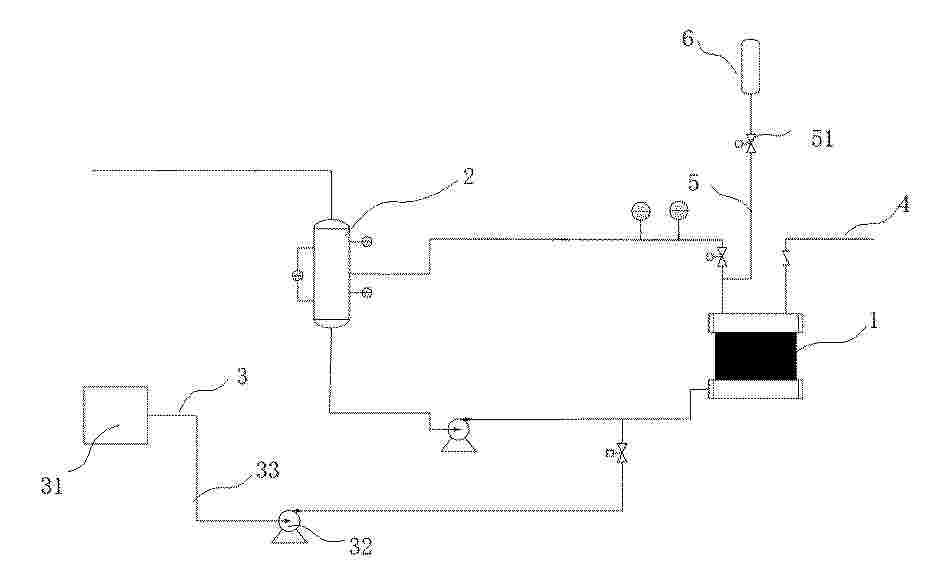
0001 本发明涉及阴离子交换膜电解水系统领域,具体涉及一种阴离子交换膜电解水系统用停机保护系统及其保护方法。一种阴离子交换膜电解水系统用停机保护系统,包括:电解槽;碱液循环回路;纯水供给单元,所述纯水供给单元通过所述碱液循环回路对电解腔室内输送纯水以置换和/或稀释电解槽内残留的碱液;监测组件,所述监测组件设于所述电解槽的一侧,所述监测组件与所述碱液循环回路、纯水供给单元和电解槽内的电解系统均通过电信号相连接。本申请通过监测组件实时获取电解系统运行状态,当监测到停机状态时,触发纯水供给单元通过碱液循环回路向电解腔室输送纯水,避免膜因碱液作用发生降解,有效保护阴离子交换膜的结构完整性。
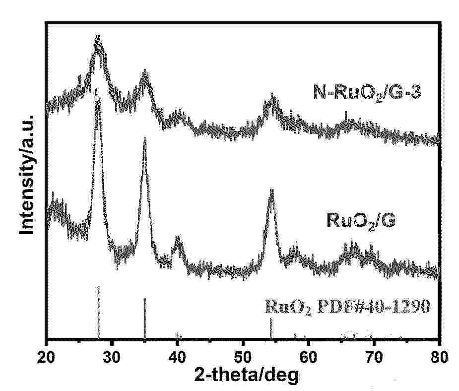
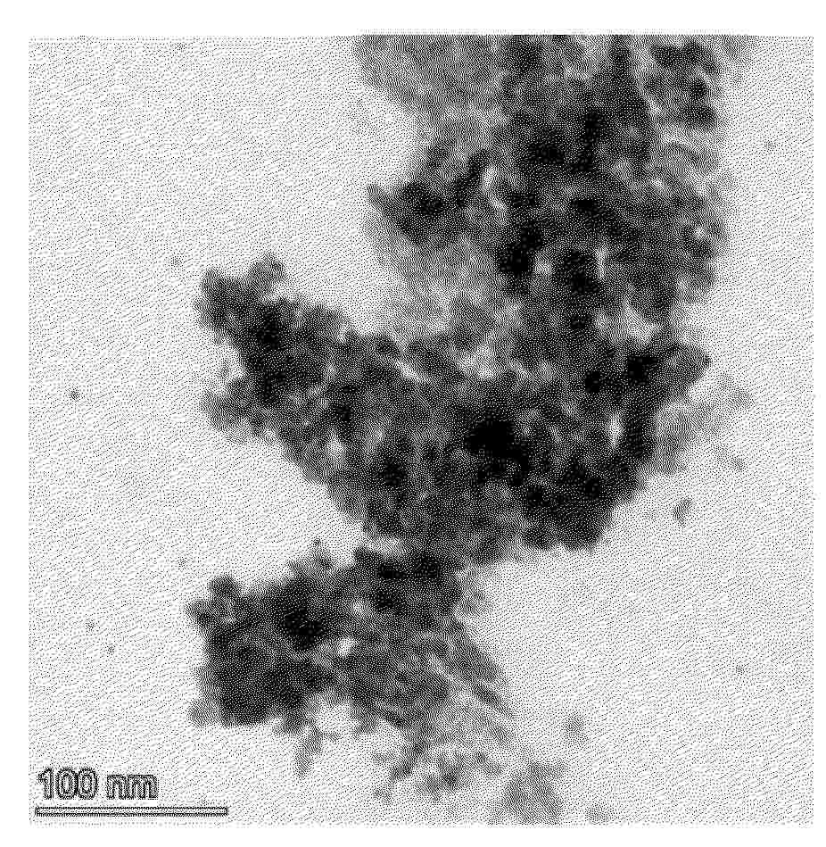
Resumen de: CN121802457A
本发明公开了一种氮掺杂氧化钌负载石墨烯电催化剂及其制备方法与应用,属于电催化剂技术领域,本发明将氮源、钌源和石墨烯加入水中,搅拌,冷冻干燥,得到前驱体;将所述前驱体于空气氛围中升温至450~700℃,退火,得到氮掺杂氧化钌负载石墨烯电催化剂。本发明通过将氧化钌颗粒负载在石墨烯表面同时引入氮元素,即得到纳米片负载均匀分布的纳米小颗粒,其比表面积大,暴露出更多的活性位点,氮元素的引入进一步调节原子结构并优化了原子结构,抑制了氧化钌在阳极的过度氧化,从而极大地提高了氧化钌的电催化析氧性能和稳定性。
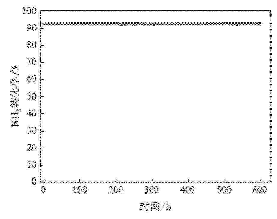
Resumen de: CN121797347A
0001 本申请公开了一种Ru合金单原子催化剂及其制备方法和在氨分解制氢中的应用,属于催化剂制备技术领域。该催化剂以Fe或Ni为主体金属,通过控制金属间电子耦合及表面原子配位,实现Ru以单原子形式锚定于Fe或Ni金属表面或近表面位点,该催化剂在450 ℃下对氨分解的转化率可达90%以上。该催化剂可通过浸渍‑表面置换法结合低温氢还原法制备,工艺简单,易于规模化。Ru原子与Fe或Ni之间形成稳定的Ru–Fe(或Ru–Ni)配位键,能够有效降低氨分解中N–H键断裂能垒,显著提高氨分解活性与抗烧结稳定性。本申请实现了在极低贵金属用量下的高效氨分解制氢,具有良好的成本优势和工业应用前景。
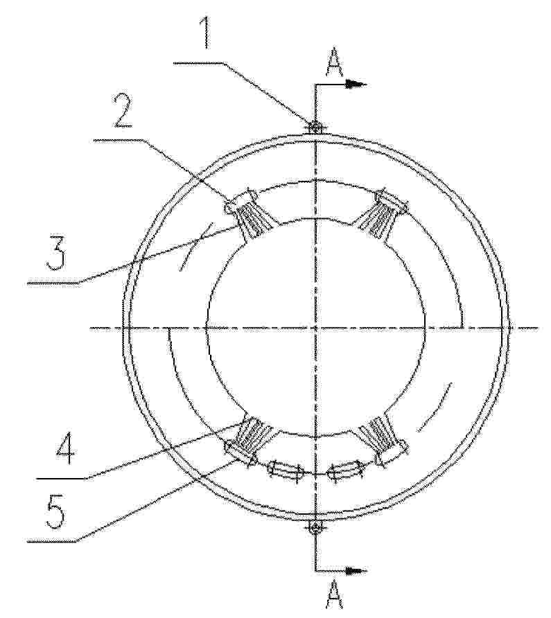
Resumen de: CN121802437A
0001 本发明提供了一种非纯水制氢、氧电解气体发生装备,包括:多个环形极框,所述环形极框的外侧壁上设置有定位夹紧结构;相邻的所述环形极框之间设置有密封垫片;所述环形极框的两侧分别设置有固定环和环形槽;所述环形极框上设置有气液流道和电解液流道,所述气液流道和电解液流道沿环形极框的径向相对布置,所述气液流道由多个呈扇形分布的气液孔道组成,所述环形极框的内孔为电解小室,气液孔道呈锥形且细端与电解小室连通;电解小室中设置有选择性离子交换膜,所述选择性离子交换膜两侧均设置有电极,且相邻的环形极框之间的电极之间设置有主极板。解决了非纯水制氢、氧电解气体发生装备的腐蚀、定位错位、电解效率低、电解液分布不均的问题。
Resumen de: CN121802450A
本发明公开了一种基于电解水析臭氧的集成式阳极及其制备方法,其特征在于,包括如下步骤:将Pt黑催化剂与Nafion树脂分散在去离子水和乙醇的分散液中得到料浆;将所述料浆涂覆在膜上,得到Pt黑涂层;将Pt黑涂层热压转印到质子交换膜上,制成半膜电极;提供有阳极钛毡和所述半膜电极的电解槽,所述半膜电极有催化剂Pt黑的一侧面向所述阳极钛毡,阳极侧通入NaCl电解液,在1.3~1.8 V的电势窗口中进行CV扫描,在钛毡上沉积得到β‑PtO2,即得到所述基于电解水析臭氧的集成式阳极。本发明基于PEM析臭氧电解槽的一般设计,利用电化学的方法直接在阳极Ti毡上快速、高效、温和的生成稳定的商业化的β‑PtO2。
Resumen de: CN121797330A
一种基于熔盐法合成Ga掺杂NiTiO3光催化剂的方法,它涉及一种光催化剂的制备方法。它是要解决现有的溶胶/凝胶法合成的Ga‑NiTiO3光催化全水分解制氢的产氢速率低的技术问题。本方法:将Ga2O3、NiO和TiO2研磨混合均匀,再与由KCl与NaCl混合而成的助熔剂研磨混合均匀,得到前驱体;前驱体煅烧后、用水洗去熔盐和杂质,再过滤干燥,得到Ga掺杂NiTiO3光催化剂。该光催化剂全水分解制氢时的产氢和产氧速率分别达到10.2和4.9 μmol·h‑1,比溶胶凝胶法合成的Ga‑NiTiO3和未掺杂的NiTiO3分别提高了5.6和2.4倍,且具有稳定性和重复使用能力,可用于光催化产氢领域。
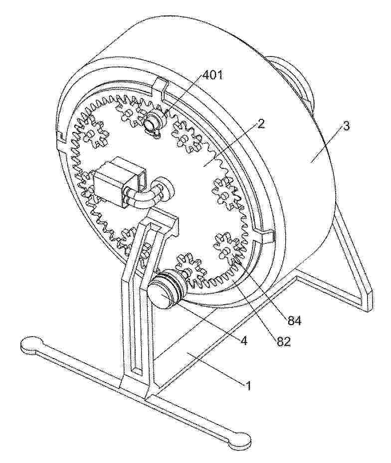
Resumen de: CN121800308A
0001 本发明涉及纳米气泡制备领域,尤其涉及一种基于纳米气泡制备富氢水的装置。本发明提供一种基于纳米气泡制备富氢水的装置,能够使得纳米氢分子气泡与水能够更加充分和更加均匀地接触而形成氢水,以便于提高水的溶氢速率和含氢量,还能及时补充消耗的氢气,提高氢水的制备效率。一种基于纳米气泡制备富氢水的装置,包括有主支撑架、侧边圆板和旋转圆框等;主支撑架上固定连接有侧边圆板。旋转圆框转动带动翻搅板转动,从而翻搅架和翻搅板能够对旋转圆框内部的水和纳米氢分子气泡进行混合搅动,使得纳米氢分子气泡能够与水充分接触而形成氢水,以便于提高水的溶氢速率。
Resumen de: CN121797025A
0001 本申请公开了一种气液分离设备和电解制氢系统,用于分离电解制氢系统中的气液,气液分离设备包括:腔体组件和分离组件;腔体组件包括:容纳腔体,容纳腔体被构造具有气液进口、液体出口和气体出口;其中,气液进口被构造于容纳腔体的顶部;分离组件包括:喷淋管道、导流挡片和气流通道,喷淋管道竖直设置于容纳腔体内,气流通道连通喷淋管道和气液进口;导流挡片位于喷淋管道内,以使得导流挡片和喷淋管道之间形成气液挤压空间;喷淋管道的出液端设置有多个喷淋口。本技术方案,能够对气液混合物进行至少三次的气液分离,以大大地提高气液分离效率。同时还能对气液混合物进行彻底分离。
Resumen de: CN121797382A
本发明公开了一种高产氢活性的RNCDs/g‑C3N4光催化材料及其制备方法与应用,制备方法包括以下步骤:将芦竹、尿素和过氧化氢加入到去离子水中进行水热反应,得到碳点RNCDs;将尿素在真空、且氮气保护下进行煅烧,得到g‑C3N4;将g‑C3N4溶于去离子水中,加入碳点,超声至完全溶解后进行煅烧,得到RNCDs/g‑C3N4光催化材料。本发明以废弃芦竹这一生物质为原料,通过尿素辅助可控水热法制备氮掺杂高结晶度碳点,再采用原位煅烧法将其负载于g‑C3N4纳米片上,构建出三维分级结构的RNCDs/g‑C3N4光催化材料,该材料在可见光下展现出卓越的光催化析氢性能。
Resumen de: CN121811991A
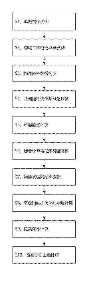
0001 本发明公开了一种基于AlAs/ZrS<2>范德华异质结的电催化氢还原反应设计方法,属于电催化分解水制氢技术领域。本发明通过第一性原理计算构建AlAs/ZrS2异质结模型,设置20 Å真空层;基于单层AlAs平移形成四种堆叠构型;基于结合能筛选稳定结构;计算氢吸附吉布斯自由能。研究发现相比于Pt等贵金属催化剂以及传统的异质结催化剂,无贵金属的二维AlAs/ZrS2范德华异质结催化剂具有成本低廉,晶格失配低等特点,结果表明具有最负结合能的AZ‑2构型Al原子上吸附具有较低的氢吸附自由能,也证明了其良好的HER催化活性。
Resumen de: CN121800309A
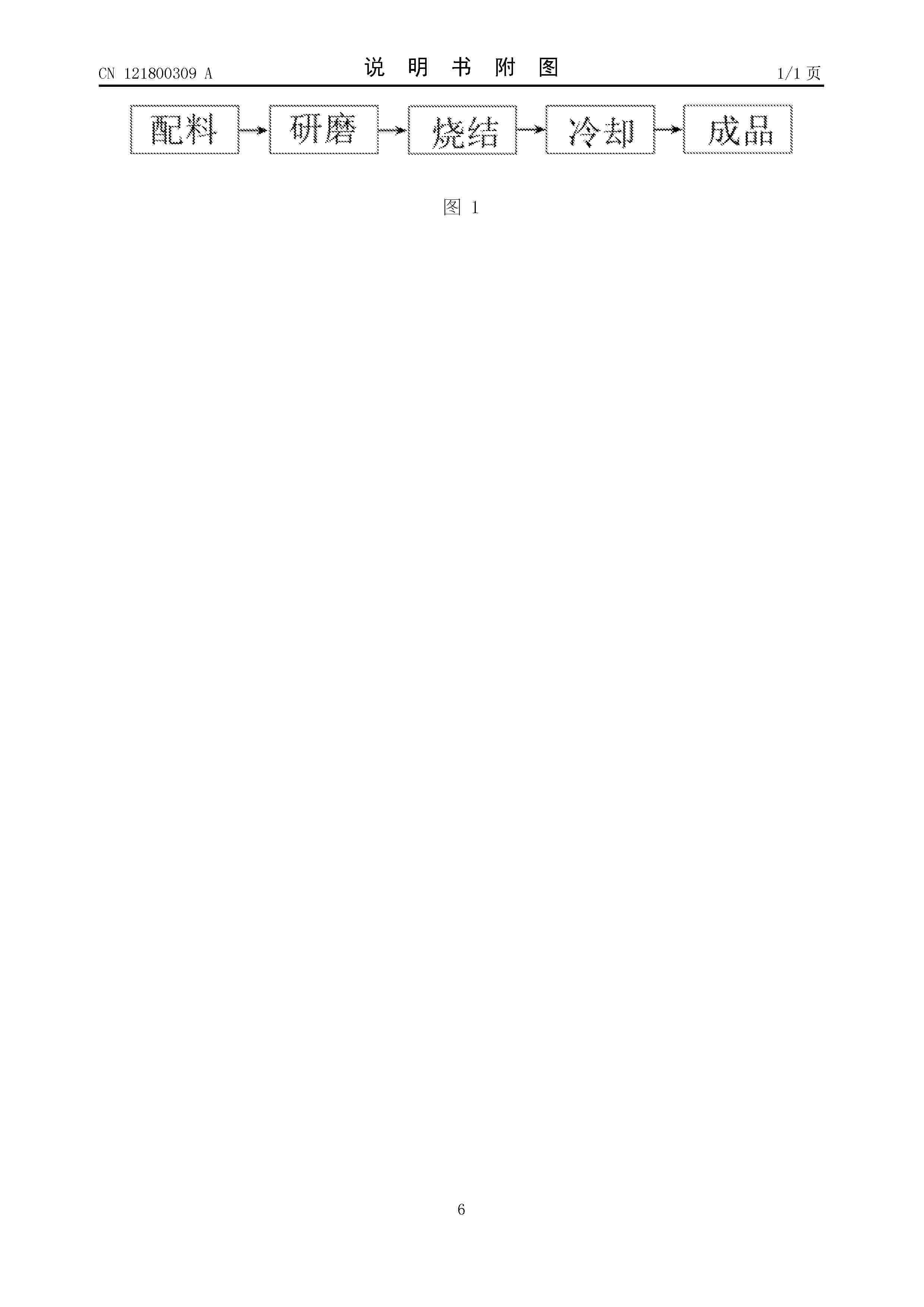
0001 本发明涉及功能材料技术领域,具体为一种用于制备富氢水的复合材料及其制备方法和应用,所述复合材料由托玛琳石和镁橄榄石按质量比(1:9)至(4:6)混合,经研磨、高温烧结制成。有益效果是:该材料在与水接触时,能协同、持续地释放高浓度氢分子(氢值可达3000ppb以上),并有效减缓其逃逸,显著延长富氢水的保质期。同时,该材料能发射4‑16微米的远红外线,使处理后的水呈现弱碱性(pH约8.5)、总溶解固体含量低(TDS约20),并形成小分子团水结构。本发明还提供了该材料的制备方法,其工艺简单、环保。该复合材料可广泛应用于制备保健饮用水、功能性饮品或作为水处理滤芯的填充材料,具有高效、稳定、多功能集成和安全便利的优点。
Resumen de: CN121802460A
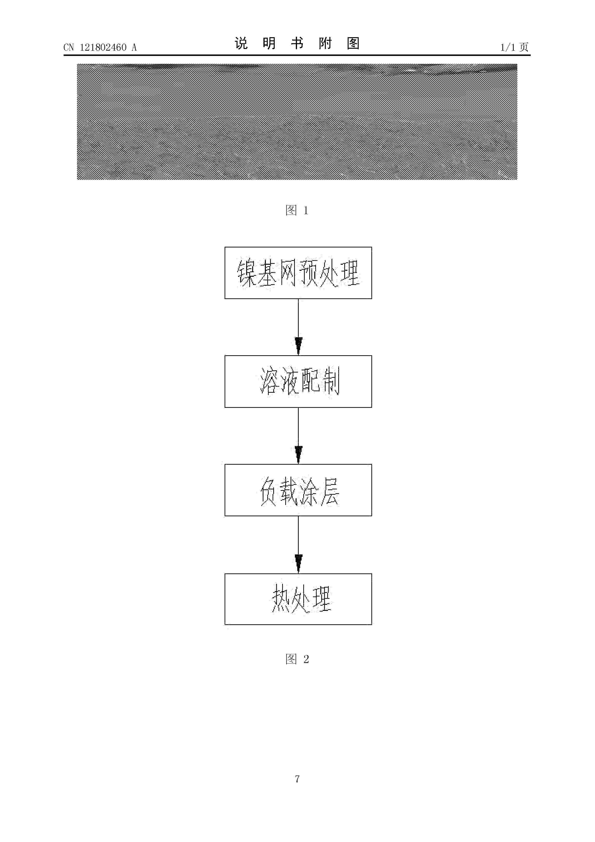
0001 本发明涉及一种镍基含钌钕铁涂层的析氢反应电极及其制备方法,属于电化学能源转换技术领域,一种镍基含钌钕铁涂层的析氢反应电极,包括基网以及设置在基网表面的涂层,所述基网为多孔镍材料,所述涂层中包含钌、钕和铁三种元素。本发明钌提供接近铂的优异HER本征活性;铁有效调节钌的电子结构,优化氢吸附自由能,并大幅降低成本;钕作为稀土元素,其掺入能引入晶格畸变和大量活性缺陷,增强结合力;通过使用廉价的铁和少量钕,大幅降低了贵金属钌的用量(最低至4%),使电极成本远低于纯钌或纯铂;多孔镍基底提供了巨大的比表面积和稳固的导电骨架;热处理后的涂层经过烧结处理工艺,结合牢固,确保了电极在苛刻电解条件下的长期稳定性。
Resumen de: CN121799901A
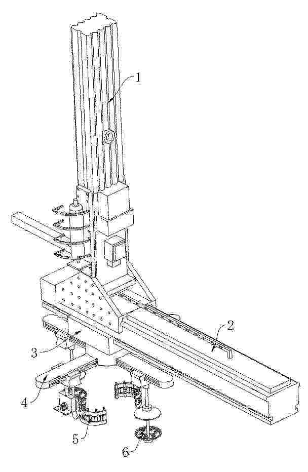
本发明公开了一种制氢用双极板加工翻转机械臂,本发明涉及机械臂技术领域。包括Y向模组,还包括:X向模组,所述X向模组设置在Y向模组的下方;滑动架,所述滑动架滑动连接在X向模组的外部;控制机构,所述控制机构包括第一滑动箱和第二滑动箱,所述第二滑动箱的内部设置有第二电机,所述第二滑动箱的底部设置有承接机构,所述第二电机用于驱动承接机构偏转;翻转机构,所述翻转机构包括第一电机,所述第一电机的外部设置有第一弧形架,所述第一弧形架的外部设置有第一接触组件,所述第一电机用于驱动第一弧形架与第一接触组件翻转至与双极板适配的角度。该制氢用双极板加工翻转机械臂,达到了提高设备的使用效率的目的。
Resumen de: CN121802458A
本发明公开了一种煤基碳材料负载氧化钌电催化剂及其制备方法与应用,属于电催化剂技术领域,以煤基炭材料与钌源为原料,通过离子吸附‑烧结法得到煤基碳材料负载氧化钌电催化剂;本发明利用煤基碳材料作为钌氧化物颗粒的载体,使钌氧化物颗粒均匀分散在煤基碳材料表面,使其更多的活性位点暴露在表面,并且钌氧化物在碳材料表面结合较紧密,从而提高了其在酸性条件下的OER性能和稳定性;本发明煤基碳材料负载氧化钌电催化剂的制备方法简单,煤基碳材料廉价丰富,极大地降低了OER催化剂的制备成本,有利于规模化生产,在目前的电解水制氢领域具有良好的应用前景。
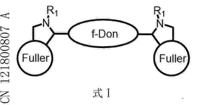
Resumen de: CN121800807A
0001 本发明公开了一种电子离域提高光催化产氢性能的富勒烯哑铃光催化剂。所述富勒烯哑铃光催化剂具有受体‑给体‑受体特征,为富勒烯‑噻吩稠环哑铃型结构,包含两个对称修饰的富勒烯碳笼,中间由稠环电子给体桥连,形状类似哑铃。所述富勒烯哑铃化合物具有式I所示结构特点。本发明催化剂制备工艺简单,设计规律性强。重要的是,该类哑铃分子光催化剂具有显著的电子离域性质,这使得光催化产氢性能得到了极大提升。本发明为高效光催化剂的设计和光催化产氢提供了有益指导。
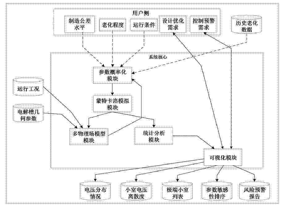
Resumen de: CN121809058A
本发明公开一种碱性电解槽性能离散性蒙特卡洛分析方法及系统,涉及电解制氢技术领域,包括:构建碱性电解槽的电化学‑热力学‑流体动力学多物理场耦合稳态模型;基于蒙特卡洛方法,对制造公差、老化效应及运行参数不确定性进行概率建模;通过大规模随机抽样模拟,量化碱性电解槽堆栈输出电压及碱性电解槽内部各电解小室电压的离散分布特征;识别高压“异常小室”及其对系统性能的影响;进行参数敏感性分析,识别高度敏感参数与低敏感参数。本发明可为碱性电解槽的稳健设计、健康监测、运维优化以及制造公差控制提供理论依据与方法支持。
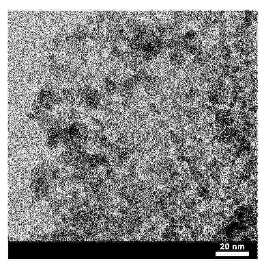
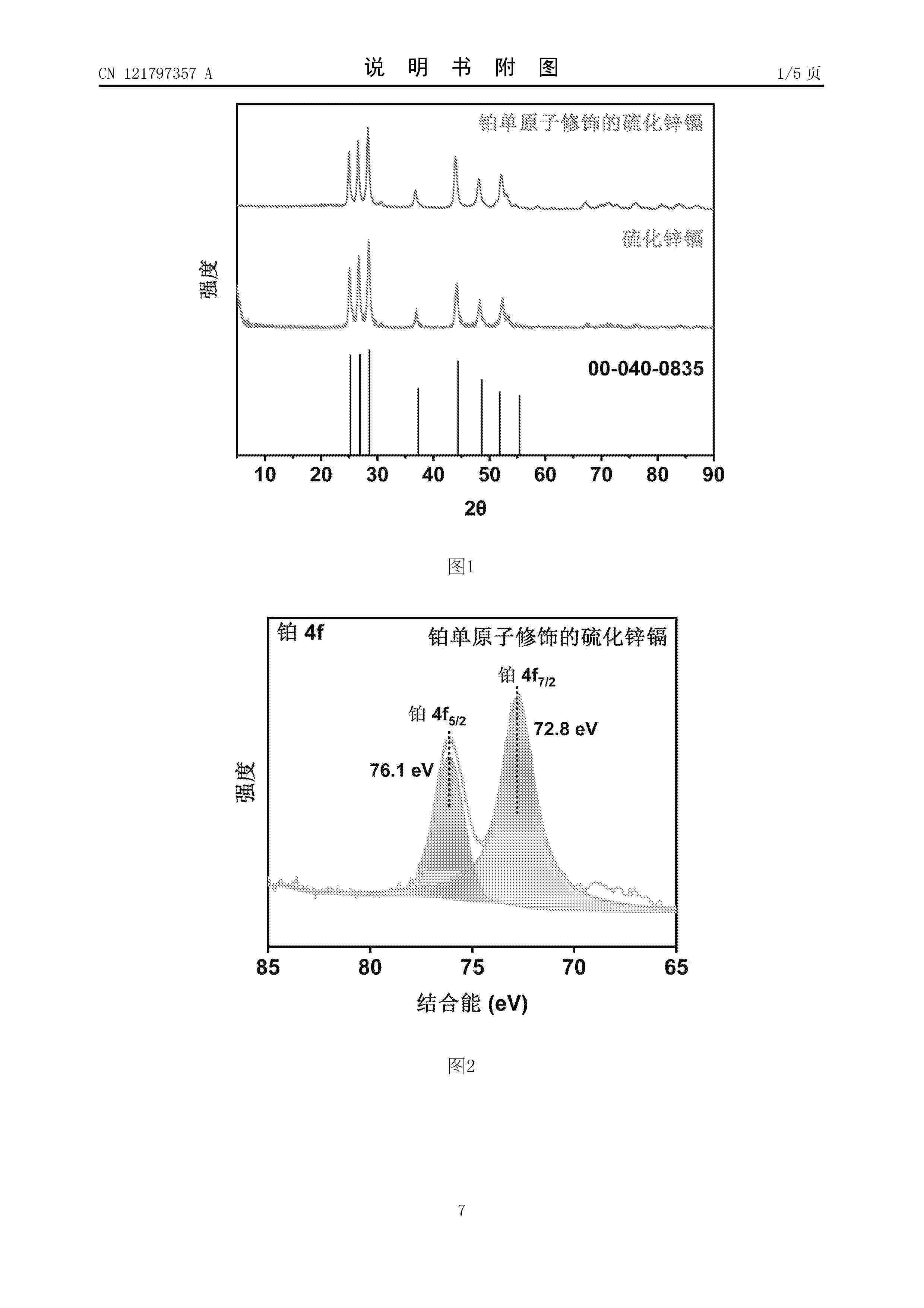
Resumen de: CN121797357A
0001 本发明属于光催化析氢技术领域,公开了一种铂单原子修饰的硫化锌镉催化剂的制备及其应用。针对能源危机下清洁能源的迫切需求,以及现有光催化析氢材料存在的效率不足、制备复杂、成本偏高等问题,本发明旨在提供一种工艺简便、成本可控且析氢性能优异的催化剂。其制备以醋酸锌、氯化镉、硫脲、聚乙烯吡咯烷酮、四氯铂酸钾和水合肼溶液为原料,通过水热合成法与光沉积技术结合,实现铂单原子在硫化锌镉表面的精准修饰与稳定负载。该催化剂在光催化析氢领域表现出优异的催化活性和长期稳定性,能显著提升析氢效率,为清洁能源开发提供高效解决方案,应用价值广泛。
Resumen de: WO2025041808A1
Provided is an electrode exhibiting high oxygen generating electrode catalytic activity as compared with conventional electrodes using manganese-based oxide as an oxygen generating electrode catalyst.
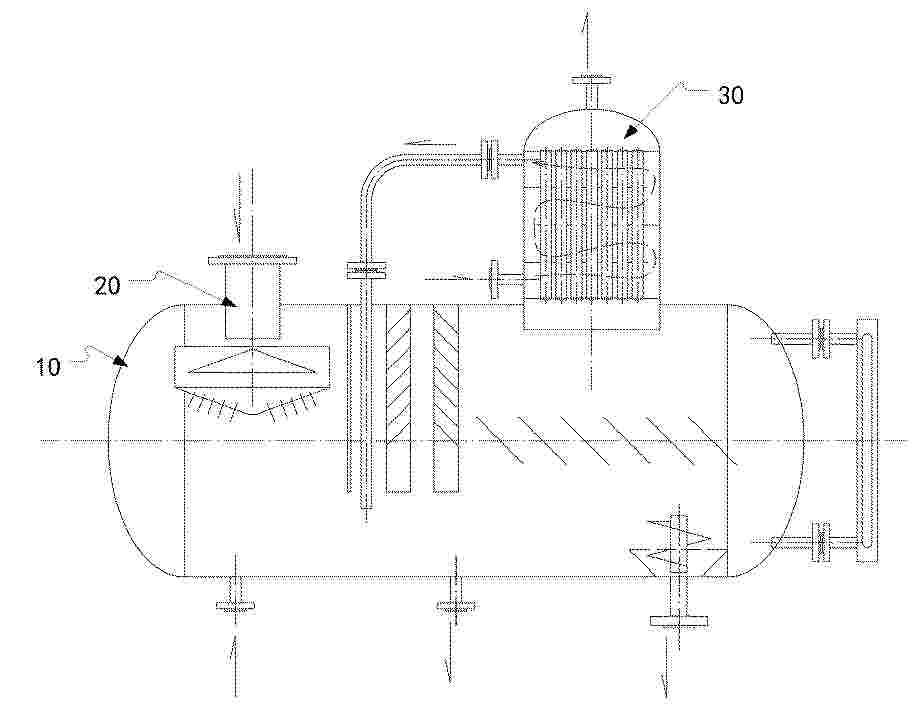
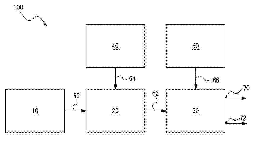
Resumen de: JP2025027342A
To provide a system for producing hydrogen gas and a method for producing hydrogen gas at low cost and with high purity, by collecting high-purity hydrogen gas at a high collection rate without using large-scale equipment.SOLUTION: A system 100 for producing hydrogen gas includes: a degassing device 20 for degassing raw water; an electrolysis device 30 for generating the hydrogen gas by electrolysis of the raw water deaerated by the degassing device 20; a pipe 62 connecting the degassing device 20 and the electrolysis device 30 and partitioning a flow channel through which the raw water is sent from the degassing device 20 to the electrolysis device 30; and a first oxygen gas supply device 40 for supplying oxygen gas to the degassing device 20 as a gas for deaeration.SELECTED DRAWING: Figure 1
Resumen de: EP1000000A1
The invention relates to an apparatus (1) for manufacturing green bricks from clay for the brick manufacturing industry, comprising a circulating conveyor (3) carrying mould containers combined to mould container parts (4), a reservoir (5) for clay arranged above the mould containers, means for carrying clay out of the reservoir (5) into the mould containers, means (9) for pressing and trimming clay in the mould containers, means (11) for supplying and placing take-off plates for the green bricks (13) and means for discharging green bricks released from the mould containers, characterized in that the apparatus further comprises means (22) for moving the mould container parts (4) filled with green bricks such that a protruding edge is formed on at least one side of the green bricks.
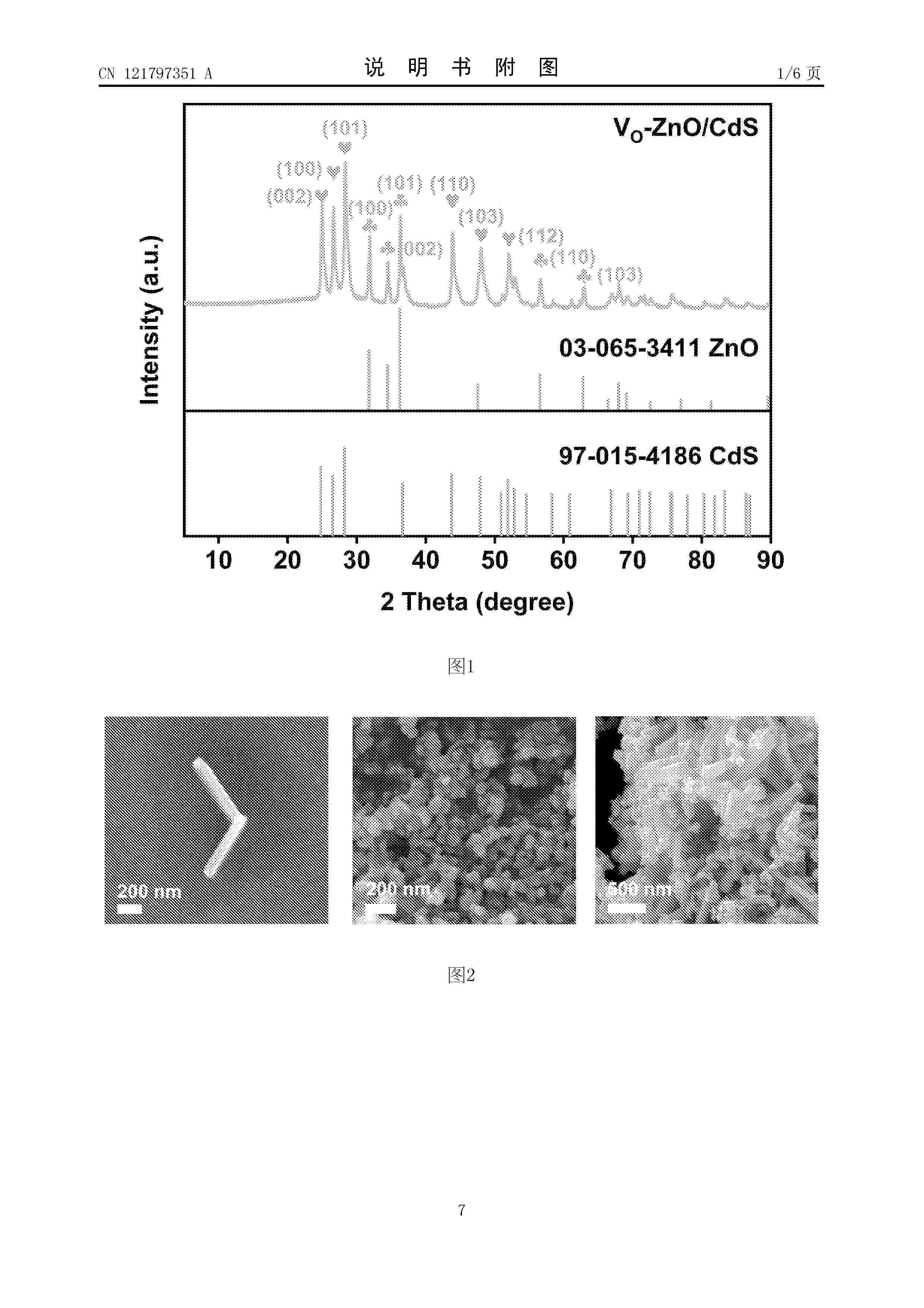
Resumen de: CN121797351A
0001 本发明涉及光催化析氢领域一种富氧空位氧化锌与硫化镉Ⅱ型异质结催化剂的制备及其应用。本发明的目的是提供一种制备工艺简便、成本低廉且具有高效光催化析氢性能的Ⅱ型异质结催化剂,以提升光催化析氢效率,缓解当前能源危机下对清洁能源的迫切需求。所采用的方法:以醋酸锌、氯化镉、硫脲、聚乙烯吡咯烷酮和硼氢化钠一同作为原料,采用水热合成方法,制备的一种富氧空位氧化锌与硫化镉Ⅱ型异质结催化剂可适用于光催化析氢领域且具有较高的催化活性和稳定性。
Nº publicación: CN121802470A 07/04/2026
Solicitante:
河南师范大学
Resumen de: CN121802470A
0001 本发明公开了一种葡萄糖酸修饰析氧电催化剂的制备方法及其在催化海水氧化中的应用,将泡沫镍置于(NH<4>)<6>Mo<7>O<24>·4H<2>O和一元强酸的去离子水中进行反应,再将反应后的泡沫镍置于含有葡萄糖酸亚铁的反应体系中制得析氧电催化剂。该氧析出电催化剂可以在海水氧化过程中通过葡萄糖酸配体在外亥姆霍兹层形成氢键,有效降低水合钾离子层的稳定性,使OH<–>顺利转移至内亥姆霍兹层;同时所形成的氢键网络有助于降低析氧反应过程的脱氢能垒,在一定程度上解决海水析氧反应效率低的技术问题;葡萄糖酸的还原作用可以对催化剂表面电荷进行修饰,解决了海水氧化反应选择性差的技术问题,对开发高选择性和活性的海水析氧电催化剂具有重要意义。
 BOPI
BOPI
 Sede Electrónica