Si deseas distinguir tus productos, servicios o ambos de los de otra empresa, es posible que necesites una marca o nombre comercial. Descubre qué son, en qué consiste su procedimiento de registro y qué implica.

Información sobre los plazos de presentación de solicitudes de transformación de marcas de la Unión Europea en marca nacional española. Más información


Si tienes un nuevo dispositivo, producto o procedimiento que resuelva un problema técnico o tenga una ventaja práctica, existen distintas formas de protegerlo en España y en otros países. Descubre cómo hacerlo.

¿Tu innovación reside en la estética, la ornamentación o la apariencia de tu producto? Protégela mediante un diseño industrial. Descubre qué derechos confiere el registro y cómo realizar la tramitación.

Las indicaciones geográficas protegen el nombre de un producto originario de una zona geográfica, a la cual le debe una determinada calidad, reputación u otra característica. Descubre qué son, en qué consiste su procedimiento de registro y qué beneficios conceden.

Las patentes publicadas en todo el mundo son una valiosa fuente de información científica, técnica y comercial.

Si eres emprendedor/a o una empresa y quieres potenciar y mejorar la rentabilidad de tu negocio protegiendo de forma adecuada los activos intangibles de tu organización, en este espacio encontrarás lo necesario.


 859
resultados
859
resultados
 Última actualización
04/05/2026 [07:11:00]
Última actualización
04/05/2026 [07:11:00]


 Resultados 125 a 150 de 859

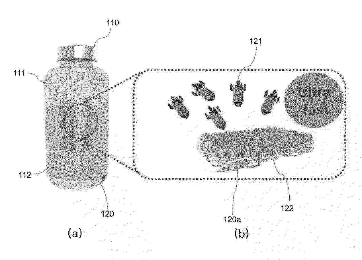
Resumen de: KR20260049358A
0001a 본 발명의 일 실시예는 3차원 입체 구조를 가지는 수전해 전극 및 케스터라이트계 박막 태양전지를 포함하는 태양전지-물분해 전기화학 시스템을 제공한다. 본 발명의 다른 실시예에 따른 태양전지를 이용한 물분해 전기화학 시스템은 수전해 전극과 케스터라이트(kersterite)계 물질을 광흡수층에 포함하는 케스터라이트계 박막 태양전지를 포함하여 예상 전압 1.6 V이고, 수소 변환 효율(STH, Solar to Hydrogen) 은 18%까지 달성하는 효과가 있다.

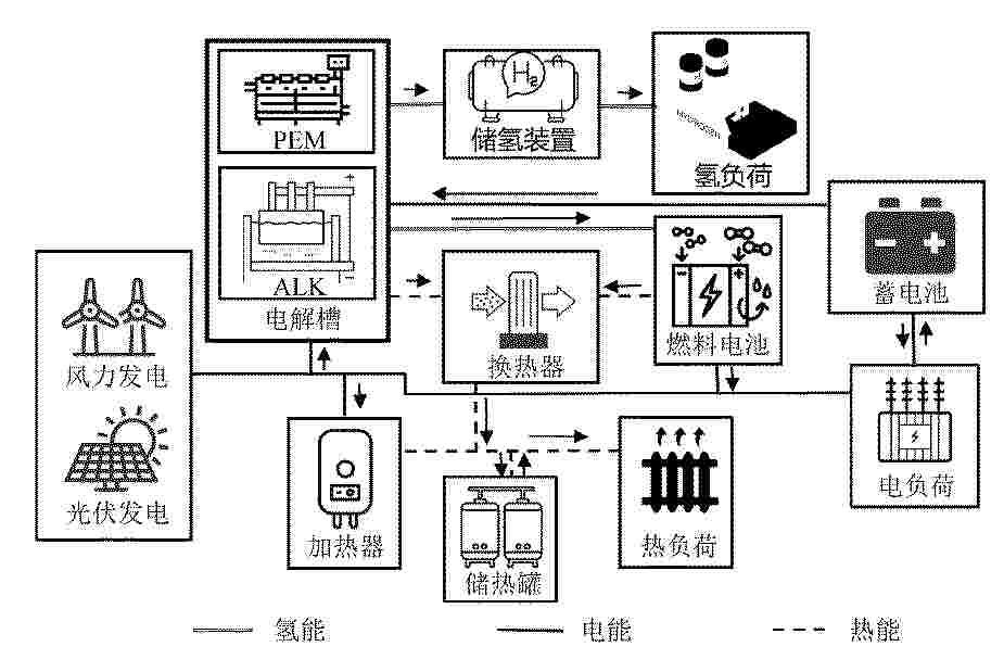
Resumen de: CN121853051A
本发明提供了一种考虑季节性风光波动的混合电解水制氢系统协同优化方法。该方法采用变分模态分解算法解析风光功率频谱,提取超高频、过渡频段和超低频三个本征模态函数分量;建立包含季节调度层、日内优化层和实时控制层的多时间尺度协同优化框架;将超低频分量分配至碱性电解槽,超高频分量分配至质子交换膜电解槽;构建电‑热‑寿命多场耦合的效能优化模型,实现效率最大化与寿命损耗、运行成本最小化的多目标优化;采用基于效率曲线二阶导数的设备投切临界点计算方法及梯度保护策略。本发明可以有效提升系统对季节性波动的适应性、运行经济性和设备寿命。
Resumen de: CN121852945A
本申请涉及一种双层气液解耦流道的低阻抗电解小室及电解槽装置,电解小室包括阴极反应电极、阳极反应电极以及置于两者之间的隔膜,在反应电极的两侧,分别设置了阴极侧多孔双极板和阳极侧多孔双极板,在每块多孔双极板的背离反应电极的一侧,通过机械加工形成一个下沉式的凹陷区域,所述阴极侧多孔双极板和阳极侧多孔双极板背离反应电极的一侧还设置有外侧主气体室,阴极侧多孔双极板和阳极侧多孔双极板上贯穿设置了孔隙。本申请显著提升气泡的排出效率,减少电解反应区域的欧姆电阻,从而大幅提升电解槽的综合性能和运行寿命。
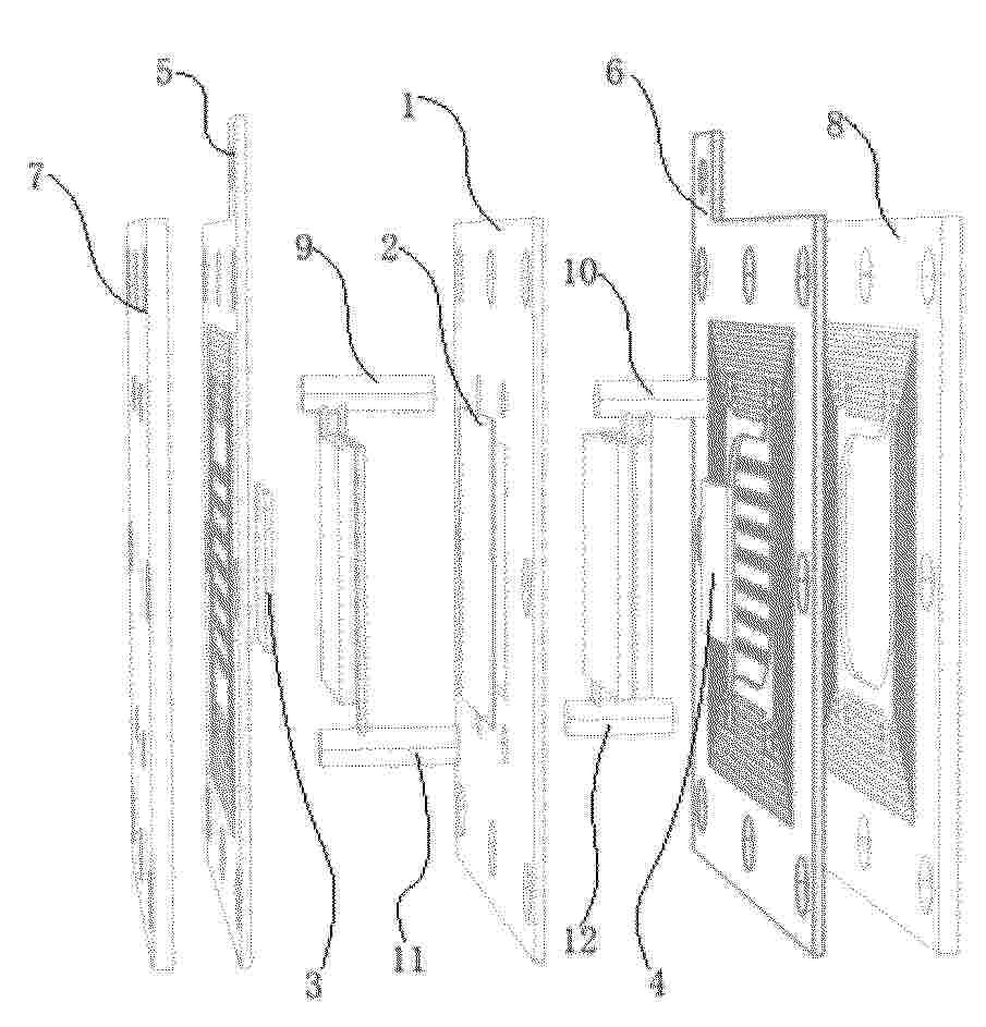
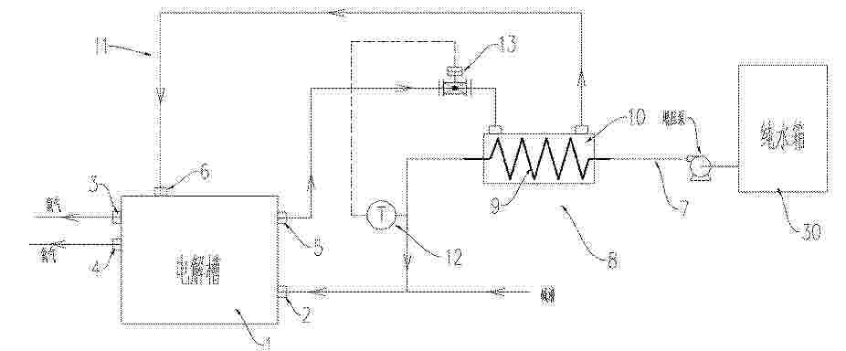
Resumen de: CN121852956A
0001 本发明公开了一种带余热利用的碱性电解水制氢系统,包括碱性电解槽、纯水供应装置、余热换热装置、温控组件及配套连接管路;所述余热换热装置串联于纯水箱与碱性电解槽之间的补水管路,其余热输入接口与碱性电解槽的余热输出端连通,余热输出接口与碱性电解槽的余热回流端连通,通过回收电解槽运行产生的余热对补给水进行预热;所述温控组件根据补水管路出水端的温度信号,动态调节余热载体的流量,使补给水进入电解槽时精准达到工艺要求温度。本发明实现了电解槽余热的高效回收利用,替代传统额外加热设备,降低系统运行能耗15%以上,且无需对现有电解槽主体结构进行大幅改造,改造成本低,适用性强,可广泛应用于工业级碱性电解水制氢场景。
Resumen de: CN121853010A
0001 本发明提供一种Ir/IrO<2>催化剂及其制备方法及其应用、膜电极。所述Ir/IrO<2>催化剂的制备方法包括以下步骤:将包括铱源和无机酸盐的混合物在固相下煅烧,得所述Ir/IrO<2>催化剂。将本发明的Ir/IrO<2>催化剂应用于酸性电解水析氧反应中,过电位较低、稳定性较高;将采用本发明的Ir/IrO<2>催化剂制得的膜电极应用于质子交换膜水电解催化反应中具有较高的活性和稳定性。
Resumen de: CN121853044A
本发明涉及有机无机复合材料制备及应用技术领域,具体是一种ZIFs/聚苯胺多级结构复合材料及其制备方法与应用。将一种金属化合物加入含表面活性剂的溶液中得到金属盐溶液A,将有机配体加入溶剂中得到有机配体溶液B,将金属盐溶液A和有机配体溶液B混合后搅拌反应,之后冷却、洗涤、干燥,得到基底金属ZIFs晶种,将其分散到溶剂中,超声得到悬浮液,将另一种金属化合物和有机配体加入悬浮液中,调整pH,水热反应,之后冷却、洗涤、干燥,得到多金属ZIFs材料,将上述材料加入到质子酸中,然后加入苯胺和氧化剂,在冰浴中搅拌聚合反应,同时聚苯胺与ZIFs上的金属位点发生强配位,即得复合材料。所得复合材料在电催化分解水析氧反应中具有优异的析氧性能。
Resumen de: CN121853037A
0001 金属氧化物与贵金属共同修饰NiFe氢氧化物催化剂及其制备方法和应用,它涉及析氧反应镍基电催化剂及其制法和应用。它是要解决现有的电解海水制氢催化剂的成本高、效率较低的技术问题。本催化剂是在泡沫镍表面原位生长微米级NiFe层状双氢氧化物,在NiFe层状双氢氧化物表面负载金属氧化物和贵金属,其中金属氧化物为氧化铬、氧化钼或氧化钒,贵金属为铂、锇、钌、铱、铑或钯。制法:将泡沫镍浸没于含Ni和Fe离子的溶液中电沉积后,再依次在金属酸、贵金属溶液中浸渍、干燥,得到催化剂。它在碱性海水中过电势205mV@10mA cm<‑2>,稳定性超1000h,可1000mA cm<‑2>的大电流下工作,可用于电解海水制氢。
Resumen de: CN121853032A
本发明涉及新能源领域,公开了一种金属异质结构电催化剂及其制备方法和应用,催化剂包括MoNi4和MoO2构成的异质结构,以及掺杂在MoNi4和MoO2中的金属元素,金属元素选自铁和/或锰;基于催化剂的总量,MoNi4的量为30‑40mol%,MoO2的量为40‑50mol%,金属元素的量为0.1‑0.5mol%。本发明提供的催化剂没有使用贵金属,成本低,更重要的是本发明提供的催化剂在碱性条件下具有优异的催化活性,在HER、OER和HMFOR反应中均具有较小的Tafel斜率值,反应动力学快,在电解水的过程中电荷传递电阻小,且具有较大的电化学表面积和双电层电容Cdl,电化学活性面积大,稳定性持久,恒定电解至少持续100h。
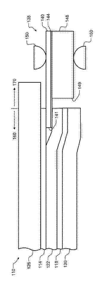
Resumen de: US20260103815A1
A water electrolysis cell includes a cathode electrode, an anode electrode, and a polymer electrolyte membrane arranged between the cathode electrode and the anode electrode. A porous transport layer is arranged adjacent to the anode electrode. A gas diffusion layer is arranged adjacent to the cathode electrode. The cathode electrode, the anode electrode, and the polymer electrolyte membrane overlap in an active region. A barrier assembly includes a barrier layer including an inner edge defining an inner cavity and an outer edge. The inner edge of the barrier layer overlaps and is bonded by an adhesive to a first side of the polymer electrolyte membrane in the active region. The outer edge of the barrier layer surrounds the active region and extends into an inactive region.
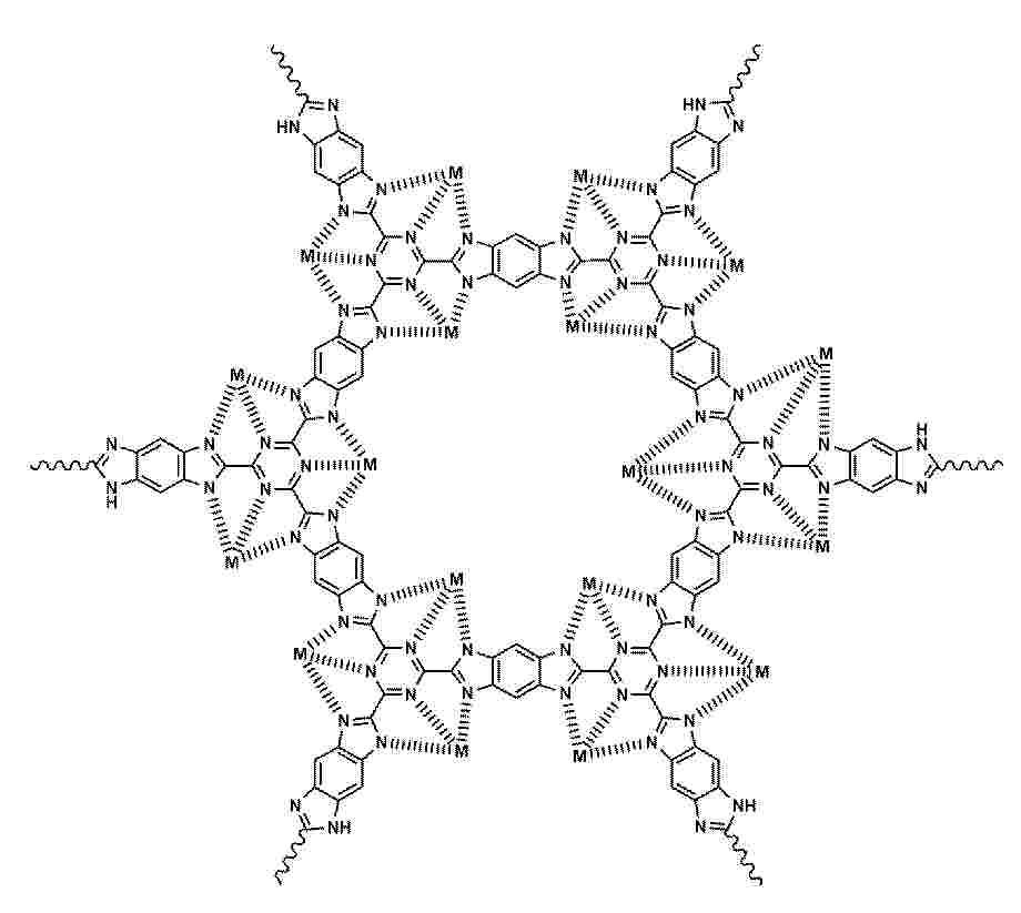
Resumen de: CN121852989A
0001 本发明公开了一种基于共价有机框架的非贵金属单原子催化剂及其制备方法与在电催化析氧反应中的应用,属于电催化材料技术领域。该催化剂包括共价有机框架以及与所述共价有机框架以配位键连接的单原子形式的非贵金属原子,该催化剂具有如式(I)所示的重复结构单元。本发明构筑了具备独特三齿氮配位结构的苯并双咪唑‑三嗪共价有机框架,能稳定锚定多种非贵金属单原子,形成结构高度均一且明确的活性中心,从根本上解决了传统催化剂活性位点不均一与稳定性差的问题。本发明的催化剂在碱性析氧反应中展现出媲美贵金属催化剂的高活性与高稳定性,为解决析氧催化剂成本与性能的矛盾提供了一类新的材料体系。
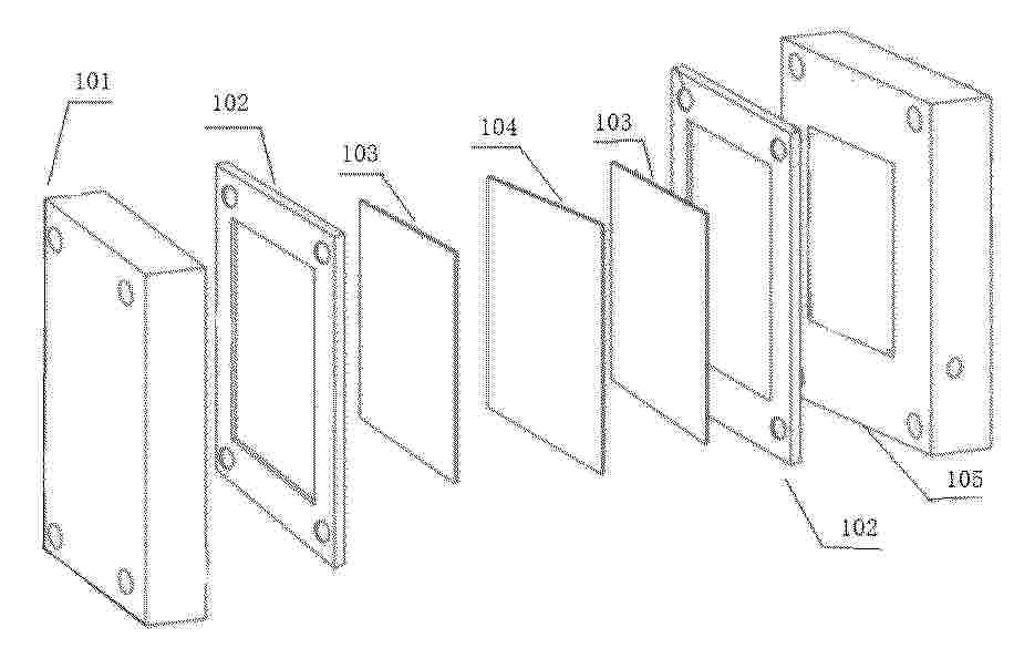
Resumen de: CN121852947A
0001 本发明公开了一种增强扩散型流道结构的新型PEM电解槽,包括电解室结构,电解室结构依次由阴极板、阴极扩散层、膜电极、阳极扩散层、阳极板组成并通过紧固件进行固定,阳极板和阴极板相邻一侧表面均设有突出结构,以形成流道组。该新型PEM电解槽通过在阳极板和阴极板内侧设置“突出结构”构成流道组,使电解液在流道中形成定向流动路径,有效引导电解液分布至整个催化区域,避免局部干涸或浓差极化。流道结构为生成的氢气(阴极)和氧气(阳极)提供明确的逸出通道,减少气泡在催化剂表面驻留时间,降低欧姆阻抗和过电位。采用紧固件连接各功能层,便于组装、拆卸与维护,适用于大规模堆叠式PEM电解槽系统。
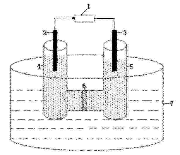
Resumen de: CN121852942A
本申请属于化学品制备技术领域,具体涉及一种用于制氘的装置、方法及铁镍双金属催化剂的制备方法。本申请提供的一种用于制氘的方法,以KOD/MeOD溶液为阳极电解液,利用质子交换膜、电解池、催化剂直接电解氘代甲醇生产氘代甲酸,氘代甲醇可以在阳极电解池的混合液中直接被氧化为氘代甲酸,在阴极侧析出氘气,实现选择性氧化低碳分子解耦电解重水制氘;并根据制氘方法设计了制氘的装置,包括电源、阳极、阴极、阳极电解池、阴极电解池、质子交换膜和恒温外壳;所述催化剂选择铁镍双金属催化剂NiFe2O4/NF,本申请实施例提供了该催化剂的制备方法,铁镍双金属催化剂NiFe2O4/NF具有高性能、稳定的优点。
Resumen de: CN121853057A
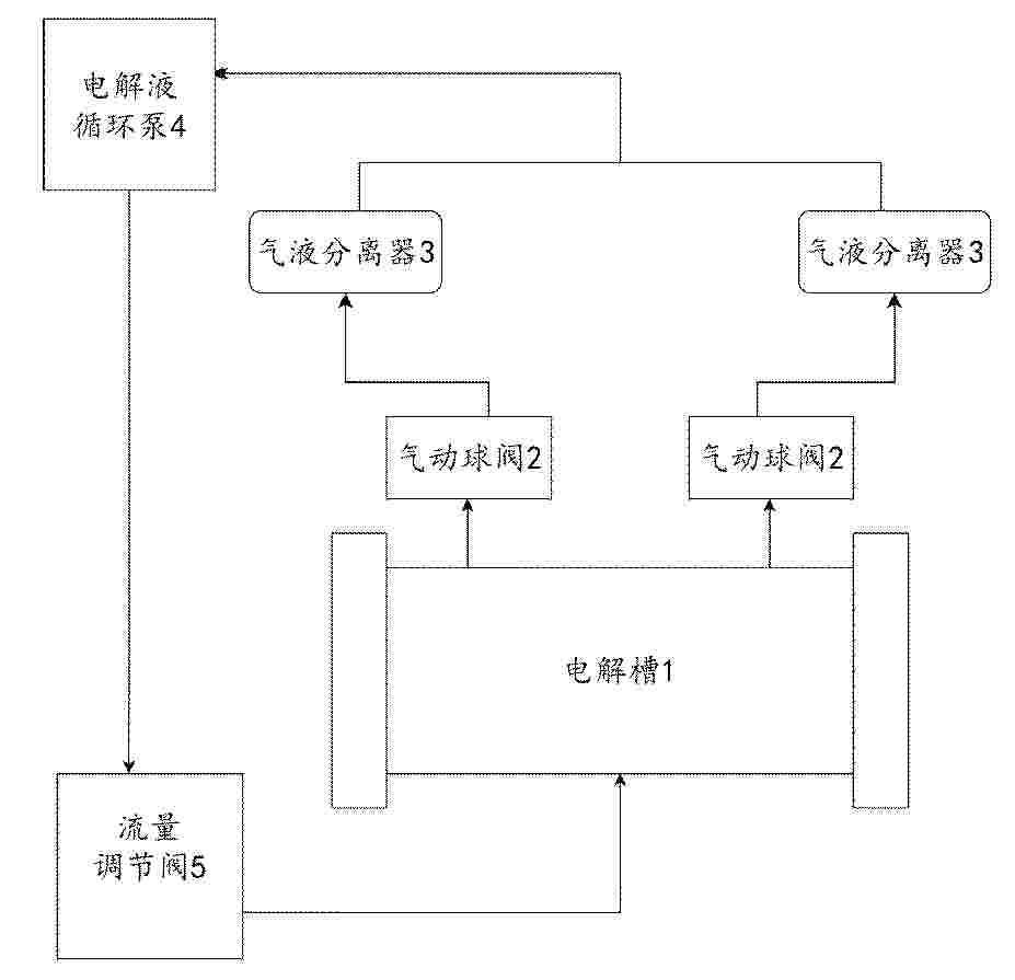
本发明公开了一种电解制氢的电解液流量控制装置、方法、设备和存储介质。属于能源和自动化控制技术领域。装置包括电解槽、气动球阀、气液分离器、电解液循环泵和流量调节阀通过电解液管路连接形成回路;电解槽电解电解液得到气液混合物并输送至气液分离器,以使其将气液混合物分离成气体和电解液,并回收电解液;电解液循环泵将分离后的电解液输送回电解槽;气动球阀控制气液混合物的输出;流量调节阀控制流量大小;控制器获取电解液流量、电解槽温度、电解液浓度和电解电流中至少一种参数;预测未来流量以控制电解槽电流、电解液循环泵和流量调节阀中至少一种,来调节流量大小。通过预测流量并精准控制,应对流量波动,保障电解槽稳定运行。
Resumen de: CN121853034A
本发明涉及一种无定型IrLa球形氧化物催化剂的制备方法及应用,所述制备方法包括以下步骤:S1、将铱盐、镧盐溶于水中,得到前驱体盐溶液;S2、向所述前驱体盐溶液中加入还原剂,在100‑220℃条件下进行水热反应,分离固体,得到中间体材料;所述还原剂选自柠檬酸、柠檬酸盐中的一种或多种;S3、将所述中间体材料在有氧环境下进行加热处理,加热产物经酸洗、烘干得到所述无定型IrLa球形氧化物催化剂。上述制备方法操作简单、可控,重复性好,且由上述制备方法制备得到的无定型IrLa球形氧化物催化剂由纳米颗粒组成,均匀度高、组成颗粒尺寸小、表面连续性好且无团聚现象,同时具备表现出优异的酸性OER催化性能和稳定性,在电解水制氢方面具有良好的应用前景。
Resumen de: CN121852996A
本发明涉及电催化技术领域,具体涉及一种RuMOx自支撑电催化材料及其制备方法和应用。为构建一种高效耐用的掺杂型Ru基电催化剂,本发明结合RuO2与碳布的优点,将亲水碳布放于含Ru盐和金属盐的混合溶液中,并通过热吸附及退火制备出在碳布上生长的RuMOx自支撑电催化材料,该材料表现出优异的电催化析氧活性。该方法不仅显著提高了Ru基电催化剂的催化性能,而且简化了制备流程,适合大规模工业化应用。
Resumen de: CN121853060A
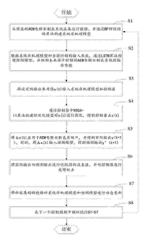
0001 本发明提供一种基于数据驱动模型预测控制的阴离子交换膜电解水制氢控制方法及系统,包括:采集运行数据,并通过BP神经网络算法构建系统非机理模型;根据系统非机理模型预测AEM电解水制氢系统的输出参数;将输出参考值y(t)输入系统非机理模型和控制器;通过NSGA‑II算法构建的优化模型对x(t)进行优化;将Δx(t)应用于AEM电解水制氢系统中,并得到实际输出和预测输出;进行比较得到误差值,并对控制器进行反馈校正;对系统非机理模型和预测模型进行更新。本发明对系统非机理模型和预测模型进行动态更新,能实时反映AEM电解水制氢系统的动态变化,并对控制模型进行动态更新,有效提高控制模型的精度。
Resumen de: CN121853012A
0001 本发明公开了一种银负载和阴离子穿插的层状催化剂及其制备方法与应用,先采用水热法在泡沫镍上生长草酸根离子穿插的层状钴铁双金属氢氧化物CoFe‑C<2>O<4>2– ‑LDH,然后将其浸泡于AgNO<3>的水溶液,反应生成银负载的草酸根离子穿插的层状钴铁双金属氢氧化物Ag/CoFe‑C<2>O<4>2– ‑LDH。该银负载和阴离子穿插的层状氢氧化物在电解海水析氧反应中具有优异的催化活性和稳定性。在施加电压下,Ag纳米颗粒在海水析氧过程中原位生成AgCl,可固定氯离子,并与嵌入到CoFe层状双氢氧化物中具有高负电性的C<2>O<4>2– 阴离子基团协同构建抗氯离子侵蚀屏障,从而增强NiFe层状双氢氧化物在海水电解中的抗氯腐蚀性。
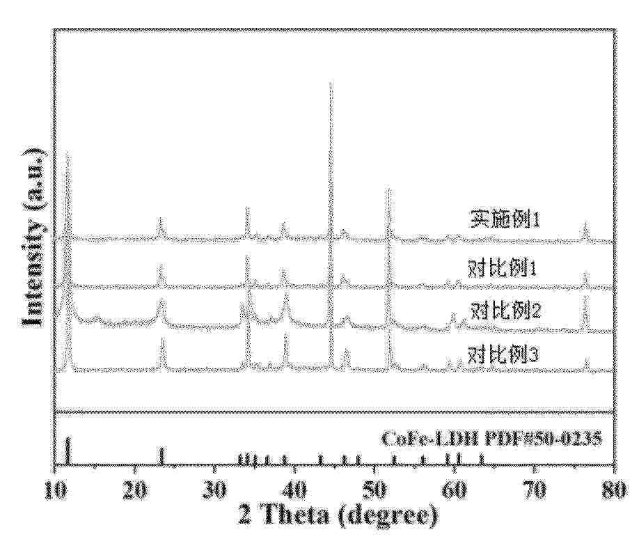
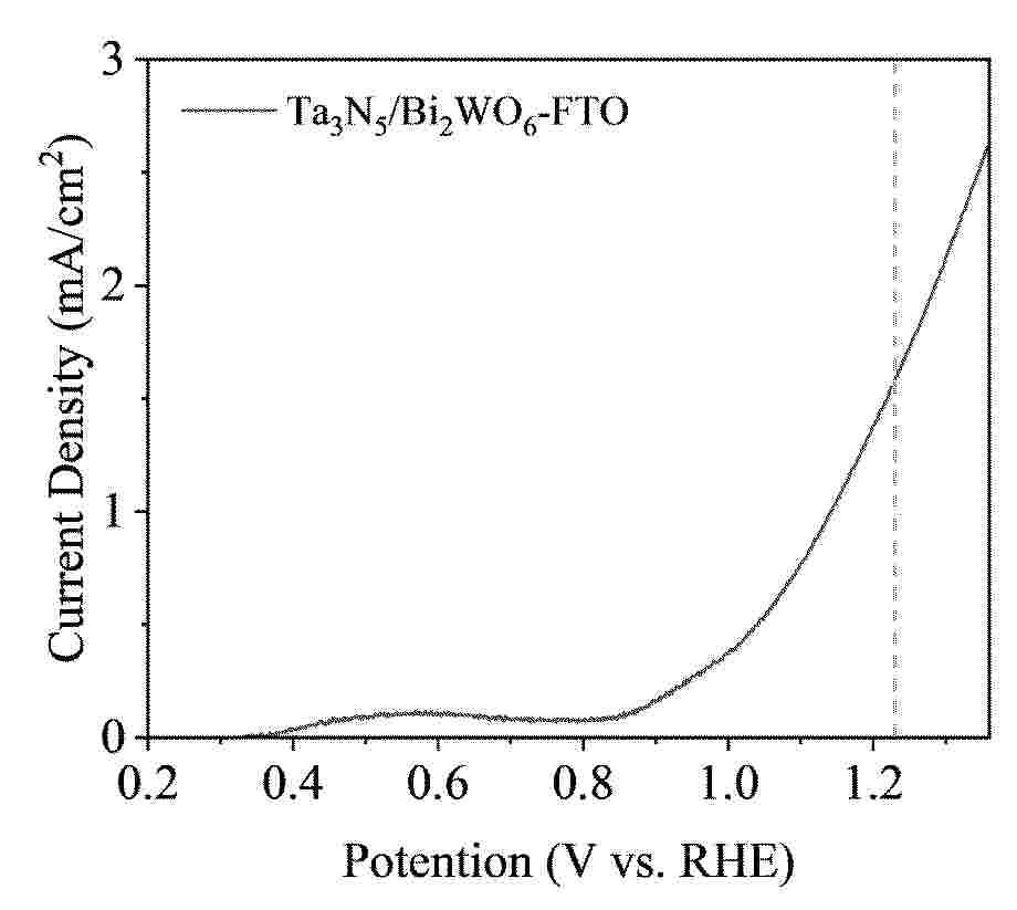
Resumen de: CN121853013A
0001 本发明公开了一种Z型异质结Ta<3>N<5>/Bi<2>WO<6>‑FTO光电极材料及其制备方法和应用,制备方法包括:分别制备Bi<2>WO<6>粉体和Ta<3>N<5>粉体;将Bi<2>WO<6>粉体和Ta<3>N<5>粉体分散在异丙醇中形成前驱体溶液,使用提拉镀膜机,将预处理后的FTO基片垂直浸入前驱体溶液中,静置数秒后以恒定速度1‑3 mm/s匀速提拉,使基片表面形成均匀的湿膜;将负载有湿膜的玻璃片立即转移至预热的热台上,在空气气氛中60℃热处理5‑10 min;最后,将制备好的薄膜置于管式炉中,在氩气作为保护气体气氛下400‑500℃下进行退火处理1‑2 h,最终得到Ta<3>N<5>/Bi<2>WO<6>‑FTO光电极材料;本发明制备的Ta<3>N<5>/Bi<2>WO<6>异质结具有宽光谱响应能力、高效的光生电荷分离与迁移能力、良好的结构稳定性,结合FTO导电基底提升光电转换效率,使该光电极材料表现出优异的光电催化活性。
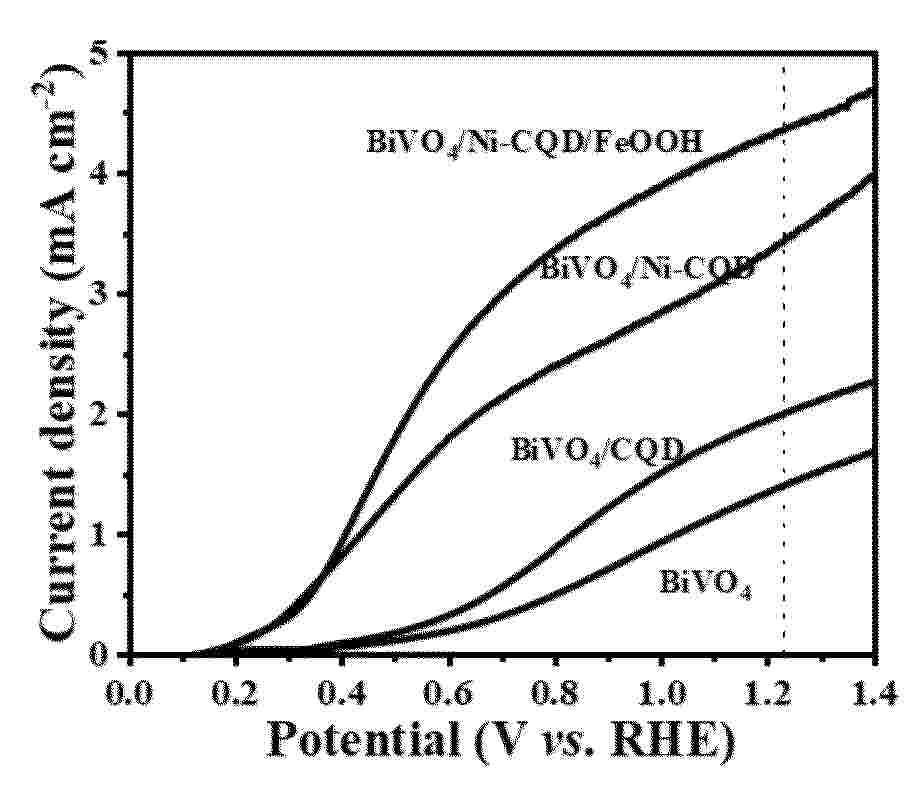
Resumen de: CN121852999A
本发明公开了一种掺杂碳量子点改性光电催化光阳极的制备方法,包括如下步骤:a.将柠檬酸水溶液在高压水热反应釜中加热,冷却后经透析、冷冻干燥制得碳量子点粉末;b.将所述步骤a制得的碳量子点粉末溶于去离子水中得到溶液,向所述溶液中加入钒酸铋浸泡,经洗涤、干燥后制得掺杂碳量子点改性光电催化光阳极。本发明制得的光阳极材料,不仅能够加速电荷的转移和分离,还能够有效抑制空穴的复合,使材料表现出较高的光电流密度,同时材料具有优异的电化学氧化催化活性,有效提高了光阳极的水氧化反应动力学,提高了电极材料的稳定性。
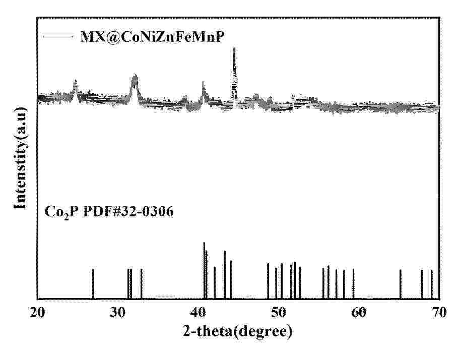
Resumen de: CN121853015A
本发明公开了一种MXene@高熵金属磷化物复合电极材料及其制备方法和应用,以三维多孔基底为骨架,三维多孔基底上负载有MXene,MXene表面负载有五元高熵金属磷化物CoNiZnFeMnP;其中,所述MXene为Ti3C2Tx,由Ti₃AlC₂ MAX相通过刻蚀去除层间的Al原子,并引入表面官能团Tx制得。本发明所制备的MX@CoNiZnFeMnP具备较大的比表面积、大量的活性位点以及丰富的异质界面,该复合电极材料具有独特的多级花状分级结构、显著的高熵效应及强界面耦合作用,展现出极高的催化活性、优异的电荷传输能力及工业级的长期稳定性,能够作为一种高效的双功能电催化剂,广泛应用于电解水过程中的析氢、析氧及全水解反应。同时,本发明制备方法兼具简便、价廉及易于规模化的优势,有效克服了背景技术中的瓶颈,为发展高性能双功能电催化剂提供了新思路。
Resumen de: CN121847034A
本发明属于等离子体催化氨分解制氢技术领域,具体公开了一种螺旋电极的单程多程循环模式制氢系统和方法,包括螺旋地电极等离子体催化膜反应器、气体循环模式切换单元和中央控制系统,所述螺旋地电极等离子体催化膜反应器采用同轴多层套管结构,所述螺旋地电极等离子体催化膜反应器包括自外向内设置的承压绝缘单元、介质阻挡放电等离子体活化单元和催化分离复合内芯单元。本发明采用上述一种螺旋电极的单程多程循环模式制氢系统和方法,不仅能在单程模式下实现高效制氢,更能在多程模式下通过气体多次循环利用,在相同运行时间内大幅减少原料消耗、提升能效,提升其经济性、可持续性。
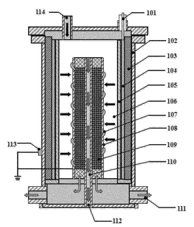
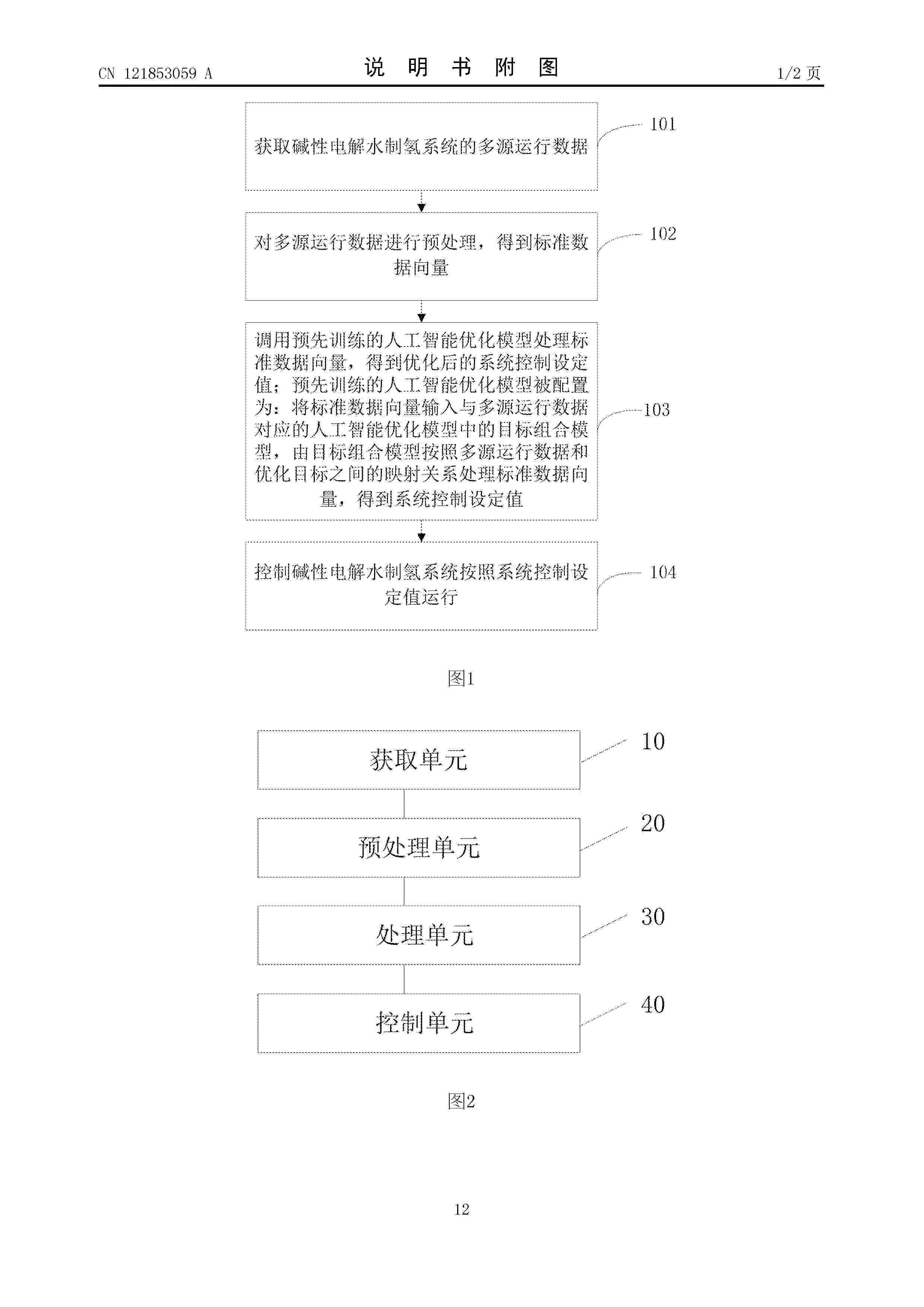
Resumen de: CN121853059A
0001 本申请公开了一种碱性电解水制氢系统的控制方法及相关装置,涉及电解水制氢技术领域,获取碱性电解水制氢系统的多源运行数据后进行预处理,得到标准向量数据,然后,调用预先训练好的人工智能优化模型处理标准数据向量,该模型中采用与多源运行数据对应的目标组合模型处理标准数据向量,按照多源运行数据和优化目标之间的映射关系优化各标准数据向量,得到系统控制设定值,最后控制系统按照系统控制设定值运行。本申请中采用预先训练好的人工智能优化模型计算得到多源运行数据对应的优化后的系统控制设定值,能够同时调整系统中不同执行机构的运行数据,进一步能够适应各执行机构在不同工况下的动态变化,提高系统在变工况下的效率。
Resumen de: CN121853040A
本发明公开了一种用于增强电催化析氢性能的二硫化钼纳米纤维材料的制备方法。采用静电纺丝法配合热处理工艺方便的制备了二硫化钼纳米纤维,并且聚合物基体有效封装二硫化钼晶体可以提高二硫化钼催化剂的稳定性。二硫化钼纳米纤维由于纤维形貌赋予的导电网络、大的比表面积以及稳定结构,不论是在酸性环境还是在碱性环境中,都有良好的催化活性。在酸性条件下的过电位为202mV、塔菲尔斜率为93mV·dec‑1,碱性条件下的过电位为180mV、塔菲尔斜率为83mV·dec‑1。此外,MoS2纳米纤维在酸性和碱性条件下连续工作20h的稳定性优于Pt/C在同等条件下连续工作10h,这有利于它今后在工业中的实际应用。
Resumen de: CN121852988A
本发明具体涉及一种双片型镍铁层状双氢氧化物自支撑电极的制备方法及其应用,属于电解水制氢技术领域。所述方法以镍网为基底,采用氯化物前驱体与尿素为原料,在常压下通过共沉淀反应,于80‑90℃使双片型NiFe LDH原位生长于镍网表面。所得电极为自支撑结构,无需粘结剂,催化层由成对纳米片组成,单片厚度为5‑30 nm。该电极在30%KOH、90℃的模拟工业条件下,于5 A·cm‑2电流密度时析氧过电位较未处理镍网降低至少180 mV,并可稳定运行超过1000小时,表现出优异的高活性与长寿命特性。同时,该电极具有良好的抗电流波动能力,适用于海水电解及波动性可再生能源驱动的制氢系统,为低成本、高效率的工业电解水制氢提供了关键电极材料。
Nº publicación: CN121853052A 14/04/2026
Solicitante:
北京航天石化技术装备工程有限公司北京航天动力研究所
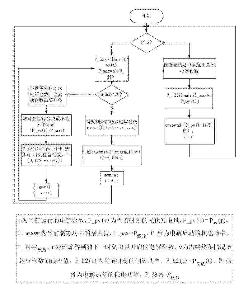
Resumen de: CN121853052A
0001 本发明公开了一种MW级离网光伏制氢系统电解自适应调节方法。本发明运用动态规划算法开发的电解自适应控制,可根据当前光伏发电量合理匹配制氢系统的预热、运行及热备情况,提高光伏利用效率与制氢产量。相比电解装置统一控制,本发明分组控制方式实现了制氢工况与光伏发电的跟随,提高了电解装置的波动适应性。
 BOPI
BOPI
 Sede Electrónica