Si deseas distinguir tus productos, servicios o ambos de los de otra empresa, es posible que necesites una marca o nombre comercial. Descubre qué son, en qué consiste su procedimiento de registro y qué implica.

Información sobre los plazos de presentación de solicitudes de transformación de marcas de la Unión Europea en marca nacional española. Más información


Si tienes un nuevo dispositivo, producto o procedimiento que resuelva un problema técnico o tenga una ventaja práctica, existen distintas formas de protegerlo en España y en otros países. Descubre cómo hacerlo.

¿Tu innovación reside en la estética, la ornamentación o la apariencia de tu producto? Protégela mediante un diseño industrial. Descubre qué derechos confiere el registro y cómo realizar la tramitación.

Las indicaciones geográficas protegen el nombre de un producto originario de una zona geográfica, a la cual le debe una determinada calidad, reputación u otra característica. Descubre qué son, en qué consiste su procedimiento de registro y qué beneficios conceden.

Las patentes publicadas en todo el mundo son una valiosa fuente de información científica, técnica y comercial.

Si eres emprendedor/a o una empresa y quieres potenciar y mejorar la rentabilidad de tu negocio protegiendo de forma adecuada los activos intangibles de tu organización, en este espacio encontrarás lo necesario.


 139
resultados
139
resultados
 Última actualización
02/05/2026 [07:22:00]
Última actualización
02/05/2026 [07:22:00]


 Resultados 125 a 139 de 139
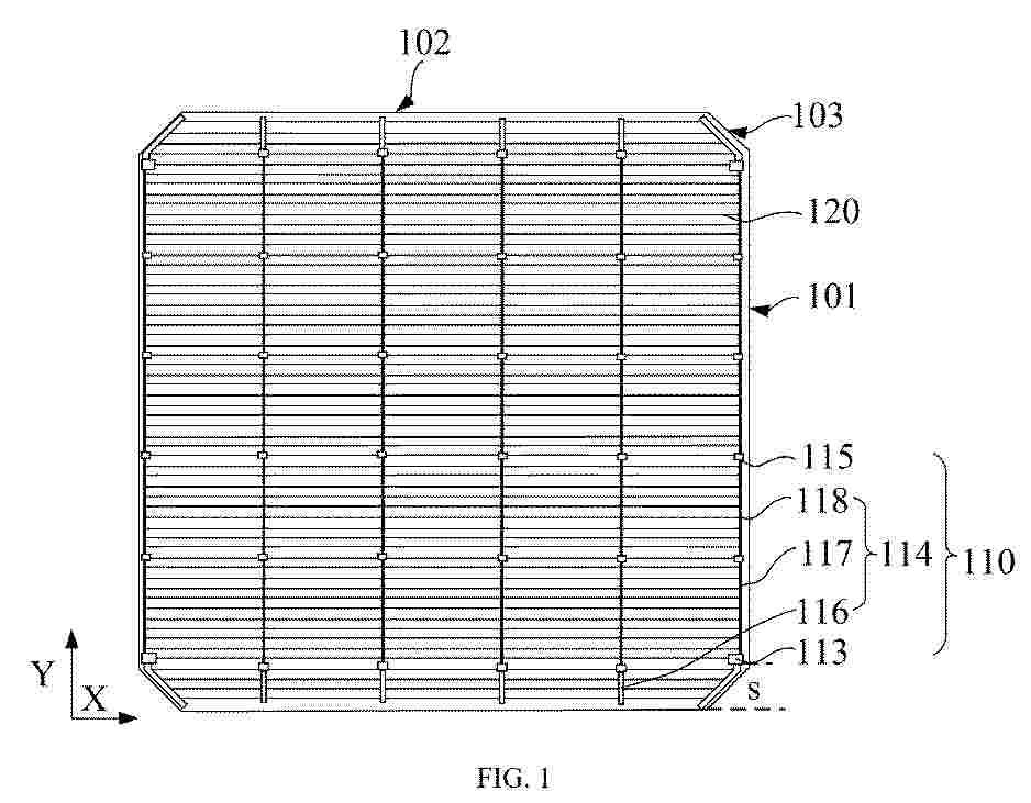
Resumen de: EP4730963A2
The disclosure relates to the photovoltaic field, and more specifically to a solar cell and a photovoltaic module. The solar cell includes a cell base and a plurality of main electrodes disposed on the cell base. The cell base has first edges and second edges, where the first edges include two opposite edges of the cell base along a second direction and the second edges include two opposite edges of the cell base along a first direction. The plurality of main electrodes extend in the second direction and are arranged at intervals in the first direction. The plurality of main electrodes include two first main electrodes, a respective first main electrode of the two first main electrodes is close to a corresponding first edge and includes two first connection pads respectively close to the second edges and a first connection wire electrically connected to the two first connection pads. The first connection wire has a first part between a respective first connection pad and a second edge adjacent to the respective first connection pad, and a second part between the two first connection pads. The first part has a first width, the second part has a second width, and the first width is greater than the second width. According to the solar cell, it is possible to at least improve the photoelectric conversion efficiency of the solar cell

Resumen de: WO2024256444A2
The present invention relates to a photovoltaic module having a protective back layer element that comprises a polypropylene composition comprising low levels of one or more white pigments, as well as to the use of titanium dioxide for maintaining elongation at break after UV treatment.
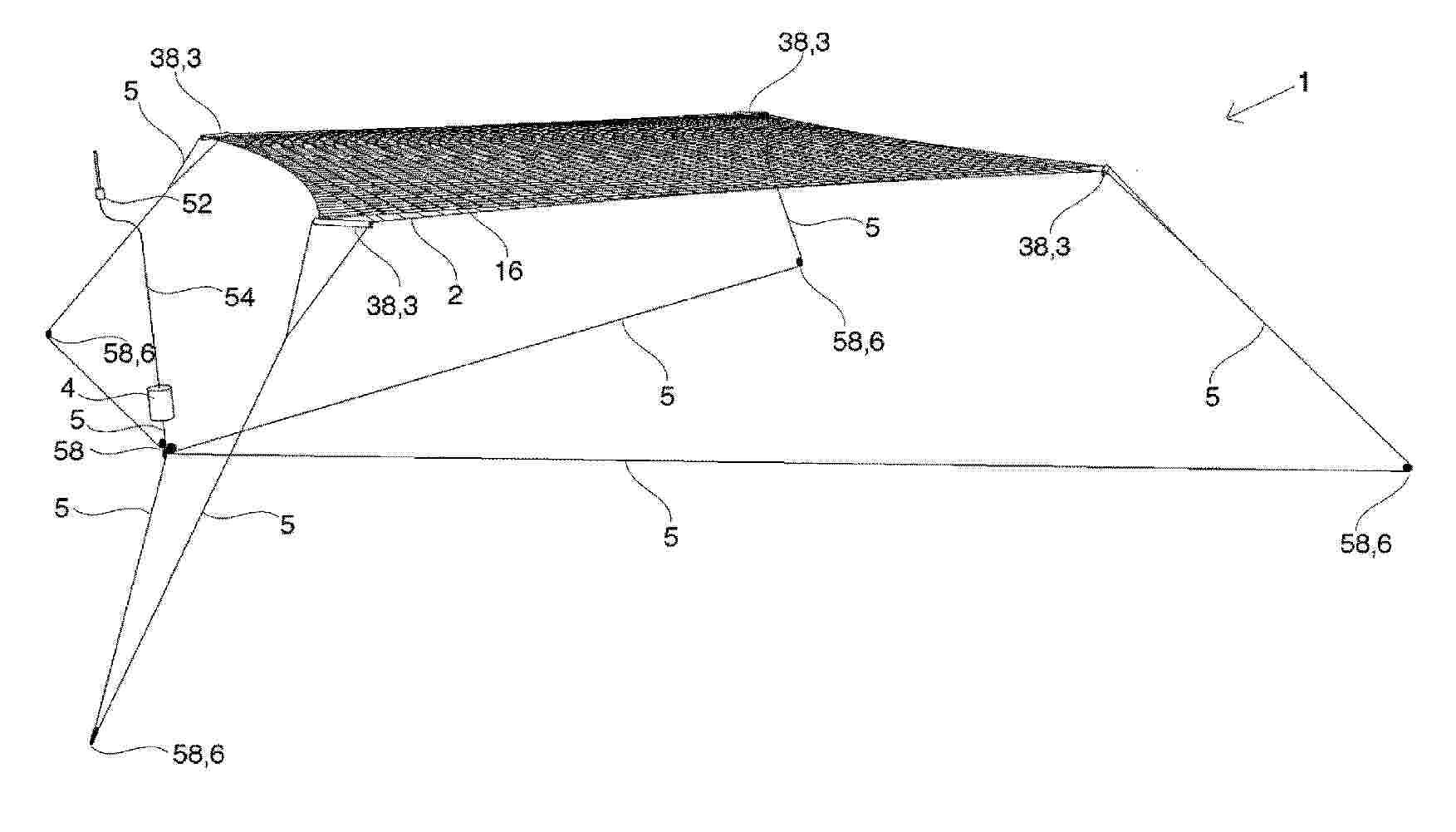
Resumen de: WO2024256529A1
The invention relates to a submersible solar installation comprising: a solar panel; at least one buoyancy element connected to the solar panel; wherein the solar panel and the at least one buoyancy element have a positive buoyancy at a water surface of a body of water; and a submersion means, which is adapted to apply a negative buoyancy force to the submersible solar installation; wherein the at least one buoyancy element has a reversibly compressible first buoyancy element. The invention also relates to a use of the submersible solar installation for generating electrical energy, to a transport system for a submersible solar installation, and to a use of the transport system.
Resumen de: WO2024256443A1
The present invention relates to a photovoltaic module having a protective back layer element that comprises a polypropylene composition comprising a certain combination of hindered amine light stabilizers and UV stabilizers, as well as to the use of the certain blend of hindered amine light stabilizers and UV stabilizers for maintaining elongation at break after UV or oven treatment.
Resumen de: WO2024256495A2
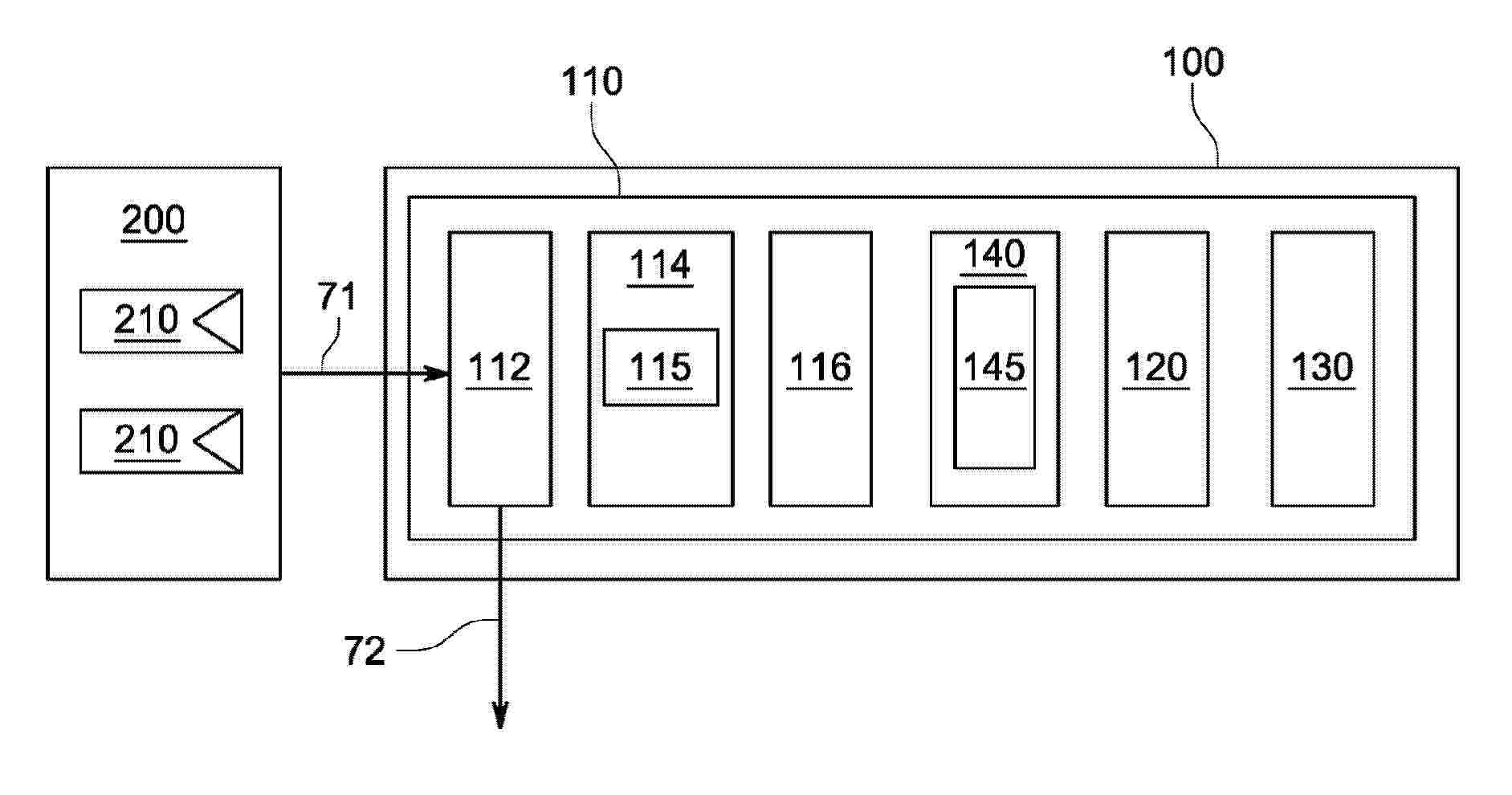
The invention relates to a method and a device for detecting an arc in a photovoltaic system (200). The method has the steps of: detecting (S100) the time curve of amplitude values of an electric variable of an electric current from the photovoltaic system, PV system (200); determining (S300) at least one value of a permutation entropy, PE, on the basis of the time curve of the amplitude values; determining (S400) at least one value of a Jensen-Shannon complexity, JSK, on the basis of the time curve of the amplitude values; and detecting (S500) whether an arc has actually occurred in the PV system (200) on the basis of the at least one determined value of the permutation entropy, PE, and on the basis of the at least one determined value of the Jensen-Shannon complexity, JSK.
Resumen de: WO2024256387A1
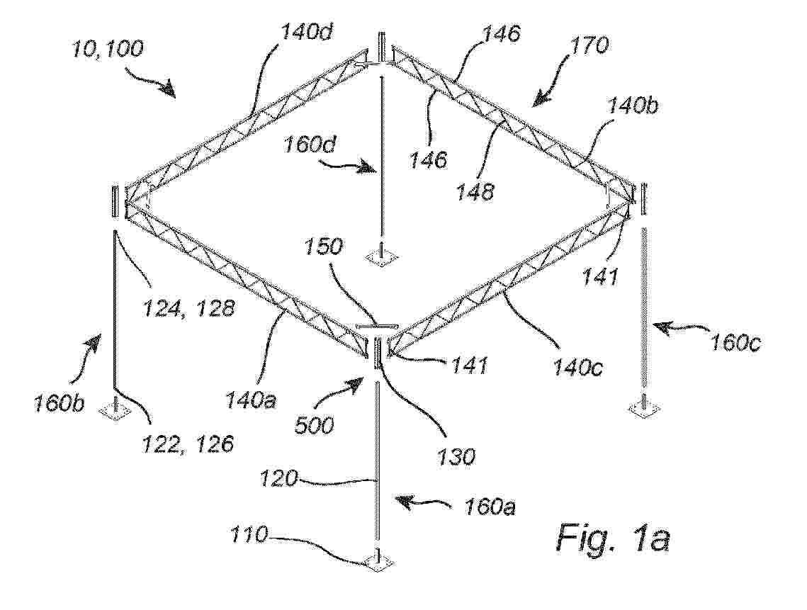
A modular solar panel support system (10) comprising: at least two base members (110) arranged to be supported by a ground surface, wherein each base member (110) comprises a base plate (112) and a base post (114) extending in an orthogonal direction relative to the surface of the base plate (112), each base post (114) having a first outer circumference (116); at least two elongate uprights (120), each upright (120) comprising a first tubular end portion (122) having a first inner circumference (126) and a second end portion (124) having a second outer circumference (128), wherein the first inner circumference (126) is larger than the first outer circumference (116); at least two tubular top members (130), each top member (130) having a second inner circumference (138) larger than the second outer circumference (128), and wherein an outer surface of each top member (130) comprises a fastening arrangement (132); and at least one truss beam (140) having two end portions, each end portion comprising a connecting arrangement (142) for securing the respective end portion of the truss beam (140) to the fastening arrangement (132) of a respective top member (130). Each base post (114) is arranged to be inserted into the first tubular end portion (122) of a respective upright (120), and wherein the second end portion (124) of each upright (120) is arranged to be inserted into a respective top member (130).
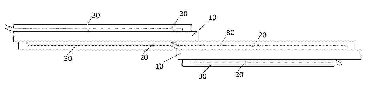
Resumen de: EP4730644A1
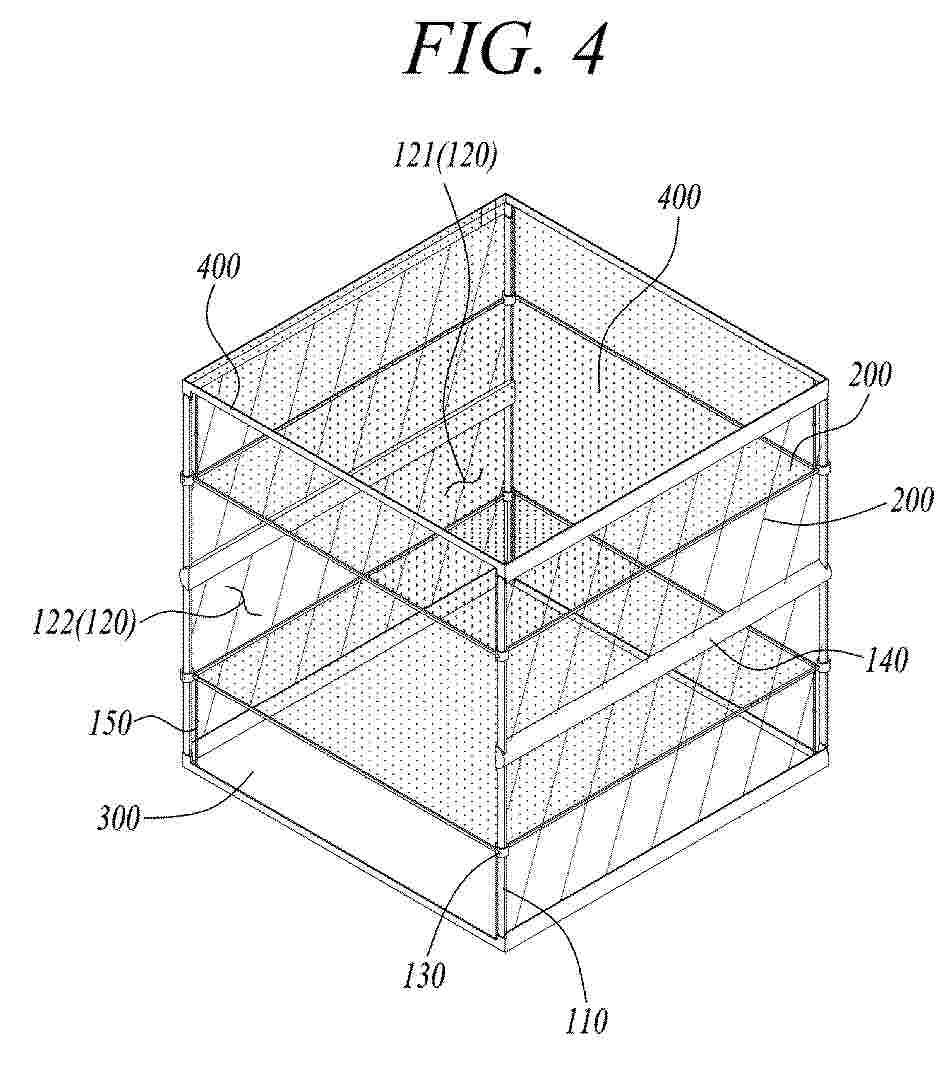
A three-dimensional foldable photovoltaic module is disclosed. The three-dimensional foldable photovoltaic module of the present disclosure can be installed at a desired location without a spatial restriction to generate energy using sunlight. Therefore, the present disclosure can enable efficient photovoltaic power generation without being limited by space.
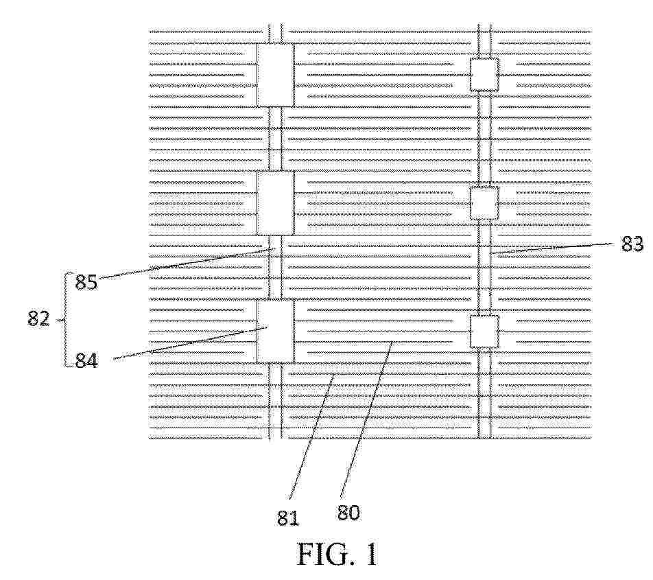
Resumen de: EP4730962A1
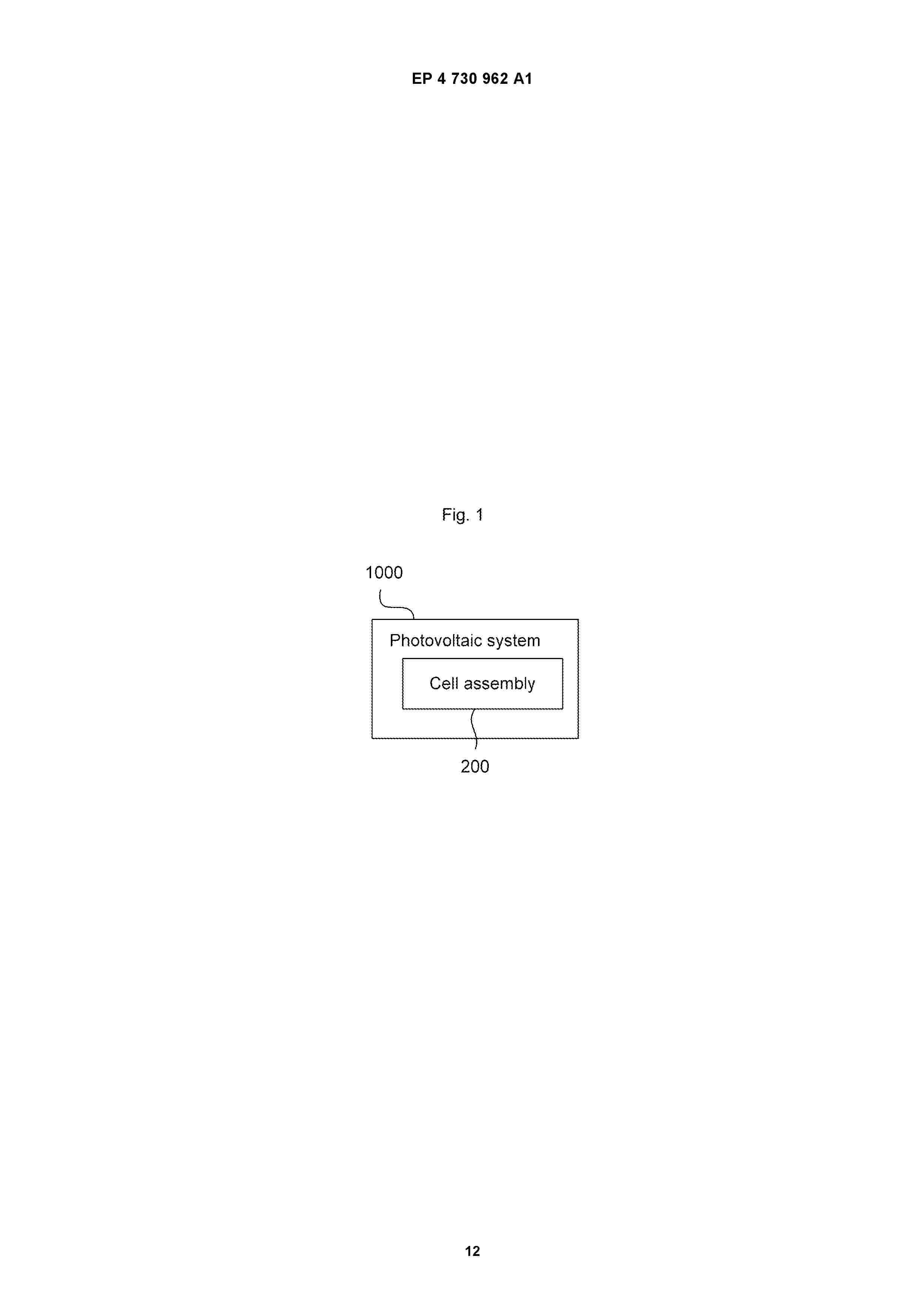
0001 The present disclosure is applicable to the technical field of solar cells, and provides a Topcon solar cell (100), a cell assembly (200), and a photovoltaic system (1000). A silicon substrate (10) of the Topcon solar cell (100) has a first surface (11) and a second surface (12) opposite to each other. A first tunneling oxide layer (20), a first polarity doped layer (30), and a first passivation layer (40) are sequentially stacked on the first surface (11), and a second polarity doped layer (50) and a second passivation layer (60) are sequentially stacked on the second surface 12. A first metal electrode (70) is arranged on the first passivation layer (40), and a second metal electrode (80) is arranged on the second passivation layer (60). In an extension direction of the first metal electrode (70), a plurality of first barrier isolation layers (90) arranged at intervals are located below the first metal electrode (70), and the first metal electrode (70) is made of a burn-through paste. At a position corresponding to the first barrier isolation layer (90), the first metal electrode (70) burns through the first passivation layer (40) to be in contact with the first barrier isolation layer (90), and between two adjacent first barrier isolation layers (90), the first metal electrode (70) burns through the first passivation layer (40) to be in contact with the first polarity doped layer (30), wherein the first barrier isolation layer (90) is obtained by partially removing
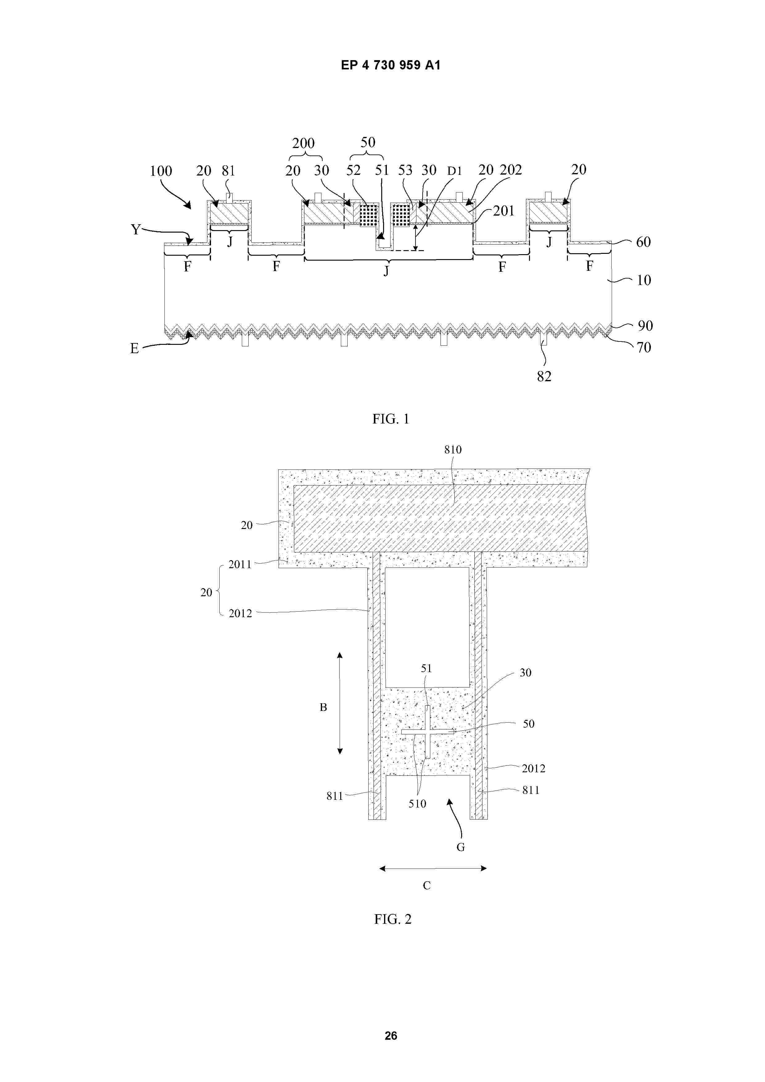
Resumen de: EP4730959A1
0001 The present disclosure relates to a solar cell, a preparation method thereof, and a photovoltaic module. The solar cell includes a substrate including a first surface, a passivating contact structure disposed on a part of the first surface, and a first electrode disposed on a side of the passivating contact structure away from the substrate and electrically connected to the passivating contact structure. A marking portion is disposed on a part of the passivating contact structure.
Resumen de: EP4730964A2
0001 The present application discloses a solar cell and a photovoltaic module, and belongs to the field of photovoltaic technologies. The solar cell includes a first pattern region, the first pattern region includes a plurality of first fingers extending along a first direction and arranged at intervals along a second direction, each of the first fingers includes a plurality of first connection segments disposed at intervals along the first direction and second connection segments connected between two adjacent first connection segments, and the second direction intersects with the first direction. A plurality of second connection segments are arranged at intervals along the second direction, and at least one of the first connection segments is disposed between two adjacent second connection segments. The first connection segments burn through the passivation layer and are electrically connected to the doped region, and the second connection segments do not burn through the passivation layer.
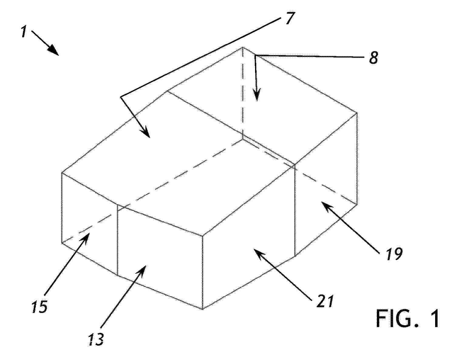
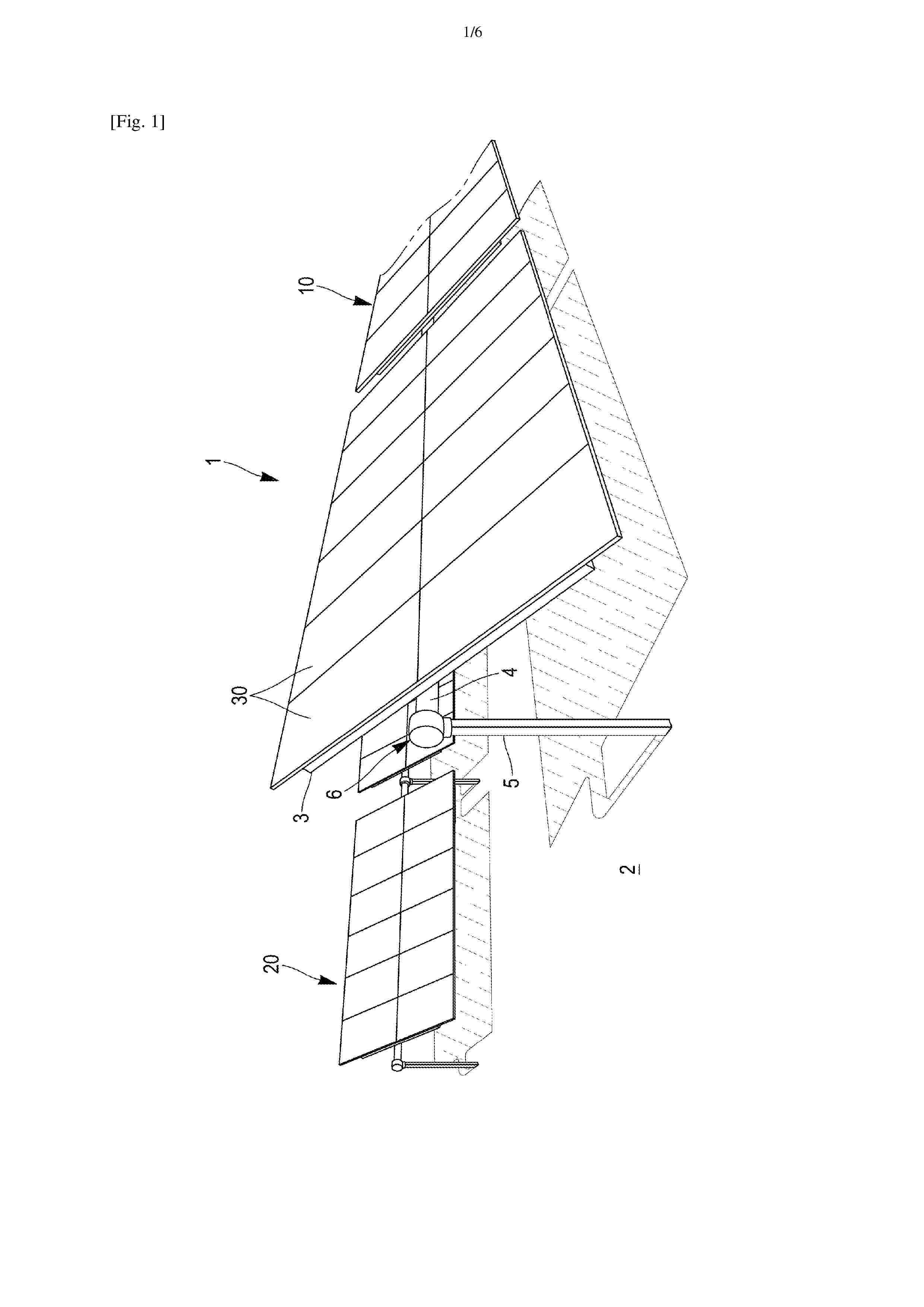
Resumen de: EP4730643A1
0001 Es wird ein Tragblock (1) einer Unterkonstruktion für ein Solarmodul (2), umfassend - eine erste im Wesentlichen ebene Aufstandsfläche (3) an einer Unterseite (4), - eine erste im Wesentlichen ebene Abstützfläche (7) und eine zweite im Wesentlichen ebene Abstützfläche (8) an einer Oberseite (9), wobei die zweite Abstützfläche (8) parallel zu der ersten Aufstandsfläche (3) ist, wobei die erste Abstützfläche (7) um einen ersten Winkel (α) gegenüber der ersten Aufstandsfläche (3) abgewinkelt ist, - eine zweite im Wesentlichen ebene Aufstandsfläche (10) an einer ersten Querseite (11) des Tragblocks (1), - eine dritte im Wesentlichen ebene Abstützfläche (13) an einer zweiten Querseite (14), wobei die dritte Abstützfläche (13) um einen zweiten Winkel (β) gegenüber der zweiten Aufstandsfläche (10) abgewinkelt ist, wobei der erste Winkel (α) im Wesentlichen gleich groß wie der zweite Winkel (β) ist, vorgeschlagen.
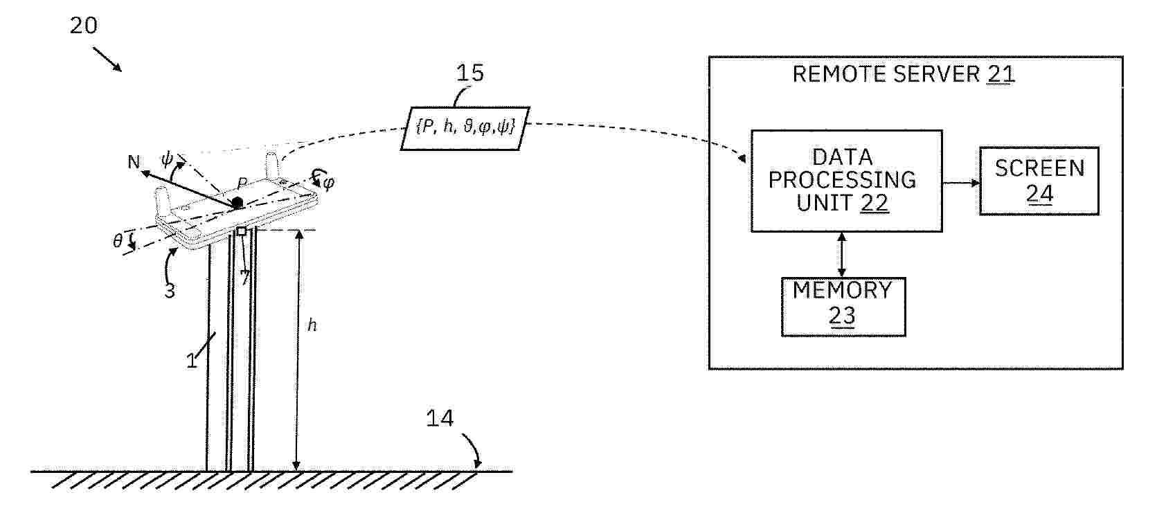
Resumen de: EP4730645A1
0001 Device and system for controlling pile driving in photovoltaic plants. The pile driving control device (3) comprises: a fastening system for to a pile (1) of a photovoltaic plant (2); a geolocation system (6) configured to measure the position (P) of the pile (1); a distance sensor (7) configured to measure the height (h) of the pile (1) relative to the ground (14); a tilt sensor (8) configured to measure the vertical inclination of the pile (1); an orientation measuring unit (9) configured to measure the orientation (Ψ) of the pile (1); a wireless communications module (10); a battery (11); and a control unit (12) configured for wireless reception and transmission of the measurements (15) from the sensors to a remote server (21). 0002 The pile driving control system (20) incorporates a remote server (21) that receives the measurements and verifies the proper installation of the piles (1).
Resumen de: EP4730960A1
0001 A photovoltaic cell string, a photovoltaic cell panel and a photovoltaic cell module, which are applied to the field of photovoltaic cell preparation. The cell string comprises: a plurality of cells, welding strips, which are arranged on first surfaces and second surfaces of the cells, and protective films, which are arranged on outer sides of the welding strips, wherein there is an overlapping region between adjacent cells among the plurality of cells; and the protective films located on preset cell surfaces of the adjacent cells extend to the overlapping region, such that by using the protective films, the stress generated between the cells and the welding strips in the overlapping region is reduced; the preset cell surfaces are the surfaces of the sides of the adjacent cells where the cells are stacked on each other; and the adjacent cells form an electrical connection by means of the welding strips located on the preset cell surfaces. In the present application, the protective films located on the preset surfaces of the cells in the adjacent cells extend to the overlapping region, such that the stress generated between the cells and the welding strip can be reduced.
Nº publicación: FR3167466A1 17/04/2026
Solicitante:
TSE [FR]
TSE
Resumen de: FR3167466A1
La présente invention concerne un procédé mis en œuvre par ordinateur permettant d’optimiser la conception d’une centrale photovoltaïque comprenant une structure positionnée sur un support, une pluralité d'unités de production d'électricité connectées à ladite structure, chacune des unités de production d'électricité étant conçue pour modifier leur orientation par rapport au soleil afin d'optimiser leur production d'électricité à tout moment, lesdites unités de production d'électricité étant connectées à des moyens de commande permettant de contrôler ladite orientation. Figure de l’abrégé : Figure 3
 BOPI
BOPI
 Sede Electrónica