Si deseas distinguir tus productos, servicios o ambos de los de otra empresa, es posible que necesites una marca o nombre comercial. Descubre qué son, en qué consiste su procedimiento de registro y qué implica.

Información sobre los plazos de presentación de solicitudes de transformación de marcas de la Unión Europea en marca nacional española. Más información


Si tienes un nuevo dispositivo, producto o procedimiento que resuelva un problema técnico o tenga una ventaja práctica, existen distintas formas de protegerlo en España y en otros países. Descubre cómo hacerlo.

¿Tu innovación reside en la estética, la ornamentación o la apariencia de tu producto? Protégela mediante un diseño industrial. Descubre qué derechos confiere el registro y cómo realizar la tramitación.

Las indicaciones geográficas protegen el nombre de un producto originario de una zona geográfica, a la cual le debe una determinada calidad, reputación u otra característica. Descubre qué son, en qué consiste su procedimiento de registro y qué beneficios conceden.

Las patentes publicadas en todo el mundo son una valiosa fuente de información científica, técnica y comercial.

Si eres emprendedor/a o una empresa y quieres potenciar y mejorar la rentabilidad de tu negocio protegiendo de forma adecuada los activos intangibles de tu organización, en este espacio encontrarás lo necesario.


 1450
resultados
1450
resultados
 Última actualización
08/05/2026 [07:34:00]
Última actualización
08/05/2026 [07:34:00]


 Resultados 25 a 50 de 1450

Resumen de: DE102025143796A1
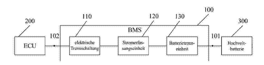
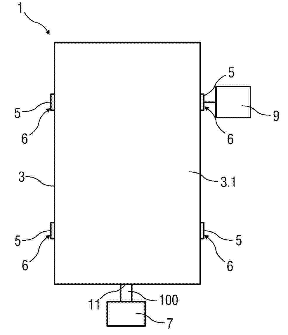
Die vorliegenden Offenbarung stellt ein Batteriemanagementsystem und ein Fahrzeug bereit, wobei das Batteriemanagementsystem (100) Folgendes umfasst: einen ersten Anschluss (101), der mit einer Hochvoltbatterie (300) verbunden ist; einen zweiten Anschluss (102), der mit einer elektronischen Steuereinheit (200) verbunden ist; eine elektrische Trennschaltung (110), die dazu konfiguriert ist, über den zweiten Anschluss (102) einen ersten Strom von der elektronischen Steuereinheit (200) zu empfangen; eine Stromerfassungseinheit (120), die dazu konfiguriert ist, einen von der elektrischen Trennschaltung (110) ausgegebenen zweiten Strom zu erfassen und als Reaktion darauf, dass der zweite Strom einen ersten Schwellenwert überschreitet, ein Trennsignal zu erzeugen; eine Batterietrenneinheit (130), die dazu konfiguriert ist, als Reaktion auf das Trennsignal die Hochvoltbatterie (300) von einer an diese Hochvoltbatterie (300) angeschlossenen Last zu trennen, wobei die elektrische Trennschaltung (110) eine Optokopplerschaltung umfasst.

Resumen de: DE102024131972A1
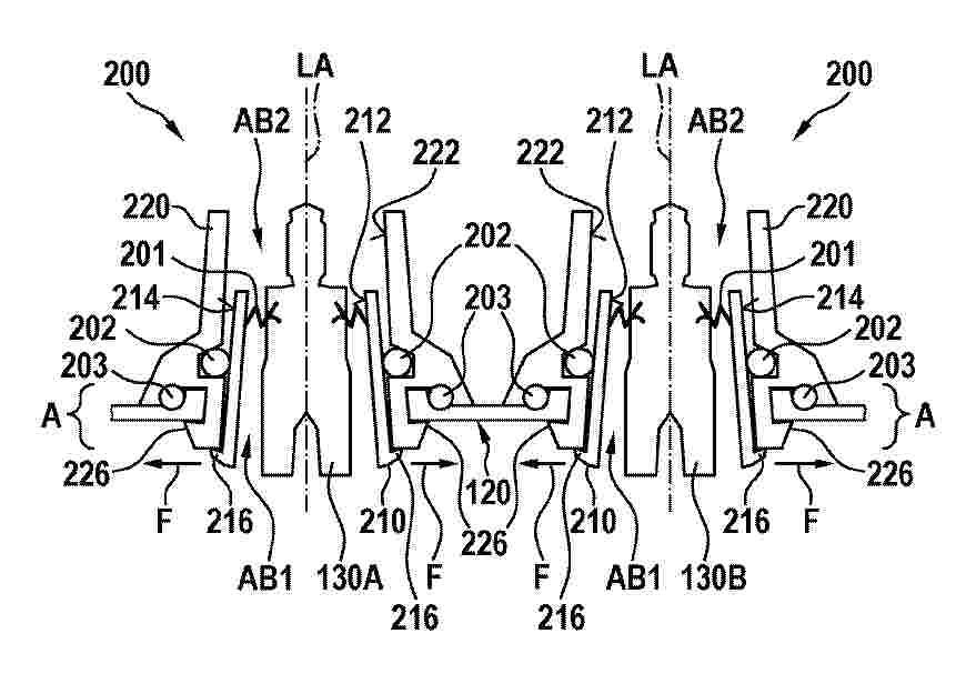
Die vorliegende Offenbarung betrifft eine Adapteranordnung (200) für elektrische Anschlüsse (130A, 130B) eines Antriebsenergiespeichers (100), umfassend:- eine erste Adaptereinheit (210), die einen ersten Aufnahmebereich (AB1) für einen elektrischen Anschluss (130A, 130B) aufweist, wobei an einer Innenwand (212) des ersten Aufnahmebereichs (AB1) wenigstens ein erstes Dichtelement (201) angeordnet ist, das eingerichtet ist, um einen Bereich zwischen der Innenwand (212) des ersten Aufnahmebereichs (AB1) und dem elektrischen Anschluss (130A, 130B) abzudichten; und- eine zweite Adaptereinheit (220), die einen zweiten Aufnahmebereich (AB2) für die erste Adaptereinheit (210) aufweist, wobei zwischen einer Innenwand (222) des zweiten Aufnahmebereichs (AB2) und der ersten Adaptereinheit (210) wenigstens ein zweites Dichtelement (202) anordenbar ist, um einen Bereich zwischen der Innenwand (222) des zweiten Aufnahmebereichs (AB2) und einer Außenwand (214) der ersten Adaptereinheit (210) abzudichten,- wobei die Adapteranordnung (200) in eine Gehäuseöffnung eines Gehäuses (120) einsetzbar ist, und wobei ein Außenabschnitt der ersten Adaptereinheit (210) eingerichtet ist, um eine Kraft (F) auf die Innenwand (222) des zweiten Aufnahmebereichs (AB2) auszuüben, um die zweite Adaptereinheit (220) in der Gehäuseöffnung zu fixieren.
Resumen de: DE102024132436A1
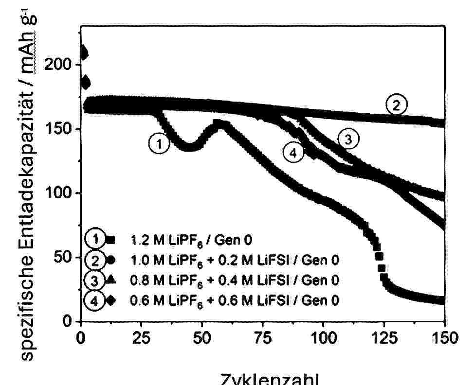
Die vorliegende Erfindung betrifft eine Lithiumsekundärbatterie, umfassend eine Anode, eine Kathode und einen nichtwässrigen Elektrolyten; wobei der nichtwässrige Elektrolyt ein nichtwässriges Lösungsmittel und ein Lithiummischsalz umfasst; das Lithiummischsalz ein Fluorsulfonylimid-basiertes Lithiumsalz und LiPF6umfasst; die Kathode einen Kathodenstromabnehmer umfasst; der Kathodenstromabnehmer Aluminium umfasst; die Kathode ferner ein Kathodenaktivmaterial umfasst; und das Kathodenaktivmaterial lithiummanganreiches Oxid umfasst.
Resumen de: DE102024210634A1
Die Erfindung betrifft ein Verfahren zur Herstellung einer Traktionsbatterie, welche ein Batteriegehäuse, mehrere im Batteriegehäuse angeordnete Batteriezellen (110) und eine Kühleinrichtung (300) für die Batteriezellen (110) aufweist, mit den Schritten:- Bereitstellen eines Batteriegehäuseunterteils (200) und wenigstens eines Batteriemoduls (100), das mehrere zu einem Zellstapel angeordnete prismatische Batteriezellen (110) aufweist;- Anordnen des Batteriemoduls (100) im Batteriegehäuseunterteil (200);- Auftragen eines flüssigen oder pastösen Wärmeleitmediums auf die Batteriezellen (110) des im Batteriegehäuseunterteils (200) angeordneten Batteriemoduls (100), wobei das Auftragen des Wärmeleitmediums mithilfe einer Flachdüse erfolgt;- Aufsetzen wenigstens einer die Batteriezellen (110) abdeckenden Kühleinrichtung (300).Die Erfindung betrifft ferner verschiedene Ausführungsmöglichkeiten einer Flachdüse zum Auftragen des Wärmeleitmediums.
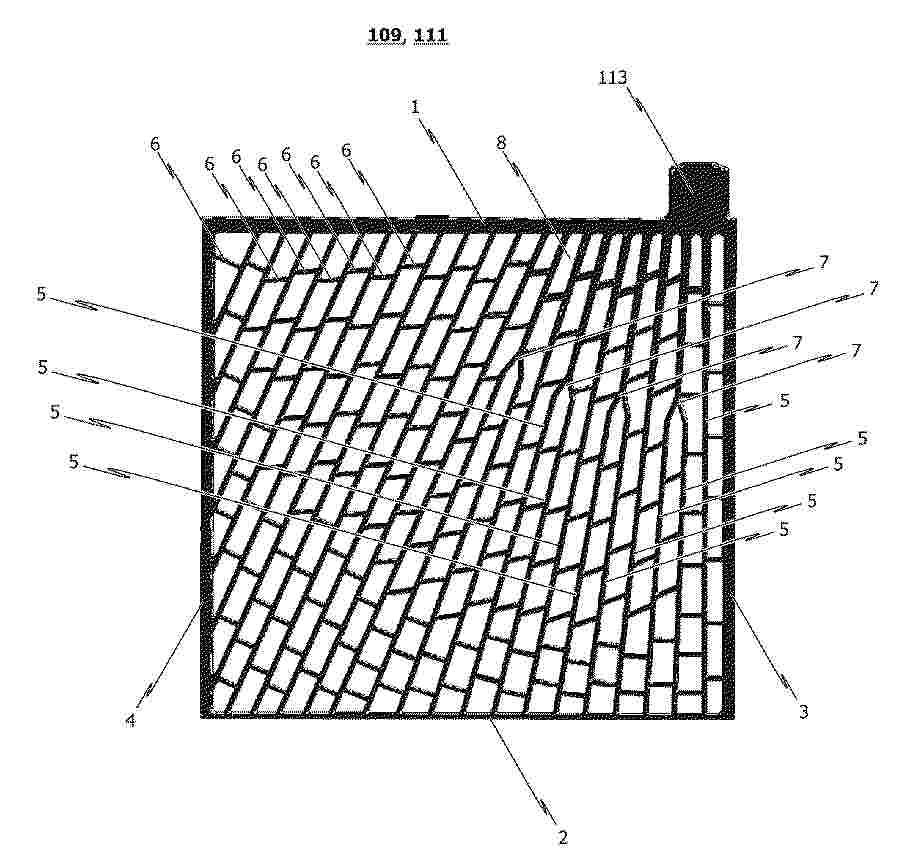
Resumen de: DE102024132537A1
Die Erfindung betrifft eine Gitteranordnung (109, 111) für eine plattenförmige Batterieelektrode eines elektrochemischen Akkumulators (100), wobei die Gitteranordnung (109, 111) einen Rahmen und ein im Inneren des Rahmens an dem Rahmen angeordnetes Gitter aufweist, wobei der Rahmen ein oberes Rahmenelement (1), an dessen dem Gitter abgewandter Seite eine Anschlussfahne (113) der Batterieelektrode angeordnet ist, ein dem oberen Rahmenelement (1) gegenüberliegendes unteres Rahmenelement (2) und zwei einander gegenüberliegende und jeweils das obere und untere Rahmenelement (1, 2) verbindende seitliche Rahmenelemente (3, 4) aufweist, wobei die Anschlussfahne (113) an oder in einem ersten Endbereich des oberen Rahmenelements (1) mit dem oberen Rahmenelement (1) verbunden ist, und wobei ein erstes seitliches Rahmenelement (3) der beiden seitlichen Rahmenelemente (3, 4) den ersten Endbereich des oberen Rahmenelements (1) mit dem unteren Rahmenelement (2) verbindet und das zweite seitliche Rahmenelement (4) einen dem ersten Endbereich des oberen Rahmenelements (1) gegenüberliegenden zweiten Endbereich des oberen Rahmenelements (1) mit dem unteren Rahmenelement (2) verbindet. Erfindungsgemäß ist insbesondere vorgesehen, dass das Gitter eine Vielzahl von vertikalen Gitterstreben (5) aufweist, wobei jede vertikale Gitterstrebe (5) einen ersten Endbereich aufweist, der mit dem oberen Rahmenelement (1) verbunden ist, und mindestens einen dem ersten Endbereich zumindest teil- oder b
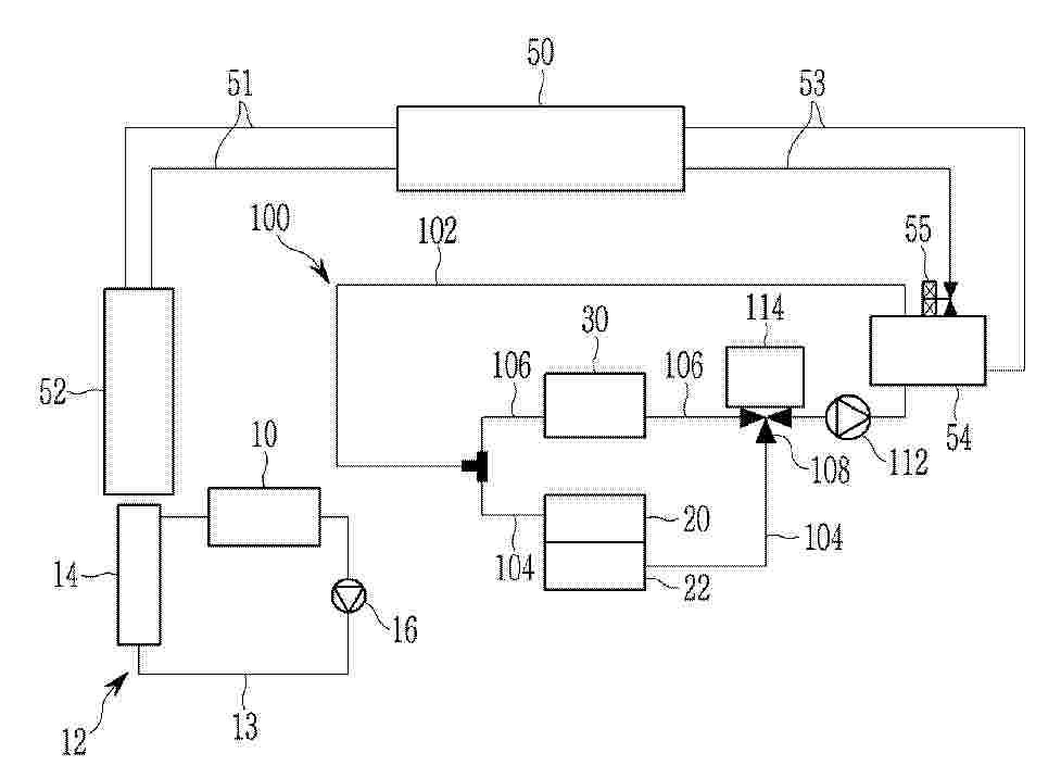
Resumen de: DE102025124063A1
Wärmemanagementsystem für ein Fahrzeug, aufweisend einen Elektromotor (10), ein Batteriemodul (20), eine Klimaanlage (50), die einen Kondensator (52) und einen Chiller (54) aufweist und ein Kältemittel zirkuliert, und eine Kühlvorrichtung (100), die eine Kühlmittelleitung (102) aufweist, die mit dem Chiller (54) verbunden ist, um das Batteriemodul (20) und ein elektrisches Bauteil (30) durch ein mit dem Kältemittel in dem Chiller (54) wärmegetauschtes Kühlmittel zu kühlen, wobei die Kühlmittelleitung (102) eine erste Verbindungsleitung (104), in welcher das Batteriemodul (20) vorgesehen ist, und eine zweite Verbindungsleitung (106) aufweist, in welcher das elektrische Bauteil (30) mit Ausnahme des Elektromotors (10) vorgesehen ist, und wobei die erste Verbindungsleitung (104) und die zweite Verbindungsleitung (106) parallel zueinander konfiguriert sind.
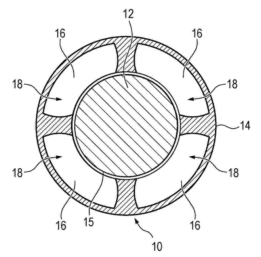
Resumen de: DE102024132428A1
Die Erfindung betrifft eine einfach und kostengünstig herstellbare Stromleitung (10, 11) für ein Elektrofahrzeug, umfassend einen Leiter (12) und eine den Leiter (12) umschließende Isolationsstruktur (14), wobei in der Isolationsstruktur (14) wenigstens ein entlang einer Längsrichtung der Isolationsstruktur (14) verlaufender Zwischenraum (16) ausgebildet ist. Durch den Zwischenraum (16) kann ein Kühlmedium (18) fließen und dadurch Brandrisiken und dergleichen senken. In den Rahmen der Erfindung fällt des Weiteren eine Batterie (112).
Resumen de: DE102025144929A1
Eine Batteriepackbaugruppe beinhaltet eine Einkapselungsbaugruppe, die einen Innenbereich bereitstellt. Batteriezellen sind entlang einer Arrayachse angeordnet und sind innerhalb des Innenbereichs positioniert. Jede der Batteriezellen beinhaltet mindestens einen Flachsteckeranschluss, der von der Arrayachse nach außen vorsteht. Eine Abschirmbaugruppe beinhaltet einen Schaumstoff, der an einem Stützstab gesichert ist. Die Abschirmbaugruppe befindet sich neben den Batteriezellen innerhalb des Innenbereichs.
Resumen de: DE102024132176A1
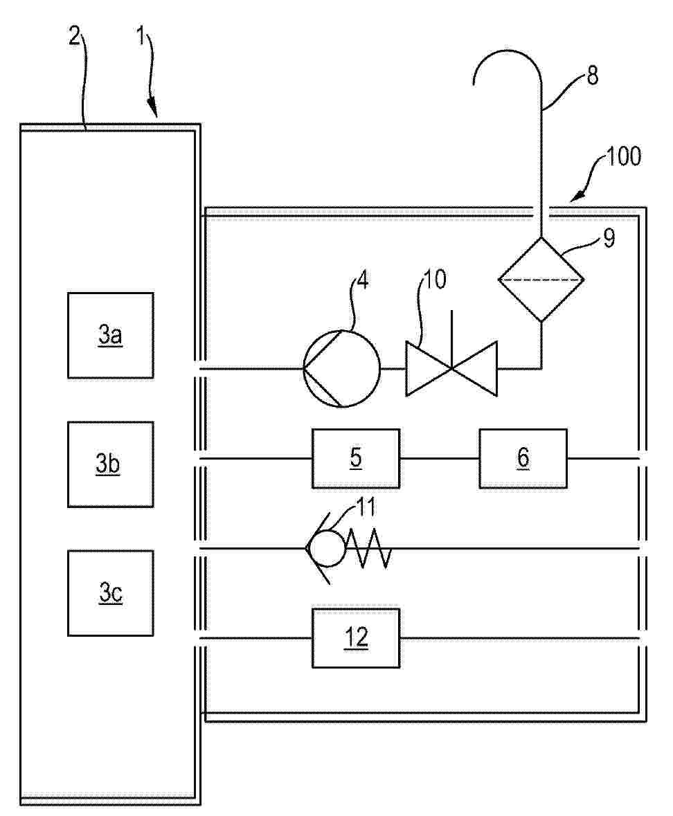
Die Erfindung betrifft ein Verfahren zur Überprüfung der Dichtigkeit einer Hochvoltbatterie (1) eines Kraftfahrzeugs, die ein Batteriegehäuse (2) und eine Mehrzahl von Batteriezellen (3a-3c) aufweist, die innerhalb des Batteriegehäuses (2) untergebracht sind, umfassend die Schritte:- Erzeugen eines definierten Überdrucks innerhalb des Batteriegehäuses (2) der Hochvoltbatterie (1) gegenüber der Umgebung mittels einer Pumpvorrichtung (4),- Messen des Drucks innerhalb des Batteriegehäuses (2) mittels eines Drucksensors (5),- Auswerten eines zeitlichen Verlaufs des gemessenen Drucks mittels einer Druckauswerteeinrichtung (6), dadurch gekennzeichnet, dass der Überdruck innerhalb des Batteriegehäuses (2) gegenüber der Umgebung dauerhaft aufrechterhalten wird.
Resumen de: DE102024132003A1
Verfahren zum Betrieb eines Flurförderzeugs mit• mindestens einem elektrischen Energiespeicher,• mindestens einem elektrischen Verbraucher und• einem Energiespeicherfahrzeuginterface, das eine Energiespeicherklemme, eine erste Verbraucherklemme und einen vorzugsweise wiederbeschreibbaren Datenspeicher aufweist, auf dem Energiespeicherinformationen über den Energiespeicher gespeichert sind,• wobei der Energiespeicher an die Energiespeicherklemme angeschlossen ist, der mindestens eine Verbraucher an die erste Verbraucherklemme angeschlossen ist, die erste Verbraucherklemme geöffnet oder geschlossen sein kann und die Energiespeicherklemme mit der ersten Verbraucherklemme elektrisch verbunden ist, wenn die erste Verbraucherklemme geschlossen ist,umfassend die Schritte:• Messen einer an der Energiespeicherklemme anliegenden Energiespeicherspannung und vorzugsweise eines über die Energiespeicherklemme fließenden Energiespeicherstroms,• Ermitteln eines Energiespeicherzustandskennwertes unter Verwendung der Energiespeicherinformationen und der Energiespeicherspannung sowie vorzugsweise des Energiespeicherstroms,• Öffnen der ersten Verbraucherklemme in Abhängigkeit des Energiespeicherzustandskennwertes,• vorzugsweise Laden des Energiespeichers und• erneutes Schließen der ersten Verbraucherklemme in Abhängigkeit des Energiespeicherzustandskennwertes.
Resumen de: DE102025131948A1
Eine Energiespeichervorrichtung umfasst mindestens eine Energiespeicherzelle, eine Bodenwand, ein Paneelelement, das unter der Bodenwand vorgesehen ist, und ein Schutzelement, das an der Bodenwand vorgesehen ist. Ein Sicherheitsventil ist in einer unteren Fläche der Energiespeicherzelle vorgesehen. Die Bodenwand weist ein Durchgangsloch auf, das an einer Position vorgesehen ist, die dem Sicherheitsventil zugewandt ist. Das Schutzelement umfasst ein Thermalisolierungselement, das sich in dem Durchgangsloch befindet. Das Thermalisolierungselement umfasst eine Empfangsfläche, die unter einer oberen Fläche der Bodenwand liegt.
Resumen de: DE102025145168A1
Eine Batterie beinhaltet in einem Beispiel eine positive Elektrode und eine negative Elektrode, wobei die negative Elektrode Aktivmaterialflocken mit nichthydroxylierte Ebenen umgebenden hydroxylierten Kanten beinhaltet. Hydroxylierte Metalloxidnanopartikel werden an die hydroxylierten Kanten chemisorbiert, wodurch diese Bereiche selektiv beschichtet werden. Die Metalloxidnanopartikel können Wolfram, Niob oder Aluminium sein.
Resumen de: DE102026111156A1
Die Erfindung betrifft ein Verfahren und eine Vorrichtung (1) zur Überprüfung einer Dichtheit eines elektrischen Energiespeichers (3) mit mindestens einer Berstscheibe (5), und umfasst folgende Verfahrensschritte: 1.) Beaufschlagen des elektrischen Energiespeichers (3) mit einem Überdruck durch Befüllen des elektrischen Energiespeichers (3) mit einem Gas (100) durch eine Befülleinheit (7), 2.a) Ermitteln eines physikalischen Wertes an genau einer Berstscheibe (5) durch eine Messeinheit (9), wobei zusätzliche Berstscheiben (5) des elektrischen Energiespeichers (3) abgedeckt werden, und/oder 2.b) Ermitteln eines gleichen physikalischen Wertes an allen Berstscheiben (5) des elektrischen Energiespeichers (3) durch die Messeinheit (9) und/oder Bilden eines Summenwertes aller ermittelten gleichen physikalischen Werte, 3.) Abgleichen des ermittelten physikalischen Wertes und/oder des Summenwertes mit einem hinterlegten Vergleichswert für den physikalischen Wert und/oder den Summenwert, und 4.) Speichern des ermittelten physikalischen Wertes und/oder des Summenwertes des elektrischen Energiespeichers (3).
Resumen de: DE102025145117A1
Die vorliegende Offenbarung betrifft eine Vorrichtung und ein Verfahren zum Detektieren einer Batterieanomalie unter Verwendung einer Spannungsabweichungsvariation. Gemäß einer Ausführungsform der vorliegenden Offenbarung beinhaltet die Vorrichtung: einen Speicher, der dazu angepasst ist, mindestens eine Anweisung zum Detektieren einer Batterieanomalie unter Verwendung einer Spannungsabweichungsvariation zu speichern; und einen Prozessor, der dazu angepasst ist, einen Betrieb gemäß der Anweisung durchzuführen, wobei der Prozessor zu Folgendem angepasst ist: Berechnen einer Spannungsänderung der Batterie und Speichern der berechneten Spannungsänderung als eine Variable; und Berechnen einer Differenzabweichungsspannungsdetektion (DDVD), die eine Änderung der Spannungsdifferenz zwischen jeweiligen Zellen innerhalb eines Batteriemoduls ist, und Detektieren einer Batterieanomalie unter Verwendung der Spannungsabweichungsvariation (DDVD) und der gespeicherten Variablen.
Resumen de: DE102025120217A1
Batterie mit einem Batterieunterbringungsabschnitt (100), der einen Elektrodenstapel (1) mit einer Elektrode und einem Separator beherbergt, und einem Kühlabschnitt (200) mit ausgesparten Nuten (210), welche in einer Plattenfläche des Kühlabschnitts (200) ausgebildet sind, wobei der Kühlabschnitt (200) so angeordnet ist, dass er fest an einer Außenfläche des Batterieunterbringungsabschnitts (100) angebracht ist und Strömungswege (220) in einem Raum zwischen den ausgesparten Nuten (210) und der Außenfläche des Batterieunterbringungsabschnitts (100) definiert, so dass ein Kältemittel entlang der Strömungswege (220) strömt, so dass die Leistungsfähigkeit bei der Abfuhr von Wärme von einer Batteriezelle verbessert werden kann, eine Schnellladezeit verkürzt wird, eine hohe Leistungsausgabe der Batteriezelle sichergestellt wird und Kosten und Gewicht reduziert werden.
Resumen de: DE102025143843A1
Ein Tauchwärmeregulierungssystem für einen Traktionsbatteriepack beinhaltet ein Kühlmittelabgabesystem, das ein Kühlmittel aus einer Kühlmittelzufuhr zu einer Umhüllungsbaugruppe leitet, die eine Vielzahl von Batteriezellen unterbringt. Das Kühlmittelabgabesystem beinhaltet eine Vielzahl von Einlassdurchbrüchen zu der Umhüllungsbaugruppe. Ein Kühlmittelrückführsystem leitet das Kühlmittel aus der Umhüllungsbaugruppe zurück zu der Kühlmittelzufuhr. Das Kühlmittelrückführsystem beinhaltet mindestens einen Auslassdurchbruch von der Umhüllungsbaugruppe.
Resumen de: DE102025145165A1
Es werden Systeme und Verfahren zum Kühlen von Batteriezellen einer Batterie beschrieben. Das System kann eine Vielzahl von Schieberventilen beinhalten, um eine Vielzahl von Kühlmittelströmungswegen durch einen Batteriepack zu erzeugen, sodass eine Temperaturdifferenz zwischen Batteriezellen verringert werden kann. Eine Steuerung stellt Positionen der Schieberventile gemäß der Batteriezellentemperatur ein.
Resumen de: DE102025132020A1
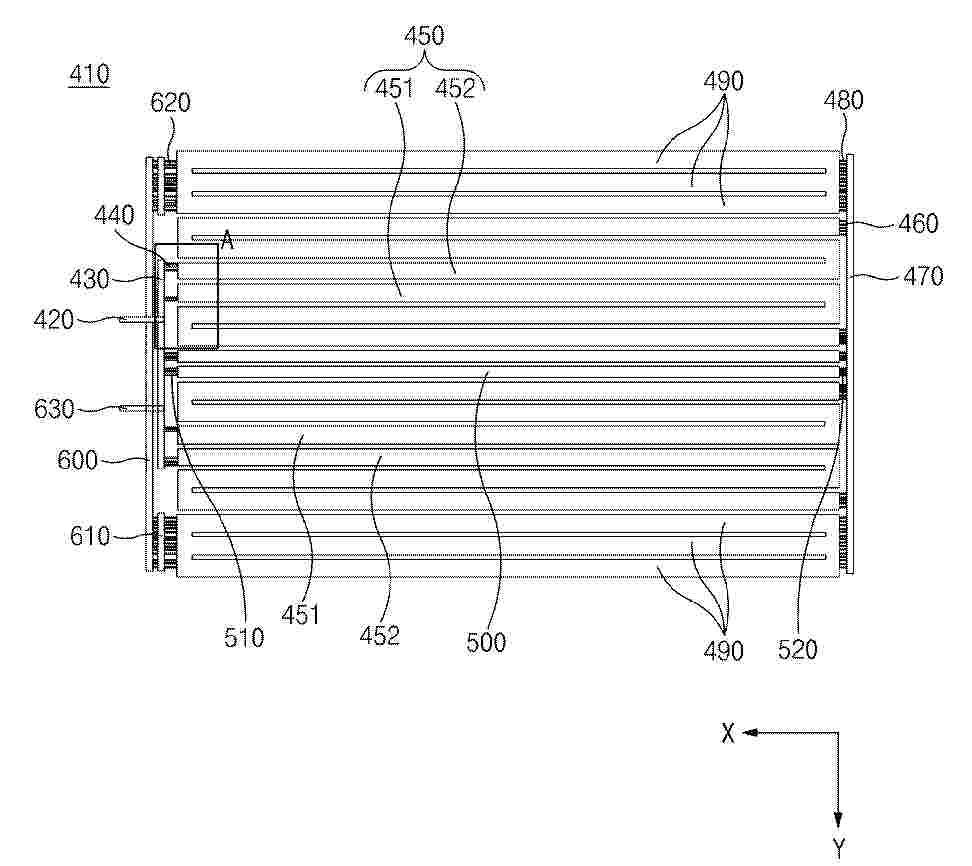
Ein Kühlmodul, das aufweist: einen Zulaufverteilerblock (430), der mit einer Einlassleitung (420) verbunden ist, in das Kühlwasser eingeleitet wird, und der das Kühlwasser verteilt, einen Sammelverteilerblock (600), der mit einer Auslassleitung (630) verbunden ist, aus dem das Kühlwasser ausgegeben wird, und der das Kühlwasser sammelt und an die Auslassleitung (630) zuführt, eine Mehrzahl von ersten Kanälen (450), die einen Abschnitt aufweisen, der mit dem Zulaufverteilerblock (430) verbunden ist, einen Rücklaufverteilerblock (470), der mit der Mehrzahl von ersten Kanälen (450) verbunden ist und eine Strömungsrichtung des von der Mehrzahl von ersten Kanälen (450) zugeführten Kühlwassers ändert, eine Mehrzahl von zweiten Kanälen (490), die den Rücklaufverteilerblock (470) und den Sammelverteilerblock (600) verbinden, und einen Bypasskanal (500), der die ersten Kanäle umgeht, das Kühlwasser vom Zulaufverteilerblock aufnimmt und das Kühlwasser durch eine Passage, die kürzer ist als die ersten Kanäle, zum Rücklaufverteilerblock (470) zuführt.
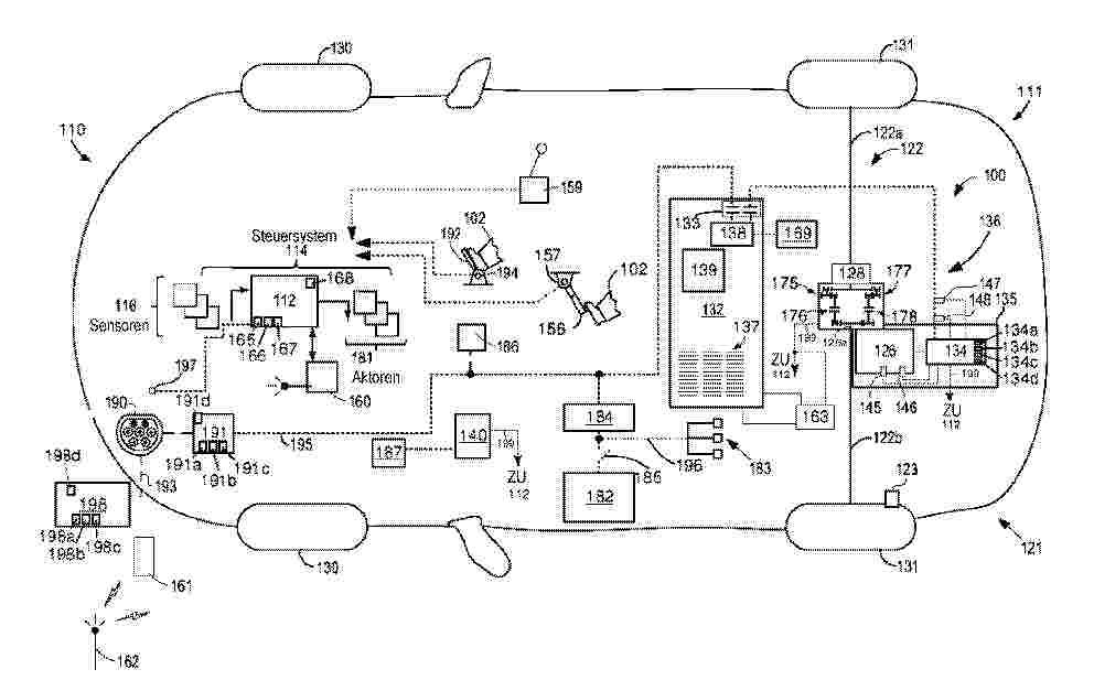
Resumen de: DE102025131946A1
Fahrzeug, das durch Verbinden mit einer externen Ladevorrichtung geladen werden kann, umfasst ein Navigationssystem, in dem ein Ziel des Fahrzeugs eingestellt wird, eine Batterie, die elektrische Energie speichert, die von der externen Ladevorrichtung geliefert wird, eine Kühlvorrichtung, die die Batterie kühlt, und eine elektronische Steuereinheit (ECU), die die Kühlvorrichtung steuert. Wenn die externe Ladevorrichtung als Ziel in dem Navigationssystem eingestellt wird, bezieht die ECU einen Maximalstrom der externen Ladevorrichtung von dem Navigationssystem, berechnet einen Vorhersagewert hinsichtlich dessen, wie der SOC der Batterie sein wird, wenn das Fahrzeug das Ziel erreicht, basierend auf Navigationsinformationen von dem Navigationssystem, und wenn der Maximalstrom einen Stromschwellenwert überschreitet und auch der vorhergesagte Wert gleich oder kleiner als ein erster SOC-Schwellenwert ist, betätigt die ECU die Kühlvorrichtung, bevor das Fahrzeug das Ziel erreicht.
Resumen de: DE102025120306A1
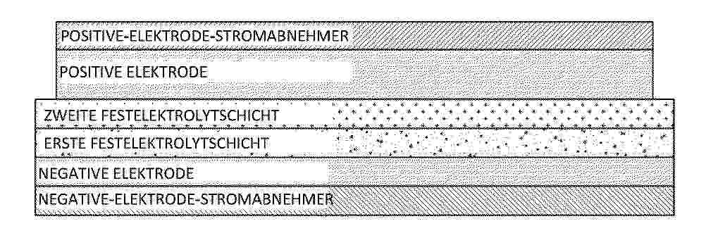
Festkörperbatterie, die einen Doppelschicht-Festelektrolyten aufweist, und Verfahren zum Herstellen dergleichen, wobei die Festkörperbatterie, die einen Doppelschicht-Festelektrolyten aufweist, die Robustheit verbessert und zugleich ein thermisches-Durchgehen-Phänomen unterdrückt und eine ausgezeichnete elektrochemische Charakteristik aufweist, sowie ein Verfahren zum Herstellen dergleichen. Die Festkörperbatterie weist eine negative Elektrode, eine erste Festelektrolytschicht, die auf der negativen Elektrode angeordnet ist, eine zweite Festelektrolytschicht, die auf der ersten Festelektrolytschicht angeordnet ist, und eine positive Elektrode, die auf der zweiten Festelektrolytschicht angeordnet ist, auf. Die erste Festelektrolytschicht weist ein anorganisches Flammschutzmittel auf, und die zweite Festelektrolytschicht weist ein endothermes Flammschutzmittel auf.
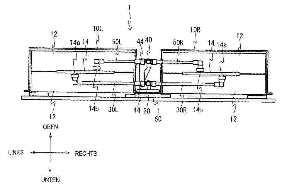
Resumen de: DE102025142499A1
Ein Batteriepack 1 umfasst: zwei Batteriemodule 10, die jeweils ein Kühlelement 14 zum Kühlen einer Batteriezelle 12 aufweisen und in der Links-Rechts-Richtung voneinander beabstandet sind; eine Zulaufleitung 20, die zwischen den zwei Batteriemodulen 10 in der Vorn-Hinten-Richtung angeordnet ist; zwei erste Zweigleitungen 30L und 30R, die von der Zulaufleitung 20 in der Links-Rechts-Richtung abzweigen und jeweils das Kältemittel in die Kühlelemente 14 der zwei Batteriemodule 10 leiten; eine Ablaufleitung 40, die zwischen den zwei Batteriemodulen 10 in der Vorn-Hinten-Richtung angeordnet ist; und zwei zweite Zweigleitungen 50L und 50R, die von der Ablaufleitung 40 entlang der Links-Rechts-Richtung abzweigen und in die das Kältemittel von dem Kühlelement 14 jedes der zwei Batteriemodule 10 abgegeben wird. Die Zulaufleitung 20 und die Ablaufleitung 40 sind in der vertikalen Richtung angeordnet.
Resumen de: DE102024132244A1
Vorgeschlagen ist Batteriemodul (1), aufweisend ein Gehäuse (2) und darin aufgenommene oder aufnehmbare Batteriezellen (3), wobei das Gehäuse einen Zulauf (4) und einen Ablauf (5) für Kühl- oder Kältemittel zur Temperierung der Batteriezellen hat. Das Gehäuse soll in Stapelbauweise aus Platinen (6) gebildet sein, die jeweils senkrecht zu deren Haupterstreckungsebene von Aufnahmeöffnungen (7) für die Batteriezellen und den Zu- und Ablauf bildenden Aussparungen (8, 9) durchsetzt sind und die jeweils parallel zu deren Haupterstreckungsebene verlaufende Durchlaufkanäle (10) für das Kühl- oder Kältemittel begrenzen.
Resumen de: DE102025144927A1
Ein Traktionsbatteriepackentlüftungssystem beinhaltet eine oder mehrere Batteriezellen und eine Entlüftungskammer benachbart zu der einen oder den mehreren Batteriezellen. Die eine oder mehreren Batteriezellen sind dazu konfiguriert, in die Entlüftungskammer entlüftet zu werden. Die Entlüftungskammer weist eine Innenwand und eine Außenwand auf. Die Außenwand kann Außenwandentlüftungsöffnungen beinhalten. Jede der Außenwandentlüftungsöffnungen ist dazu konfiguriert, Entlüftungsnebenprodukte aufzunehmen, die von einer der einen oder mehreren Batteriezellen abgegeben werden. Die Innenwand kann Innenwandeinlässe beinhalten, die jeweils dazu konfiguriert sind, Entlüftungsnebenprodukte aufzunehmen, die von einer der einen oder mehreren Batteriezellen abgegeben werden.
Resumen de: EP4738459A1
A lithium secondary battery and an electric device. The lithium secondary battery comprises a positive electrode sheet, the positive electrode sheet comprises a first active layer coated on at least one side of a positive electrode current collector and containing a positive electrode active material and a polycrystalline lithium supplementing agent and a second active layer coated on the side of the first active layer away from the current collector and containing a positive electrode active material, and the lithium supplementing agent comprises at least one of LixNi1-yMyO2, LixRO2, and LiNi α Co β Mn γ O2, wherein M comprises one or more of Cu, Al, and Mn; R comprises one of Ni and Mn; 1 < x < 2, 0 < y ≤ 0.01, α + β + γ =1 and α ≥ 0.5. The lithium supplementing agent rapidly releases sufficient active lithium during initial charge, thereby improving the energy density of a secondary battery, and persistently releases active lithium during a cycle, thereby slowing down the attenuation of a battery cell.
Nº publicación: EP4738501A1 06/05/2026
Solicitante:
LG ENERGY SOLUTION LTD [KR]
LG Energy Solution, Ltd.
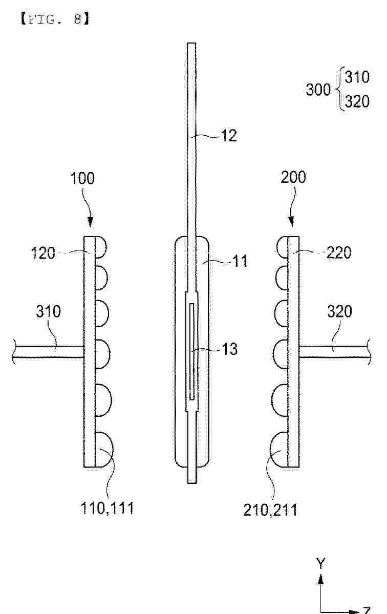
Resumen de: EP4738501A1
0001 Disclosed are a pouch-shaped secondary battery pressing apparatus for pressing a pouch-shaped secondary battery including a first pocket portion configured to receive an electrode assembly having a pair of electrode leads opposite to each other and a first sealed portion at an edge of the first pocket portion, the pouch-shaped secondary battery pressing apparatus including a first pressing unit configured to press one surface of the first pocket portion and a second pressing unit configured to press an other surface of the first pocket portion, wherein the first pressing unit has a first pressing pad with a plurality of first embossments facing the one surface of the first pocket portion, and the second pressing unit has a second pressing pad with a plurality of second embossments facing the other surface of the first pocket portion, and a pressing method using the same.
 BOPI
BOPI
 Sede Electrónica