Si deseas distinguir tus productos, servicios o ambos de los de otra empresa, es posible que necesites una marca o nombre comercial. Descubre qué son, en qué consiste su procedimiento de registro y qué implica.

Información sobre los plazos de presentación de solicitudes de transformación de marcas de la Unión Europea en marca nacional española. Más información


Si tienes un nuevo dispositivo, producto o procedimiento que resuelva un problema técnico o tenga una ventaja práctica, existen distintas formas de protegerlo en España y en otros países. Descubre cómo hacerlo.

¿Tu innovación reside en la estética, la ornamentación o la apariencia de tu producto? Protégela mediante un diseño industrial. Descubre qué derechos confiere el registro y cómo realizar la tramitación.

Las indicaciones geográficas protegen el nombre de un producto originario de una zona geográfica, a la cual le debe una determinada calidad, reputación u otra característica. Descubre qué son, en qué consiste su procedimiento de registro y qué beneficios conceden.

Las patentes publicadas en todo el mundo son una valiosa fuente de información científica, técnica y comercial.

Si eres emprendedor/a o una empresa y quieres potenciar y mejorar la rentabilidad de tu negocio protegiendo de forma adecuada los activos intangibles de tu organización, en este espacio encontrarás lo necesario.


 463
resultados
463
resultados
 Última actualización
25/04/2026 [07:54:00]
Última actualización
25/04/2026 [07:54:00]


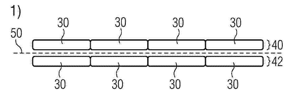
Resumen de: EP4530049A1
A method of producing a spar cap or a part thereof comprises providing a plurality of structural elements (30) each comprising fibres and a weldable resin; arranging at least two of the structural elements (30) side by side, thereby forming a first layer (40); arranging at least two further structural elements (30) side by side, thereby forming a second layer (42); placing a resistive element (50) between the first and second layers (40, 42); and while pressing the first and second layers (40, 42) together, energising the resistive element (50) such that the weldable resin softens or melts, thereby joining the first and second layers (40, 42) of structural elements (30). The structural elements (30) may be pultrusion planks.Also disclosed is a spar cap obtainable by this method as well as a wind turbine blade comprising such spar cap.

Resumen de: DE102025105470A1
Die vorliegende Erfindung betrifft einen Windkraftanlagen-Rotor (100), umfassend eine Welle (200), auf der Welle (200) montierte Rotorträger (300), eine Vielzahl von auf den Rotorträgern (300) montierten Blechpaketen (400), wobei zwischen den Blechpaketen (400) eine Vielzahl von Abstandshalterprofilen (500, 1500, 2500) angeordnet ist, die eine Vielzahl von Radialkanälen (600) zwischen axial benachbarten Blechpaketen (400) bildet. Die vorliegende Erfindung betrifft weiterhin eine Windkraftanlage, die mindestens einen erfindungsgemäßen Rotor (100) umfasst.
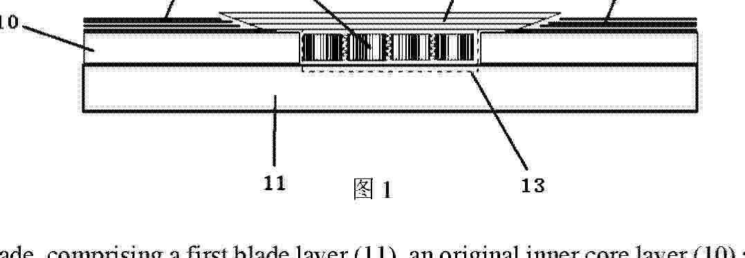
Resumen de: AU2023472641A1
A wind turbine blade, comprising a first blade layer (11), an original inner core layer (10) and a second blade layer (12) which are stacked, a repair through hole (16) being formed in the second blade layer, a damage removal hole (15) being formed in the original inner core layer, and the damage removal hole being communicated with the repair through hole and extending to the inner surface of the first blade layer. A recovery structure layer (17) connected to the second blade layer is provided at the repair through hole. One or more repair core members (14) are provided in the damage removal hole. By means of continuous filling and curing of adhesives, the one or more repair core members are connected to each other, and the repair core members are connected to the first blade layer, so as to form a repaired inner core layer. During maintenance of the power wind turbine blade in a wind farm, the device can achieve short maintenance time, simple operation, stable maintenance quality, excellent structural performance after maintenance, and lower maintenance cost. Also disclosed is a rapid maintenance method for a wind turbine blade.
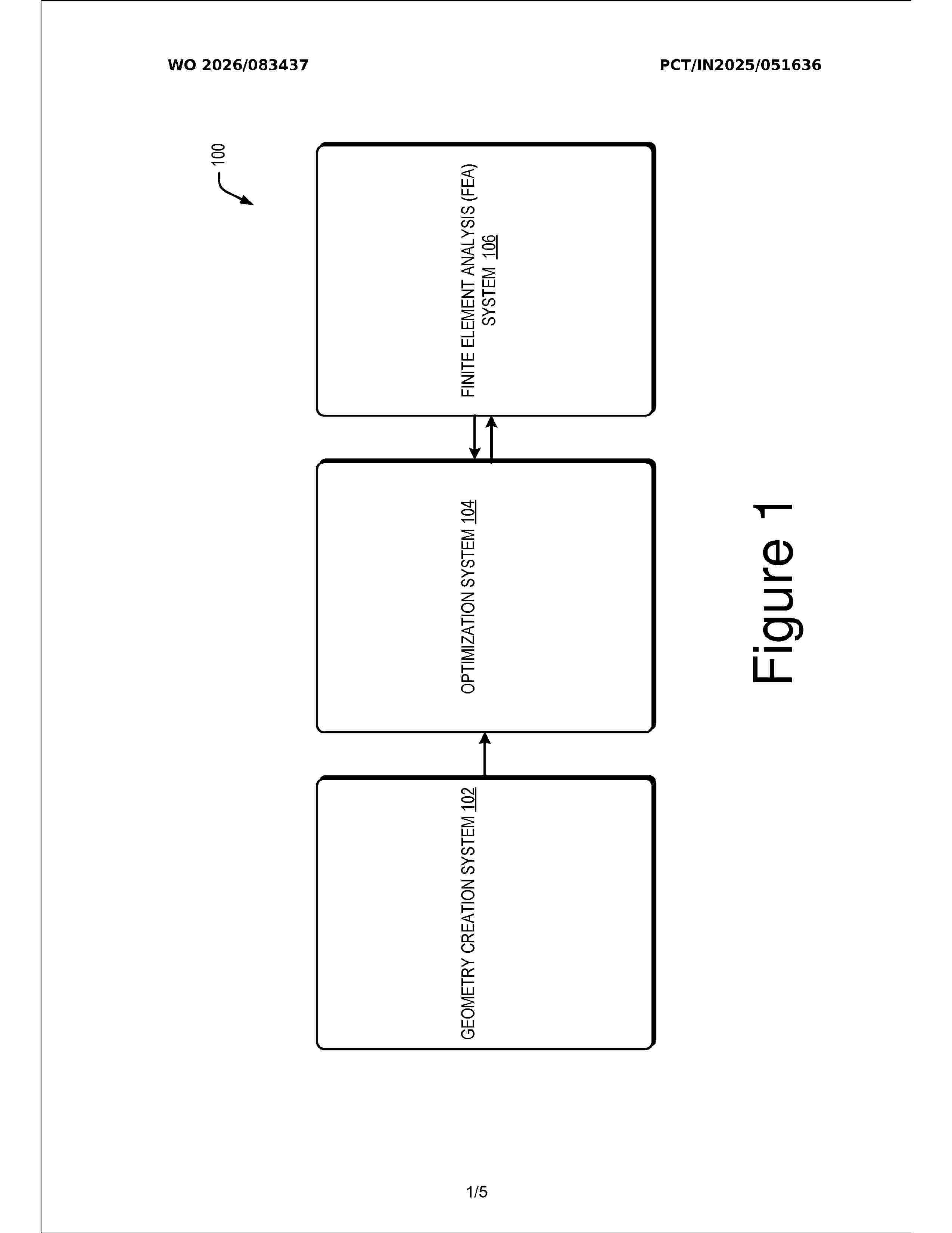
Resumen de: WO2026083437A1
The present relates to methods and systems for optimizing tower design The system (100) includes a geometry module (210) to receive from a user, input data comprising plurality of parameters to model an initial geometry of a tower indicative of one or more physical parameters. A load case generation module (212) is configured to generate load cases for testing the initial geometry. An iteration module (214) is configured to apply each load case to assess the initial geometry to withstand loads. Based on this assessment, a design alteration module (216) may sequentially alter at least one physical parameter of the initial geometry to obtain a plurality of tower designs. The load case generation module (212) determines a set of load cases corresponding to each design, which may be applied iteratively to the respective designs. An optimization analysis module (218) may identify an optimized design based on outputs corresponding to execution of the load cases on each of the plurality of designs.
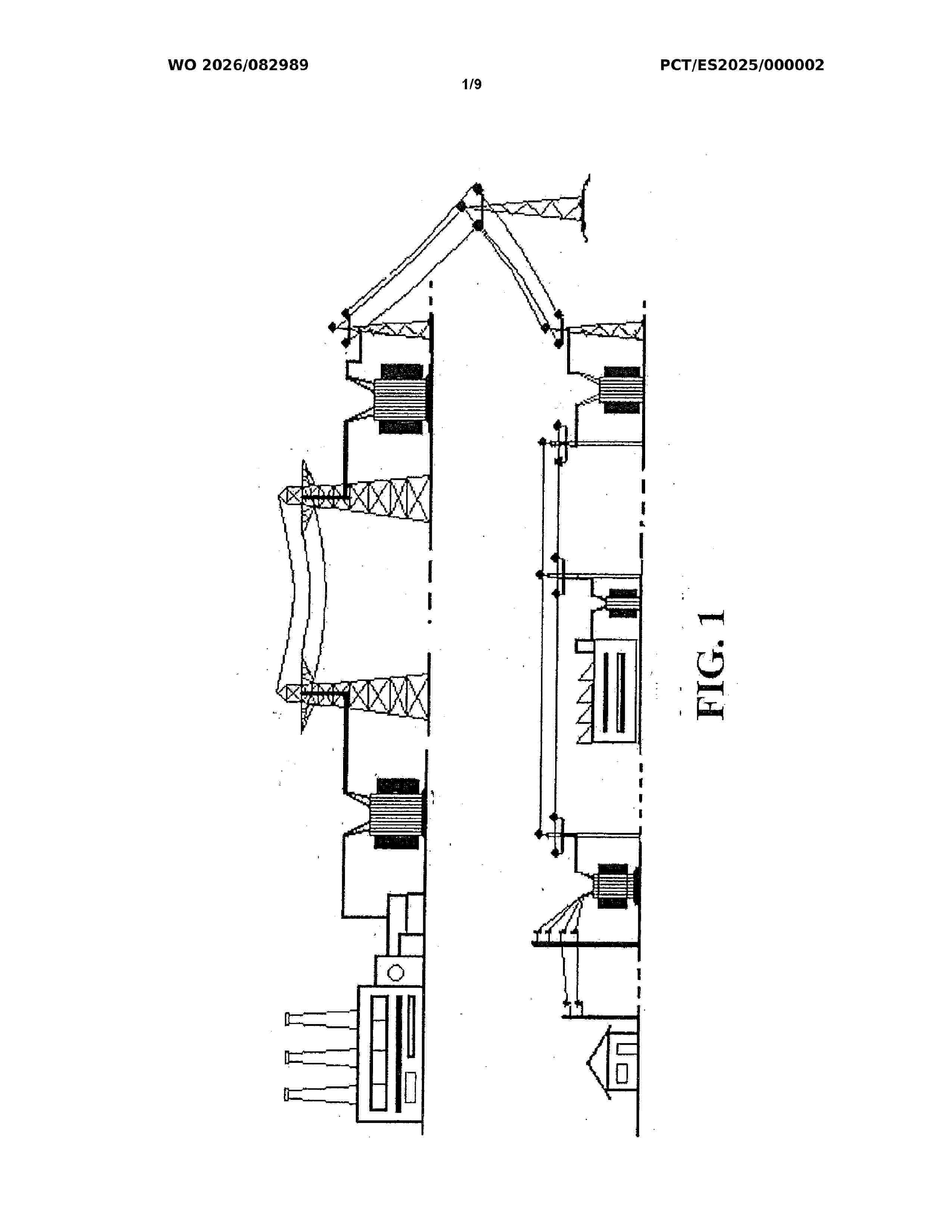
Resumen de: WO2026082989A1
The present invention relates to an energy transport system using pressurised fluids, comprising: pneumatic compressors or hydraulic pumps; fluid storage chambers or tanks at the discharge point and others at the receiving point; pipes for transporting or transferring the pressurised fluids; pressure sensors; fluid flow or pressure regulators and shut-off valves; multi-stage turbines actuated by the fluids, said turbines driving the electric generators or alternators; and a microprocessor controlling its operation. The materials used are stainless steels, reinforced concrete and corrosion-resistant plastic polymers, such as polyethylene. The compressors are driven mechanically or by means of electric motors powered by the power generators of wind turbines, water turbines or photovoltaic panels. The fluids used are carbon dioxide, ammonia, biofuels, synthetic fuels, natural gas, methane, biomethane, alcohols, water and mixtures thereof, and especially air.
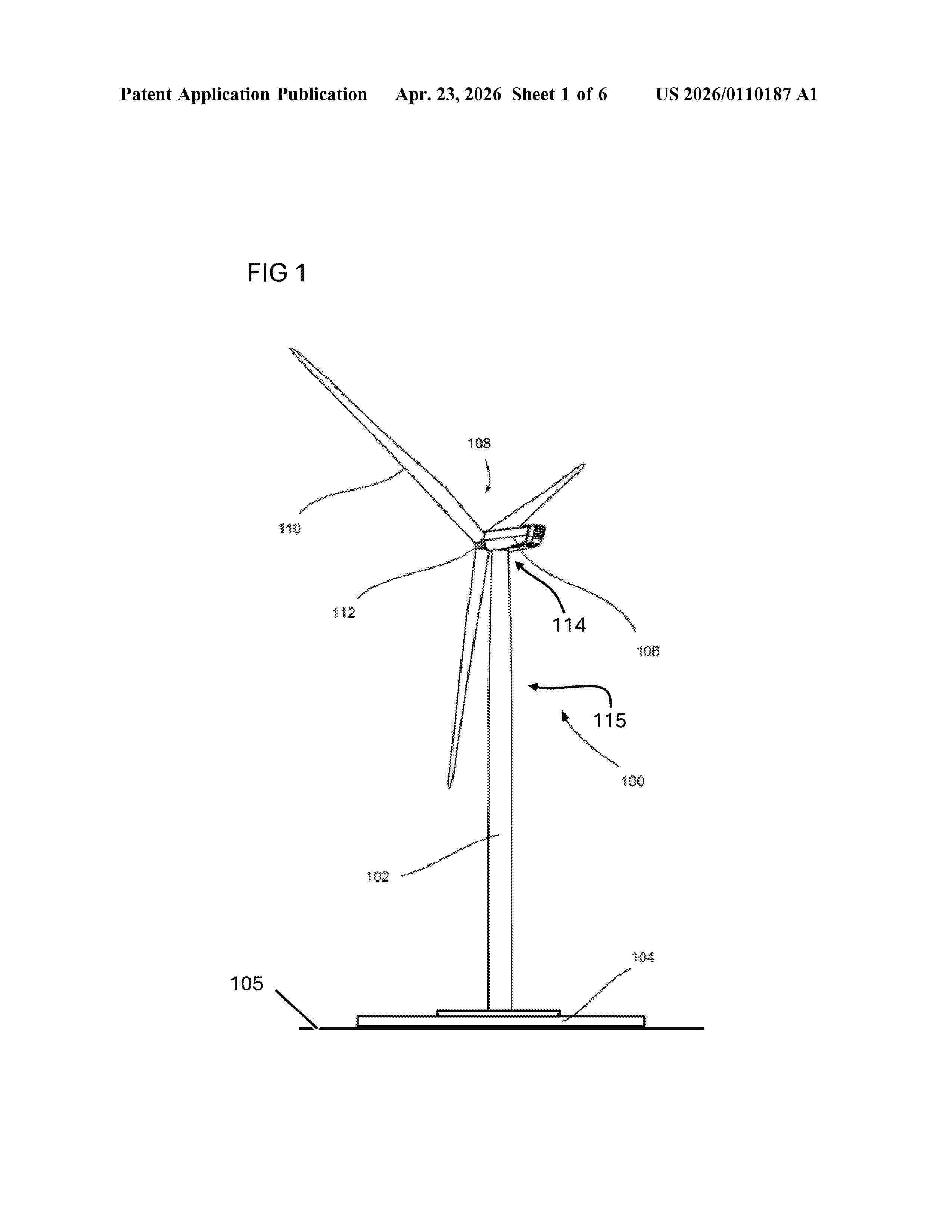
Resumen de: US20260110187A1
0000 In an embodiment a damping device includes a first rope configured to be connected to a tower and a first frame configured to be supported in a stationary manner on ground, to be coupled to the first rope, and to keep the first rope under tension.
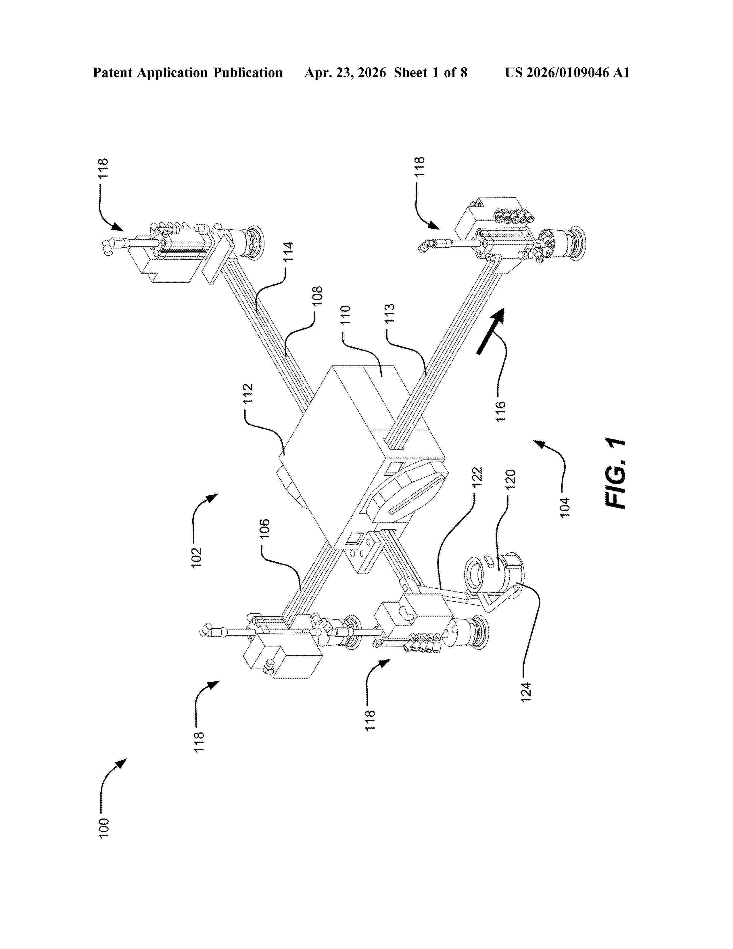
Resumen de: US20260109046A1
0000 Systems, methods, and devices include a robotic scanning device for performing a test scan on a target surface. The robotic scanning device has a sliding axis-based mobility system, which includes one or more slide rails slidably coupled together by a control housing. A first pair of actuatable coupling feet extend from the first slide rail; and a second pair of actuatable coupling feet extend from the second slide rail, thus forming a four-foot configuration. A scanning system disposed on the sliding axis-based mobility system can collect, receive, and transmit scanning information (e.g., ultrasonic data). Moreover, the robotic scanning device includes an integrated computing device including a control system operable to perform various mobility maneuvers. The mobility maneuvers can involve movements generated by controlled actuation of the sliding axis-based mobility system, causing the slide rails to move, and attaching and detaching the actuatable coupling feet to the target surface.
Resumen de: WO2026082177A1
Provided in the present disclosure are a method and system for controlling an active power of a wind power plant, and a device and a storage medium. The method comprises: performing first amplitude-limiting processing on an acquired initial active power target value, so as to obtain an active power reference value; acquiring a proportional control parameter and an integral control parameter of PI control on the basis of the active power reference value and an actual active power feedback value; performing anti-windup threshold parameter fuzzy adjustment on the basis of a response time and a response time variation between a current execution cycle and the execution cycle preceding the current execution cycle, so as to acquire an anti-windup threshold parameter; and performing PI control on an active power on the basis of the proportional control parameter, the integral control parameter and a current integral value, so as to acquire an active power given value. In the present disclosure, a control mode centered on an anti-windup threshold parameter fuzzy regulator and adaptive switching of an integral windup limit value is added on the basis of a PI controller, so as to realize active power anti-windup control for a wind power plant, and the occurrence frequency of integral windup of the PI controller is reduced by means of amplitude limiting processing, thereby optimizing the adaptive PI controller.
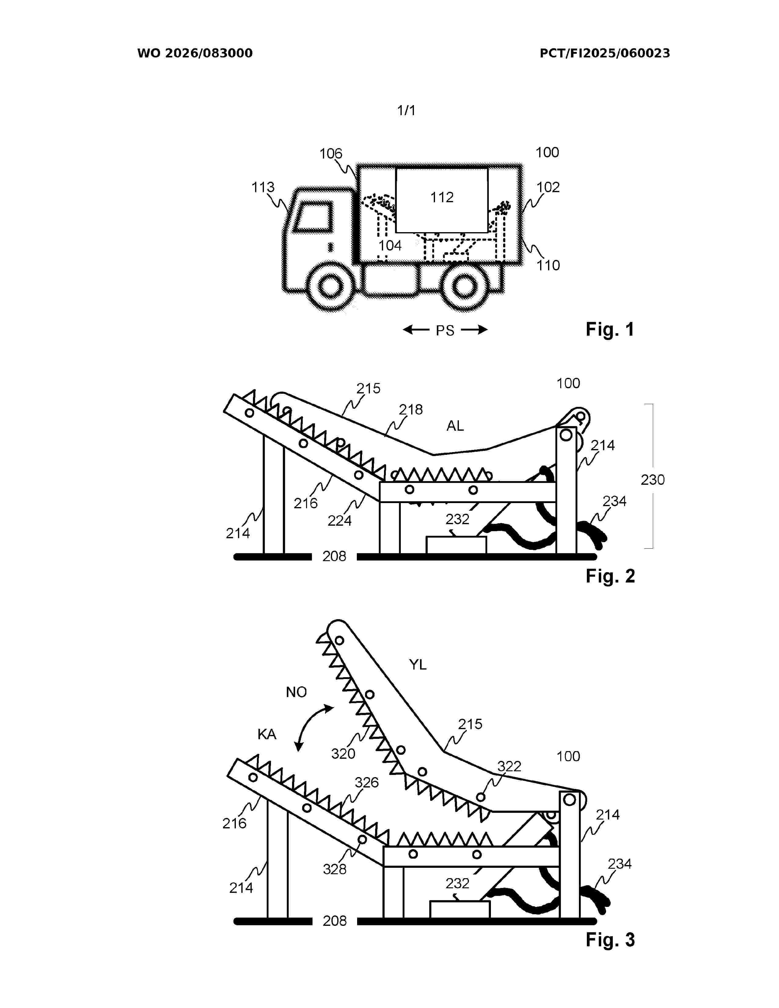
Resumen de: WO2026083000A1
The application relates to a crusher (100) for a rotor blade of a rotor of a wind turbine according to an embodiment. The crusher comprises a cutting blade (215), a cutting blade counter structure (216), and a power transmission system (230). The cutting blade is configured to move towards the counter structure so that the cutting blade moves in an overlapping manner with respect to the counter structure. The power transmission system is configured to move the cutting blade towards the counter structure to cut the interposed rotor blade and away from the counter structure. The crusher further comprises a protective container (102) that can be transported by a transport vehicle, designed to protect the cutting blade, the counter structure, and the power transmission system installed inside (104) the protective container, as well as to collect crushing waste generated during the crushing of the rotor blade.
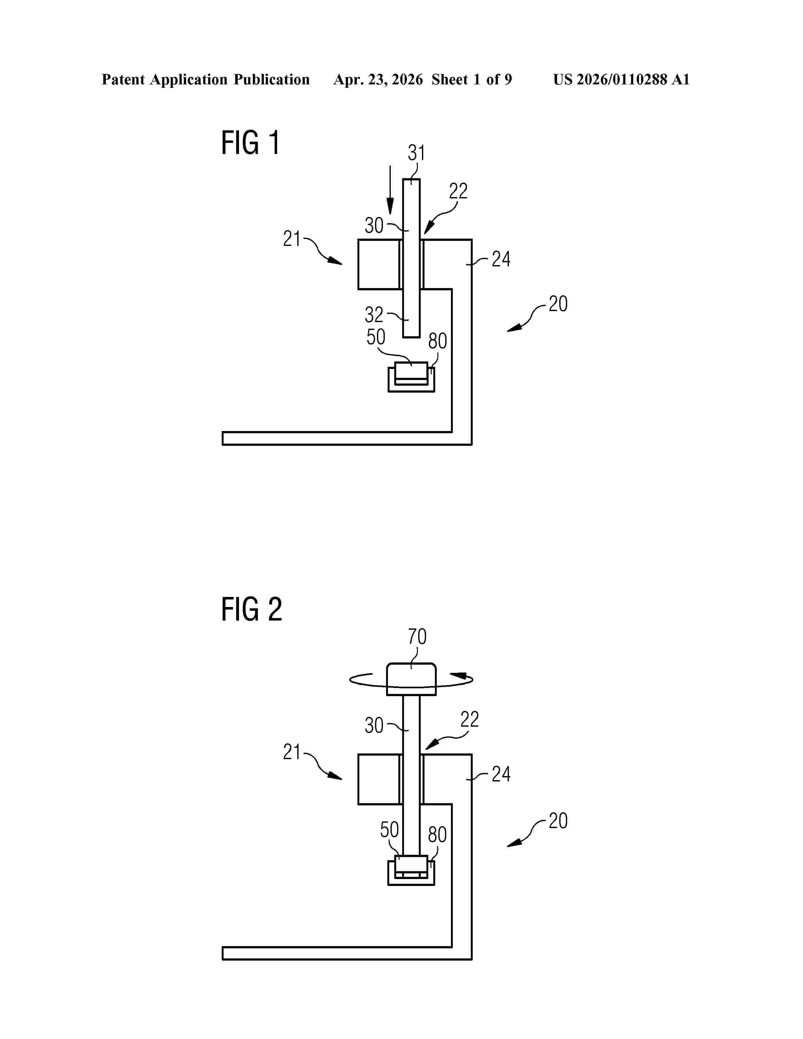
Resumen de: US20260110288A1
A method for installing a wind turbine tower is provided, wherein the tower includes a tower fastening portion and a tower through hole in the tower fastening portion, including: providing a vessel with a vessel fastening portion and a vessel through hole in the vessel fastening portion, landing the tower onto the vessel with the tower through hole at the vessel through hole, positioning a stud in the tower through hole and the vessel through hole, wherein the stud includes an upper portion protruding from the tower through hole in an upward direction and a lower portion protruding from the vessel through hole in a downward direction, fastening the tower fastening portion to the vessel fastening portion by a lower fastening element attached to the lower portion and an upper fastening element attached to the upper portion, wherein the lower fastening element and the upper fastening element are both detachable from the stud in a non-destructive way.
Resumen de: WO2026082996A1
The present disclosure relates to a rotor sail (100) comprising a rotor (110) having a lengthwise axis, an outer surface surrounding the lengthwise axis, a first end and a second end opposite to the first end, and the rotor having a first radius. A first end plate (114) is attached concentrically around the outer surface at the first end of the rotor. The first end plate includes a first circular edge having a second radius equal to the first radius of the rotor, a second circular edge having a third radius greater than the first radius, and a first slanted lateral surface extending between the first circular edge and the second circular edge, wherein the slanted lateral surface faces the second end and has an angle between 5 to 45 degrees in respect to a plane defined by the second circular edge.
Resumen de: US20260110353A1
A tooth for a toothed torque transmission assembly includes a tooth flank designed for torque exchange with a counter flank of a meshing partner. The tooth flank includes a periodically extending tooth flank correction including a sinusoidal corrugation having a locally extending period length T, wherein a development of the sinusoidal corrugation of the periodically extending tooth flank correction defines a center line. The periodic tooth flank correction is overlaid with a spatial microstructure having a local maxima and/or a local minima and a shortest distance t of t
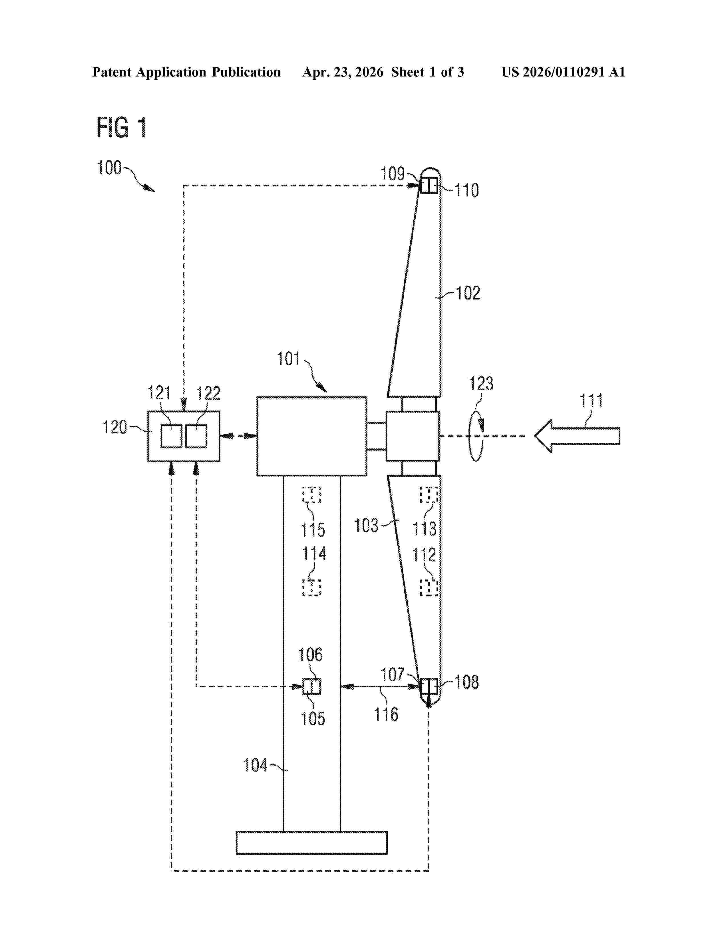
Resumen de: US20260110291A1
A method of estimating a position of at least a part of a rotor blade of a rotor of a wind turbine during operation of the wind turbine is provided. The rotor blade is deflected due to a deflection motion of the rotor blade towards a tower of the wind turbine and the position is indicative of the deflection. The method includes measuring a first parameter indicative of an absolute and/or a relative position of at least a second part of the rotor blade or of a further rotor blade of the rotor. The method further includes measuring second parameters indicative of an absolute and/or a relative position of at least a third part of the rotor blade or of the further rotor blade of the rotor. The method further includes estimating a state of the rotor blade and deriving the position from the estimated state of the rotor blade.
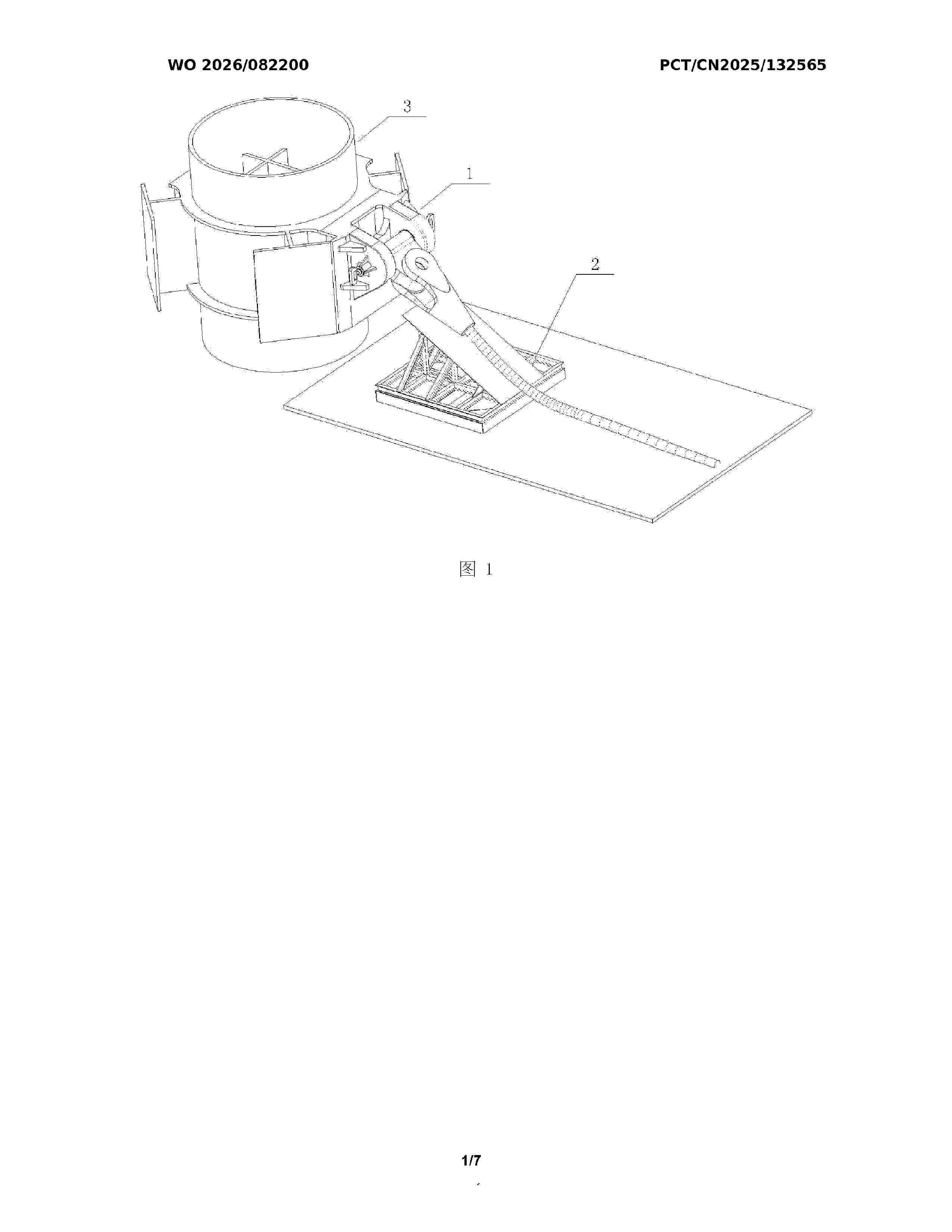
Resumen de: WO2026082200A1
The present invention relates to the technical field of mooring connection of tension-leg floating wind turbine platforms. Disclosed is a pile foundation connection device for a tension-leg floating wind turbine platform. The pile foundation connection device comprises a bottom connection mechanism and a steel cable protection mechanism, wherein the bottom connection mechanism comprises a welding back plate, a tongue plate is provided on the welding back plate, the upper end of the tongue plate is connected to a steel cable socket by means of a pin shaft, and a steel cable is connected to the steel cable socket, such that the steel cable is capable of two rotational degrees of freedom; both ends of the tongue plate are locked and fixed by means of locking mechanisms; and the steel cable protection mechanism is located on one side of a pile foundation, and the steel cable is placed on the steel cable protection mechanism after the steel cable is connected, so as to prevent over-bending damage to the steel cable when same is pre-laid on the seabed. The present invention features a simple structure, a reliable performance and convenient operation, and can adapt to underwater quick connection; and the entire operation process only requires the assistance of one ROV, thereby simplifying the tie-back installation procedure of mooring lines and anchoring devices for a tension-leg wind turbine platform, and reducing the mooring and installation costs of the tension-leg wind turbine p
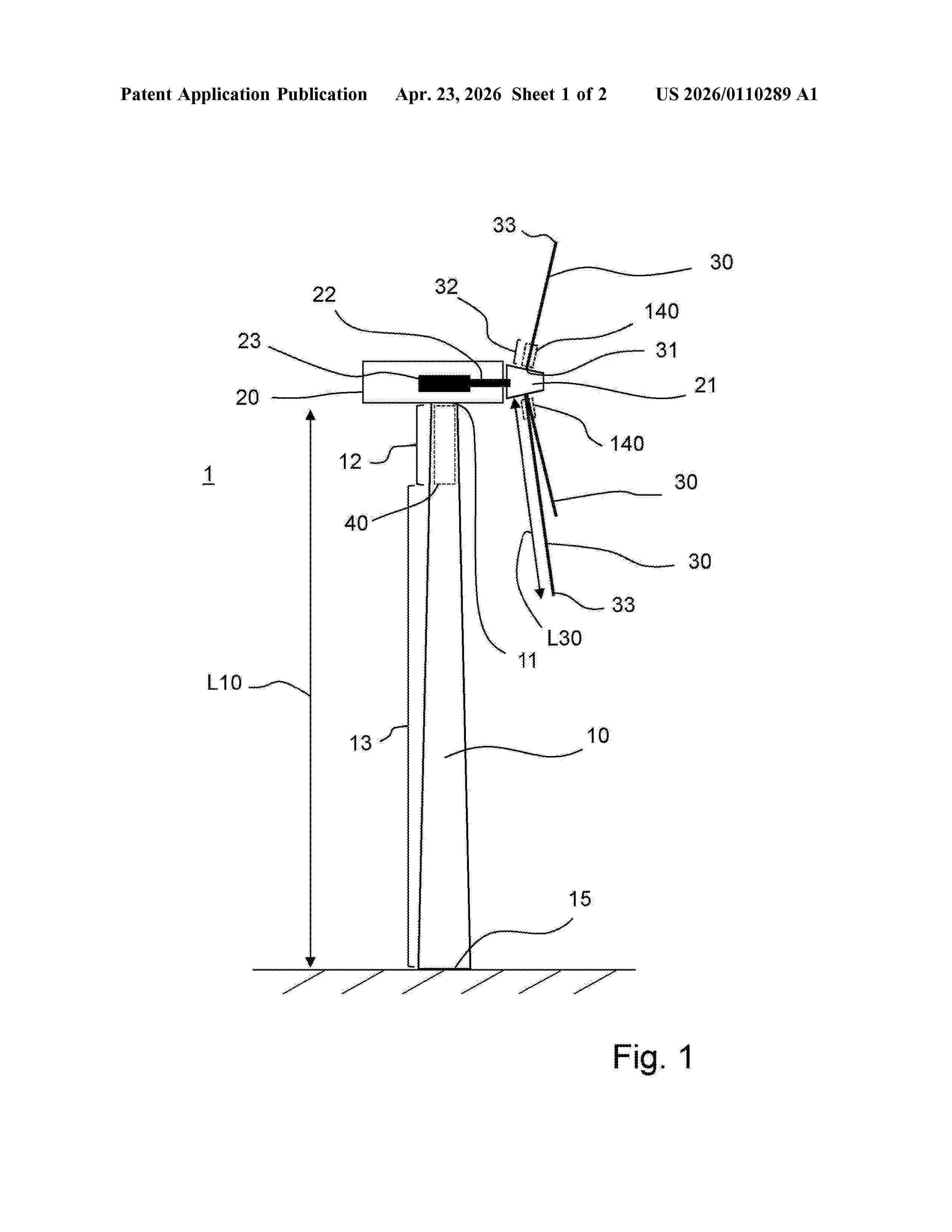
Resumen de: US20260110289A1
0000 The invention relates to a vibration damper assembly (40; 140) for an elongate first component (10; 30), which is arranged at a connecting end (11; 31) in a longitudinal direction (LD) of the first component (10; 30) for mechanical connection to a second component (20). The vibration damper assembly (40; 140) comprises at least two damper groups (41a, 41b, 41c, 41d, 41e ) which are arranged in an end section (12; 32) of the first component (10; 30) with the connection end (11; 31) and are spaced apart from one another in the longitudinal direction (LD), wherein each of the damper groups (41a, 41b, 41c, 41d, 41e ) comprises a plurality of individual vibration dampers (42a, 42b, 42c, 42d, 42e ) which are arranged distributed on a circumferential wall (14) of the first component (10; 30) in a circumferential direction (CD). In order to reduce the problems caused by tonalities in wind energy installations (1) in a simple and cost-effective way, the damper groups have different natural frequencies from each other. The invention also relates to a wind energy installation (1).
Resumen de: WO2026082993A1
The invention relates to an improved barrel and bolt connecting device, the purpose of which is to reduce the bending moment generated in the T-bolt connection by means of both components, with the structure of the two parts combining to enhance the connection under high bending loading and, in this way, the durability and performance of the connection are increased.
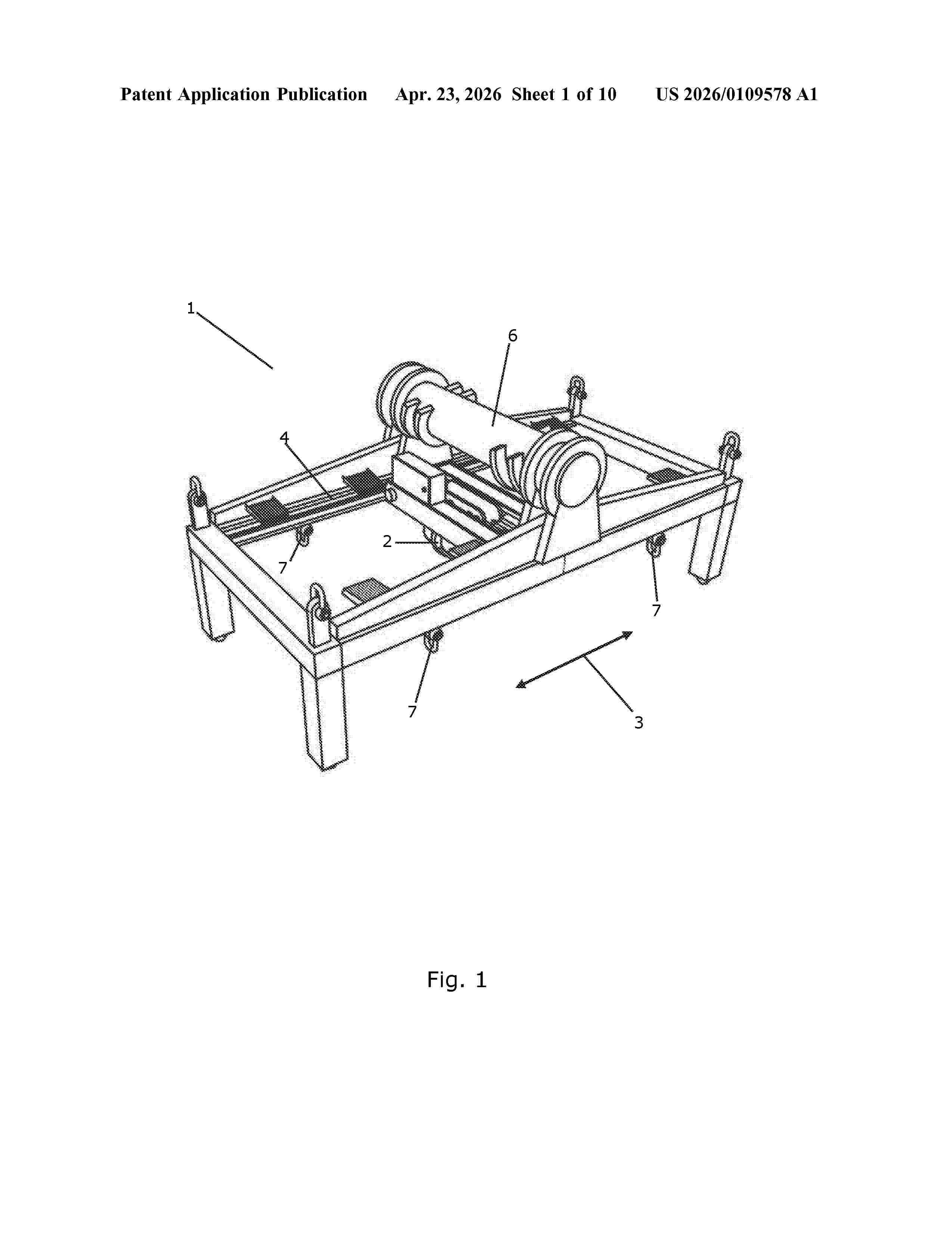
Resumen de: US20260109578A1
A lifting arrangement for installing and uninstalling a component (16) of a wind turbine (15) is disclosed. The lifting arrangement comprises main yoke (1) being configured to be attached to a main crane (25), and a hoisting mechanism (2, 11) attached to the main yoke (1). The hoisting mechanism (2, 11) is configured to have a component (16) to be installed or uninstalled attached thereto and to move the component (16) relative to the main yoke (1). At least one connecting part (12) is each configured to establish 2024/067929 a pretensioned connection between the main yoke (1) and a nacelle (14) of the wind turbine (15). The pretension of the at least one connecting part (12) is provided by operating a main crane (25) having the main yoke (1) attached thereto. Methods for installing and uninstalling a component (16) in a nacelle (14), using the lifting arrangement, are also disclosed.
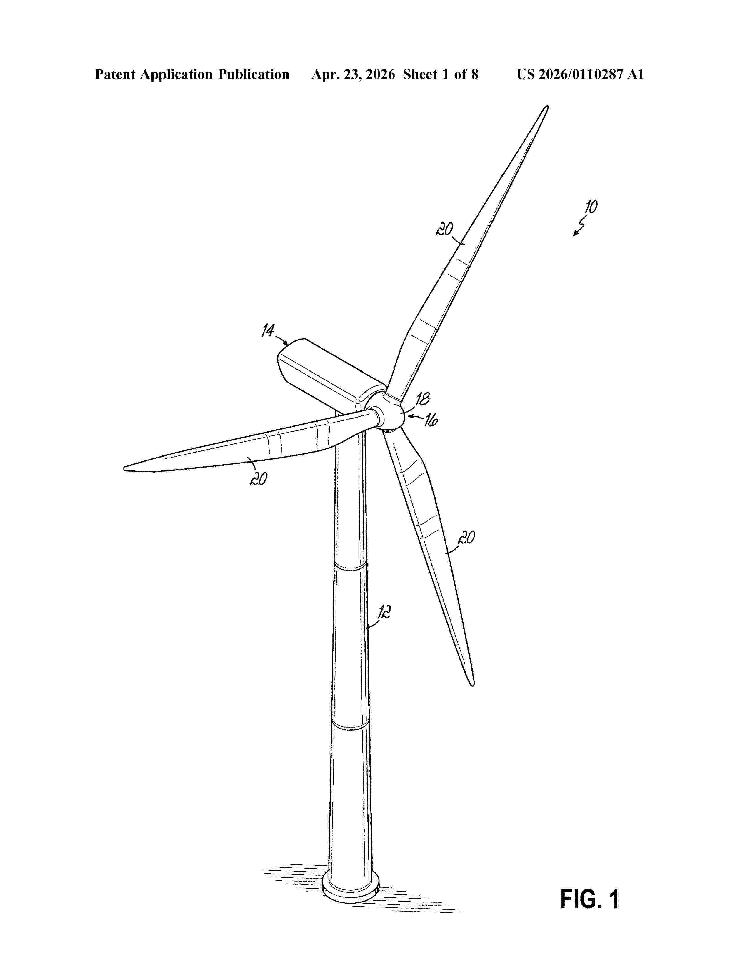
Resumen de: US20260110287A1
0000 A robotic applicator device (40) for applying a protector (48) to a leading edge (30) of a wind turbine blade (20) includes a main frame (42), a drive (44) coupled to the main frame (42), and a plurality of stations (46) carried by the main frame (42) configured to apply the protector (48) to the leading edge (30) of the wind turbine blade (20). The stations (46) include a dispensing station (50) configured to hold and dispense a material (64) that forms the protector (48), an adhesive station (52) configured to apply adhesive (66) to an adherend surface (68) of the dispensed protector material (64) and/or the leading edge (30), an applicator station (54) configured to place the adherend surface (68) of the protector (48) onto the leading edge (30) of the wind turbine blade (20), and a curing station (56) configured to cure the adhesive (66) so as to bond the protector (48) to the leading edge (30). A method for applying the protector (48) to the leading edge (30) of the wind turbine blade (20) is also disclosed.
Resumen de: AU2024361768A1
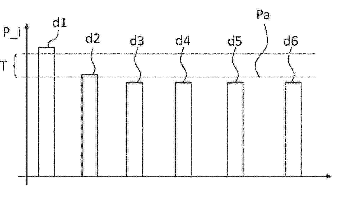
According to an embodiment, the method is for operating a wind turbine (100) having a rotatable component (1 to 4) and N drives (di) for rotating the rotatable component by exerting torques, wherein N ≥ 2. The method comprises a step of providing first information (I1) which is representative of at least one operation parameter (P_i) of each drive. In a further step, second information (I2) is determined depending on the first information. The second information is representative of an operation parameter average (Pa, Pa_I, Pa_II) averaged over at least two drives. Third information (I3) is determined depending on the first and the second information, wherein the third information is representative of whether the operation parameter of at least one drive differs from the operation parameter average by more than a defined threshold (T). If this is the case, a first measure (M1) is executed. The first measure is configured to cause maintenance of the at least one drive. Additionally or alternatively, the first measure is configured to cause a change of the operation of the wind turbine.
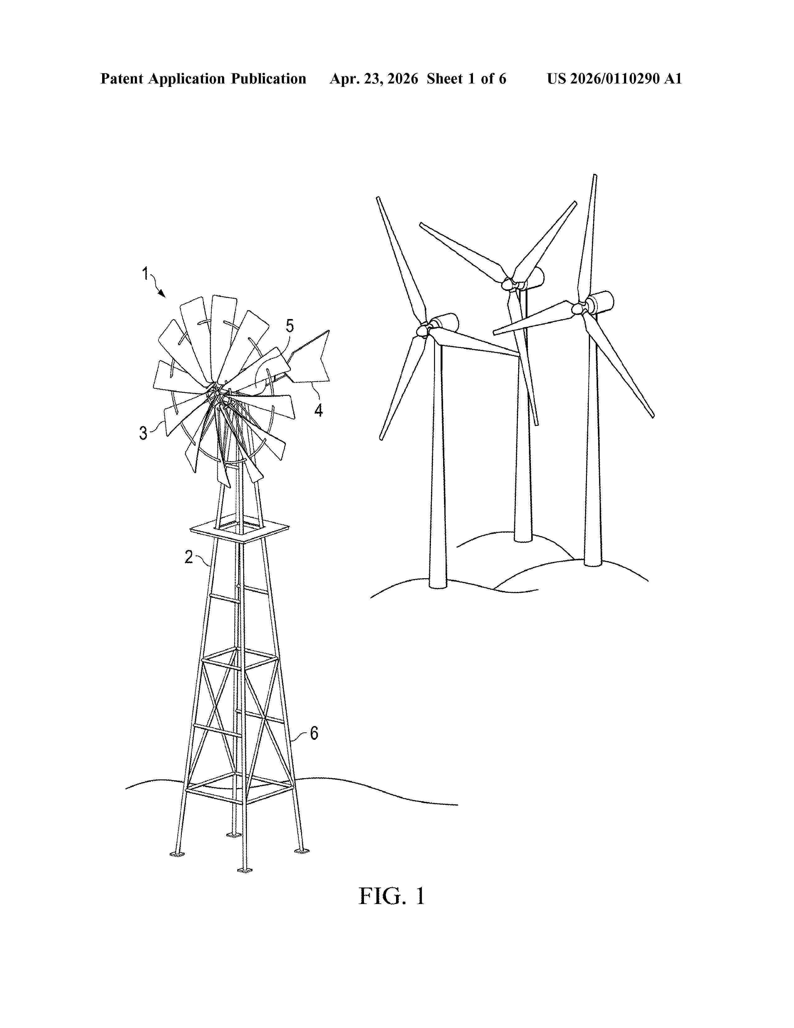
Resumen de: US20260110290A1
A wind-based power generation system includes a windmill having a wheel assembly, a gearbox coupled to the wheel assembly and configured to convert rotational motion of the wheel assembly into a reciprocal motion, and a shaft coupled to the gearbox and driven in a reciprocal motion. The wind-based power generation system also includes a crank system comprising a linkage and a pitman arm, the linkage and pitman arm configured to convert the reciprocal motion of the shaft into a rotational motion that drive a generator to produce electric power that may be used or stored.
Resumen de: WO2026083343A1
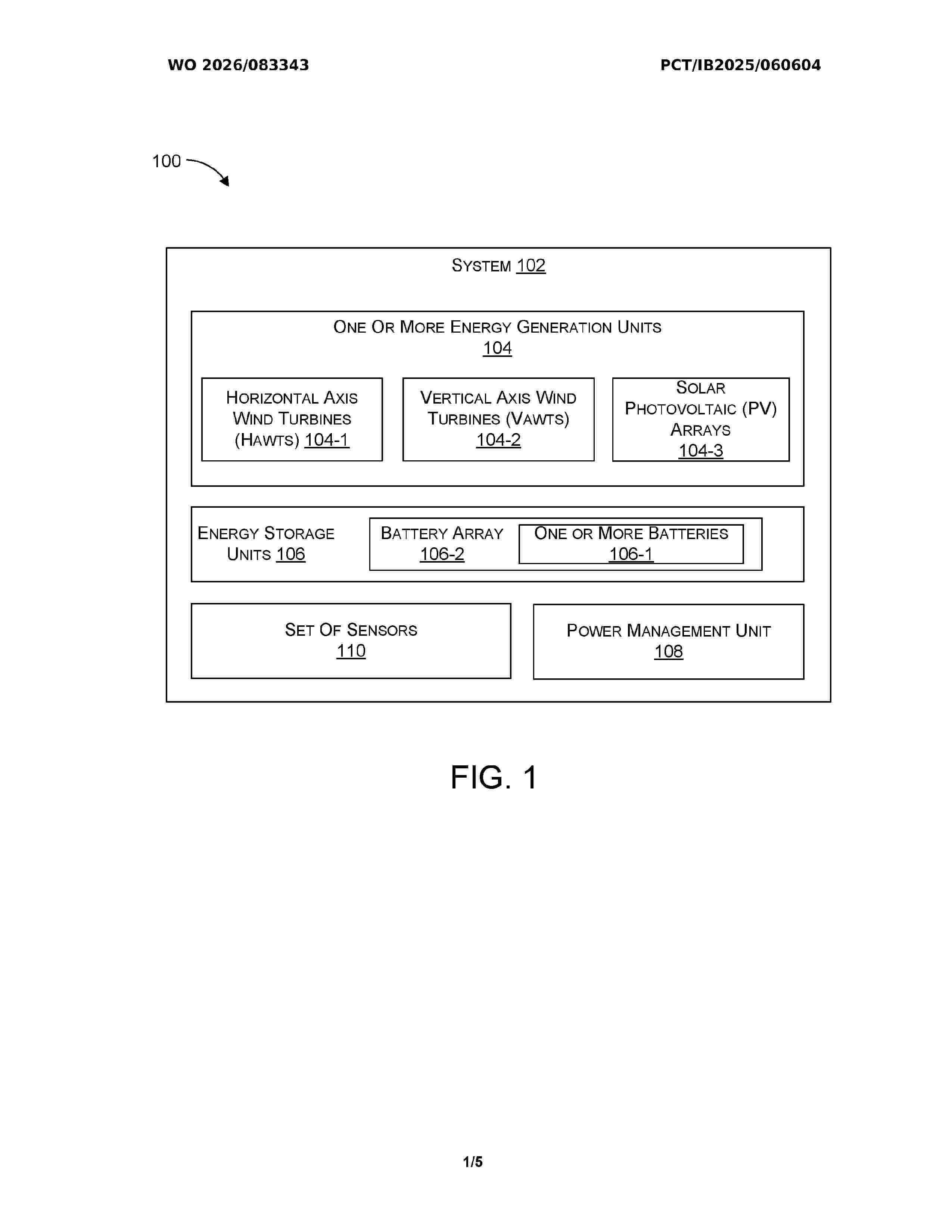
The present disclosure discloses a system (102) and a method (200) for generating electrical energy from one or more renewable energy sources. The system (102) includes one or more energy generation units (104) having one or more horizontal axis wind turbines (HAWTs) (104-1) mounted at a predetermined location to capture wind energy, and one or more vertical axis wind turbines (VAWTs) (104-2) positioned in proximity of the HAWTs (104-1) to harness generated wind energy and environmental wind currents for producing electrical energy. The system (102) further includes one or more solar photovoltaic (PV) arrays (104-3) configured to receive solar energy and convert it into electrical energy. One or more energy storage units (106) are operatively coupled to store the generated electrical energy. A power management unit (108) regulates the flow of stored electrical energy and facilitates its utilization for one or more energy utilization tasks.
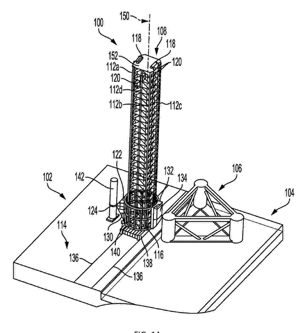
Resumen de: EP4729768A1
A carousel lifting tower may facilitate assembly of a wind turbine generator (WTG) and other constructs. In one example, the carousel lifting tower includes a tower, which may be positioned in an upwardly angled orientation, and which may define a tower axis. In the example, the carousel lifting tower further includes a lift frame, which may be movably mounted on the tower to allow translation of the lift frame along the tower axis. Additionally, in the example, the carousel lifting tower includes a carousel coupled to the lift frame. The carousel may rotate about the tower axis. Moreover, in the example, the carousel lifting tower includes a load handler on the carousel. The load handler may releasably engage with a component to be lifted.
Resumen de: EP4502370A1
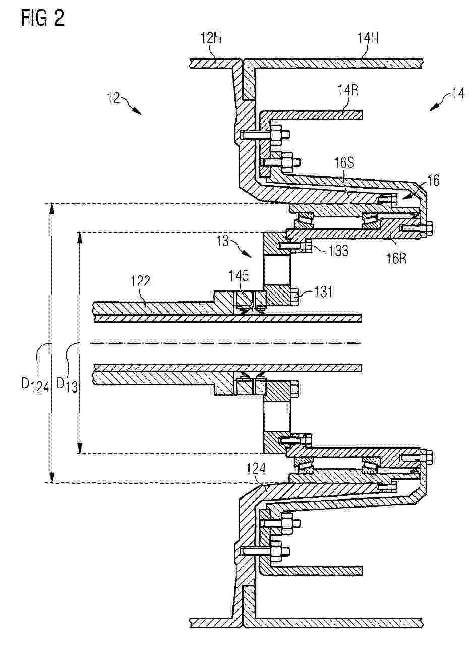
The invention describes a wind turbine drivetrain (1) comprising a planetary gearbox (12) for converting rotation of a low-speed shaft (10) to rotation of a high-speed gearbox output shaft (122); a generator (14) mounted about an annular sleeve (124) extending axially outward from a gearbox housing (12H) and enclosing the gearbox output shaft (122); a bearing assembly (16) arranged between the generator (14) and the gearbox (12), comprising a rotary bearing part (16R) and a stationary bearing part (16S); and a torsional vibration damper (13) arranged between two rotary components (122, 122A, 122B, 14R, 16R) of the drivetrain (1), which torsional vibration damper (13) comprises a number of damping elements (13E). The wind turbine drivetrain is characterized in that the torsional vibration damper (13) is dimensioned to facilitate access from within the generator (14). The invention further describes a method of performing a maintenance procedure on such a wind turbine drivetrain (1).
Resumen de: EP4729767A1
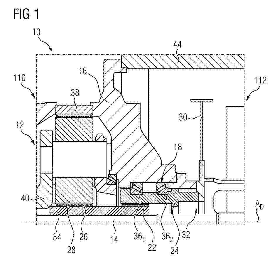
0001 Komponentenschnittstelle 10 zwischen einer Getriebeeinheit 110 und einer Generatoreinheit 112 für eine um eine Triebstrangachse A
Nº publicación: EP4729766A1 22/04/2026
Solicitante:
ROESSLER JOCHEN [DE]
Resumen de: EP4729766A1
0001 Ein Verfahren zur Bestimmung von Betriebszuständen einer Windenergieanlage (2) umfasst das Bereitstellen eines Kl-Modells (10), wobei das Kl-Modell 10 trainierbar ist, um auf der Basis von eingelesenen Daten, die aktuelle und/oder künftige Umweltparameter (11a) und/oder Regeldaten (12a) beinhalteten, zumindest einen aktuellen und/oder künftigen Betriebszustand der Windenergieanlage (2) zu bestimmen, das Bestimmen des zumindest einen aktuellen und/oder zukünftigen Betriebszustandes (13) der Windenergieanlage (2) mithilfe des KI-Modells (10) auf Basis der eingelesenen Umweltparametern (11a) und/oder Regeldaten (12a).
 BOPI
BOPI
 Sede Electrónica