Si deseas distinguir tus productos, servicios o ambos de los de otra empresa, es posible que necesites una marca o nombre comercial. Descubre qué son, en qué consiste su procedimiento de registro y qué implica.

Información sobre los plazos de presentación de solicitudes de transformación de marcas de la Unión Europea en marca nacional española. Más información


Si tienes un nuevo dispositivo, producto o procedimiento que resuelva un problema técnico o tenga una ventaja práctica, existen distintas formas de protegerlo en España y en otros países. Descubre cómo hacerlo.

¿Tu innovación reside en la estética, la ornamentación o la apariencia de tu producto? Protégela mediante un diseño industrial. Descubre qué derechos confiere el registro y cómo realizar la tramitación.

Las indicaciones geográficas protegen el nombre de un producto originario de una zona geográfica, a la cual le debe una determinada calidad, reputación u otra característica. Descubre qué son, en qué consiste su procedimiento de registro y qué beneficios conceden.

Las patentes publicadas en todo el mundo son una valiosa fuente de información científica, técnica y comercial.

Si eres emprendedor/a o una empresa y quieres potenciar y mejorar la rentabilidad de tu negocio protegiendo de forma adecuada los activos intangibles de tu organización, en este espacio encontrarás lo necesario.


 568
resultados
568
resultados
 Última actualización
04/04/2026 [07:17:00]
Última actualización
04/04/2026 [07:17:00]


 Resultados 350 a 375 de 568

Resumen de: DE102025138556A1
Eine Winden-Vorrichtung (5) für eine Windkraftanlage (2) weist eine Tragstruktur (33) mit einem ersten Tragstruktur-Element mit einer Aufnahme-Einrichtung zur Aufnahme einer sich entlang einer Längsrichtung erstreckenden Start-Einrichtung (6) für ein Fluggerät, eine erste Trommel zum Aufwickeln eines mit einem Fluggerät verbundenen Zugmittels, welche um eine erste Drehachse drehbar gelagert ist, und eine zweite Trommel zum Aufwickeln eines mit einem Fluggerät verbundenen Zugmittels, welche um eine zweite Drehachse drehbar gelagert ist, auf wobei die Drehachsen der Trommeln ortsfest relativ zur Aufnahme-Einrichtung (8) angeordnet sind.

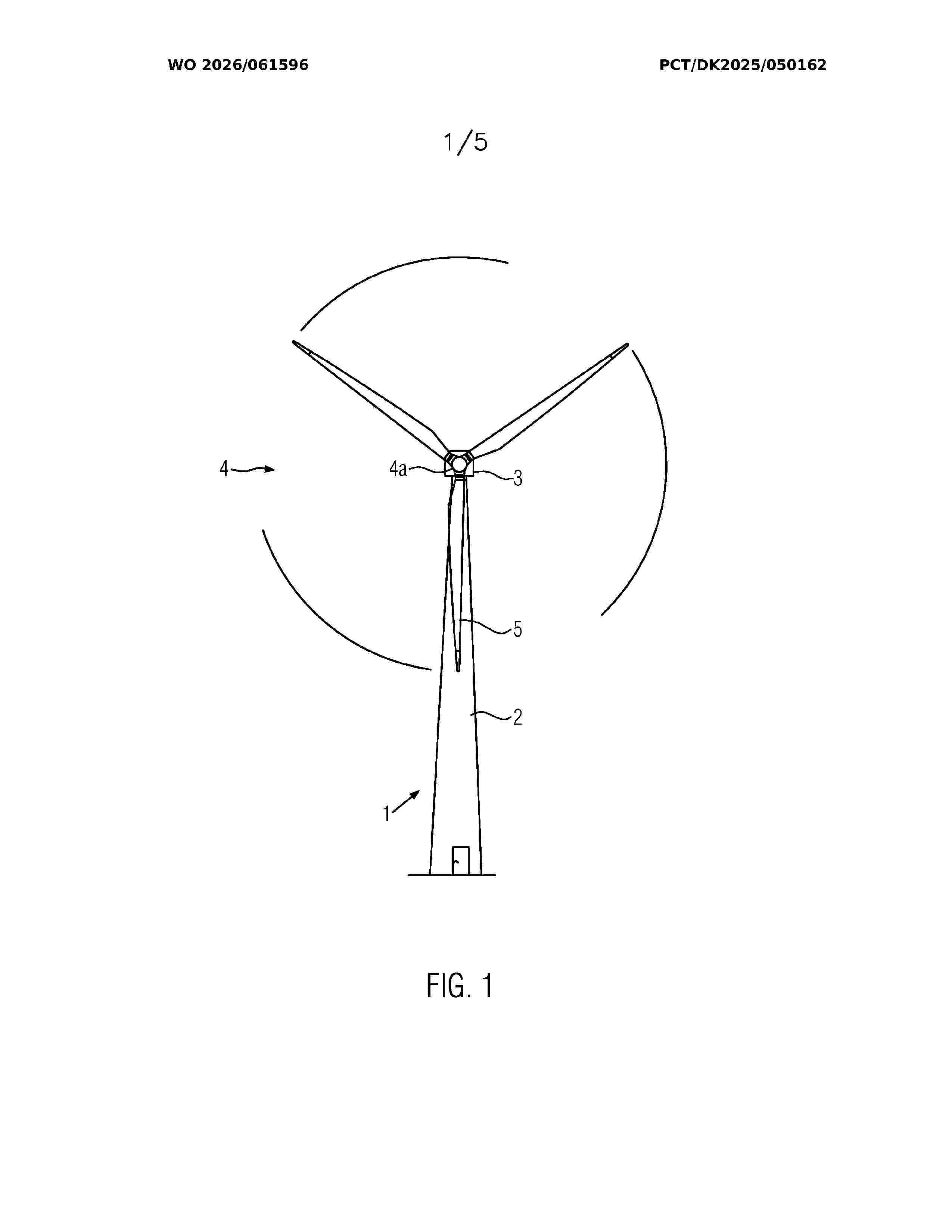
Resumen de: WO2026061596A1
The present invention relates to a lightning current transfer unit for a wind turbine comprising: at least two contact means configured to connect two components of the wind turbine configured to rotate with respect to each other; and at least one electric conductor establishing an electrical connection between the at least two contact means, wherein the contact means and the electric conductor form a rolling bearing having a gear structure The present invention also relates to a wind turbine comprising one or more of such lightning current transfer units.
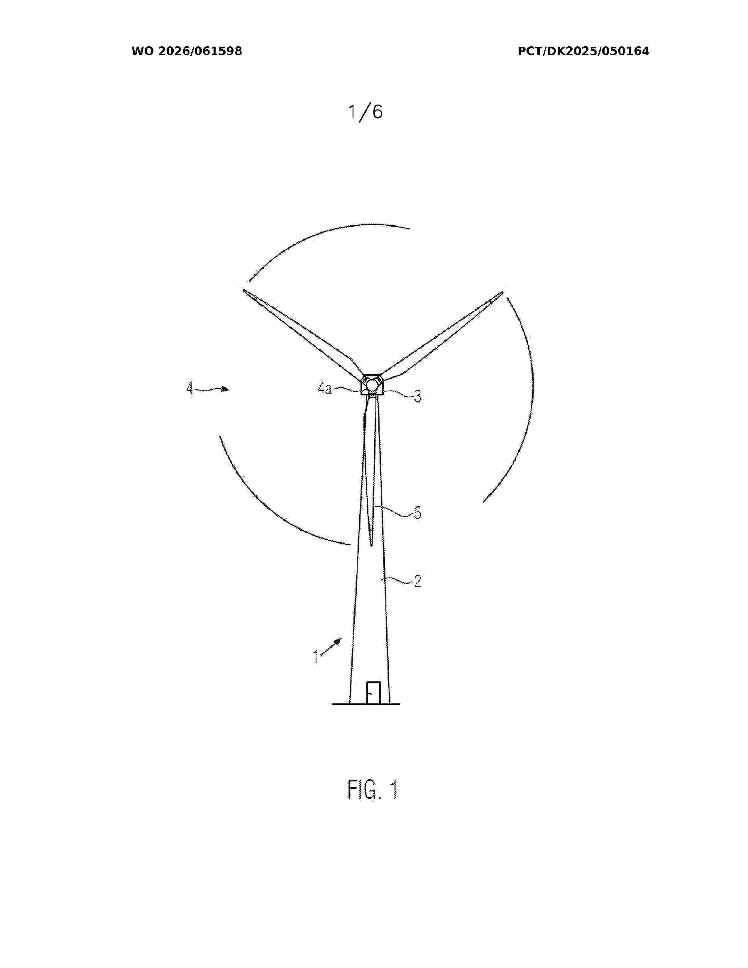
Resumen de: WO2026061598A1
The present invention refers to a wind turbine comprising a tower, a nacelle mounted on the tower and a rotor connected to the nacelle, wherein the rotor comprising a rotor hub and a plurality of blades connected to the rotor hub, and the rotor hub is coupled to a main shaft which is rotatably supported in the nacelle by a bearing arrangement According to the invention, the wind turbine further comprises a plurality of lightning current transfer systems, each lightning current transfer system being coupled to a corresponding blade and comprising a down conductor extending between a first end and a second end, wherein the down conductor extends at least within a root portion of the corresponding blade, within the rotor hub and the main shaft, and the down conductor is guided from an interior to an exterior of the main shaft. The first end of the down conductor is located at the exterior of the main shaft and is coupled with a first contact element that is configured to provide an electrical connection with a second contact element connected to the nacelle, in such a way that, lightning current can be transferred from the corresponding blade to the second contact element by means of the down conductor.
Resumen de: WO2026061597A1
The present invention relates to a lightning current transfer unit for a wind turbine comprising a conductive element suitable for coupling the lightning current transfer unit to a first component of the wind turbine, a pair of sliding-contact pads biased against the conductive element and towards each other so as to clamp the conductive element, and one or more electric conductors electrically connected to the pair of sliding-contact pads The conductive element has a ring-shape with a central axis and is arranged in such a way that its central axis coincides with the axis of rotation of the first component on which is mounted with respect to a second component of the wind turbine that is rotatably connected to the first component. Moreover, the conductive element has a first surface and a second surface, opposite to the first surface, and a first sliding-contact pad is configured to establish a sliding electrical connection with the first surface and a second sliding-contact pad is configured to establish a sliding electrical connection with the second surface during the rotation. In the lightning current transfer unit according to the invention, lightning current can be transferred between the conductive element and the one or more electric conductors via the sliding-contact pads. The present invention also refers to a wind turbine comprising such a lightning current transfer unit.
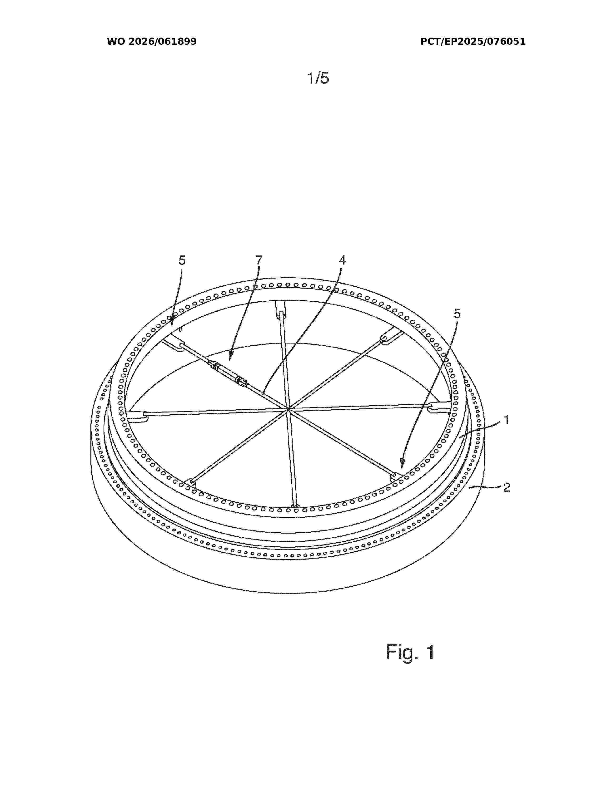
Resumen de: WO2026061899A1
The present invention relates to a blade bearing for mounting a rotor blade of a wind turbine on a hub, the blade bearing comprising an inner ring element (1) and an outer ring (2) which is arranged concentrically to the inner ring element (1). In order to provide such a blade bearing which has high rigidity, and thus high deformation resistance, and is at the same time light-weight, at least one tension element (4) is attached to an inner lateral surface (3) of the inner ring element (1), the at least one tension element (4) allowing mutually opposing tensile forces to be applied to the inner ring element (1) at at least two opposite points of application (5).
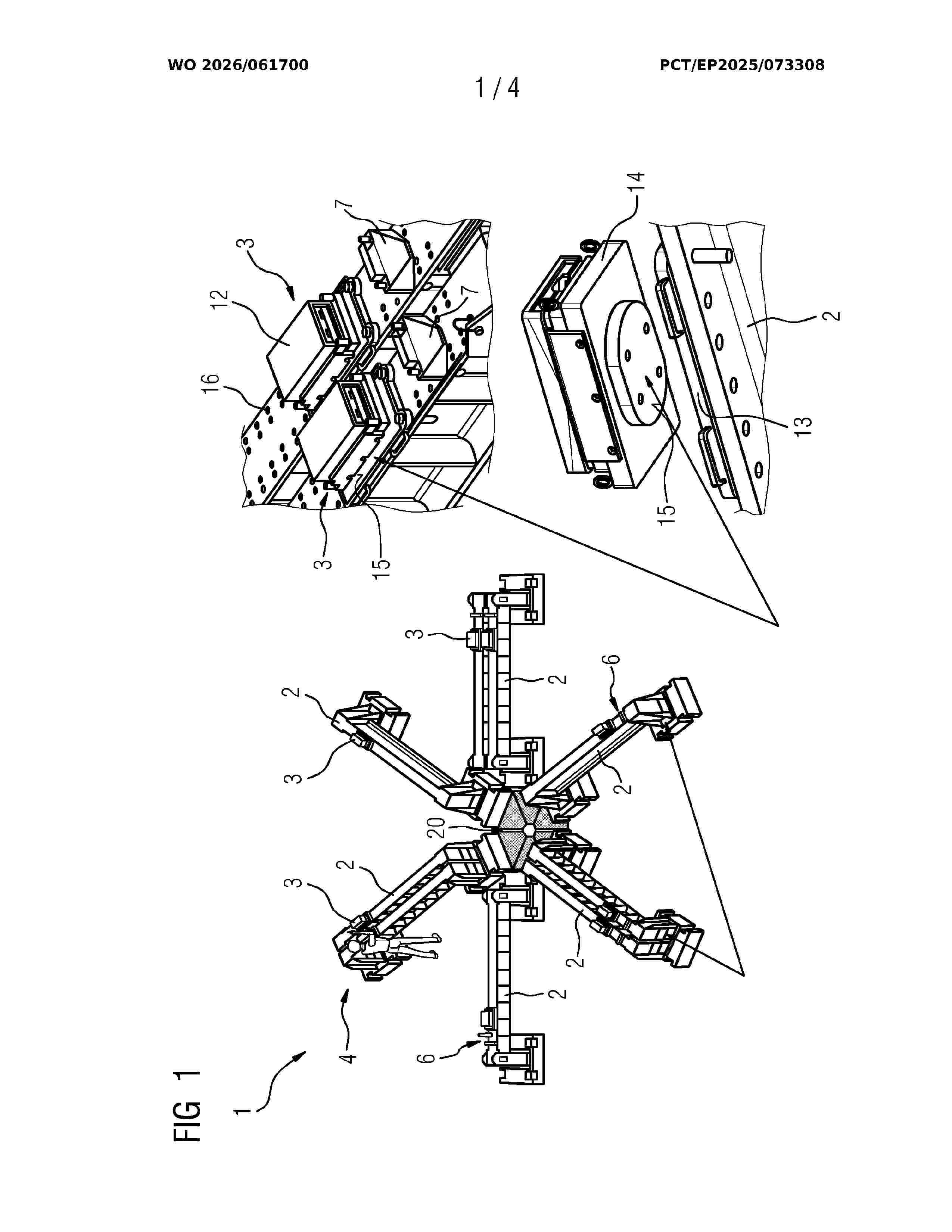
Resumen de: WO2026061700A1
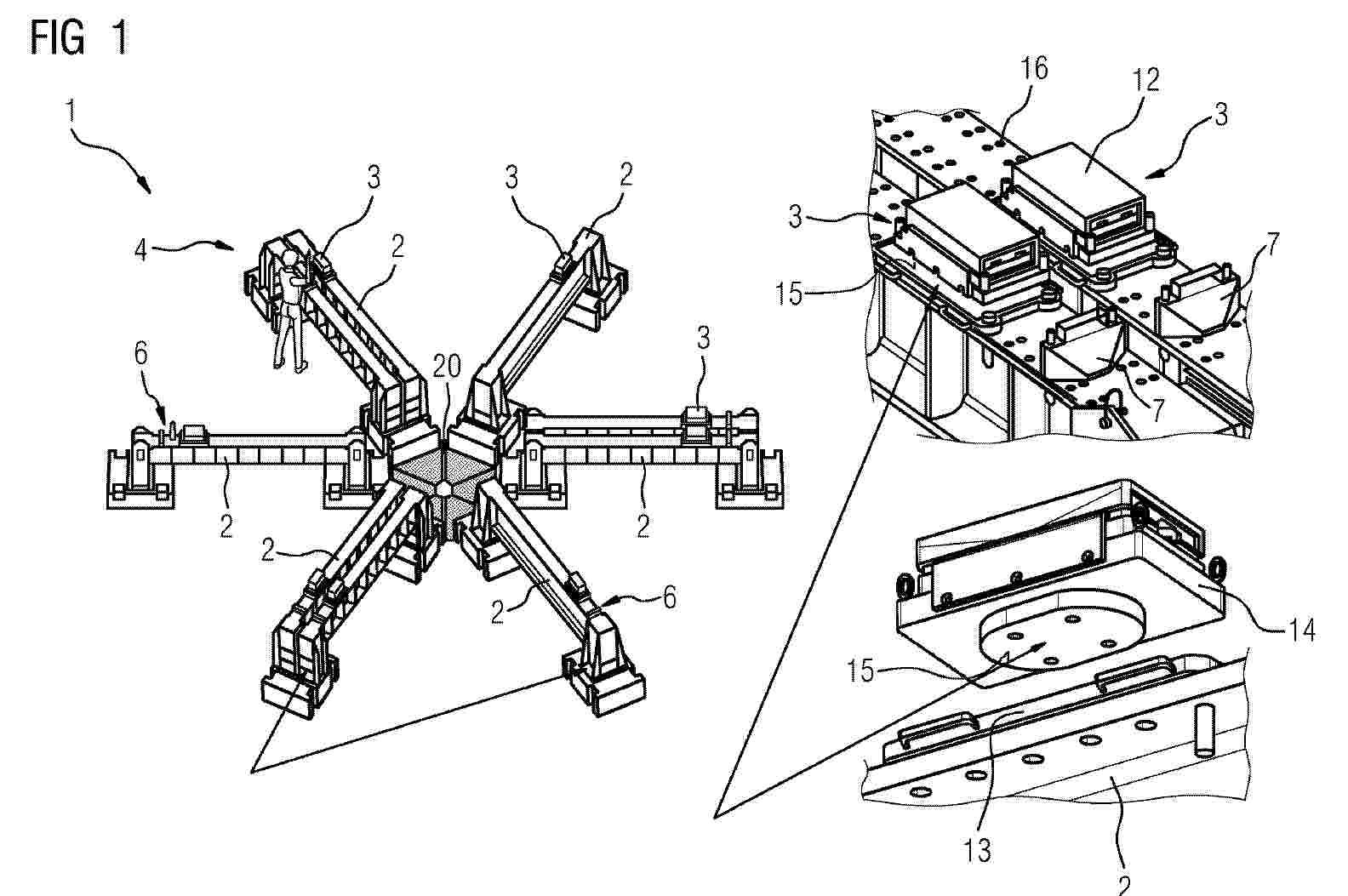
An assembly stand (1) and associated method for assembling a concrete ring (11) from a plurality of concrete segments (10), the assembly stand (1) comprising a plurality of beams (2) configured to support the concrete segments during their assembly into the concrete ring, in particular the beams mounted with a star configuration from the central axis, a movement mechanism (3) mounted on one or of more of the plurality of beams (2), in particular mounted on all beams (2), wherein each movement mechanism (3) is configured to contact or engage with an underside of the concrete segments (10) and to allow a controlled movement of the concrete segments (10) relative to the beam (2) when an assembly force (F) is applied.
Resumen de: WO2026062124A1
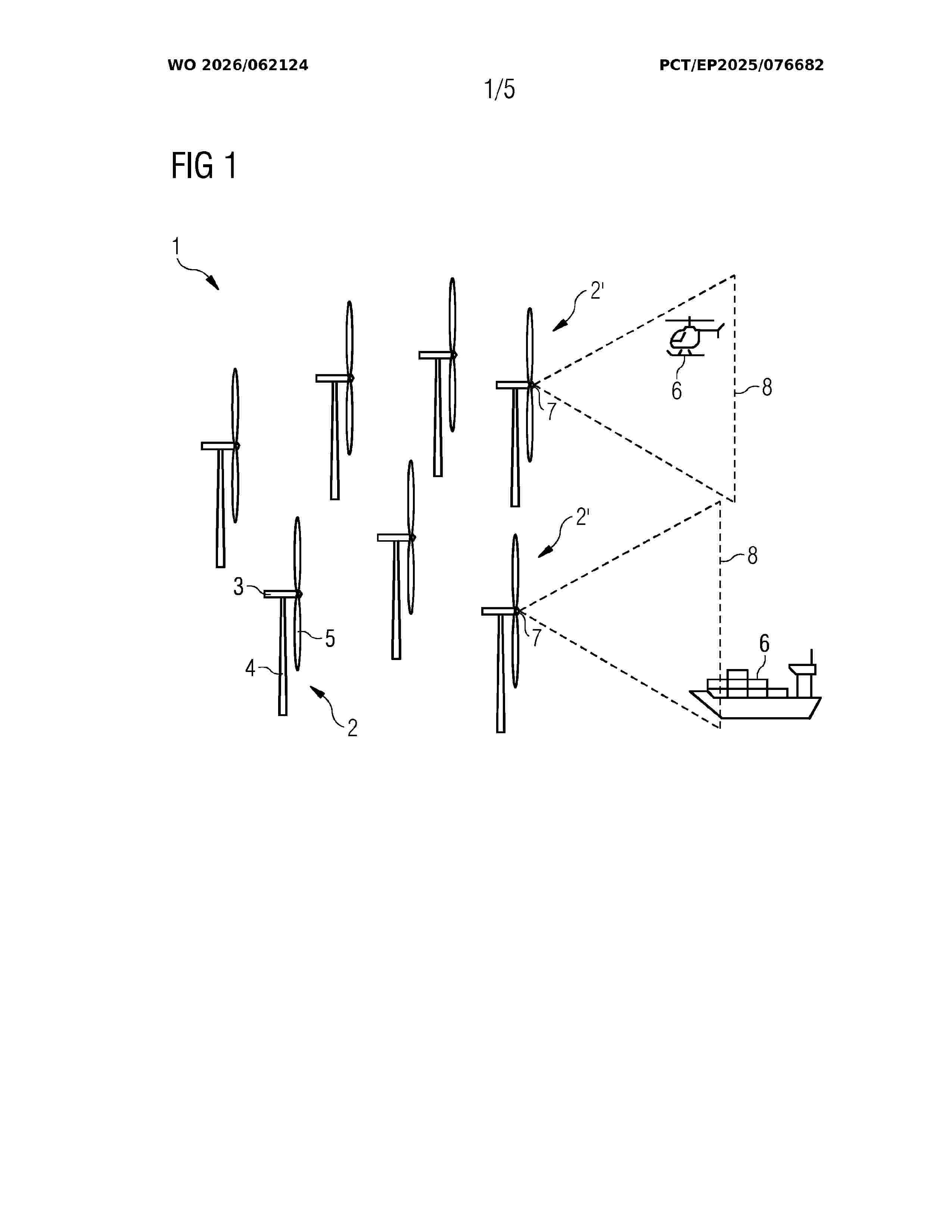
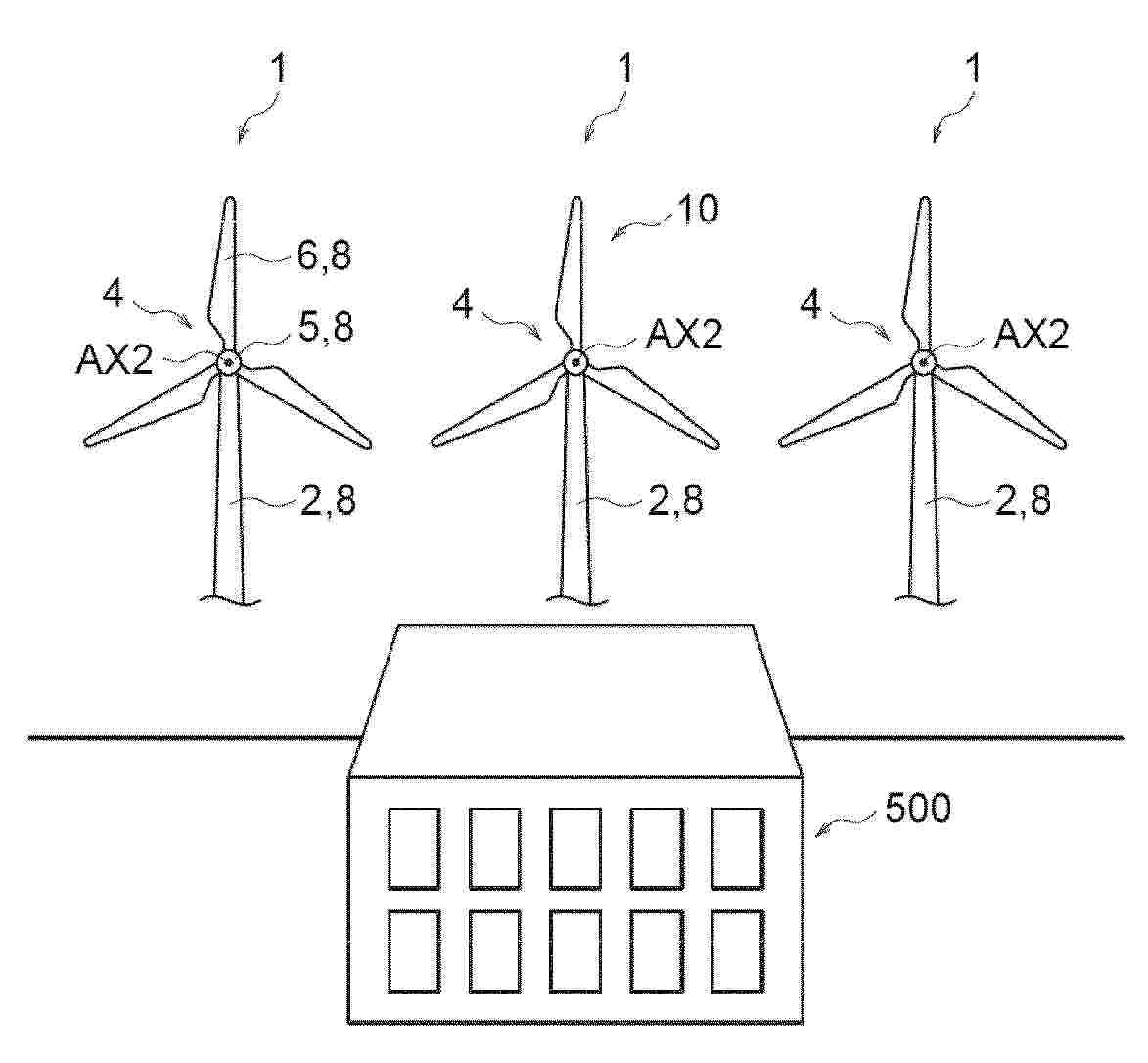
The present invention relates to a method to control a wind turbine (2) in a wind farm (1) with multiple wind turbines (2), the method including providing detection means (7) adapted to detect objects (6) entering a detection zone (8) associated with at least one of the wind turbines (2), wherein the method further includes, - a step (100) of detection of an object (6) entering the associated detection zone (8) of a wind turbine (2), the wind turbine (2) upon detection of such an object (6) being an affected wind turbine (2'), - a step (110) of operating the affected wind turbine (2') in a safety mode involving at least reducing the spinning speed of the affected wind turbine (2') rotor, The present invention further relates to the wind farm (1) controlled accordingly, and a controller performing the control. (Figure 1)
Resumen de: JP2026054423A
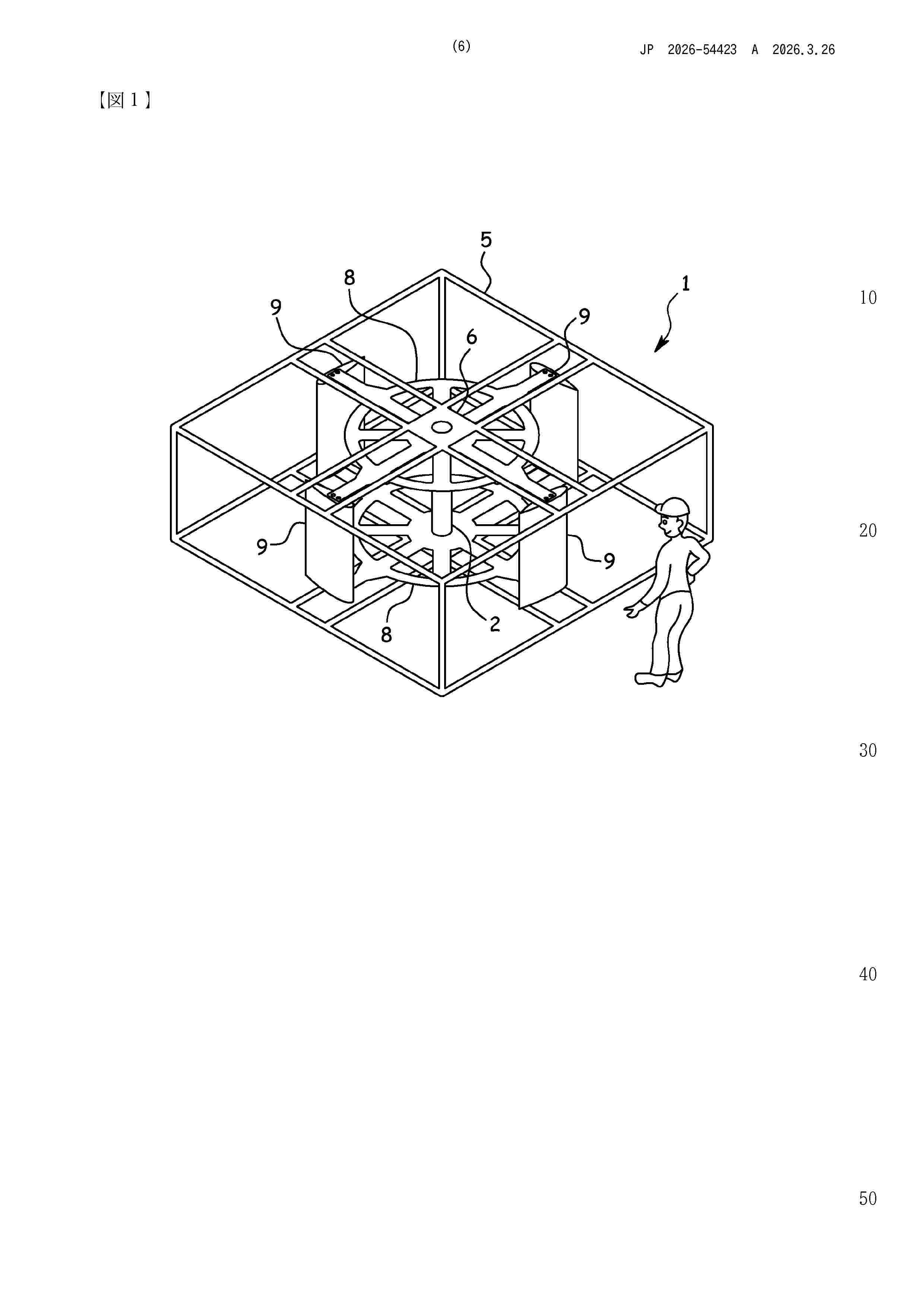
【課題】大きな予備電源が不要で且つ風車を停止させる力が強い垂直軸風車の緊急停止構造を提供する。【解決手段】垂直回転軸2が予め設定された限界回転速度に達した場合に、ウェイトWのストッパー19が解除され、ウェイトWの自重によりブレーキ部14が駆動してロータ10を所定の圧力で挟込むため、風車の回転を緊急停止することができる。ウェイトWの自重によりブレーキ部14を駆動させるため大きな予備電源が不要である。また垂直回転軸2と一体のロータ10をブレーキ部14が直接挟み込むため風車を停止させる力が強い。また復元機構が設けられているため、復元して再度使用することができる。【選択図】 図4
Resumen de: MX2025009976A
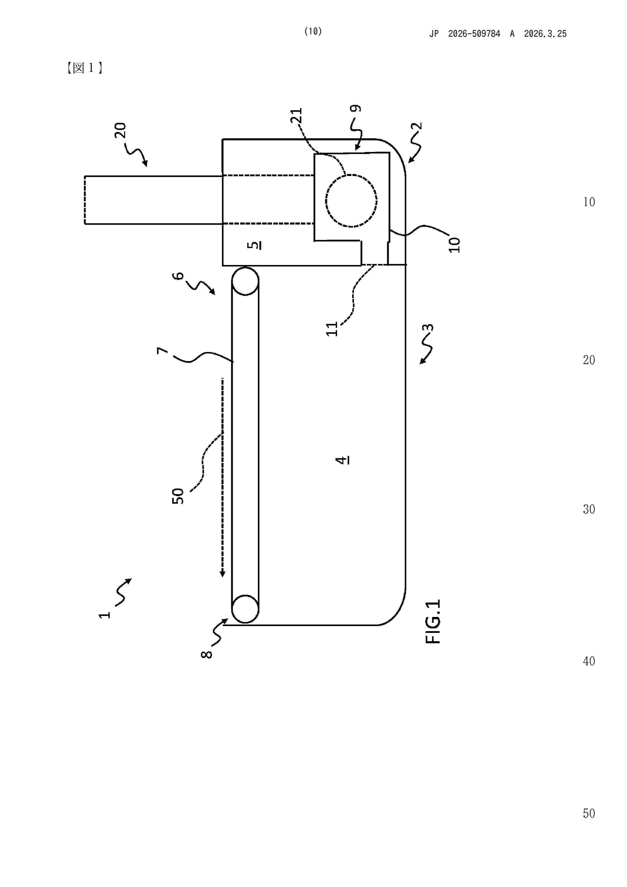
Machine (1 ) for automatic cutting of fabric comprising: - a cutting plane (7) at an upper face (8) of a box (3) and comprising a plurality of pass- through openings; - a suction system (9) for drawing air from the interior (4) of the box; - a turbine (30) located downstream of the suction system and structured to extract energy from the exhaust air flow generated by the suction system and convert it into rotational mechanical energy; - an electric generator (40) mechanically coupled to the turbine (30) and structured to convert the rotational mechanical energy of the turbine into electrical energy.
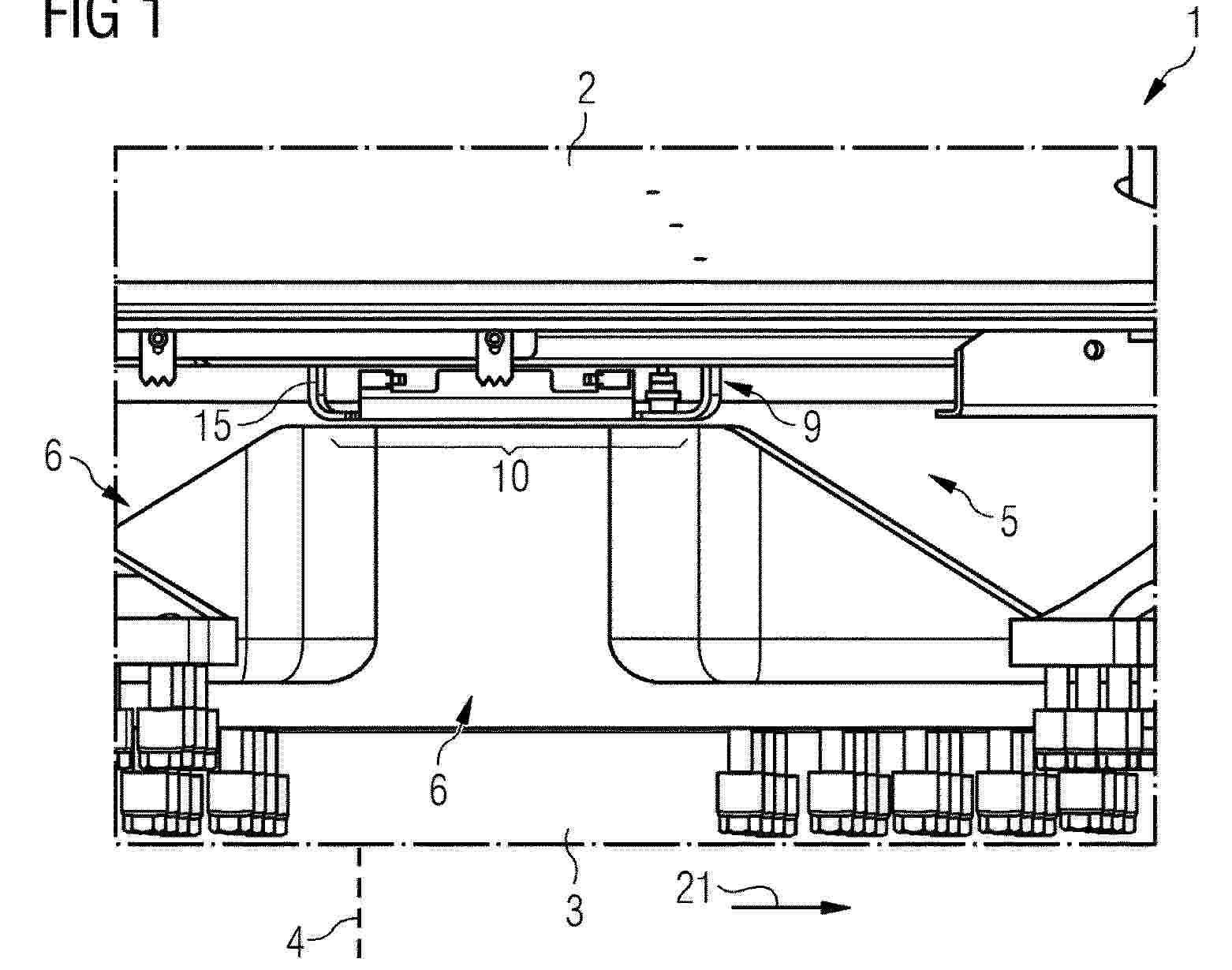
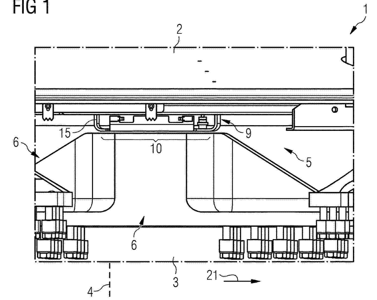
Resumen de: WO2024236111A1
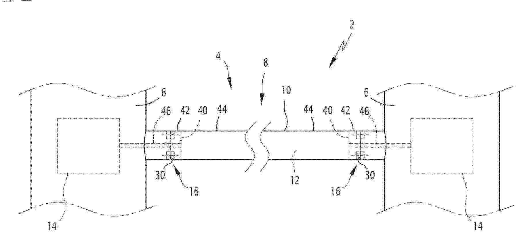
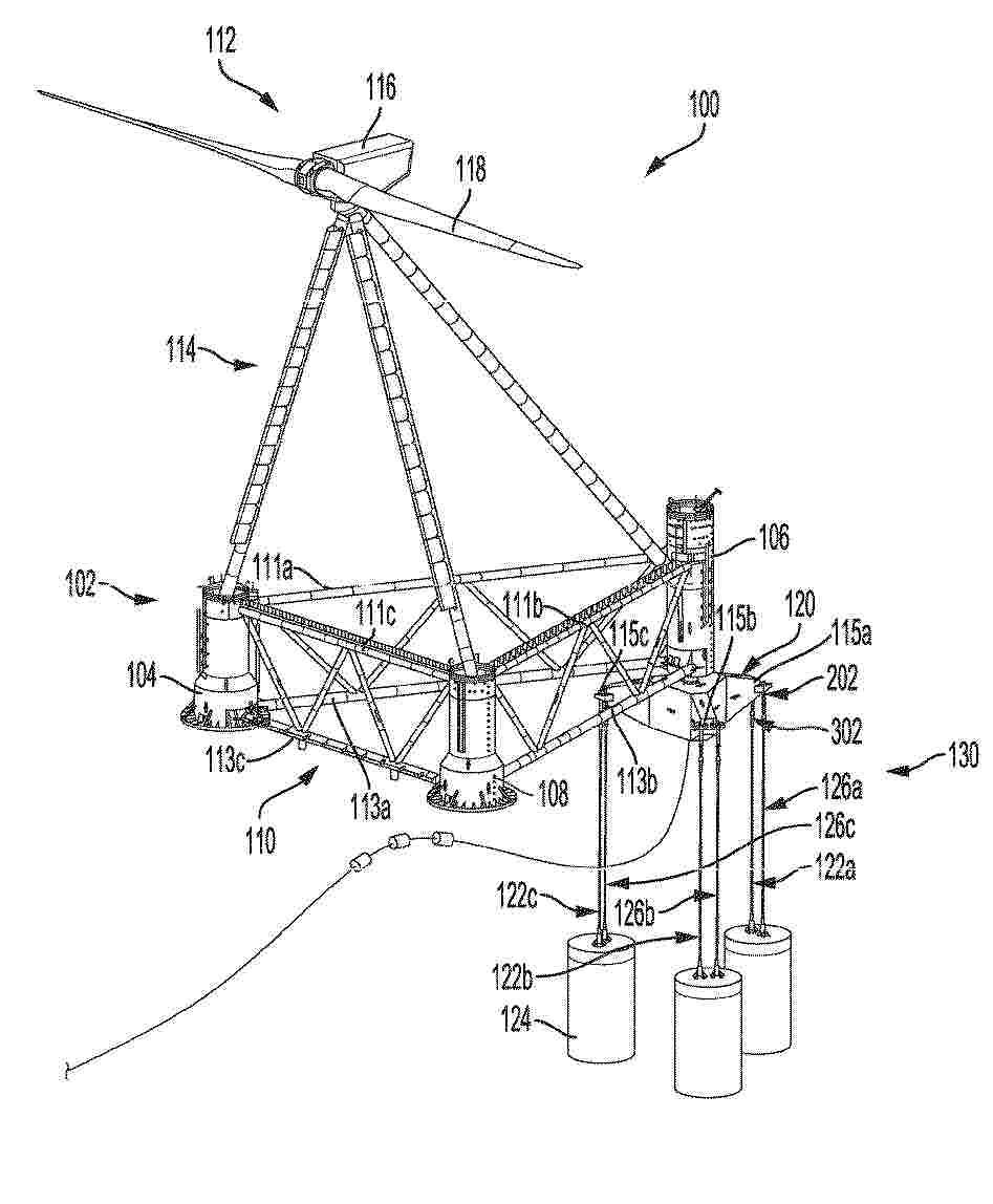
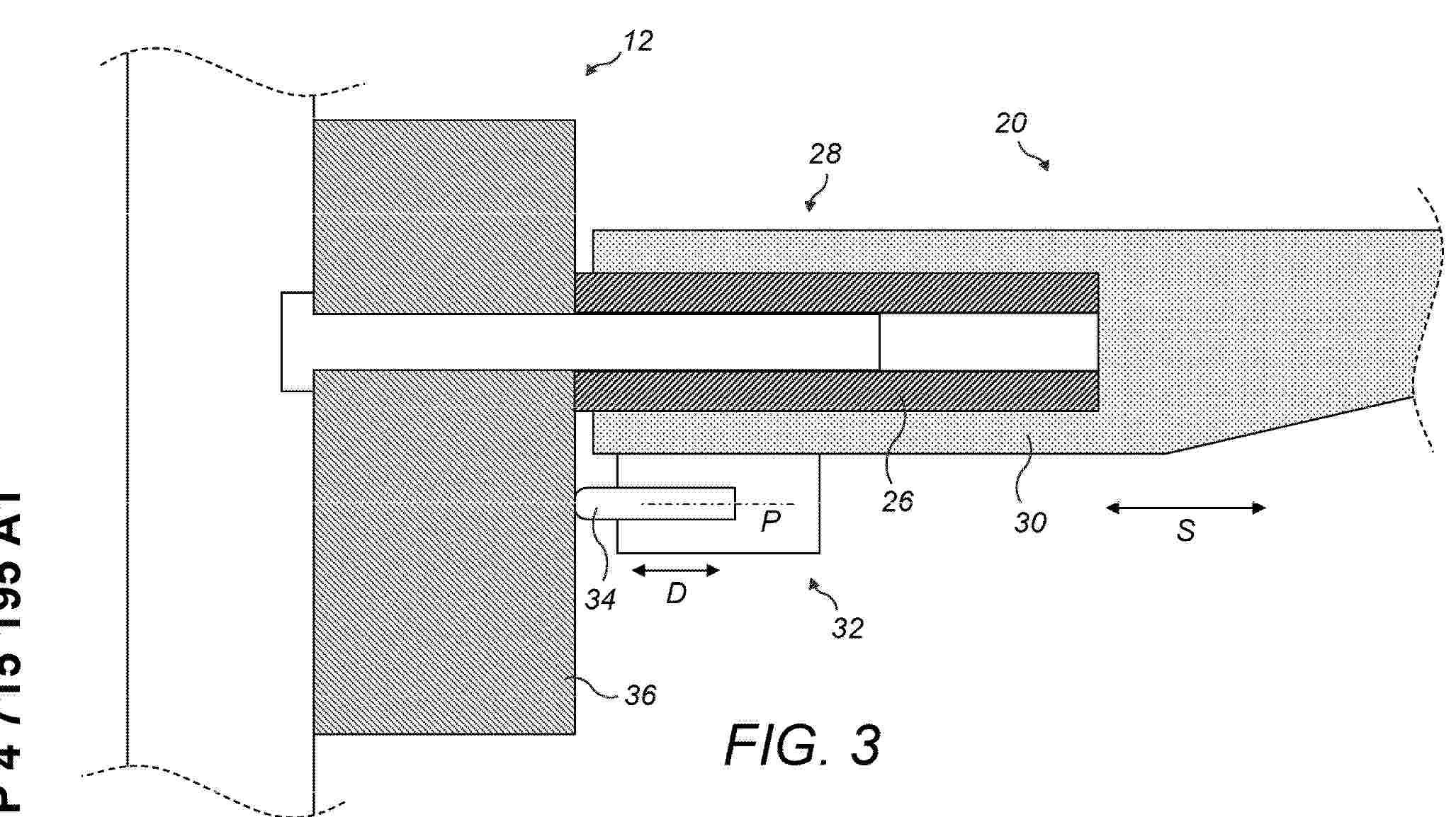
A support structure (4) of the floating offshore platform comprises a beam (8) formed of one or several tubes (10) with a tank (12) delimited inside one or several tubes (10) of the beam (8), and a least one bolted flange connection (16) connecting an end of one tube (10) of the beam (8) to another structural element (6) of the support structure (4), each bolted flange connection (16) comprising a first flange (20) and a second flange (22) bolted together with bolts (24), wherein at least one bolted flange connection (16) is sealed with a sealing assembly (32) comprising at least one sealing member (34) configured for sealing the bolted flange connection (16).
Resumen de: EP4715202A1
An aerial vehicle obtains information regarding the external condition of a wind turbine. The wind turbine includes a tower, a nacelle rotatably supported by the tower, and a wireless charging device provided in the nacelle for charging the aerial vehicle. The aerial vehicle charged by the wireless charging device can stably acquire information regarding the appearance of the wind turbine without being limited in an available flight time.
Resumen de: EP4714816A1
A tensioned leg floating platform mooring system and related methods may be used to secure the position of a floating platform. For example, the floating platform mooring system may include at least three fixed-length mooring lines coupled at different locations between a floating platform and one of one or more mooring piles. Additionally, the tensioned leg floating platform mooring system can include an adjustable-length mooring line coupled between the floating platform and one of the one or more mooring piles. The floating platform mooring system may further include a mooring line tension device coupled to the adjustable-length mooring line. The mooring line tension device may adjust a tension of the adjustable-length mooring line by adjusting a length of the adjustable-length mooring line in situ.
Resumen de: EP4715200A1
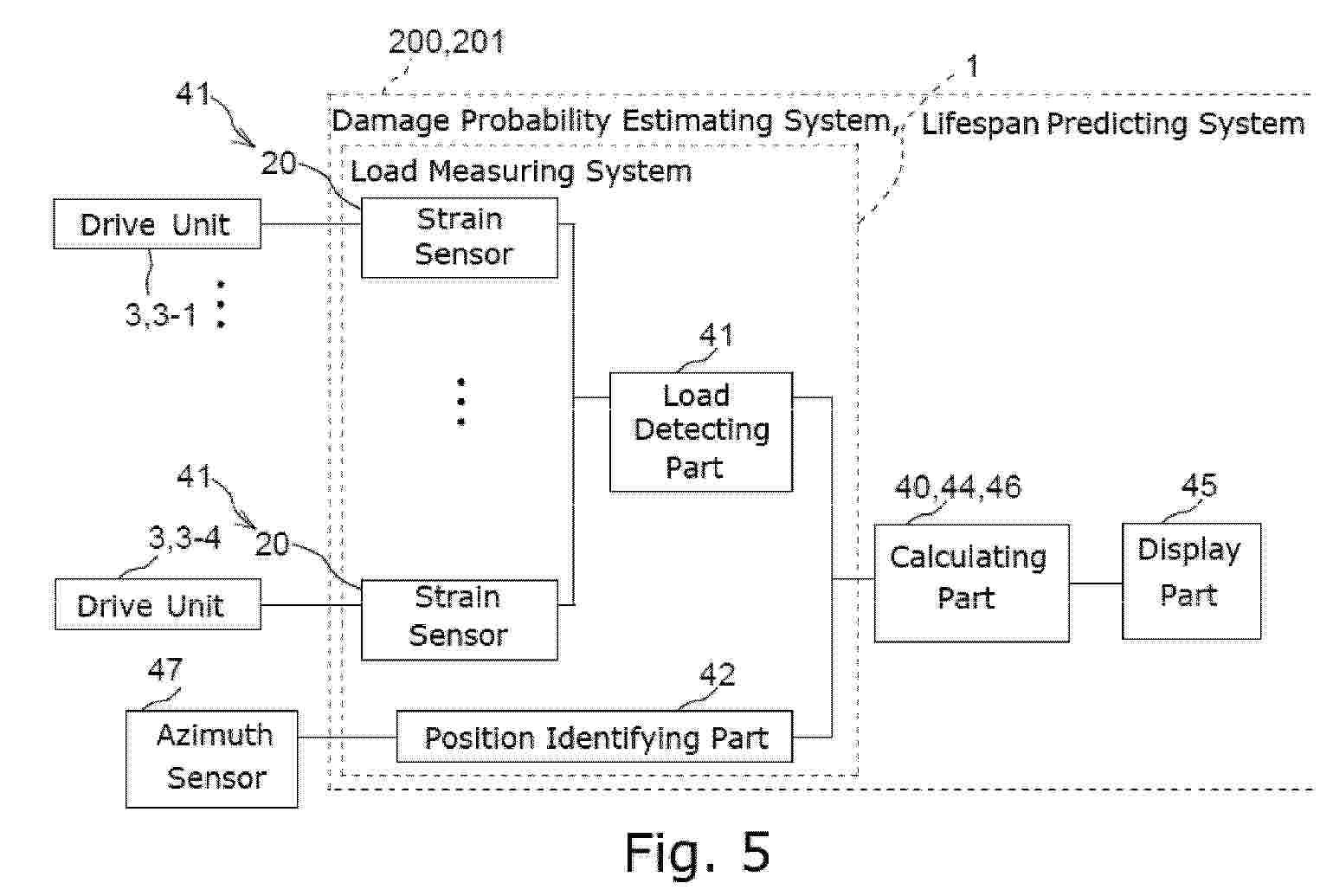
It is determined which of the teeth of a ring gear are subject to a load and to what extent the load is exerted. A load measuring system includes: a load detecting part for use in a moving part of a wind turbine, the moving part including a ring gear with a plurality of teeth and at least one drive unit with a pinion meshing with the ring gear, the load detecting part being configured to detect an applied load that is exerted on a tooth of the ring gear due to application of an external force or a driving force of the drive unit via the pinion with the ring gear meshing with the pinion; and a position identifying part for identifying, from among the teeth of the ring gear, a target tooth subject to the applied load.
Resumen de: EP4715143A1
An assembly stand (1) and associated method for assembling a concrete ring (11) from a plurality of concrete segments (10), the assembly stand (1) comprising a plurality of beams (2) configured to support the concrete segments during their assembly into the concrete ring, in particular the beams mounted with a star configuration from the central axis, a movement mechanism (3) mounted on one or of more of the plurality of beams (2), in particular mounted on all beams (2), wherein each movement mechanism (3) is configured to contact or engage with an underside of the concrete segments (10) and to allow a controlled movement of the concrete segments (10) relative to the beam (2) when an assembly force (F) is applied.
Resumen de: EP4715205A1
It is described a method of detecting when a rotor (3) of a wind turbine (40) is in a rotor locking position for locking the rotor, the wind turbine comprising a stator (2) relative to which the rotor (3) is rotatable, the method comprising: rotating the rotor (3); receiving sensor output data (12) from a sensor system (10) sensitive to distance between stator and rotor components; analysing the sensor output data (12); indicating when the rotor locking position is reached based on the analysed sensor output data.
Resumen de: EP4715204A1
It is described a locking system, including an electric motor system and method of locking a rotor and in particular detecting when a rotor (3) of a wind turbine (40) is in a rotor locking position for locking the rotor, the wind turbine comprising a stator (2) relative to which the rotor (3) is rotatable, the method comprising: rotating the rotor (3); receiving sensor output data (12) from a sensor system (10) sensitive to distance between stator and rotor components; analysing the sensor output data (12); indicating when the rotor locking position is reached based on the analysed sensor output data.
Resumen de: EP4715197A1
A method for damping drivetrain vibrations of a wind turbine. The drivetrain has, at least, a rotor and a generator. The method includes receiving a first rotational speed signal at a first location along the drivetrain, the first rotational speed signal being a proxy for rotor speed of the rotor. The method also includes receiving a second rotational speed signal at a second location along the drivetrain, the second location being downwind from the first location, the second rotational speed signal being a proxy for generator speed of the generator. Further, the method includes determining a speed error based on a comparison of the first and second rotational speed signals. Moreover, the method includes determining a torque deviation signal for the wind turbine configured to dampen the drivetrain vibrations when the speed error exceeds a first speed threshold. In addition, the method includes applying the torque deviation signal to the generator to dampen the drivetrain vibrations.
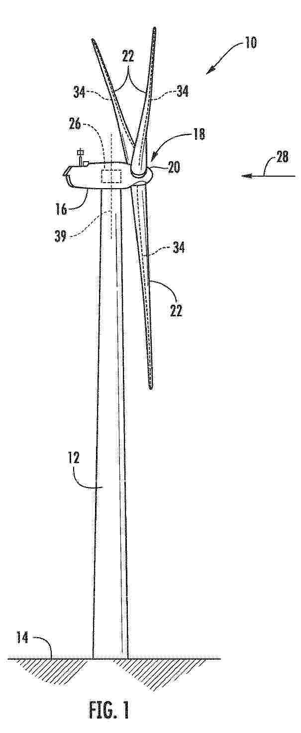
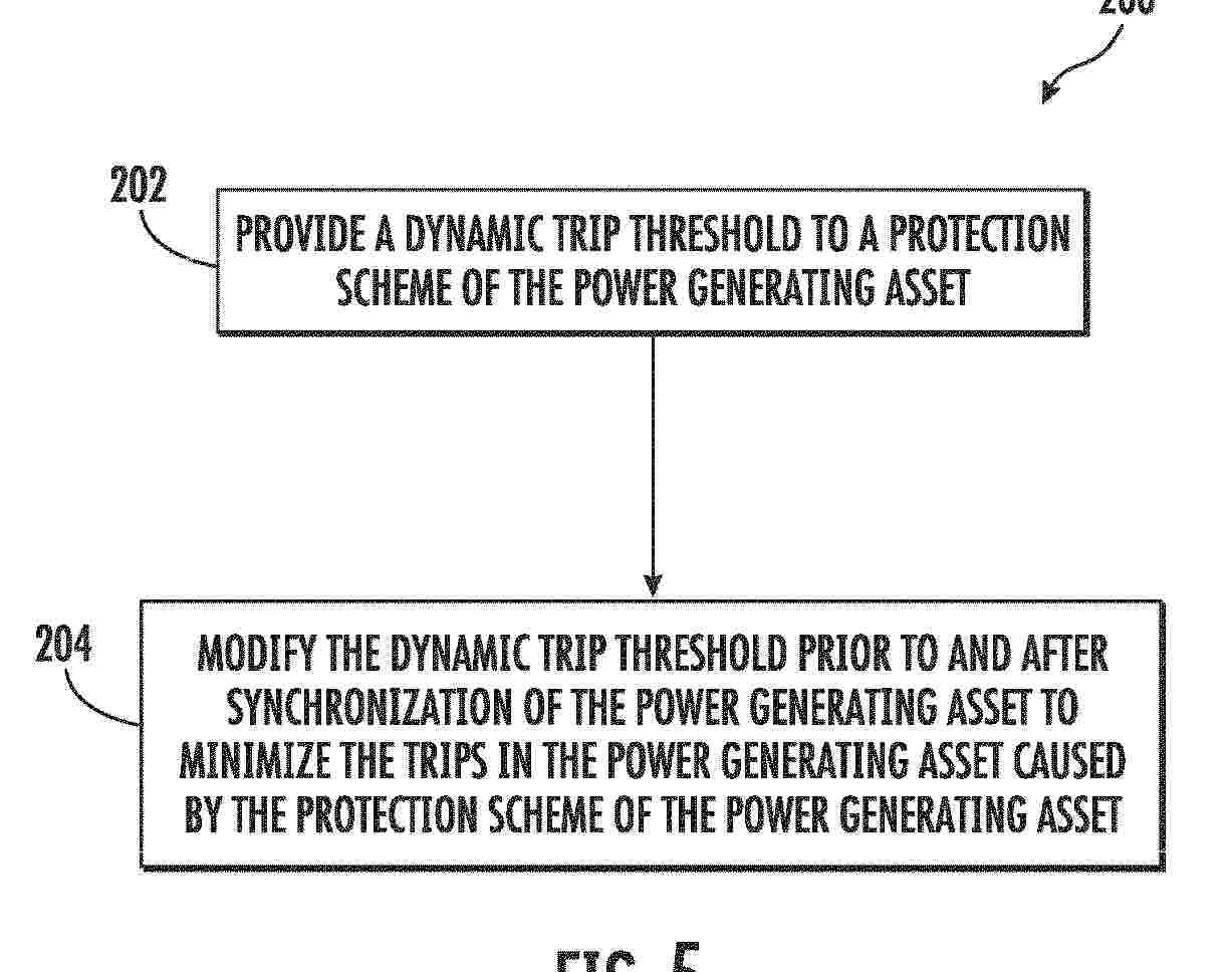
Resumen de: EP4716048A1
A method for minimizing trips in a power generating asset prior to synchronization includes providing a dynamic trip threshold to a protection scheme of the power generating asset and modifying the dynamic trip threshold prior to and after synchronization of the power generating asset to minimize the trips in the power generating asset caused by the protection scheme of the power generating asset.
Resumen de: EP4715195A1
In a first aspect of the present invention there is provided a wind turbine comprising a hub assembly, a blade part attached to the hub assembly, and a displacement sensor array comprising a plurality of displacement sensors. Each displacement sensor is attached to one of the blade part or the hub assembly. Each displacement sensor comprises a physical contact probe which is slidable along a probe axis in a probe direction. The physical contact probe of each displacement sensor physically contacts the other of the blade part or the hub assembly such that the displacement sensor is arranged to detect relative movement between the blade part and the hub assembly in the probe direction.
Resumen de: US12435757B1
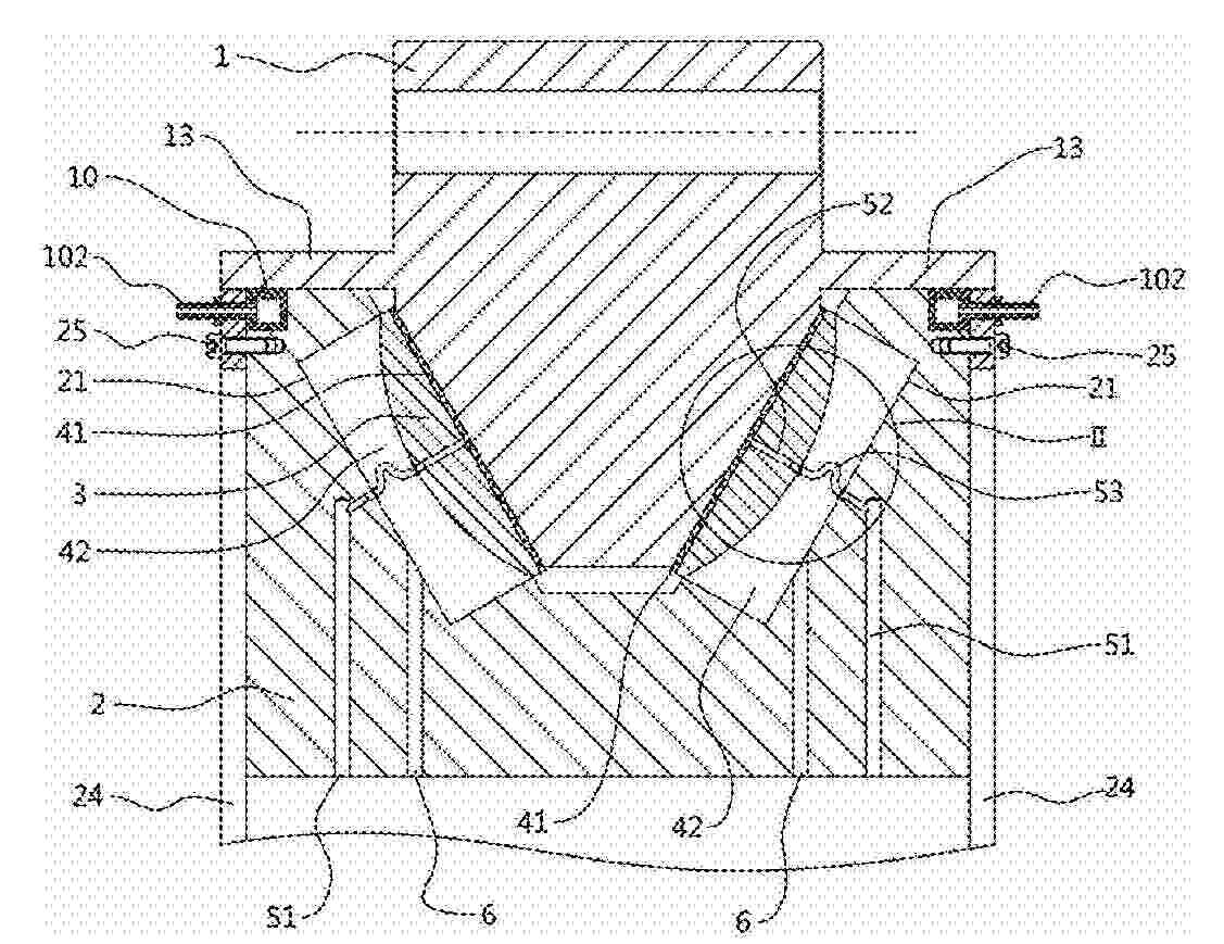
A wind power main-shaft sliding bearing with bidirectional stresses and a wind power generation system are disclosed. The wind power main-shaft sliding bearing includes an outer ring, an inner ring and a tile block. The outer ring has an isosceles trapezoidal cross-section where the inner ring slides. The inner ring has a trapezoidal groove matching the outer ring shape. Symmetrical chutes are in two inner sloping faces of the trapezoidal groove. The tile block is in a cavity between the chute and the outer ring. The face of the tile block near the inner ring is spherical. The tile block separates first and second oil cavities, respectively near the outer and inner rings. Even when the sliding bearing is stressed with a load that deforms the inner ring, the tile block automatically adjusts the tilting angle, thereby avoiding tilting the outer ring due to operating pressure loss.
Resumen de: EP4714818A2
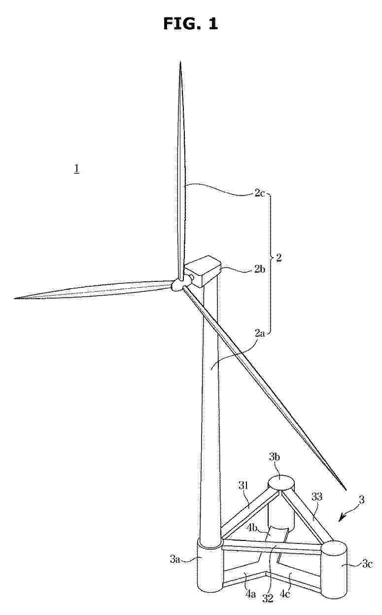
A floating wind power generation device may include a power generation unit configured to perform a wind power generation action, and a floating body provided to support the power generation unit, wherein the floating body includes a main column configured to support the power generation unit, a plurality of auxiliary columns provided around the main column, a plurality of connecting members configured to connect the main column and each of the plurality of auxiliary columns, and a plurality of pontoons provided below the plurality of connecting members with respect to the direction of gravity to support a self-weight of the main column and the plurality of auxiliary columns.
Resumen de: EP4714817A2
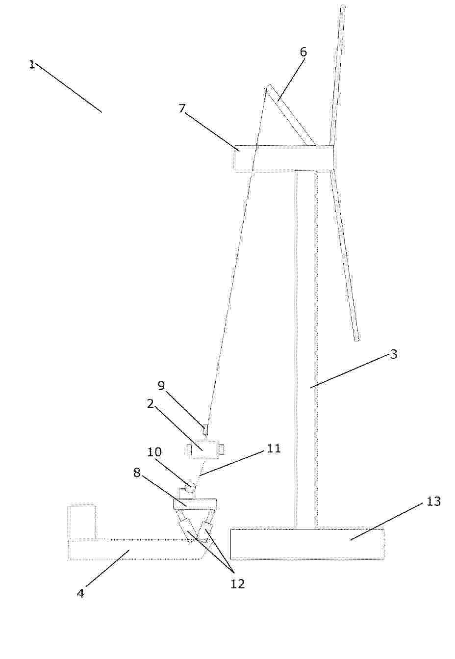
A method and a system (1) for controlling transfer of a suspended load (2) between an offshore wind turbine (3) and a floating vessel (4) are disclosed. Movements, relative to the floating vessel (4), of a load (2) suspended in a hoisting mechanism (6, 15) and/or of a hooking part (9) of the hoisting mechanism (6, 15), are detected. A position and/or inclination of a landing platform (8) arranged on the floating vessel (4) is adjusted, based on the detected movements, in order to compensate for relative movements between the floating vessel (4) and the suspended load (2) and/or the hooking part (9), thereby synchronizing movements of the landing platform (4) to movements of the suspended load (2) and/or the hooking part (9), while moving the suspended load (2) and/or the hooking part (9) towards the adjustable landing platform (8). The step of detecting movements of a load (2) suspended in the hoisting mechanism (6, 15) and/or of a hooking part (9) of the hoisting mechanism (6, 15) comprises detecting the movements by means of one or more sensors arranged on the suspended load (2) and/or the hooking part (9). A step of communicating sensor readings from the one or more sensors to a control unit for controlling the adjustable landing platform (8) is further comprised
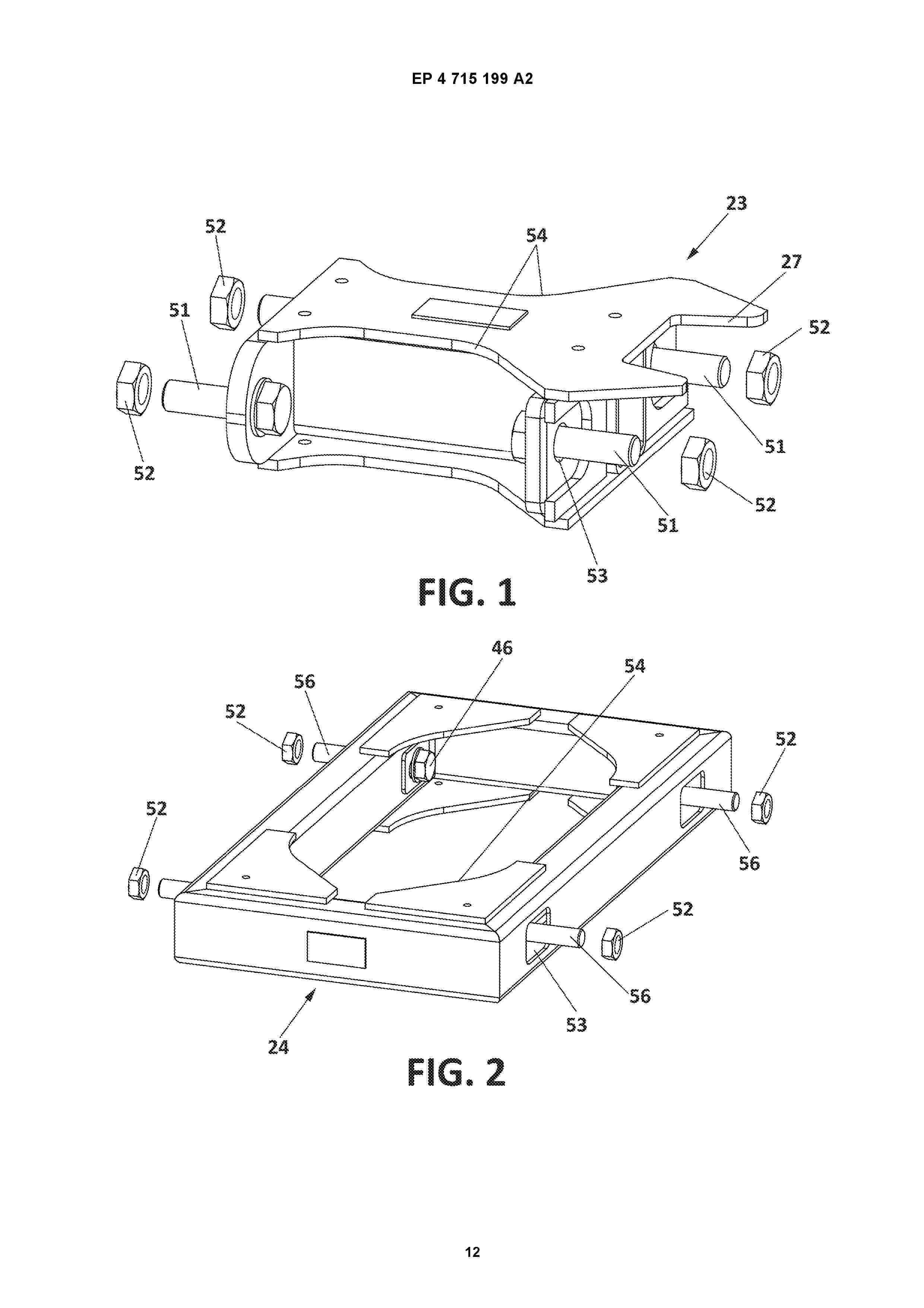
Resumen de: EP4715199A2
The present invention relates to a wind turbine rotor blade spacer, a transportation and storage system for wind turbine rotor blades and a related method that prevent the vertical flexion of each one of the blades assemblies, minimizing the stresses and avoiding the contact between vertically and/or horizontally adjacent blades, and in consequence, blade damage. Also, the overall occupied surface by the system once assembled is minimised.
Resumen de: EP4715142A1
Ein Adapterstück (1) zur Verbindung eines unteren, ringförmigen Betonturmabschnitts (2) mit einem oberen, ringförmigen Stahlturmabschnitt (3), insbesondere eines Windkraftturms (4) ist als Beton-Stahl-Verbundteil mit einem ringförmigen Stahlelement (5) und einem ringförmigen Betonelement (6) ausgebildet. Das ringförmige Stahlelement (5) umfasst einen oberen, insbesondere L-förmigen, Befestigungsflansch (7) zum Verbinden mit dem Stahlturmabschnitt (3). Das Adapterstück (1) umfasst eine Anlagefläche (8), mit der das Adapterstück (1) auf dem Betonturmabschnitt (2) anordenbar ist. Dabei weist das Betonelement (6) die Anlagefläche (8) auf und das ringförmige Stahlelement (5) weist einen unteren, insbesondere T-förmigen, Flansch (9) auf, welcher eine Oberseite (10) des Betonelements (6) bedeckt. Ein Turm mit einem unteren, ringförmigen Betonturmabschnitt (2) und einem oberen, ringförmigen Stahlturmabschnitt (3) weist ein solches Adapterstück (1) auf.
Nº publicación: EP4715203A1 25/03/2026
Solicitante:
FABRICAIR CANADA INC [CA]
FabricAir Canada Inc
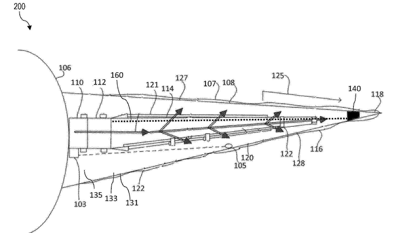
Resumen de: EP4715203A1
Provided herein are duct support systems and methods for installing and supporting a flexible duct in an interior of a wind turbine blade. The system comprises a duct support including an eyelet and at least one bonding surface, wherein the bonding surface is glued to an interior surface of the wind turbine blade near a tip of the wind turbine blade, and a cable, wherein the cable is connected to a tip-most end of the flexible duct, the cable passes through the eyelet of the duct support, and the cable passes through the flexible duct, whereby the flexible duct can be retracted from or deployed to the tip of the wind turbine blade by pulling the cable in a respective direction.
 BOPI
BOPI
 Sede Electrónica